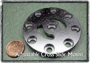
An adjustable (rotatable) cross slide mount for the Cowells lathe
The vertical slide, machine vise, dividing head, etc attach to the cross slide of the Cowells lathe using two of the three T-slots, which, of course, offers the choice of two positions. They must be mounted in one of four, 90 degree positions. However, there are instances where the ability to position these at other angles would be useful. For example, milling a 45 degree face onto work held in the machine vise or dividing head and mounted on the vertical slide. A means of rotating a vertical slide was found in an article in the November, 2000 issue of Model Engineers' Workshop magazine. The plans were for a rotatable mount to be used with a similar type of vertical slide on a Myford lathe. I adapted these plans for the Cowells lathe, which has primarily only been a change in the dimensions used.
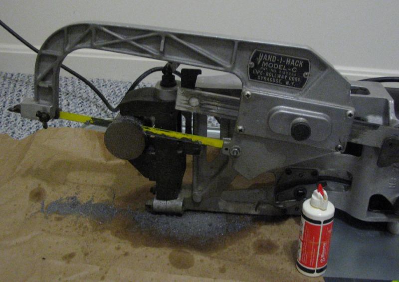
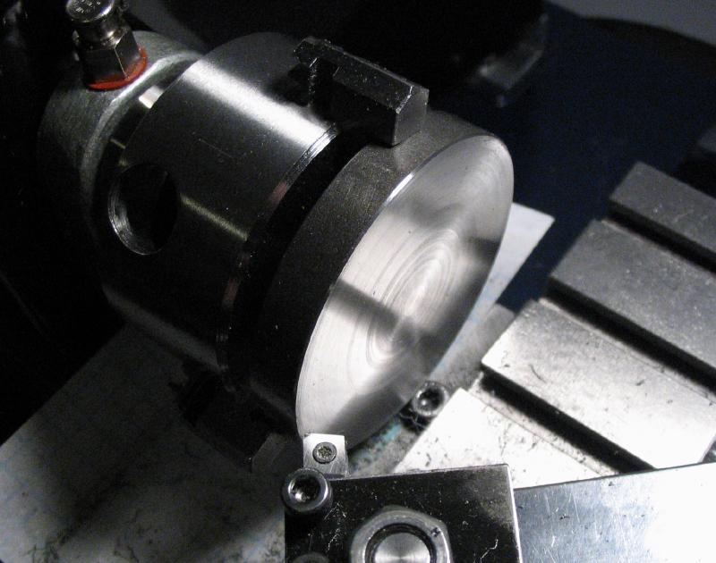
The mount was started from a 10mm thick disc of 2-3/8" diameter mild steel rod (type 1018). The Hand-I-Hack definitely did the hard work here.
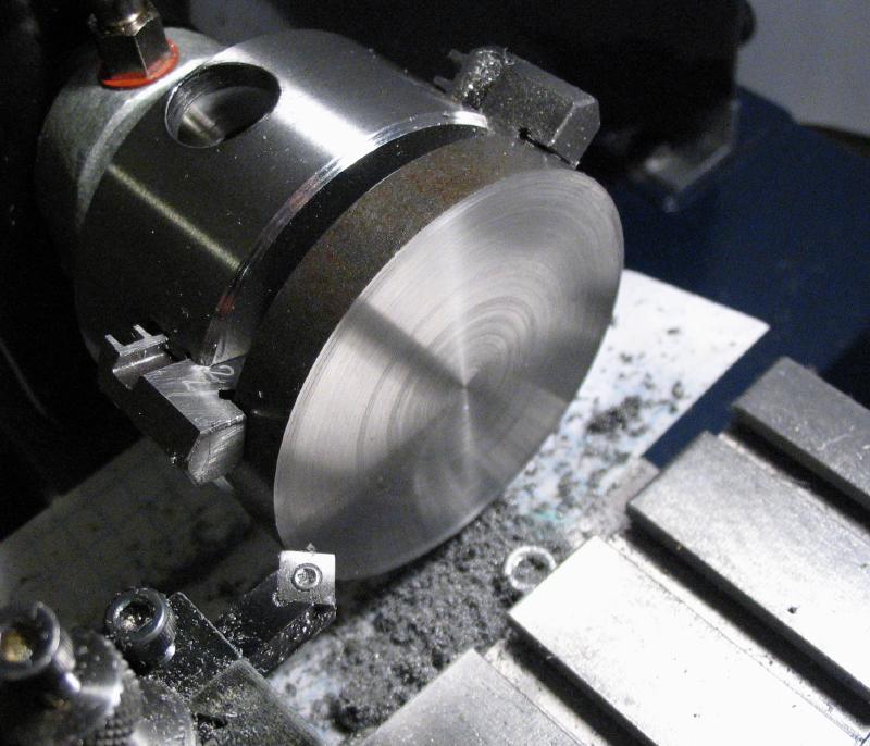
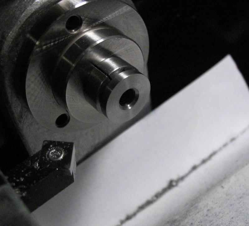
The disc was mounted in the 3-jaw chuck of the lathe and both sides faced and chamfered. One side was center drilled for center reference in the next steps.
|
|
|
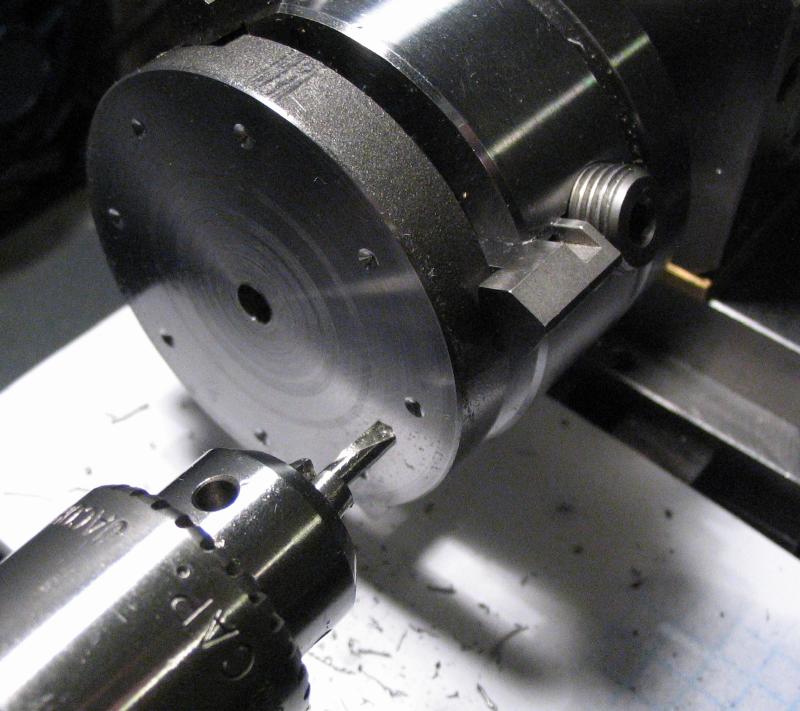
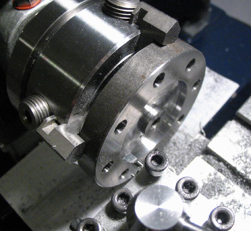
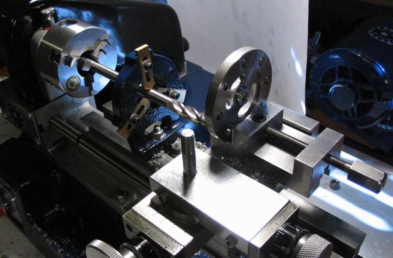
The disc was then transferred to an independent 4-jaw chuck. First, the dividing head was mounted onto the cross slide using a riser to bring it onto lathe center height, and the dividing head spindle centered with the headstock spindle using the cross slide. The 4-jaw chuck was then attached and the jaws adjusted so as to bring the disc onto center, using a 60 degree male center in the headstock for reference.

|
|
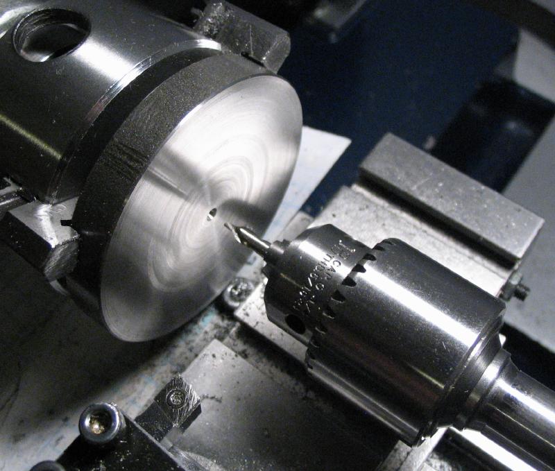
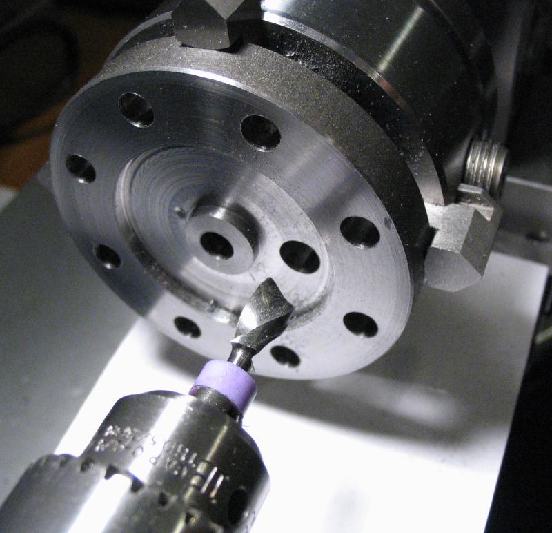
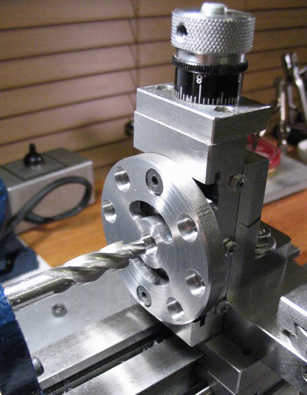
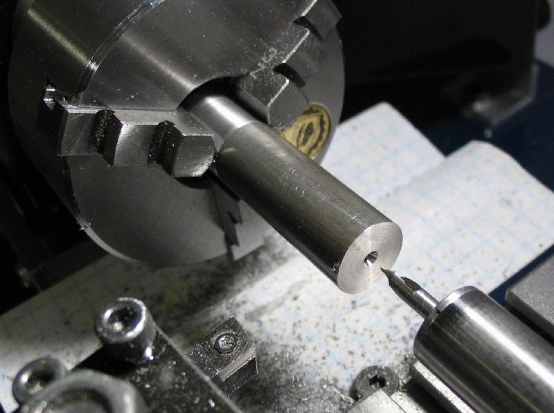
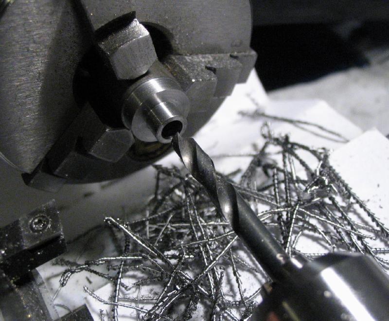
The disc was drilled through 5.5mm to pass an M5 screw with plenty of clearance.
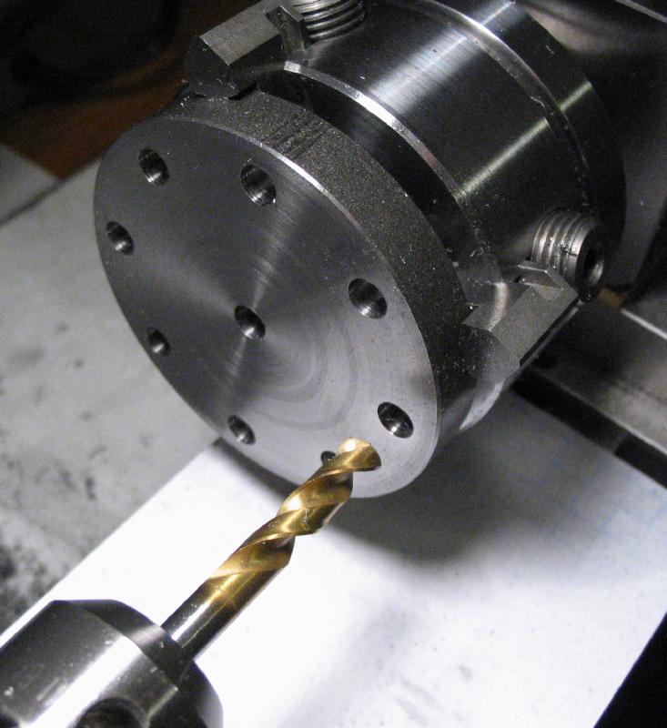
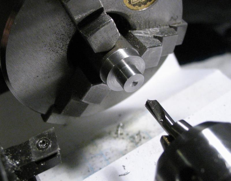
One of the jaws of the chuck is put onto lathe center height and the dividing head used to then rotate the chuck 22.5 degrees. This will allow the drill to pass through the disc and not foul the chuck jaw. Eight 5.5mm holes were drilled on a 48mm 'bolt circle,' 45 degrees apart. I would have counterbored these nine positions for socket head screws after drilling, however, I planned to use a commercially made M5 counterbore and discovered that the shank of it was simply too large to be mounted and used with this setup, so this will have to wait for now.
|
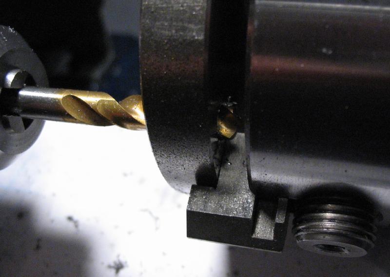
The drill bit can be seen as it passes through.
|
|
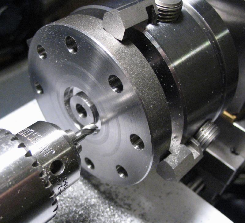
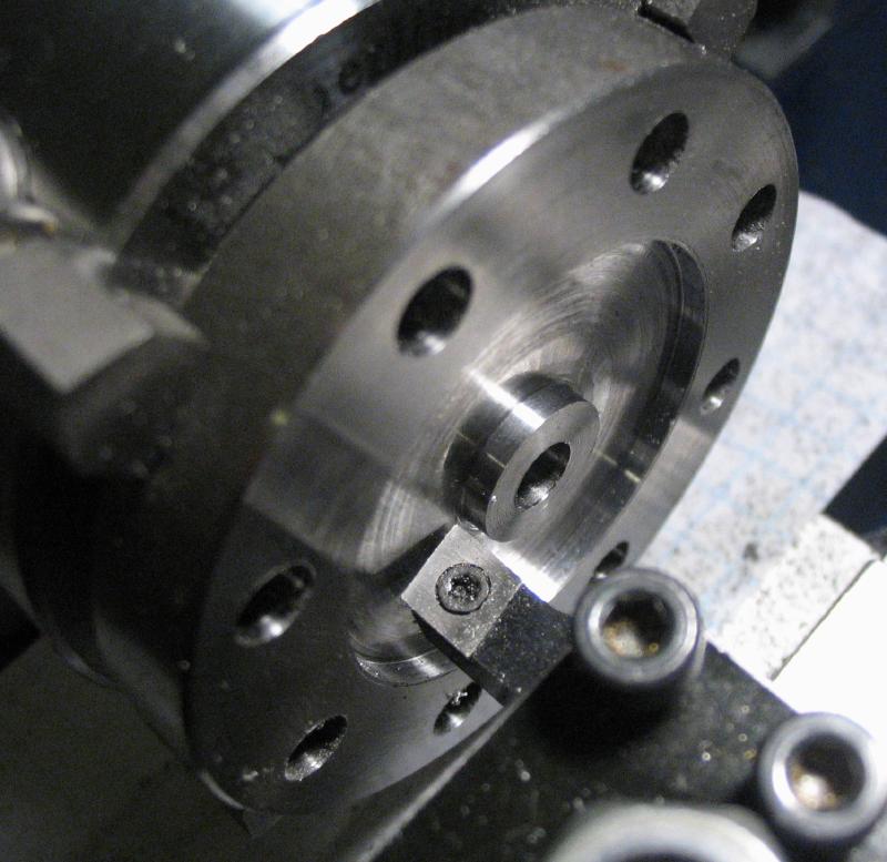
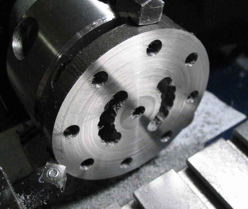
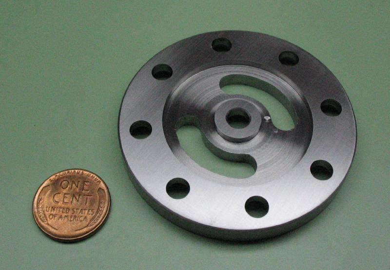
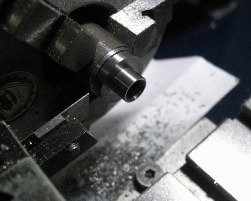
A circular channel was milled into the face of the disc to a depth of 2.2mm using an 1/8" endmill, leaving an inner boss with a diameter of about 12mm. This is the start for the recess that will be used for the t-bolts of the vertical slide. The dividing head was used to feed the disc while milling, which is a misuse of the dividing head and must be done with care. The chuck (with work still attached) was transferred to the headstock to finish the recess by boring. The milled channel provides a very convenient starting point for the boring bar to fit into. The recess was bored to a diameter of 36mm. The inner boss was turned true to remove the rather ragged surface left from the endmill.
|
|
|
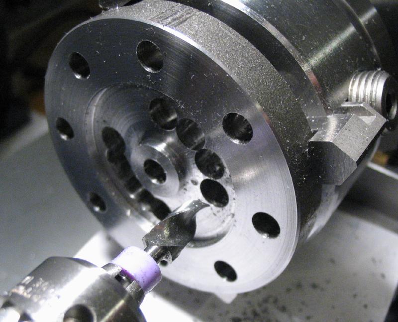
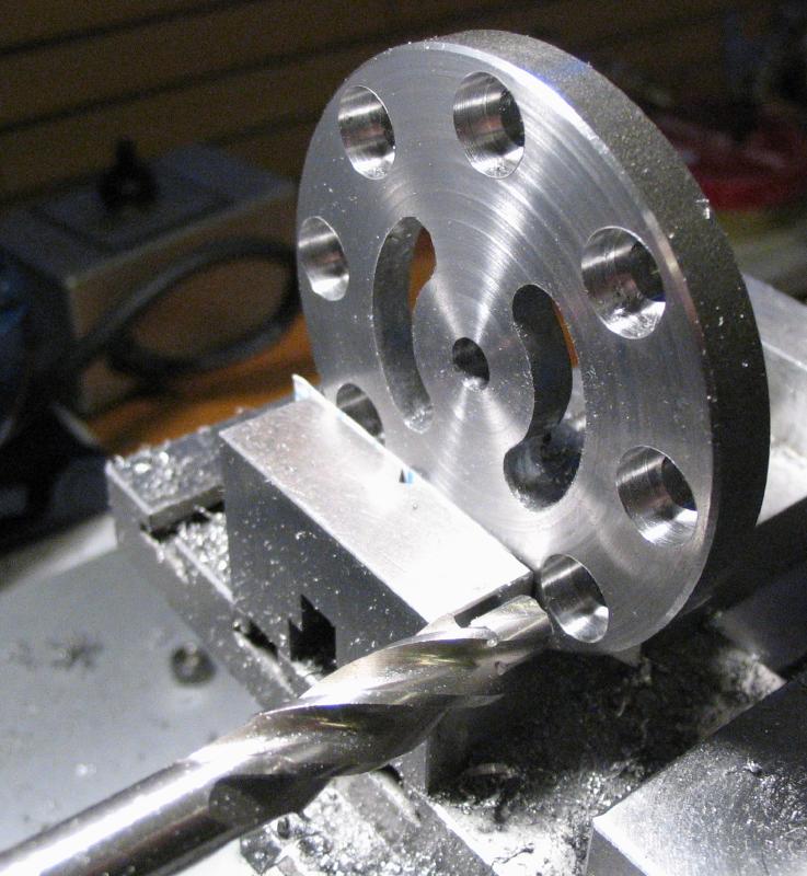
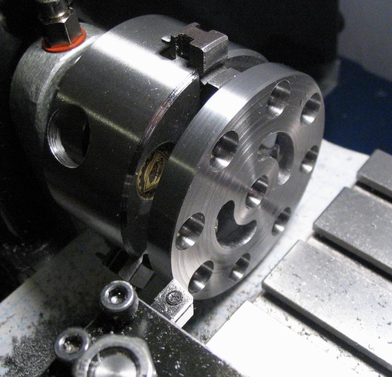
The work was returned to the dividing head and the slots for the T-bolts were formed by chain drilling 1/4" on a 12mm radius in 30 degree increments for a total of 90 degrees, and then repeated diametrically. As can be seen in the photo, additional drilling was done to remove more material, which saves time while filing but the interrupted-cut drilling is slow as well.
|
|
I made a change to the design at this point. I intended to use regular socket head screws, but discovered that a low-profile type of socket head screw is available that is about 1.5mm shorter, which means the mount can be made a bit thinner. It was mounted in the 3-jaw chuck and the top side of the mount was faced to the new (but not final) thickness (7mm).
I also realized at this point that the Cowells vertical slide will not overhang the mount sufficiently to allow the slide to pass. This limits the usefulness of this design quite a bit (quite the opposite is true for the version described in Model Engineers' Workshop, but the relative dimensions on the Myford are different). This problem combines with the fact that the mount itself raises the height of the vertical slide, so I wanted to reduce the height as much as possible.
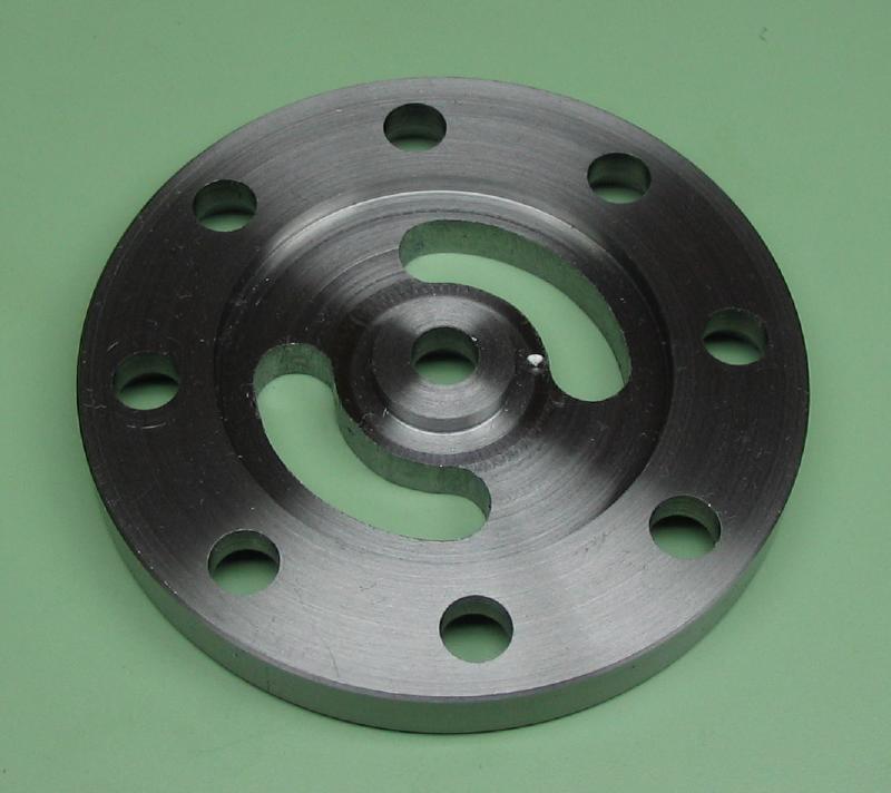
The slots for the T-bolts were finished by filing, a large half-round file works well for this.
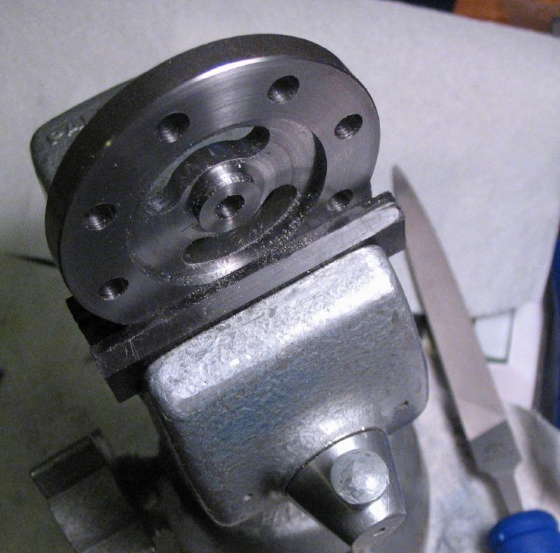
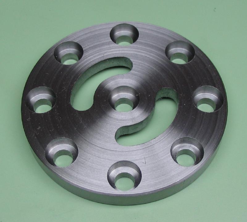
The bolt positions were counterbored using a M5 counterbore with the work setup in the machine vise. The size of the counterbore makes it awkward to use on the Cowells since it is too large to pass into the headstock. It could have been shortened by sawing off a portion of the shank, perhaps, but it was instead held in the 3-jaw chuck and supported with the steady rest. The pilot of the counterbore was used to position the work on center and the depth of the bore was 3.75mm. The socket head screws are 3.5mm deep and 0.025mm was added so that the screw heads are below the surface.
|
|
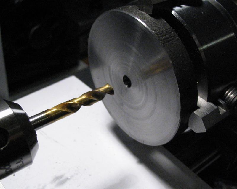
The plate could then be attached to the vertical slide using socket head screws and two of the completed screw positions to counterbore the center position, which is positioned over one the t-slots of the slide to allow the counterbore pilot to pass.
Finally, the plate was mounted in the 3-jaw chuck, gripping internally, to turn the outer diameter, but this is only cosmetic.
|
|
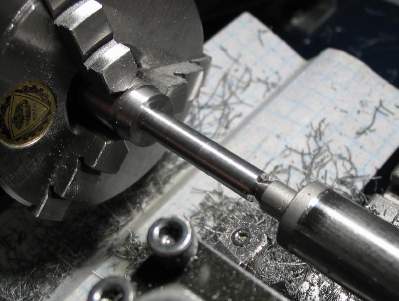
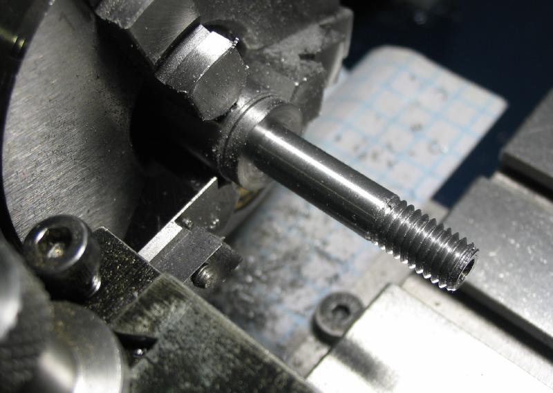
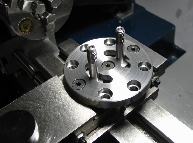
A pair of T-bolts needed to be made to suit the height of the mount and vertical slide. They were made from 1/2" mild steel rod (12L14). A short length was turned down and faced and the rod then reversed in the chuck. The rod was again faced and then center drilled for tailstock support. The rod was turned to 12mm in diameter, and then down to 6.1mm for 28mm. About 10mm was turned down to 6mm for threading M6. The T-bolt was then parted off and reversed in the chuck to face the parted end and reduce to a thickness of 2mm.

|
|
|

|
|
|
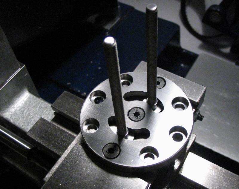
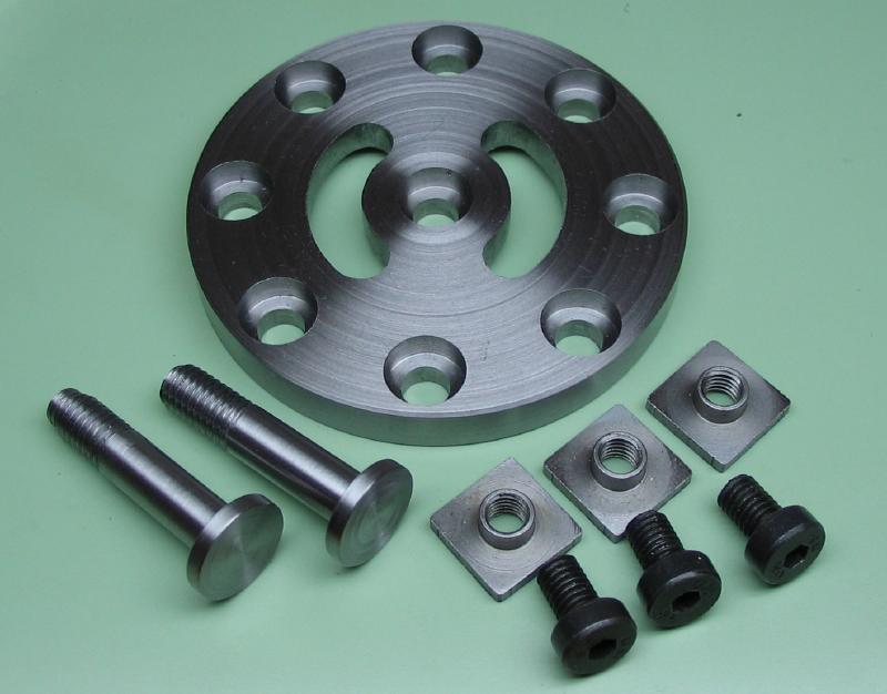
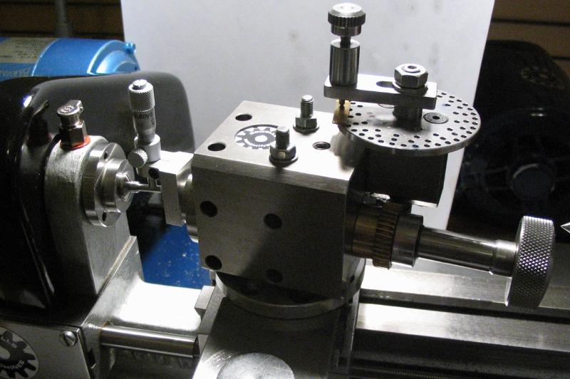
The completed hardware and three Cowells T-nuts and three low-profile socket head screws. The plate was attached to cross slide, and as can be seen in the photo, it can attached in a variety of positions, using two or three T-slots and rotated in 45 degree increments. The semi-circular T-slots provide a means to form the desired angle. The vertical slide was attached using its usual nuts and washers. It can be rotated to the desired angle and fixed by tightening the nuts. It is in its lowest position, and does not provide much travel across lathe center in the z-axis.
|
|
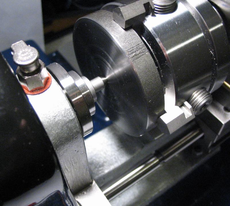
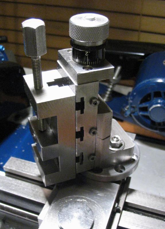
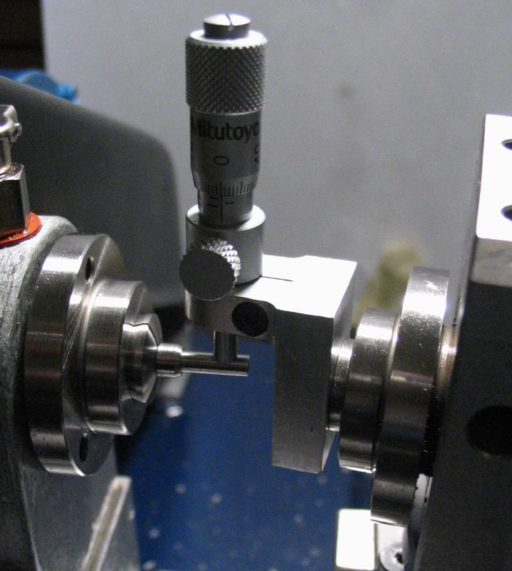
I initially started this project with the vertical slide in mind, but I discovered there are other possible uses (the vise or dividing head). I placed the dividing head onto the surface of the adjustable mount. The center micrometer was mounted in the dividing head with the reference pin held in a collet in the tailstock to determine the amount of material to remove from the face of the mount. The mount will then need to be faced to this new thickness and the depth of socket head counterbores increased to account for the change as well...

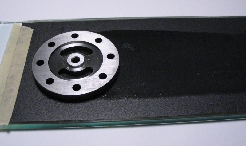
The top face was reduced to within about 0.05mm of the measured requirement and then rechecked. The depths of the counterbores were increased as well. The final thickness was found by lapping the plate on emery paper and intermittently remounting on the lathe and checking with the micrometer. I started with 400 grit paper on a glass plate. The work was rotated about 90 degrees with each stroke to help keep the reduction somewhat uniform. Not much material is removed by lapping, and the work was even lightly refaced on either side to bring it closer to final thickness. The plate was finished with 600 grit paper.
|
|
|

|
|
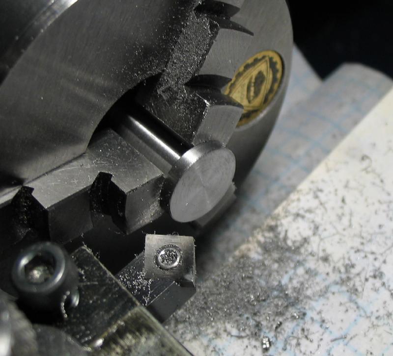
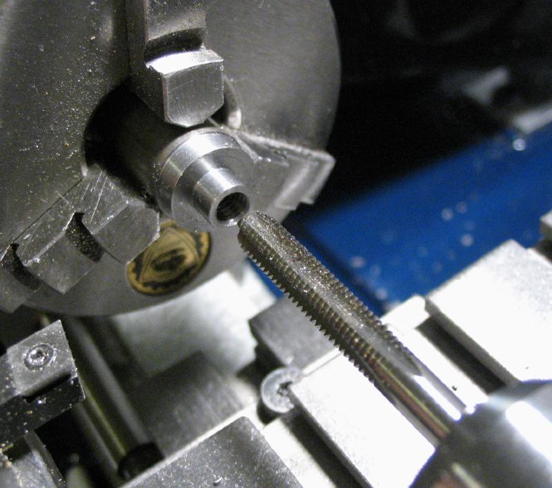
A pair of T-nuts are needed to secure the dividing head to the mount. They are made from 1/2" low carbon steel rod (12L14); turned to 12 mm, a length of 4 mm turned to 6.3 mm diameter, drilled 4.2 mm, tapped M5x0.8, countersunk and corners softened with a file, and parted off to leave a 2mm thick flange. It could then be reversed into a 1/4" collet and the parted side faced and countersunk.
|
|
|
|
|
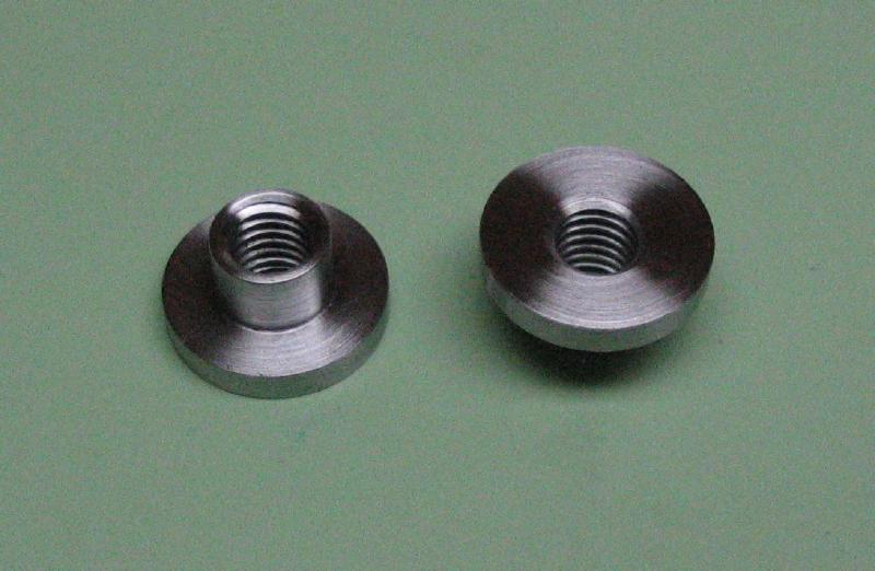
The nuts fit such that they remain below the surface of the mount. The usual square T-nuts are removed from the dividing head, but the threaded rods can be used.