Fitting a hinge to the case
The back bezel of the case needs to be opened daily for winding and occasionally for setting the hands. The bezel and center band snap together, but will need to be fit with a hinge, which requires a number of steps to carry out to completion.
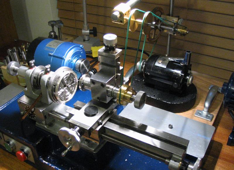
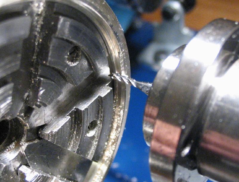
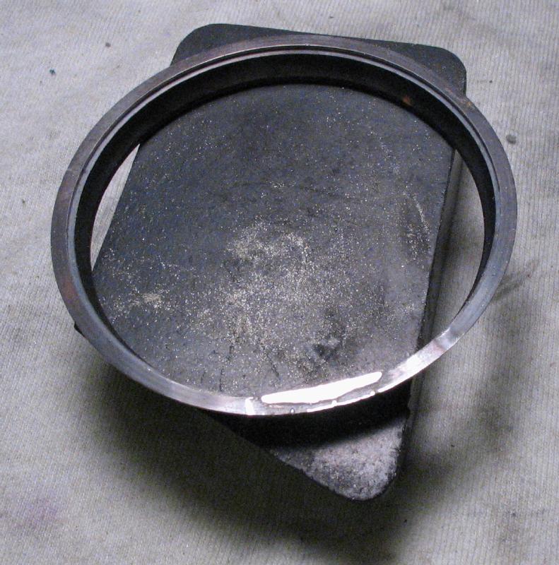
The center band was mounted on the 6-jaw bezel chuck with the headstock locked. The milling spindle was setup on the vertical slide and prepared for using with the auxiliary motor. I used a small, 1.5mm endmill to form a 7.5mm wide slot in the snap ring of the center band. A larger endmill could be used, but this was the first use of the recently finished pulley and auxiliary motor and I wanted to keep the torque demands light.
|
|
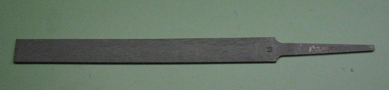
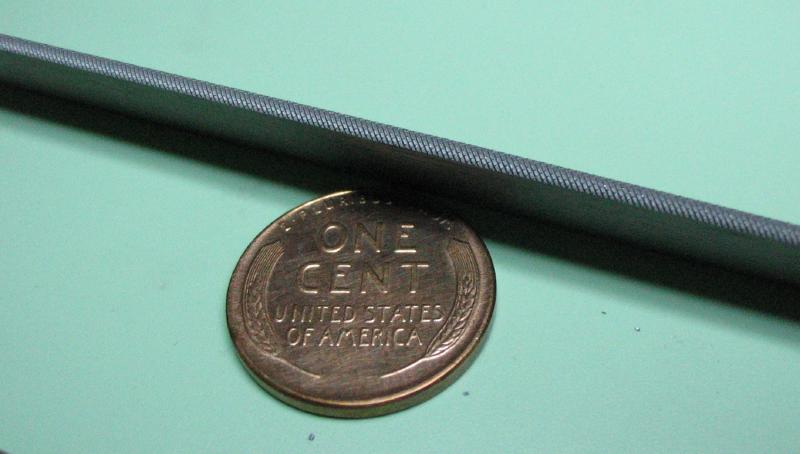
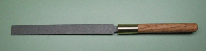
The groove is started with a Vallorbe joint file. This one is 1.5mm thick with round edges. The wider faces of the file are smooth, and the cutting edges are a No.2 Swiss cut. A handle for the file was made from 3/8" oak dowel rod fit with a collar made of brass tubing. The oak rod was drilled undersized and the file tapped in, using the taper of the tang to fix it in place.
|
|
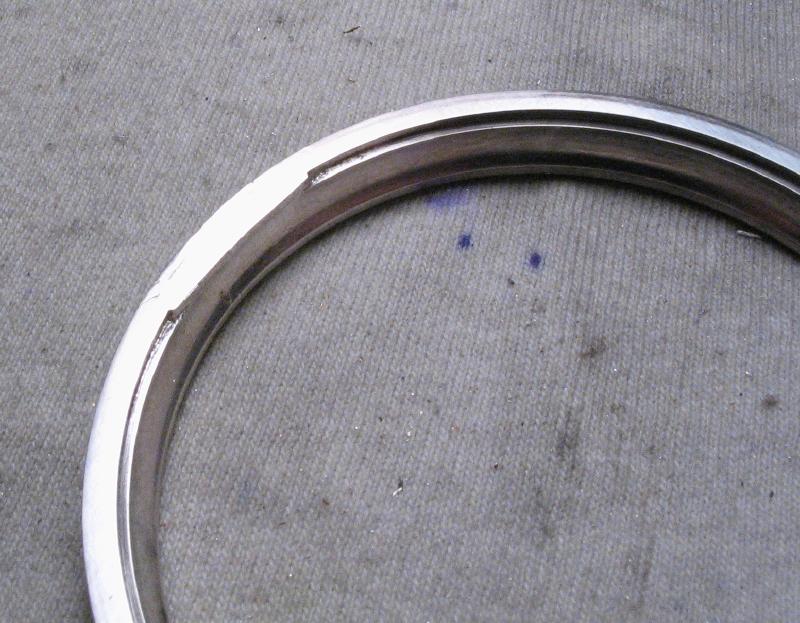
The notch milled in the snap ring above provides a guide for filing the groove in the center band. Daniels recommends a piece of leather to keep the work from moving while filing the groove, however, I fixed the work to the bench mat with some Rodico - crude but it works. The work was positioned near the edge of the bench top so that the file can be held level. Getting the groove started is perhaps the more difficult step, and then keeping the file level afterward. There is evidence of some aberrant file strokes. The No. 2 cut is a fairly light cut, so many strokes are needed to form the groove, but each one counts, especially if it is off track!

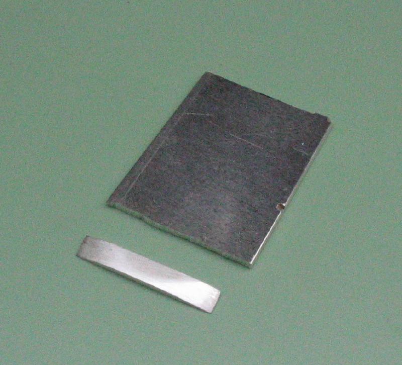
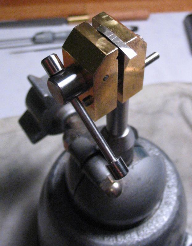
Before the groove can be filed in the bezel, the "bearer" must be installed. The bearer is a small strip of silver that resides in the snap groove that supports the hinge tube. A strip about 2mm wide was sawed off the end of a piece of 18 gauge (1.02mm) sterling silver sheet that it is about 16mm wide. It is intentionally taller than the snap groove at this time and needs to be shaped by filing in order to fit into the snap groove. This requires filing a slightly angled edge to match the snapping edge and a gradual curvature to match the snap groove diameter. It was held in the mini-vise and slowly brought to shape with frequent checks for fit.
|
|
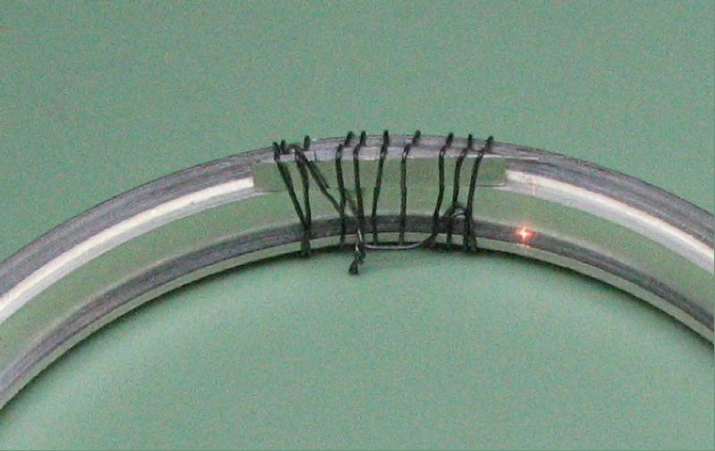
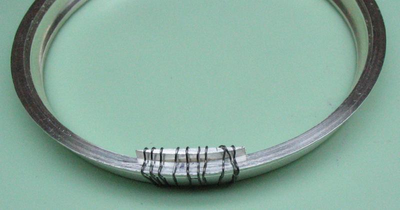
The bearer is wired into place with soft iron wire, which can then be made more secure by pressing the wire into corners and crevices. Two pieces of hard solder were used and the location for the bearer was chosen so that it is clear of the original joint of the bezel, which was secured with hard solder as well. Hard solder is used for bearer so that medium solder can be used for the hinge tube later on.
|
|
Fluxed and solder in place
|
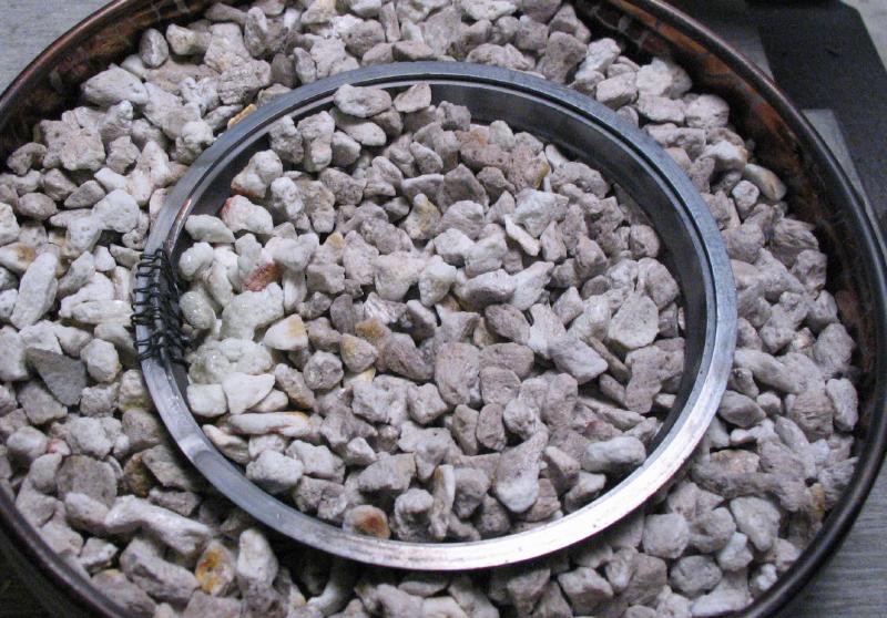
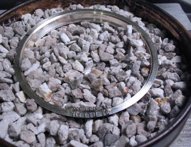
After heating
|
The bearer is then filed flush with the bezel.
|
|
|
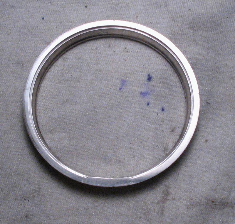
With the bearer now in position, the snap ring of the center band will need to be trimmed to accommodate it when snapping the bezel into place.
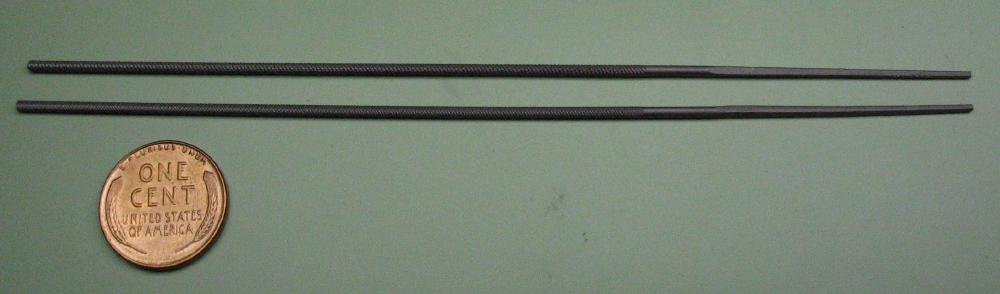
The opening for the hinge tube is enlarged with 1/16" (1.59 mm) diameter parallel round files. The pair shown are No. 0 and No. 2 Vallorbe files.
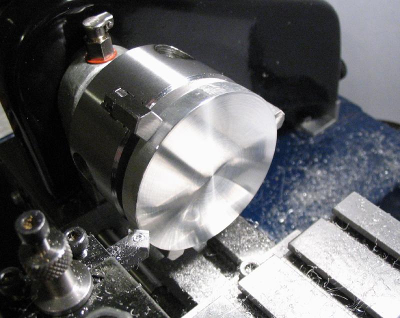
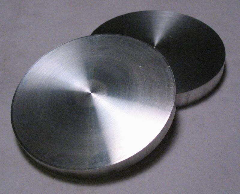
The case band and back bezel need to be clamped together while broaching the hinge groove. Two discs were made from 2-3/8" aluminum (type 6061) rod. Sections were sawed off and faced on either side on the lathe.
|
|
|
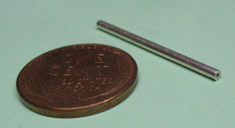
The material used for the hinge is heavy wall (0.020") sterling silver tubing (outer diameter : 1.6mm, inner diameter : 0.6mm).