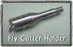
Fly-Cutter Holder
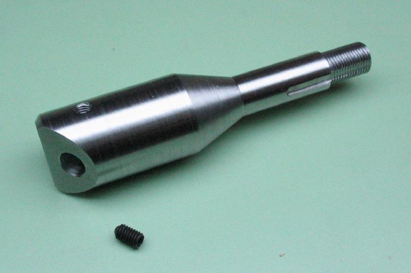
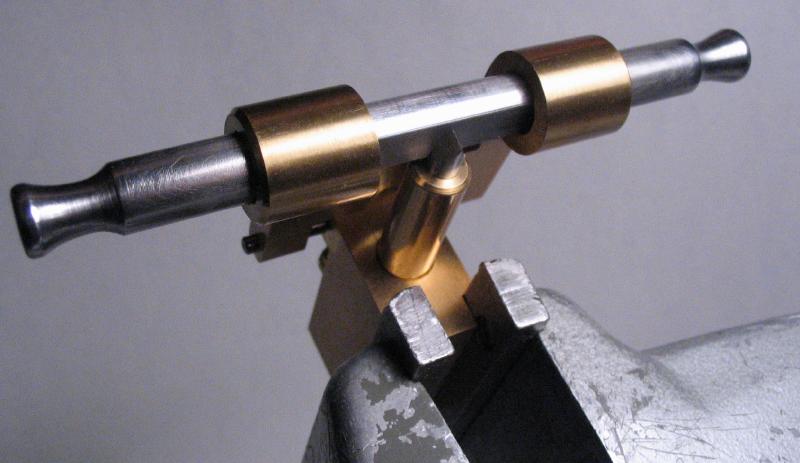
A holder for a fly-cutting tool bit is shown below. There are various types of fly-cutter and ways of holding them depending on the operation needed. The tool described on this page is intended primarily for face-milling relatively large areas. I am following the basic design in John Wilding's "Tools for the Clockmaker and Repairer - How to make and use them." My changes include a collet-style shank, M3 set screw, and a 5mm diameter tool bit.
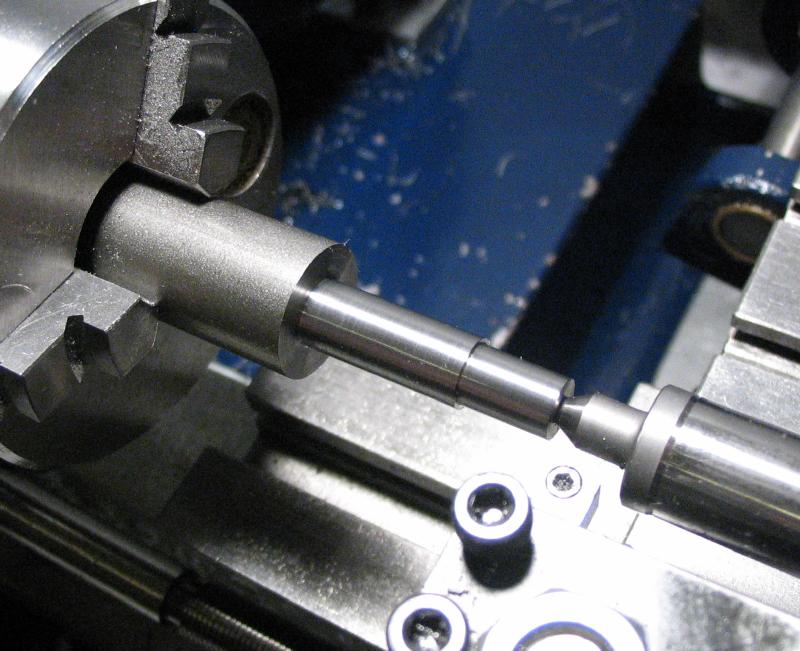
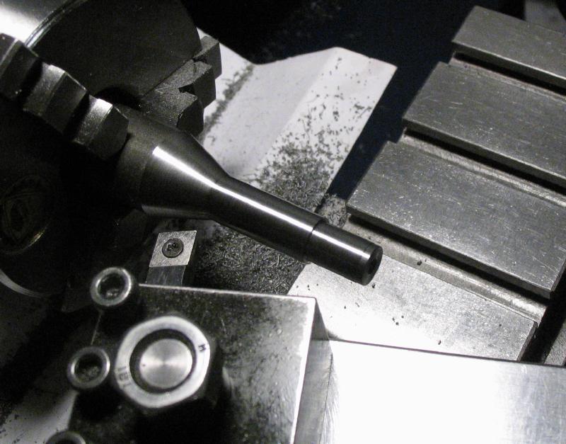
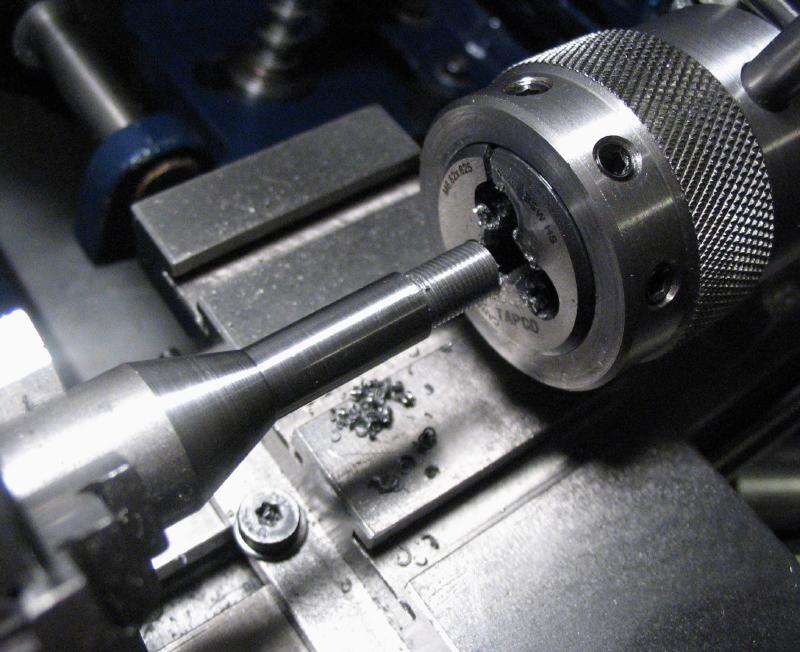
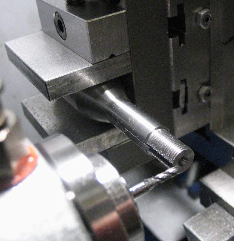
The work was started from 5/8" cold roll steel (12L14), with a starting length a little of 60mm. The collet end as started first. The ends were faced and one end center drilled using the steady-rest for support. The body and thread diameters turned, the 20 degree taper turned with the compound slide, and the threads cut with a B8 die. The 2mm key slot was milled with the work mounted in the vise and vertical slide.
A holder for a fly-cutting tool bit is shown below. There are various types of fly-cutter and ways of holding them depending on the operation needed. The tool described on this page is intended primarily for face-milling relatively large areas. I am following the basic design in John Wilding's "Tools for the Clockmaker and Repairer - How to make and use them." My changes include a collet-style shank, M3 set screw, and a 5mm diameter tool bit.
The work was started from 5/8" cold roll steel (12L14), with a starting length a little of 60mm. The collet end as started first. The ends were faced and one end center drilled using the steady-rest for support. The body and thread diameters turned, the 20 degree taper turned with the compound slide, and the threads cut with a B8 die. The 2mm key slot was milled with the work mounted in the vise and vertical slide.
|
|
|
|
|
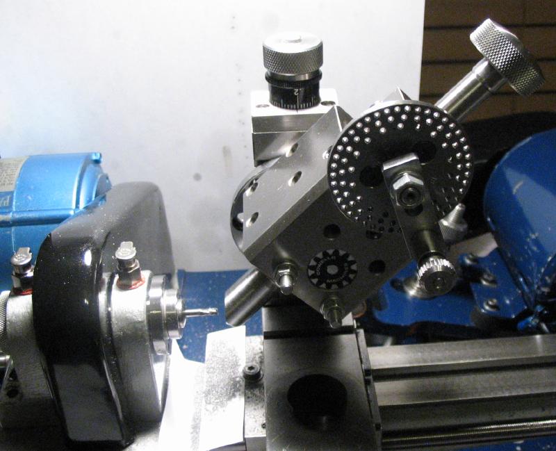
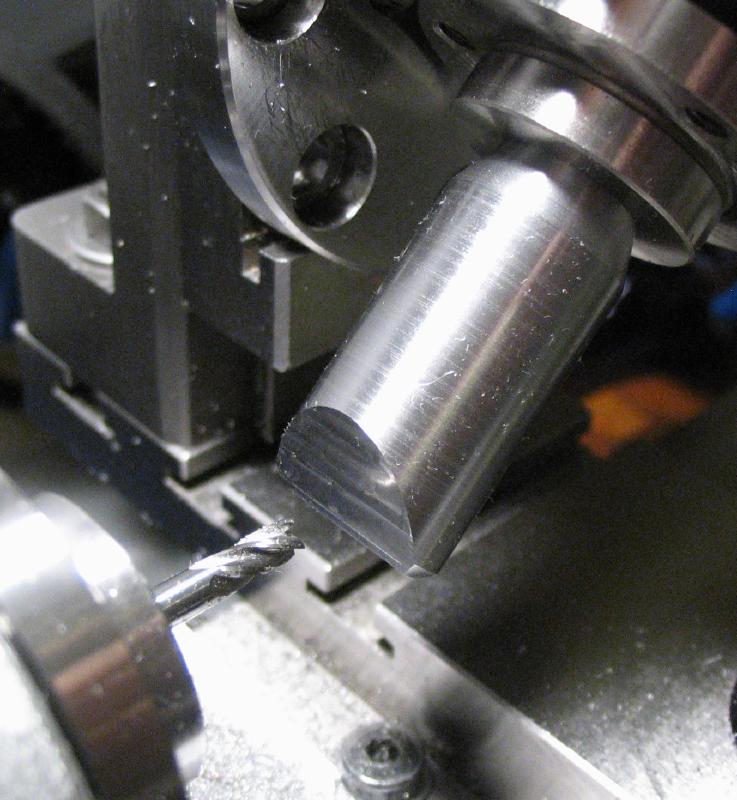
The work was mounted directly in the headstock to turn the outside diameter and the work then moved to the dividing head that was attached to the vertical slide using the adjustable mounting plate to allow it to be set at a 45 degree angle. An endmill was used to form a flat recess.
|
|
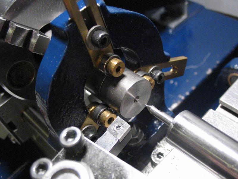
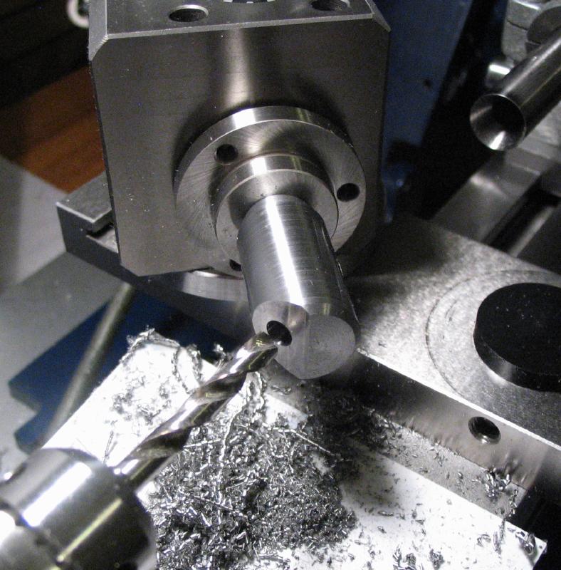
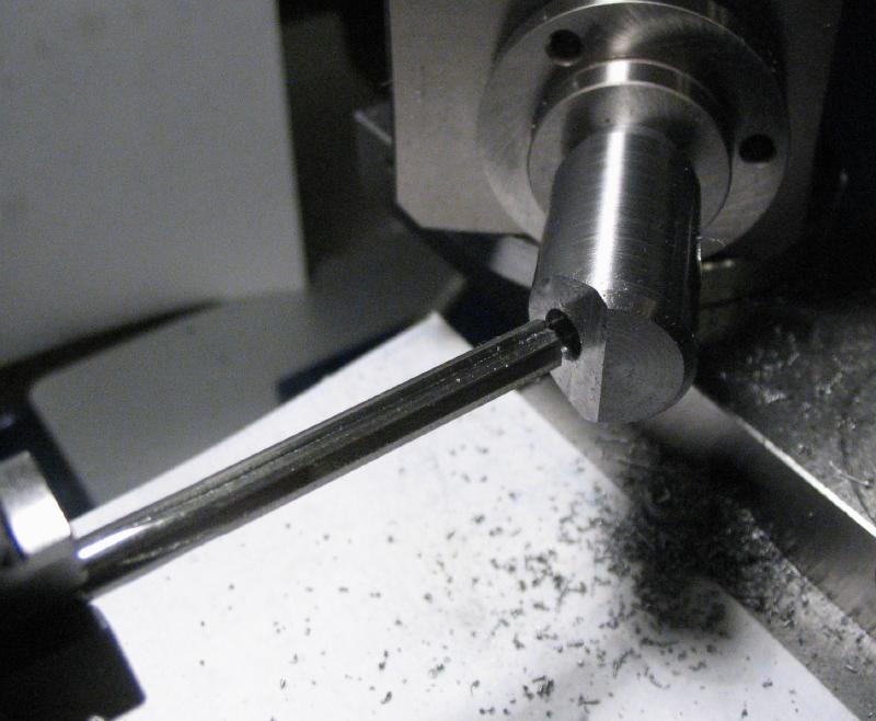
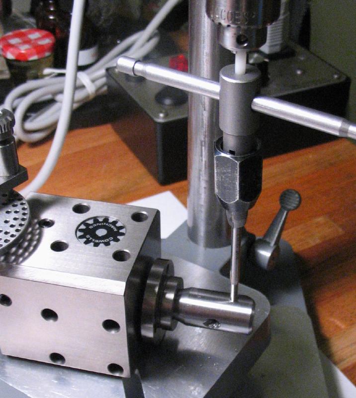
The dividing head and mounting plate were moved to the cross slide and the 45 degree angle re-found. This is to ensure the hole will be on center height, and is a little more rigid than the setup used above for the milling step. The hole was drilled 4.7mm and reamed 5mm.
|
|
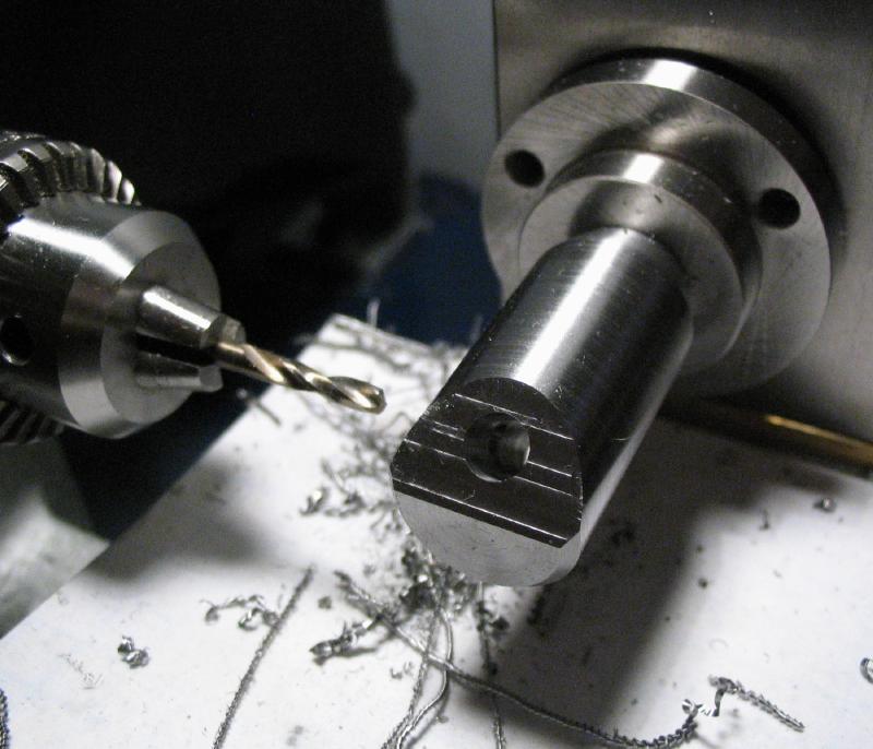
The work was rotated 90 degrees in the dividing head and the head itself rotated to be perpendicular to the headstock. A 2.5mm hole was drilled to tap M3x0.5 for a set screw.
|
|
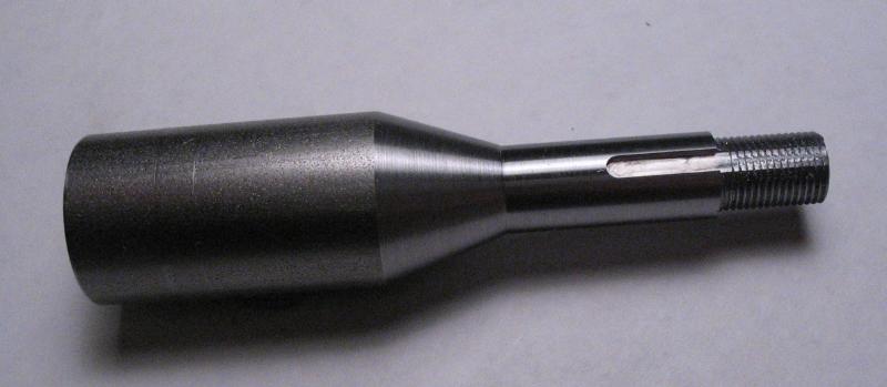
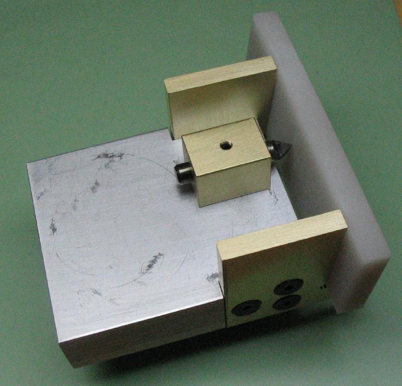
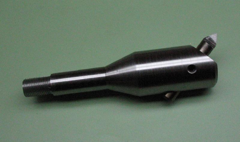
The holder is essentially complete at this point.
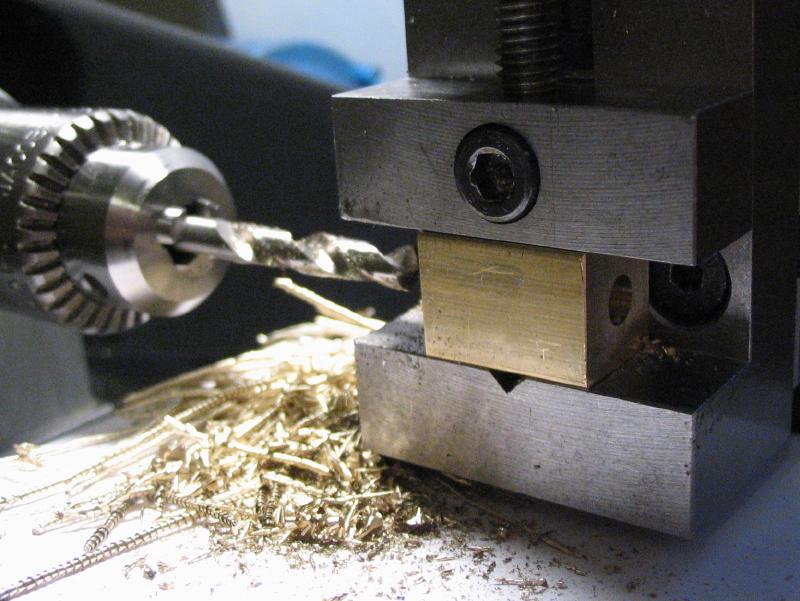
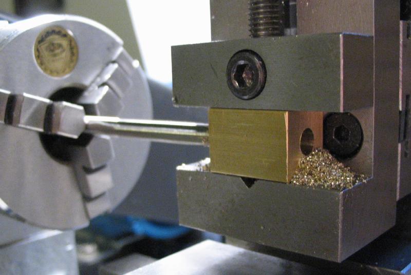
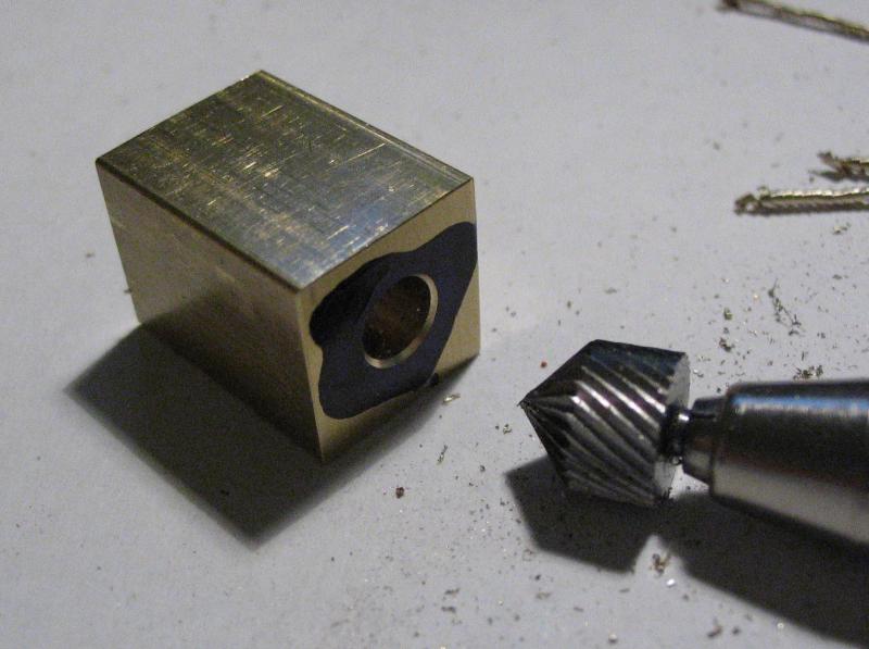
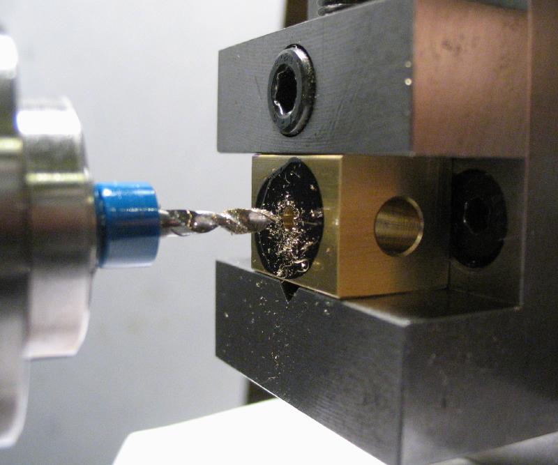
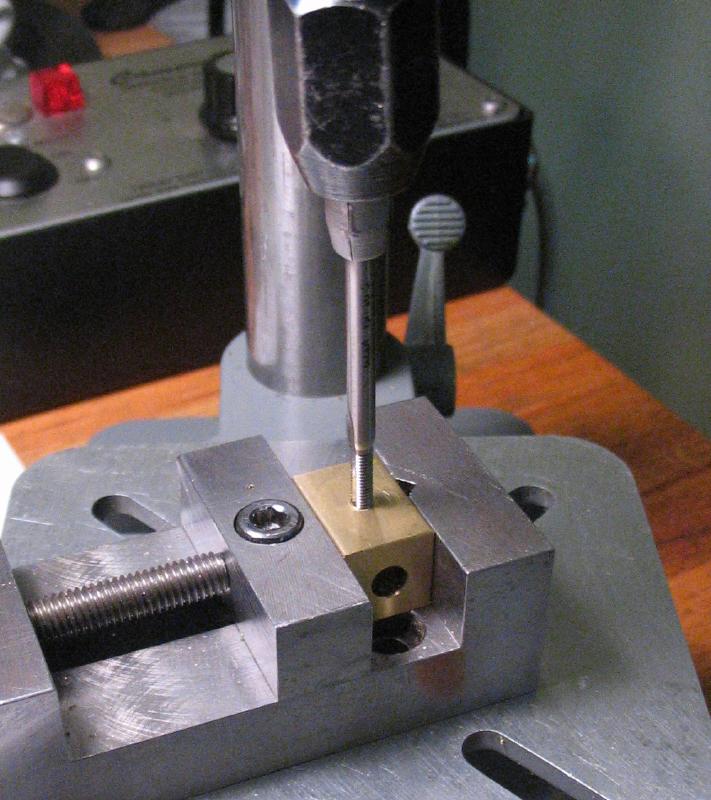
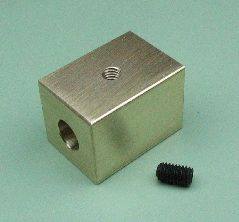
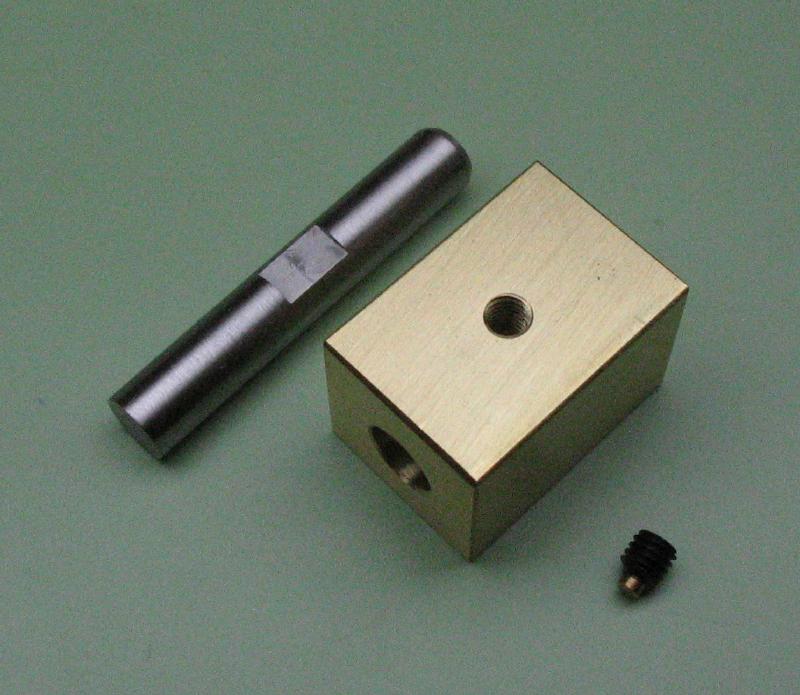
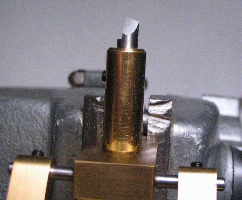
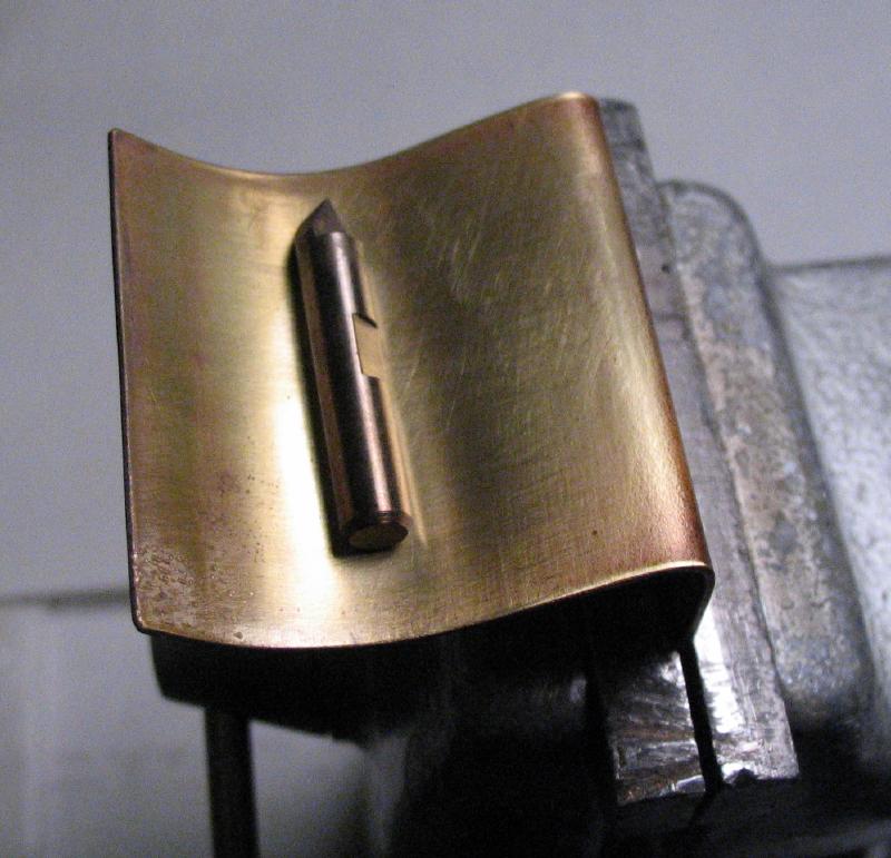
A holder was made from 1/2" square brass bar. A length of about 20mm was sawed off and the end faces then milled flat. A central hole was drilled and reamed 5mm, and the openings countersunk to remove burs. Centered on the top face, the position for a set screw was drilled and tapped M3.
|
|
|
|
|
|
|
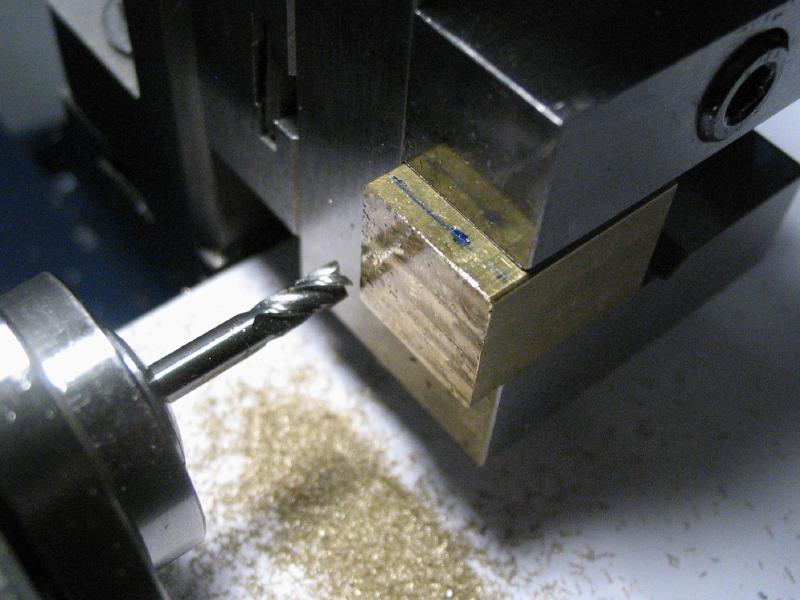
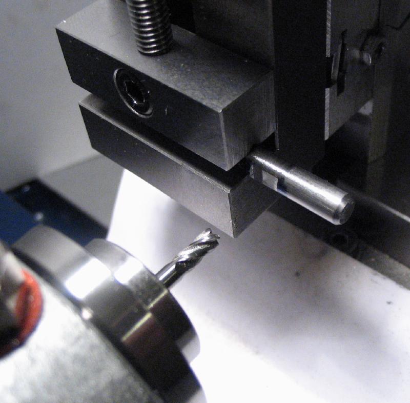
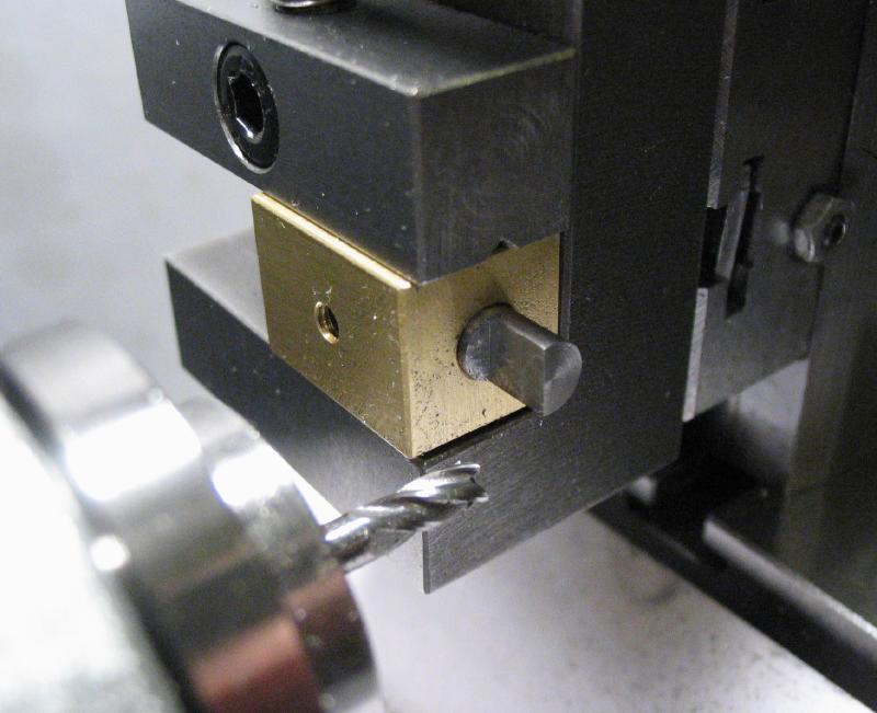
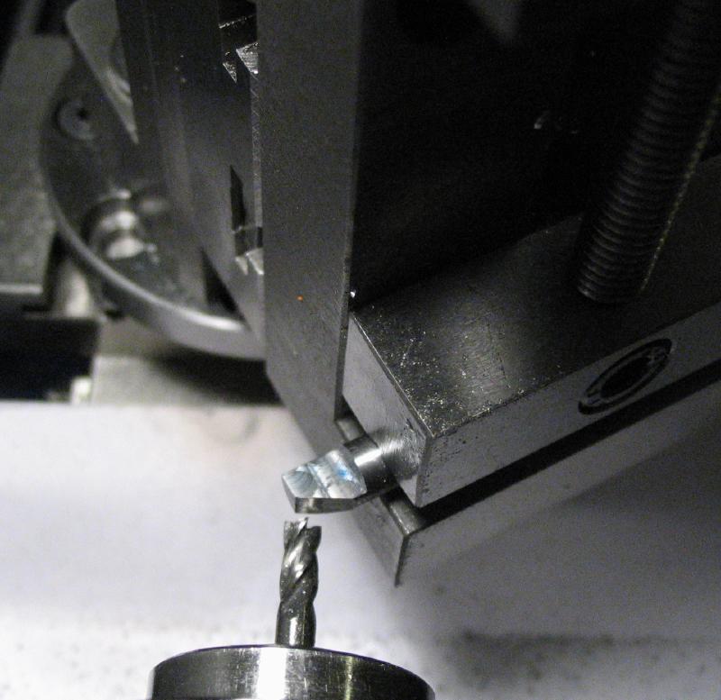
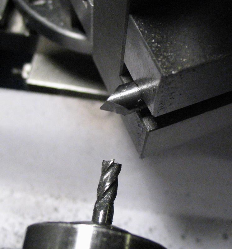
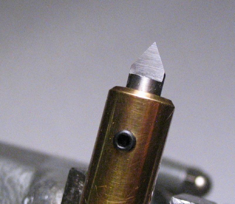
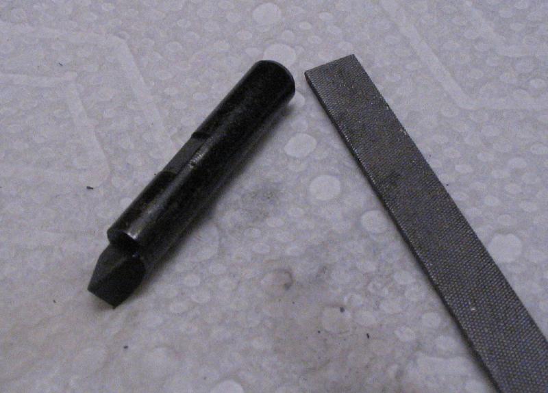
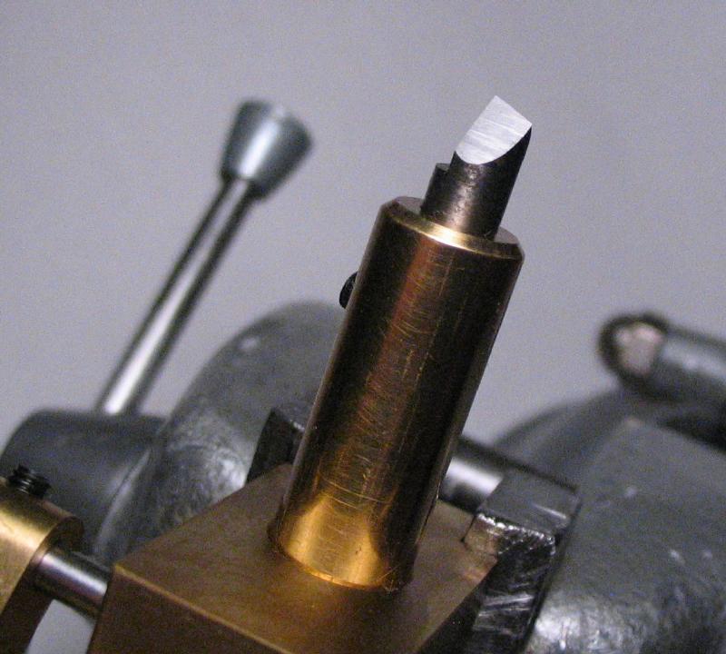
A flat was milled onto a length of 5mm drill rod. The flat mates with the set screw of the holding block made above, which was then used to hold the rod for milling the top face of the cutting end. The vertical slide was then mounted on the adjustable plate and set over 30 degrees and the rod held in the vise rotated about a 10 degrees while milling the opposing front faces.
|
|
|
|
|
|
|
|
|
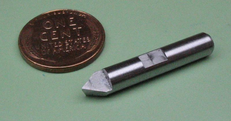
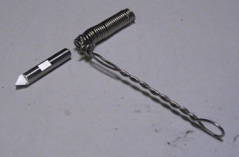
A wire basket was formed to hold the bit during the hardening process, the hardness checked afterward with a file, and the bit tempered on a piece of brass and stopped once a color change was observed. The final smoothing of the cutting edges was carried out with the honing jig as above, and the tip given a very small radius using another type honing jig.
|
|
|
|
|
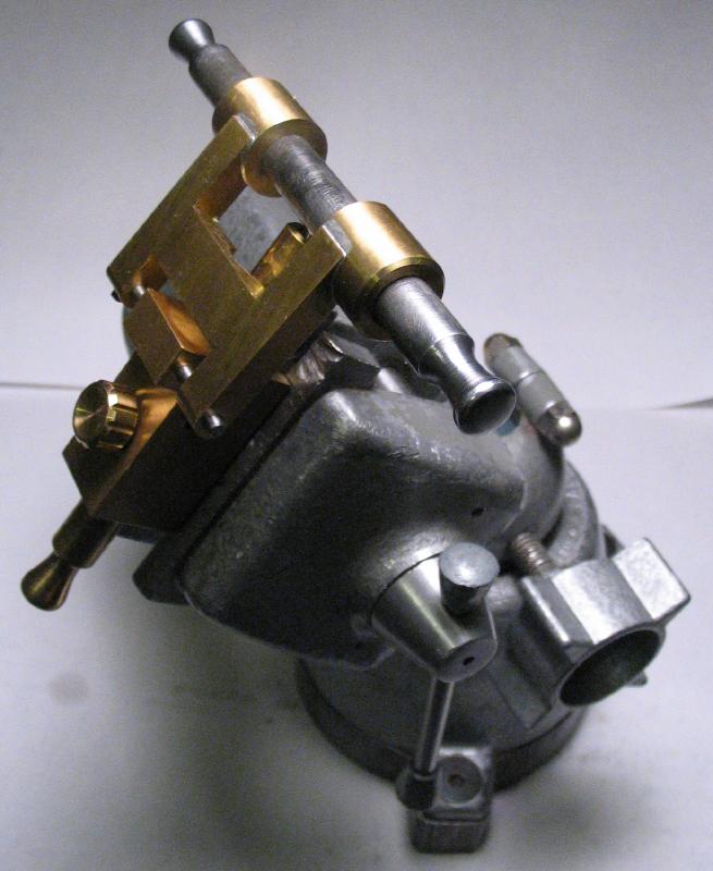
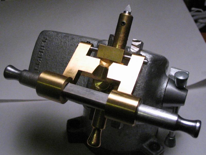
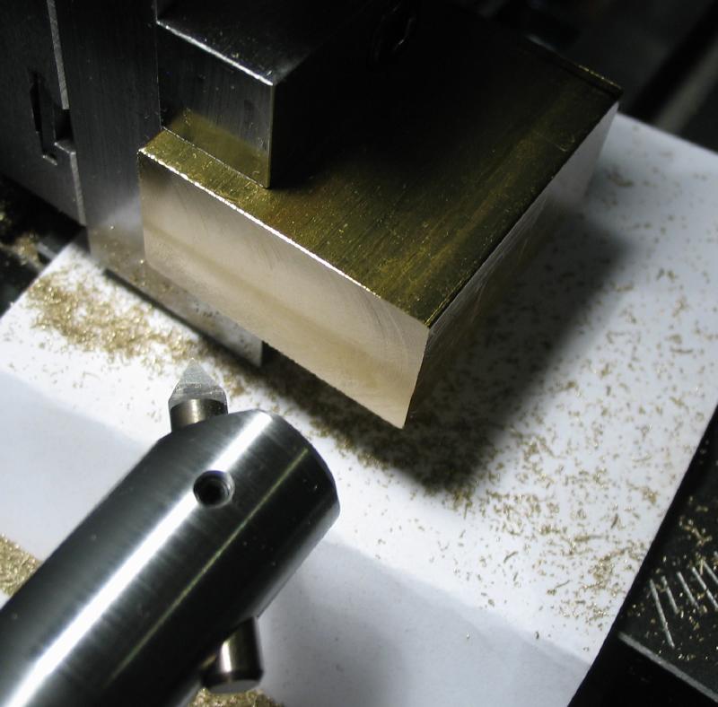
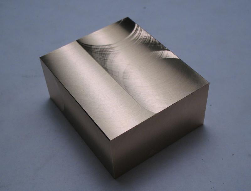
The tool was assembled for its first task, which was squaring up a piece of brass bar. It was progressively milled with the fly cutter on each side, and some experiments attempted with speed and feed. A good finish is certainly possible, especially compared to using multiple passes with a small endmill.
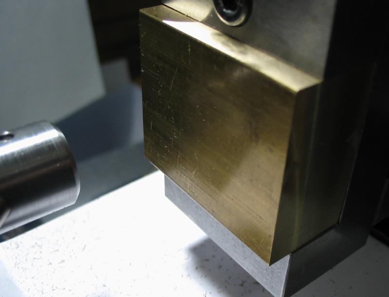
Before
|

After
|
|
