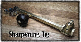
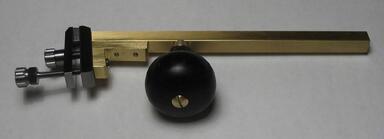
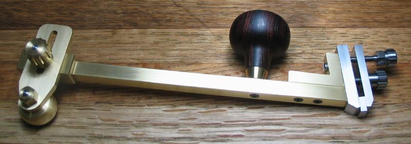
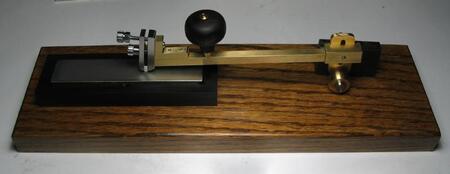
A jig for sharpening insert-type lathe tool bits is described in the November 2000 issue of Model Engineer's Workshop.
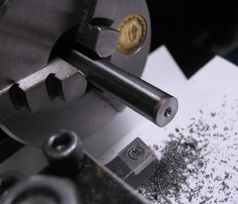
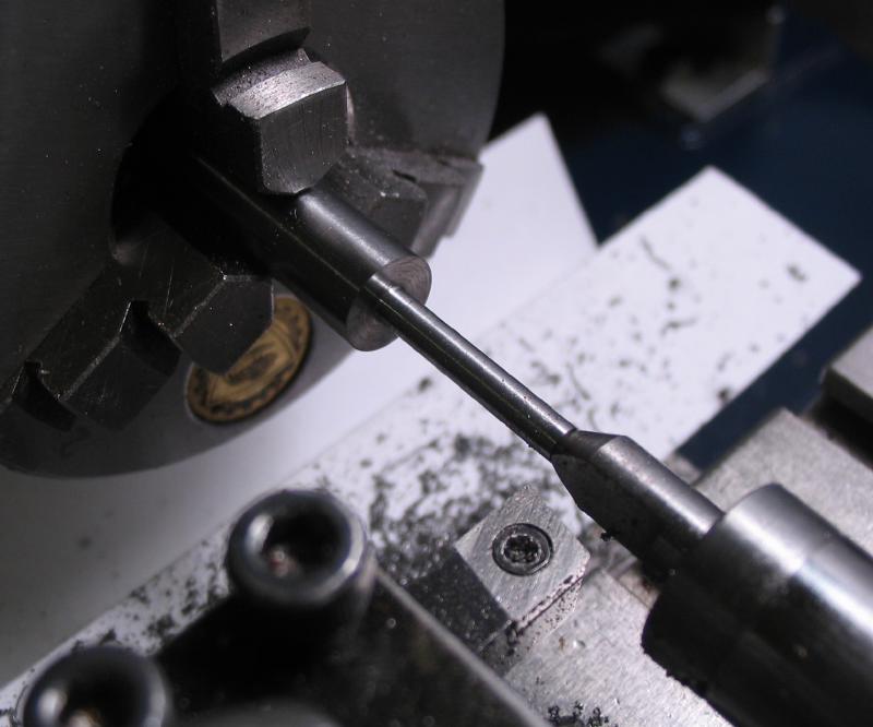
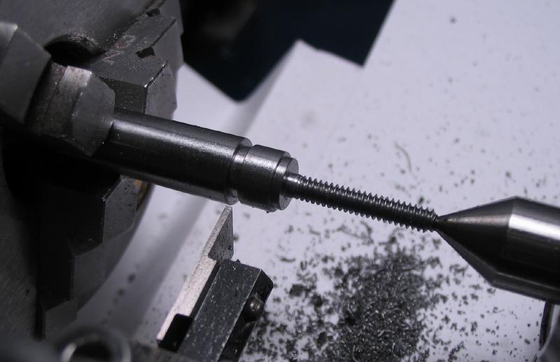
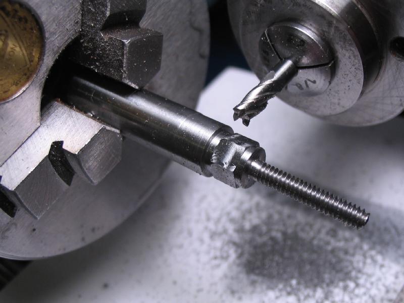
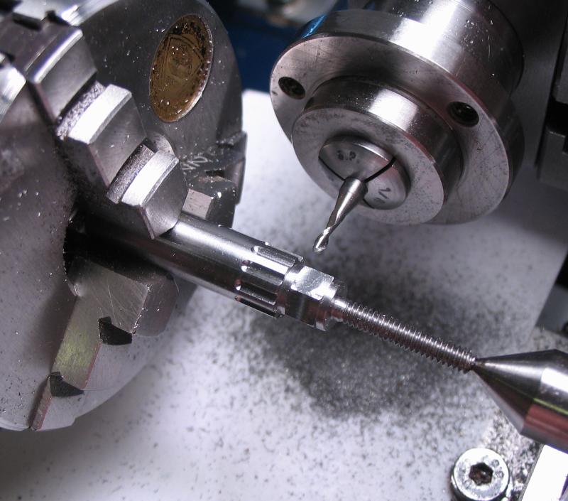
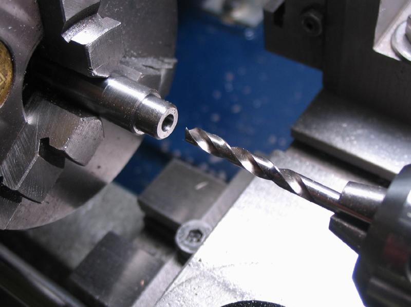
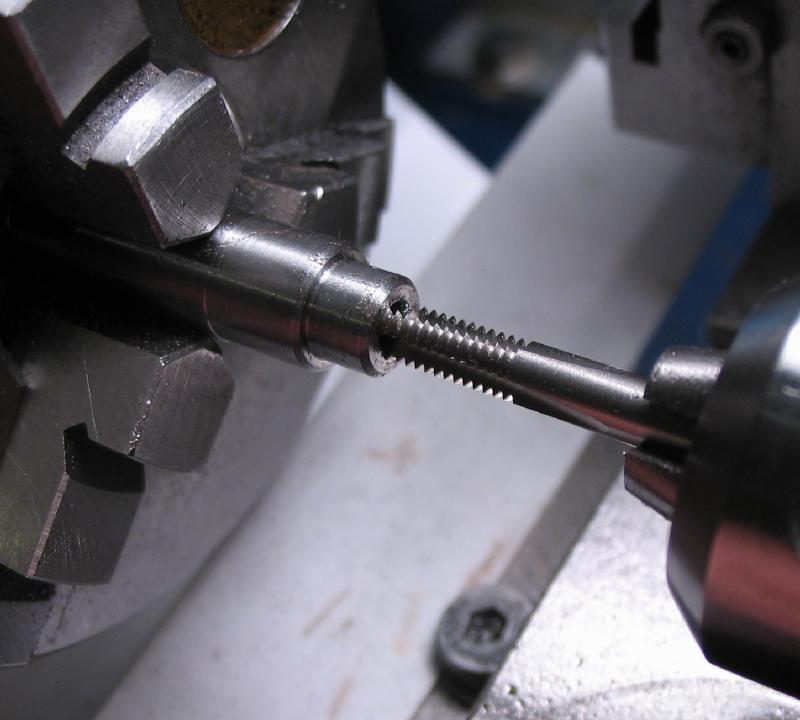
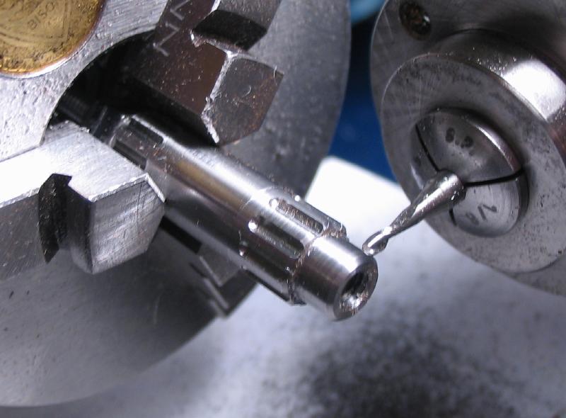
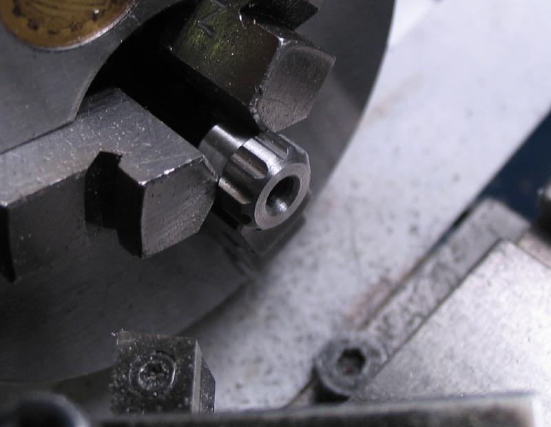
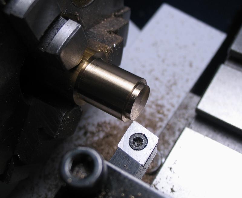
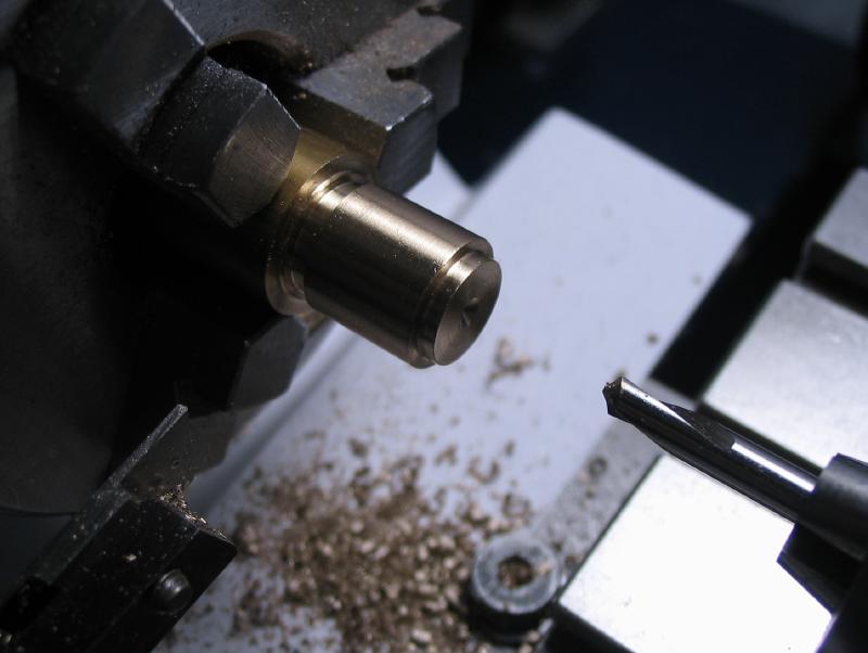
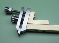
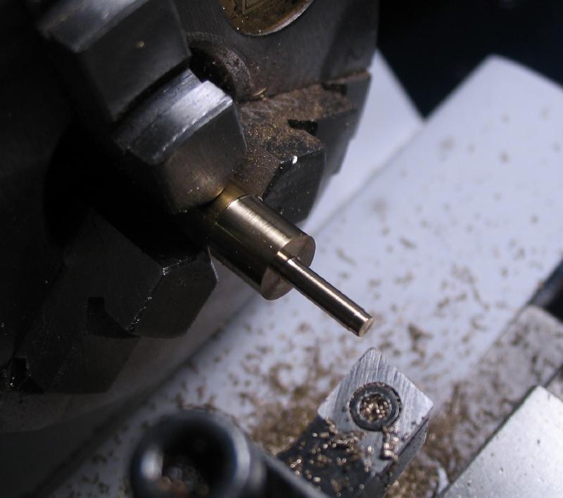
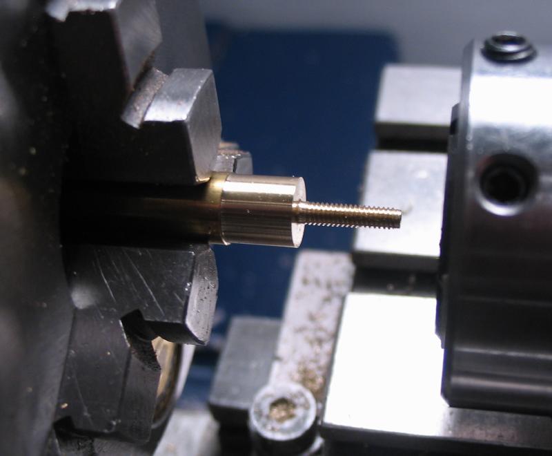
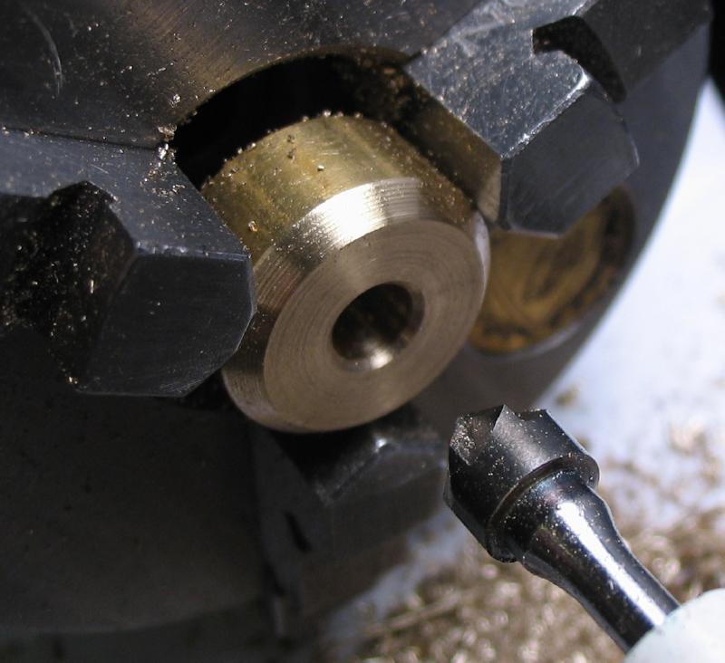
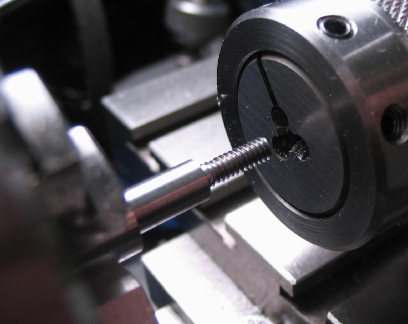
The jig holds the inserts with a clamping finger-type of arrangement. The counter screw was started first, and is made from 5/16" steel rod (12L14). The steps are shown, and include center drilling, turning and threading #4-40, and a parting bit used to form slots and a 6mm width hex and ten grooves milled for tightening by hand or wrench as necessary. I changed my mind and re-chucked in the 4-jaw for reducing the overall size of the head, and turning away the center drilled hole, After parting, the top was turned and chamfered. The screw may be reduced in length later on, since very little range of adjustment will likely be necessary.
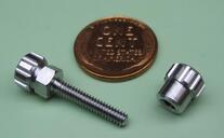
A thumb nut was made in a similar manner to thumb screw above, and was, in fact, made on the reverse end of the same steel rod at the same time, however, is threaded #6-40.
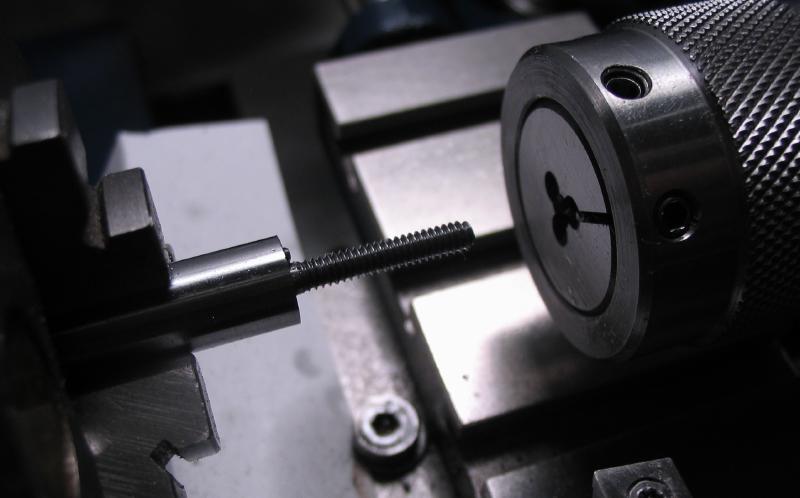
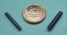
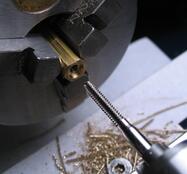
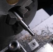
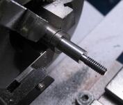
Two lengths of threaded rod were needed, #4-40 and #6-40, to match the thumb nut above and the brass-headed thumb screw made below. The threaded rod was made from 1/4" steel rod (12L14), turned with tailstock center support and threaded with a die. The rod is parted off and the ends rounded over with a cup bur.
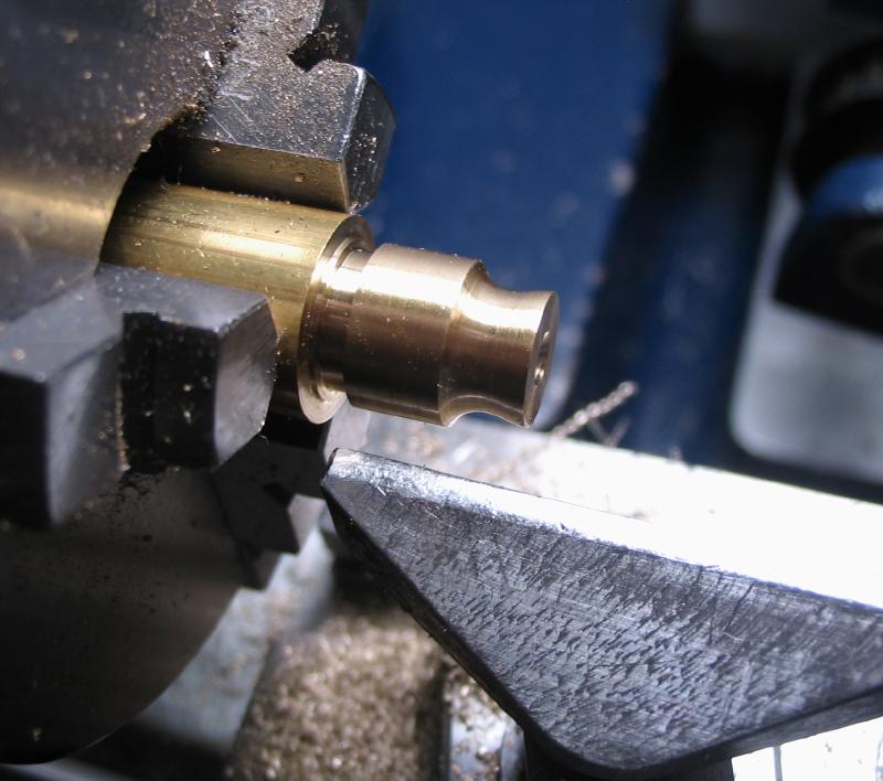
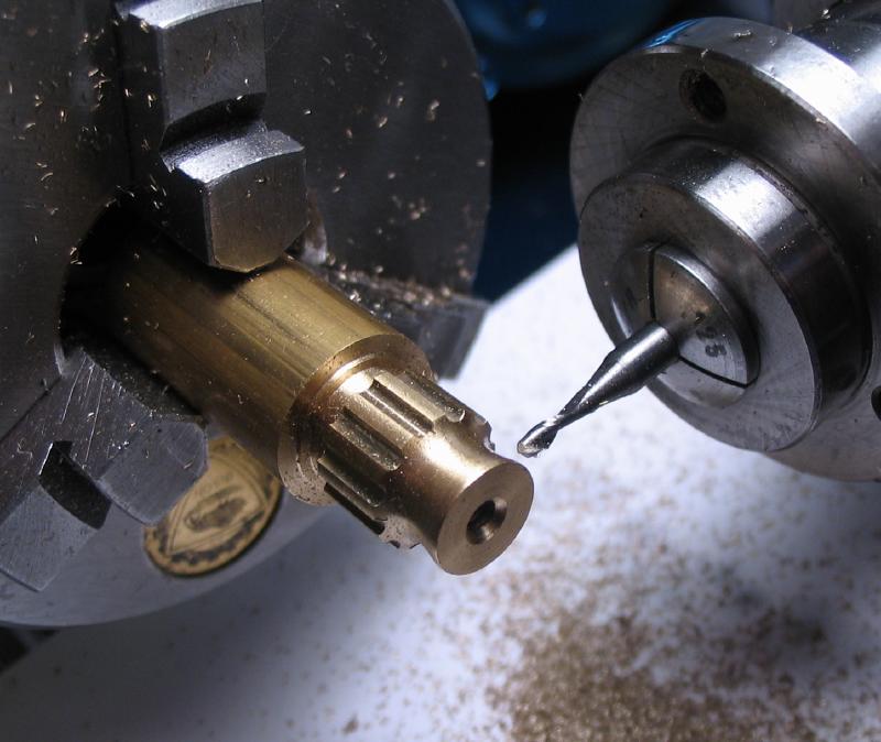
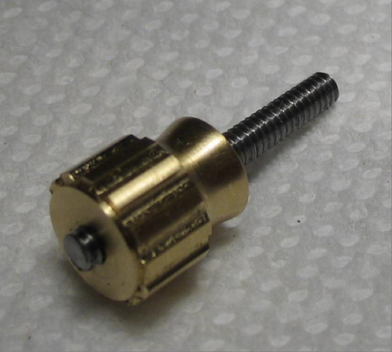
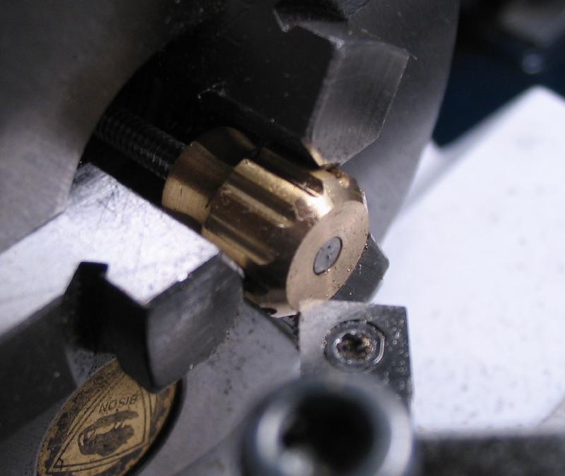
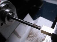
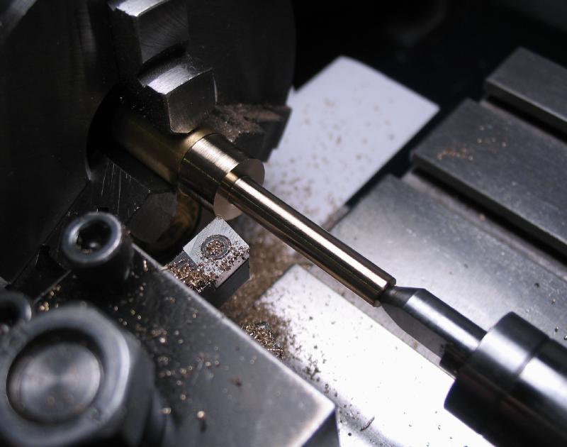
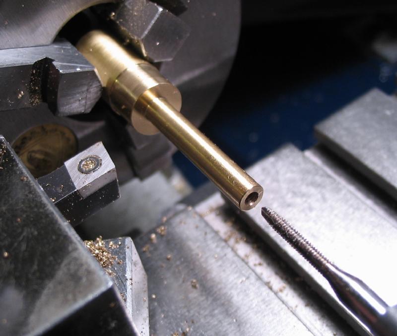
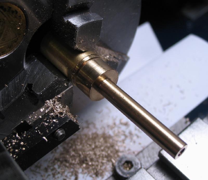
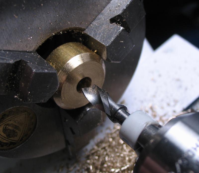
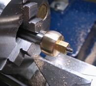
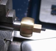
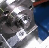
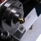
A locking screw will be needed for the roller bracket, and was made in two parts, the threaded rod above and a brass head. The head is made form 1/2" brass, turned to 10mm, drilled and tapped #4-40, and the tip turned to about 7mm. A rounded waist was turned by hand with a graver made from 1/8" drill rod. The head was milled with 12 grooves and parted off. The threaded rod wasn't quite long enough and another was made; I initially planned on a blind hole in the brass head, but did not have a bottoming tap in this size, so a through hole was needed. The threaded rod is locked in place with Loctite blue 'thread-lock' adhesive. After allowing the Loctite to cure overnight, the surplus thread and top face of the knob were turned flush and the corner chamfered.
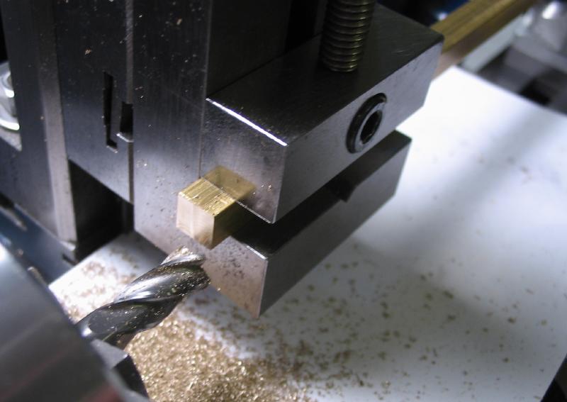
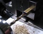
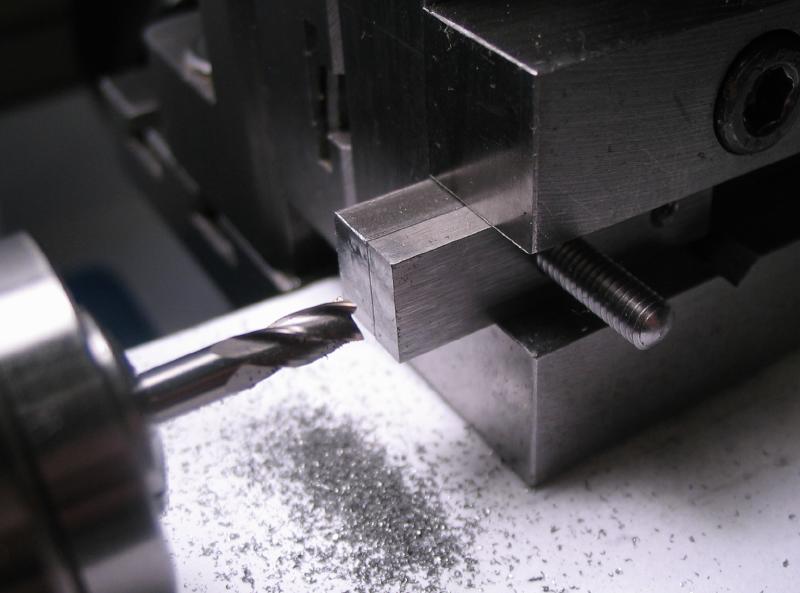
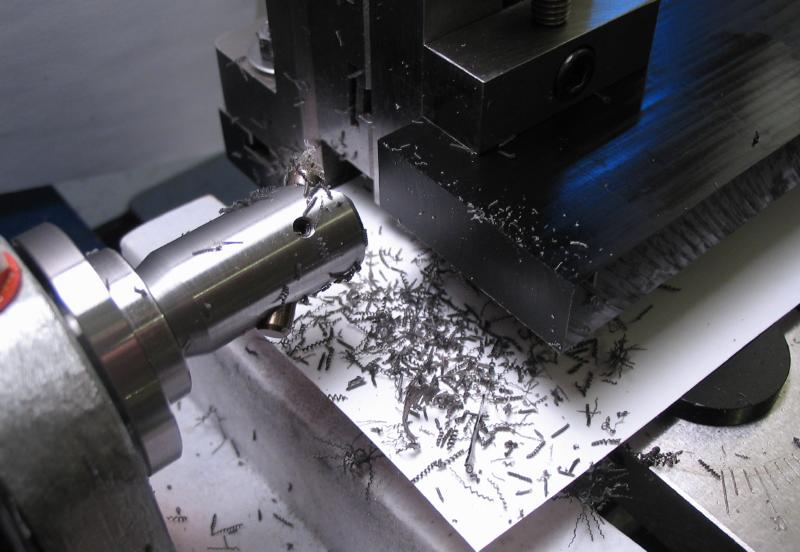
Many of the parts of the jig were made from bar stock, so planning ahead, the same lathe setup was used for milling the ends of all the stock shown to square the sawed edges.
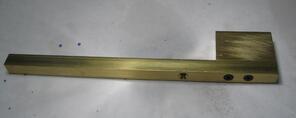
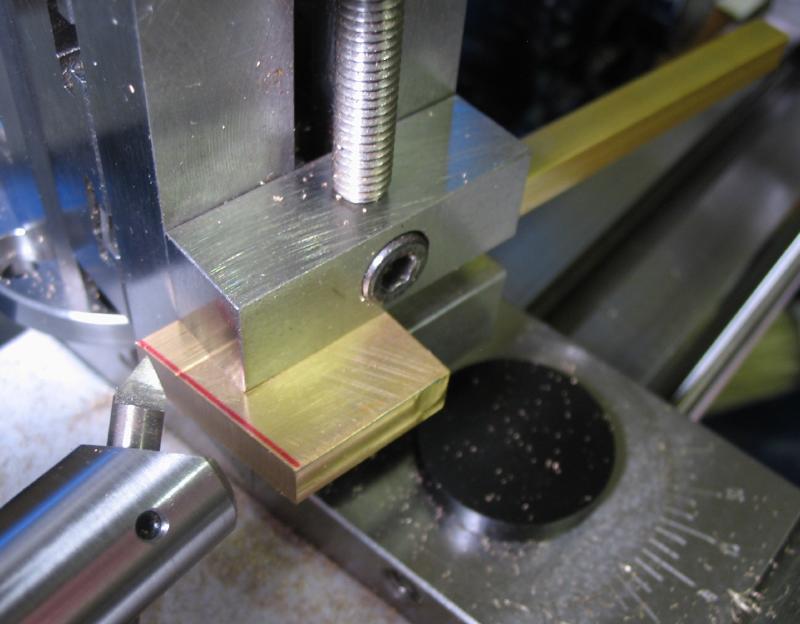
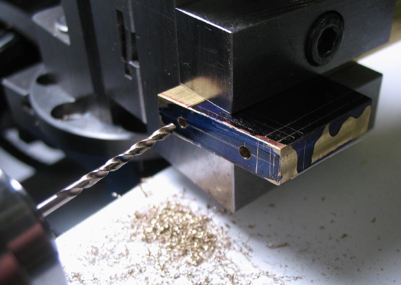
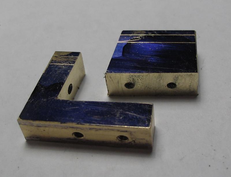
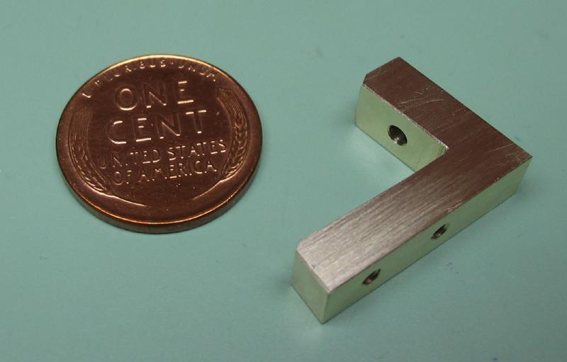
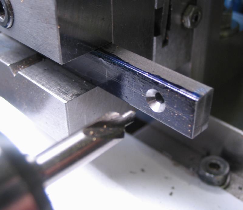
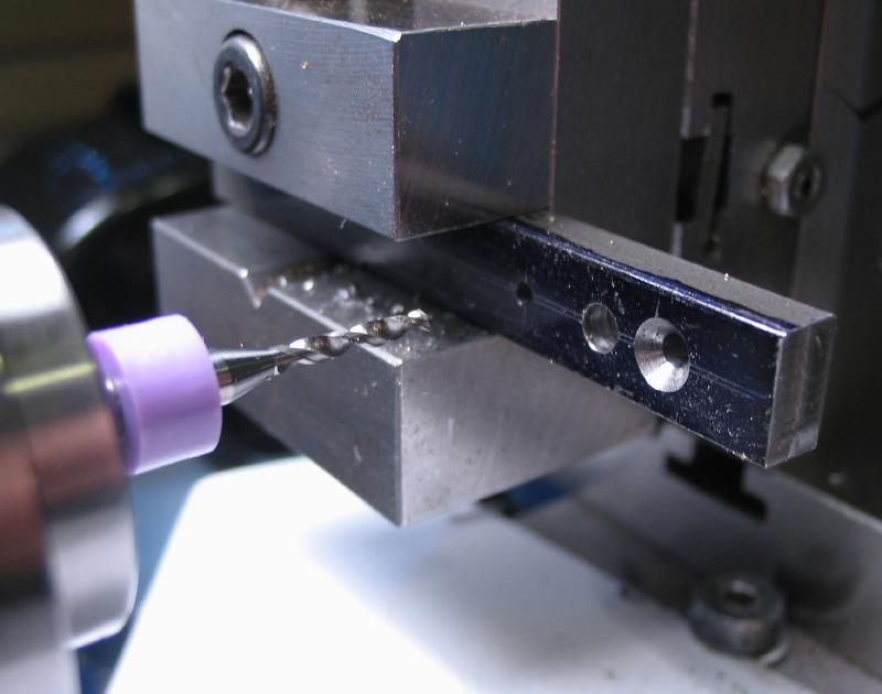
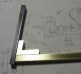
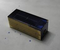
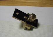
These pieces of stock need to be fit to one another, and brought to shape one step at a time. An L-shaped corner bracket will support the finger clamp and attach to the jig. It was started from a piece of 1/4" brass plate scrap that was milled to a rectangular shape and fit to a length of 1/4" square brass rod with two M2 countersunk head screws. A 90 degree #2 countersink drill was used to form the screwhead sinks. The bracket was drilled and tapped M2x0.4 to match. A third screw position in the square bar is provided for the handle post.
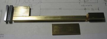
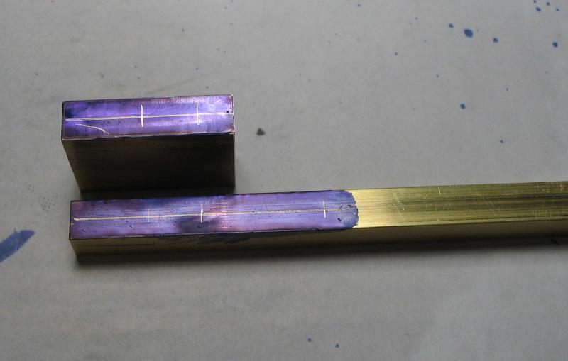
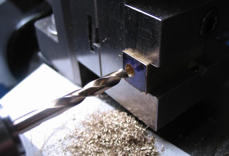
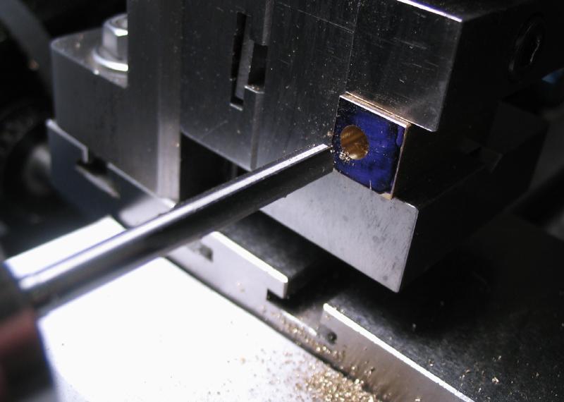
The 1/4" square bar is attached on the other end to a short length of 3/8" square bar, this acts as the guide for the roller bracket. The two bars will be joined with a 5/32" diameter plug and soldered together later. First, each piece of bar was drilled and reamed to fit the plug.
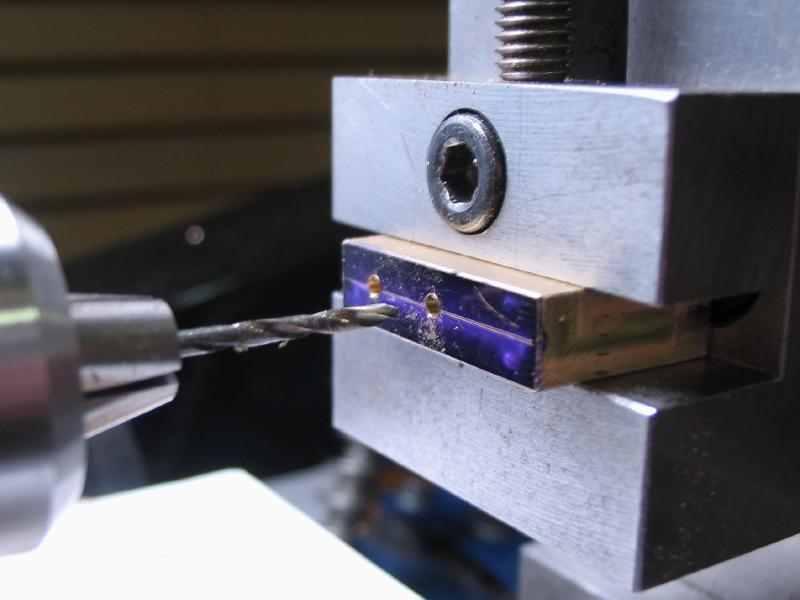
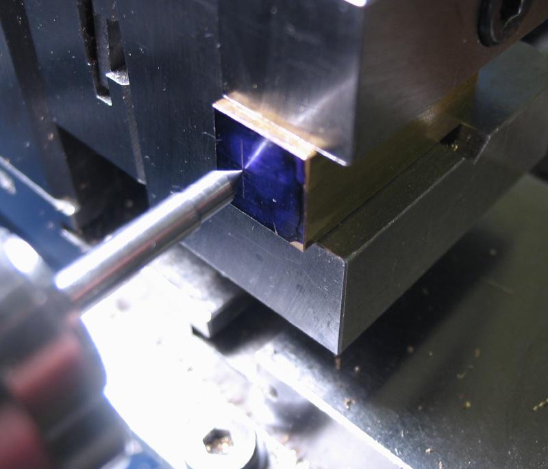
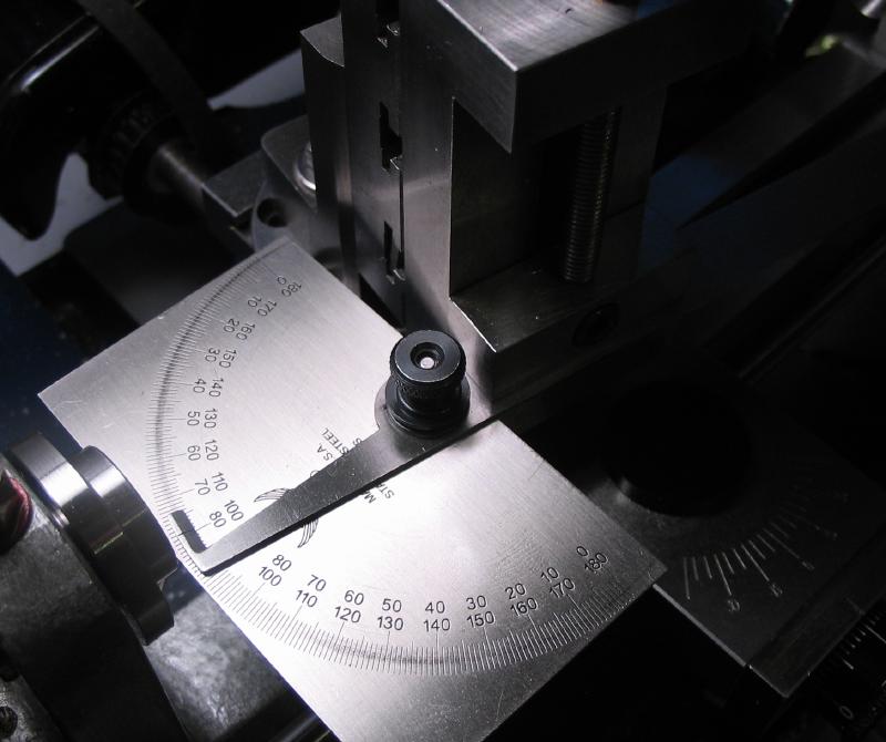
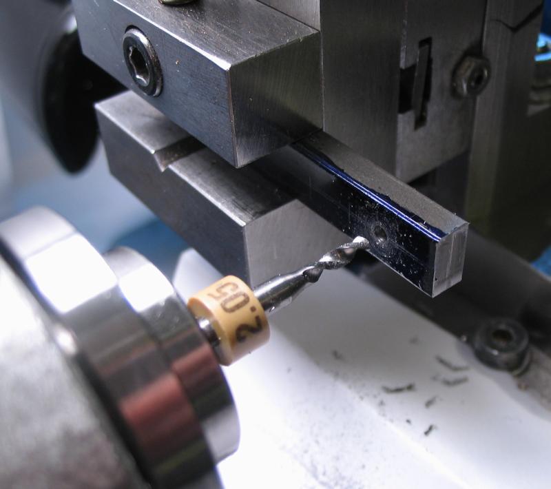
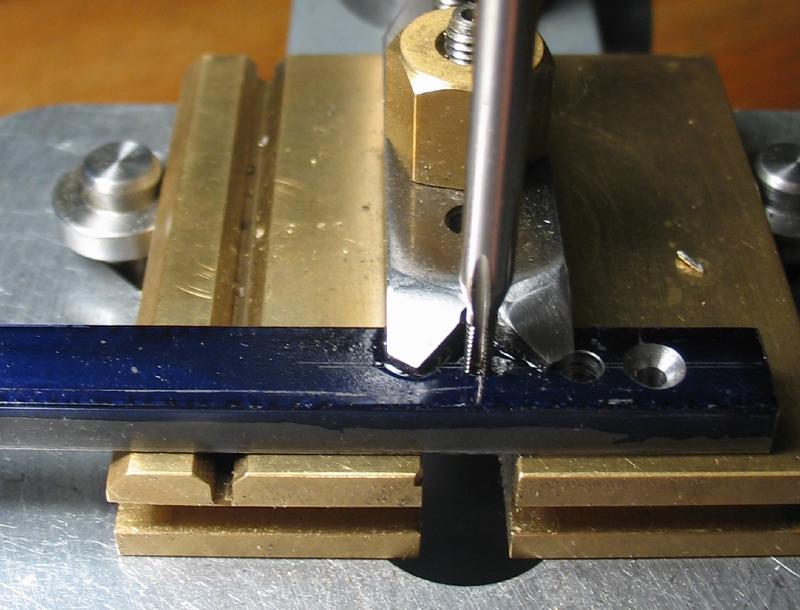
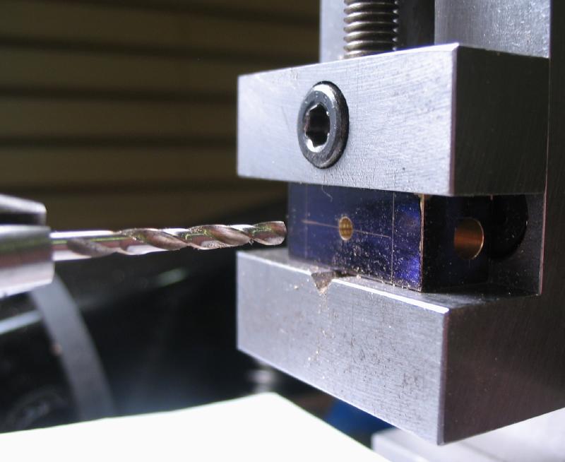
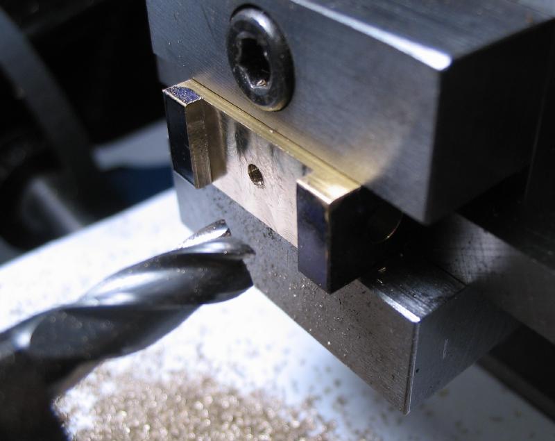
The vertical slide and vise were set up at 80 degrees and the assembled bar and bracket milled with a fly cutter. The positions for the two screws were drilled - the one in the bracket being a 2.05mm clearance hole and the hole into the bar was 1.6mm for tapping M2. The tapping was carried out on the lathe to take advantage of the angled offset, but was a somewhat precarious arrangement.
The bracket was sawed out and the filing machine and emery paper were used to improve the finish.
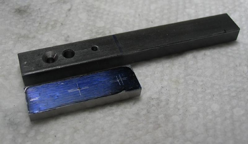
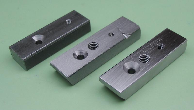
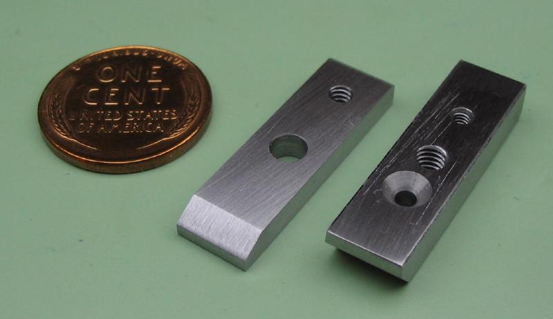
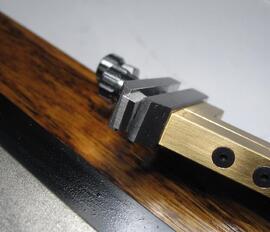
The lower part of the clamp was made from 5/16" x 3/16" water hardening (W1) steel bar. The positions were drilled for a M2 countersunk screw, the #6-40 threaded rod, and to tap for the upper M2 slotted screw.
The upper part of the clamp was made from 5/16" x 1/8" oil hardening steel bar. The drilling and tapping were carried out at the drill press, and position for a clearance hole for the #6-40 threaded rod and tapped hole for the #4-40 counterscrew are needed. A test fit is shown and the lower section was reduced in length and was aligned with the upper section using the threaded post and the ends of both pieces milled flush.
The corners were relieved by milling with the work held at suitable angles. The surfaces were improved with emery paper. An acceptable lower section for the clamp was found on the third attempt; the first lacked good alignment with the mounting screws discontinued at that stage and the second suffered a serious gouge with a hacksaw blade after nearly complete and although functional it was too deep to file or polish away. I show the more convenient method of production in the steps above that starts with an extended length and then parting off when complete, obviously taking care when sawing...
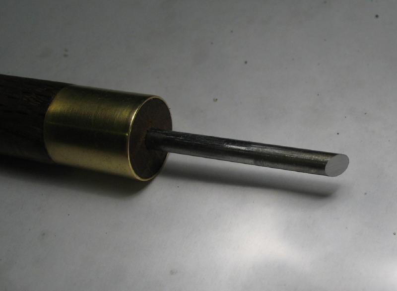
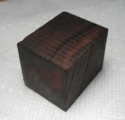
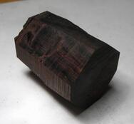
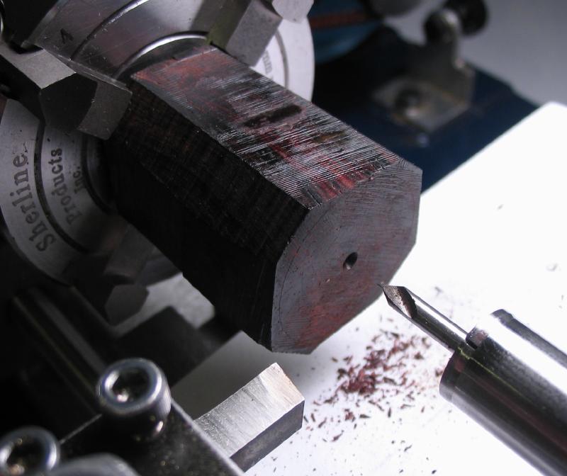
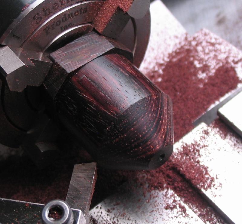
The handle was made from a roughly 1.5" length of about 30mm square cocobolo. I attempted to reduce the turning burden by sawing off the corners, however, this was likely more trouble than it was worth and the result was fairly mangled-looking piece of very beautiful wood. However, a center was located and punched, and that was then found with the tailstock while mounting the work in the 4-jaw chuck on the lathe.
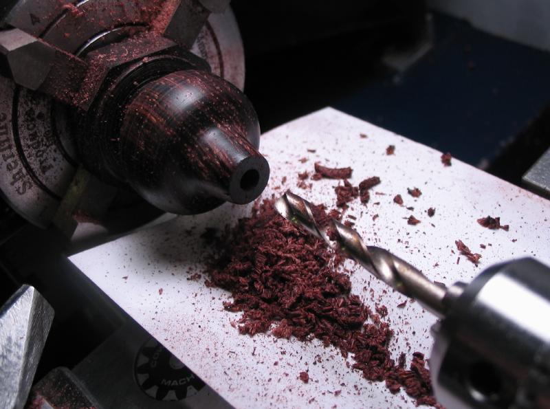
The center position was drilled for tailstock support and the stock turned round, which was still over 26mm in diameter, although a lot of swarf was produced. The end was turned with a taper of about 42 degrees to provide a start for hand turning below. A parting tool was used to establish the length.
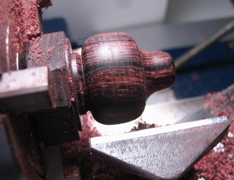
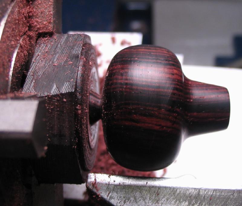
The final shape was slowly found by turning by hand with various round and square gravers. The handle was drilled through 4mm, and the surfaces smoothed with emery papers. It was parted off using a 3/32" square graver and the top face of the handle rounded over with the edge of the graver while progressing.
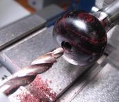
The top of the handle was countersunk with an M3 size cutter (6mm diameter seat) by mounting the handle on a 4mm rod held in the tailstock. The cutter was held in the headstock and the handle applied with hand pressure.
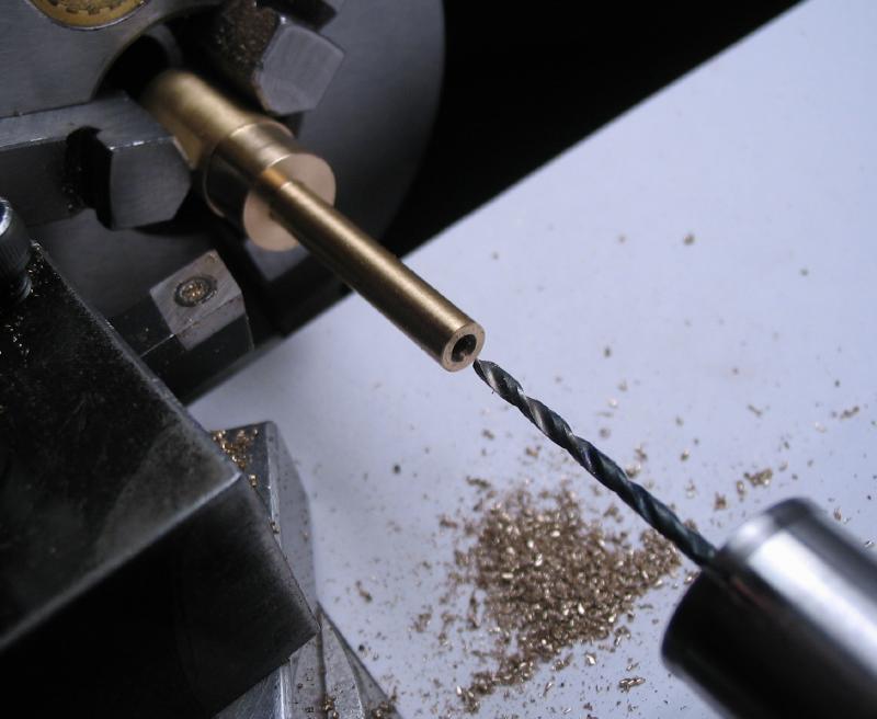
The handle post was made from 3/8" brass rod. The rod was turned to match the diameter of small end of the handle and to a length that is a couple millimeters short of the handle's length and to a diameter to fit the handle's bore. It was drilled and tapped M2, and then parted off.
The other end of the post was turned with a taper of about 15 degrees and then drilled and tapped M2. A 1/4" circle was scribed to act as a guide while turning.
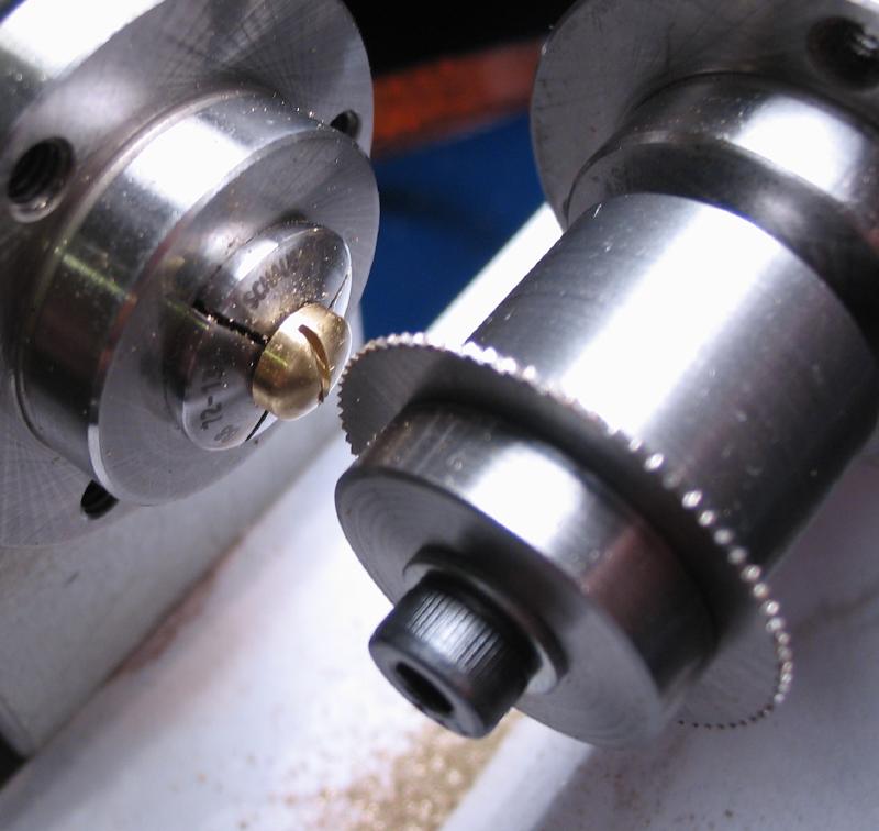
The screw was made from 1/4" brass rod, turned for the 6mm head diameter and for threading M2x0.4. After parting off, the reverse end was turned by hand to give it a rounded shape. A 0.020" width slot was cut with a slotting saw, and the finish improved with emery paper.
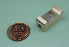
The 3/8" square bar was drilled for tapping #4-40, and a 2mm deep channel milled, centered on the hole and to match the width of the bracket, which is just under 5/8". The hole was then tapped and the various surfaces smoothed with files and emery paper,
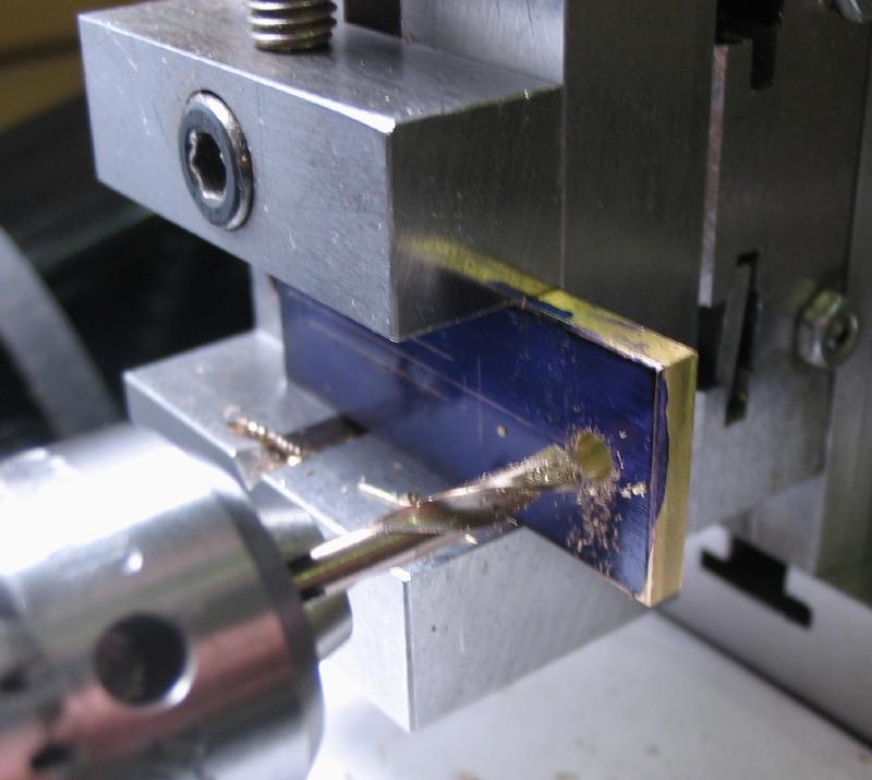
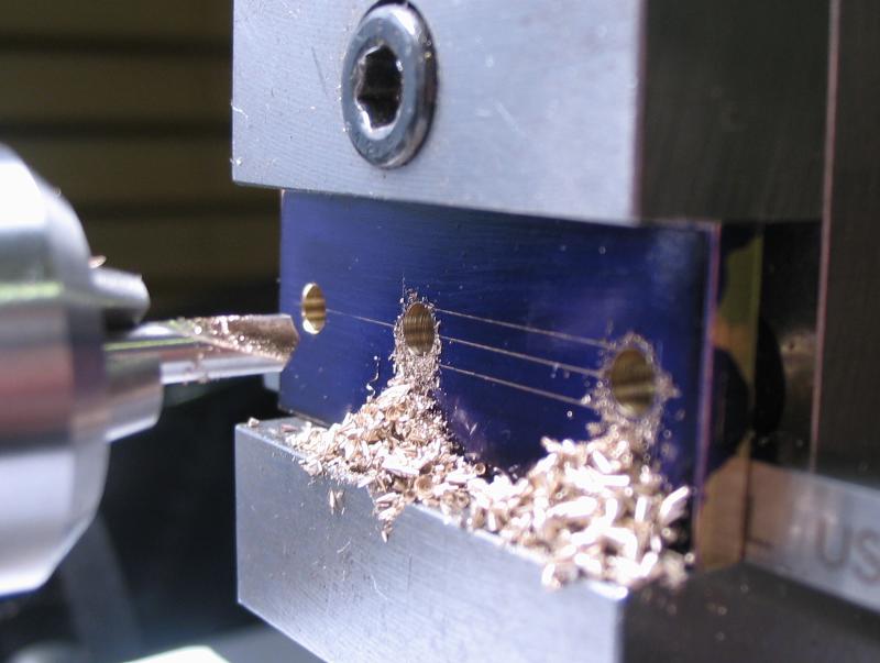
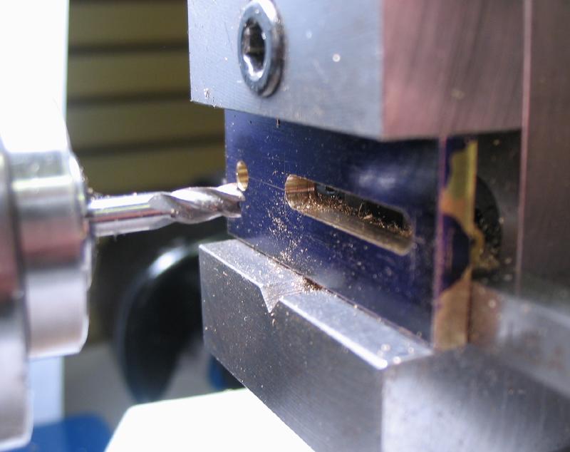
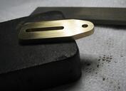
The roller bracket was made from 5/8" x 1/8" brass bar. A #32 hole was drilled to pass the threads on the roller arbor (below), and 1/8" holes drilled at the extremes of a slot that was subsequently milled with a 1/8" endmill.
After a check of the fit, the bracket plate was sawed and filed to its final shape.
The wheel was started from a short length of 5/8" brass rod. It was faced and chamfered on both sides, drilled through and reamed 3/16", and the hole openings countersunk.
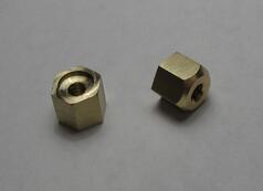
The diameter of the wheel will be radiused, but an arbor needed to be made first. The arbor will also be used on the finished tool. It was turned from 5/16" steel rod (12L14); a step was turned that is about 0.1mm longer than the width of the wheel and to a diameter that is a slip fit to the reamed hole of the wheel. The remainder was turned and threaded #4-40. Two nuts were made from 1/4" brass hex rod, one being counterbored to clear the 3/16" portion of the arbor and allow the wheel to be tightened and the other nut was made with a little more care and will be used on the finished tool.
The wheel was installed and turned by hand to round it over, and then smoothed with emery paper. This was intended to be a radius of 5/16", however, this was only approximated (the author of the construction article started with a 5/8" diameter brass ball).
The arbor was then parted off and mounted in a collet to turn the reverse end. This completes the components of the rear assembly.
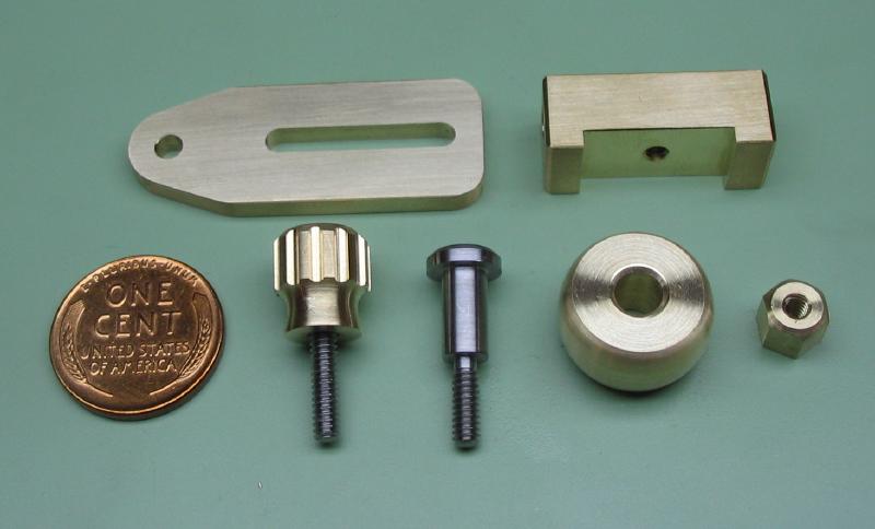
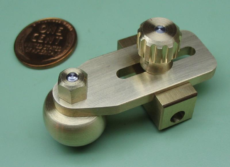
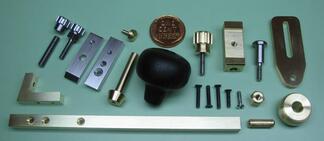
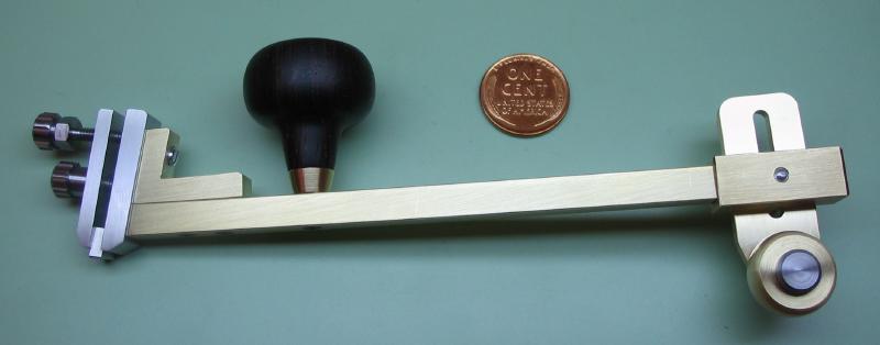
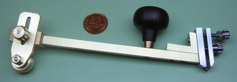
A photo of the all the parts was taken prior to attaching the square bar and the bracket guide. They were assembled with the 5/32" brass pin and a couple drops of Loctite. Photos of the assembled jig are shown as well.
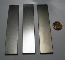
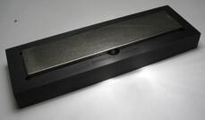
Three grades of diamond stone are shown. They are pocket size (4" x 7/8") DMT Dia-Sharp stones in coarse, fine and extra-fine diamond grit, which are cited as 45, 25, and 9 micron.
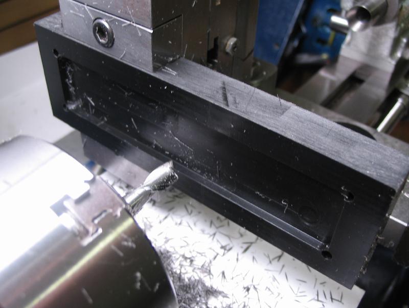
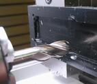
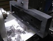
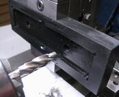
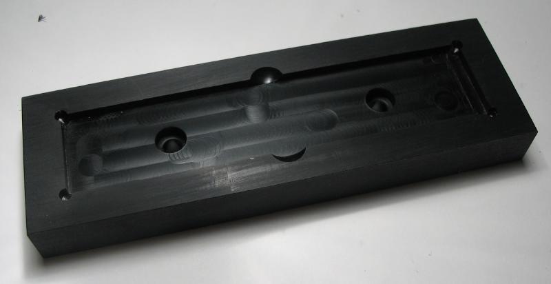
A holder for the stones was made from a 4.75" length of 1.5" x 0.5" Delrin bar. The sawed ends were squared by milling with a fly cutter and other surfaces were smoothed on emery paper at various stages of the process. A recess for the stones was milled with a 1/4" endmill, and I mistakenly drilled the corners 1/8" to provide relief for the corners of the stones. The excess material was removed with a 1/8" endmill - the result is not attractive, but the fit to the stones is very snug which is preferable. A couple finger notches for removing the stones were formed with a 3/8" ball end mill.
Two screw positions were drilled through 4.5mm and counterbored with a M4 bit.
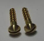
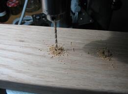
The stone holder will be attached to the base with two brass wood screws. They are slightly too large in diameter, so they were turned and given a polish as well. The base was made from a 11" or so length of 4"x1" oak board that was simply pilot drilled for the 2 screws, the corners rounded over, and surfaces sanded fairly smooth. Wood is less than ideal, since a flat and durable surface is preferred, however, the oak was on hand and after staining, it was given about 15-20 coats (I lost count) of polyurethane with 400 grit sanding in between until the grain of the wood was filled in, leaving a glassy smooth surface.
The complete tool is shown setup in the way it is used to sharpen an insert. A block of steel was used to prop the jig up for the photo, but is not otherwise used with the tool. It is not easy to mount the insert exactly square in the clamp, however the radiused roller allows the jig to accomodate whatever angle the insert is mounted (within some range of course), the height of the roller is adjusted to align the insert to the stone, however, in my early experiments the tool was tilted slightly towards the cutting edge. The result of grinding a face on the diamond stone is shown. The tip can be easily radiused by mounting the insert with tip pointing down and the radius of roller used to rock the jig during the stroke.
