Caseback
The back of the case consists of a bezel and an insert made from flat sheet stock. This insert is formed to a slightly domed shape for appearance and to accommodate any movement components that extend beyond the bezel height. The sheet is formed to its domed shape using a specially made forming tool. Daniels depicts such a tool in "Watchmaking" in figures 686 and 687 that consists of upper and lower shaped dies and a means of aligning them. A similar tool will be made below, with a notable difference; Daniels' version incorporates both the alignment base and lower die into one piece with a separate upper die. I am planning to make an universal base with alignment pins and make both the upper and lower dies separately. This adds another component, however, different lower dies can be more easily made and exchanged if need be. A more practical reason for the change is that the dies will have curved surfaces that need to be turned by hand and the size of the base is simply too large for my Cowells.
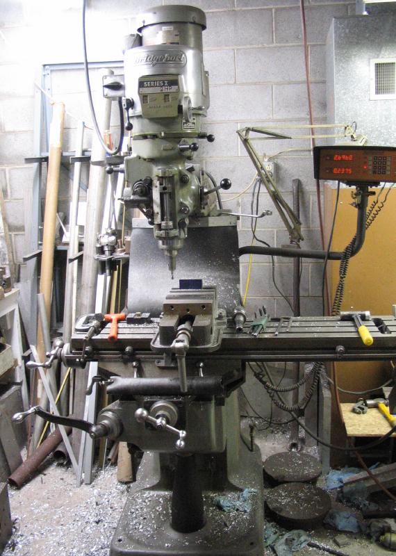
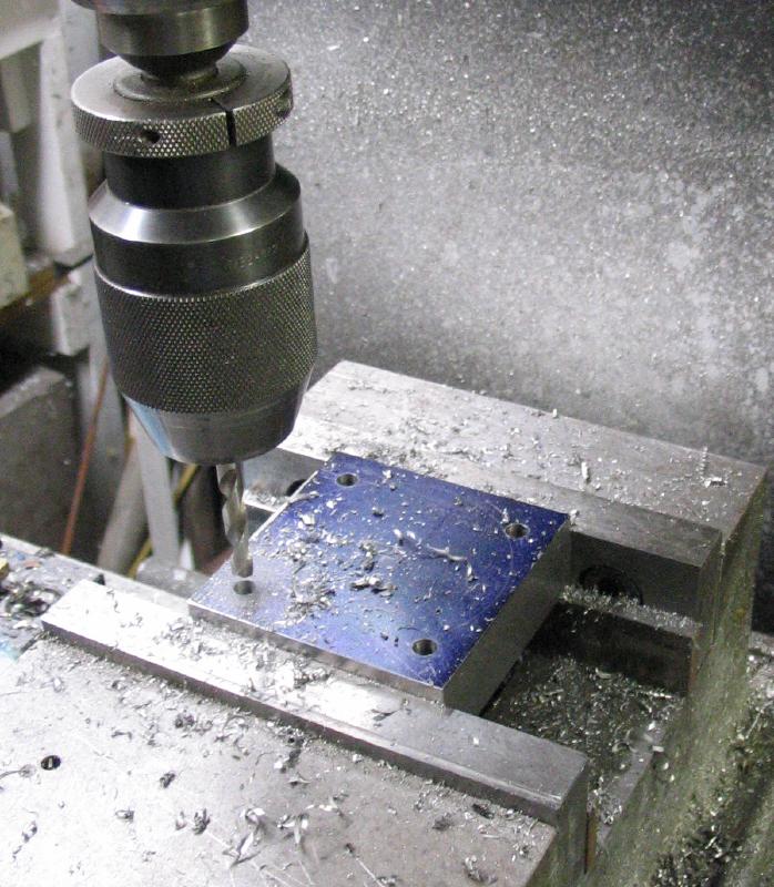
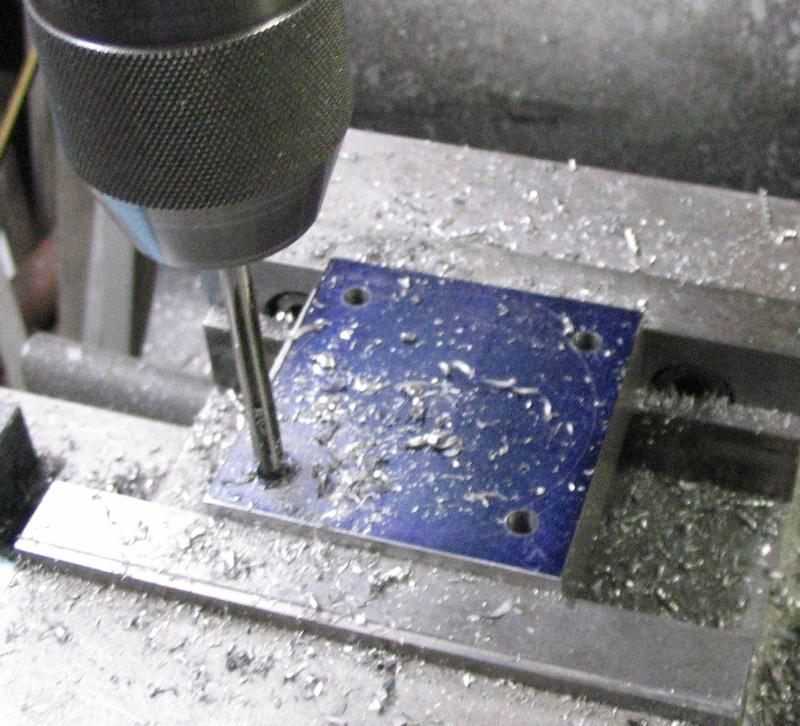
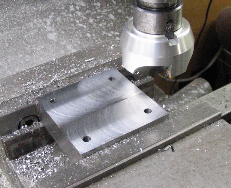
The base of the caseback former was started on a Bridgeport milling machine, shown below. The base is made from a 3 inch length of 1x3" rectangular steel (type 1018) bar. A 3 inch block was sawed off and then scribed with a 1.5" radius circle and four diametric positions center-punched on this circle. The dies will be 2-3/4" in diameter, so a circle was scribed on the block for reference and should be tangential to the alignment pin holes. The steel block is mounted on the cross slide of the milling machine in a vise with parallels beneath the block to bring the top surface just above the vise jaws. The center-punched positions were found, center drilled, and then drilled and reamed 1/4" to a depth of about 3/4". All the surfaces of the block were then milled flat using a shell-type endmill. Not shown, but the holes were then countersunk to remove burs.
|
|
|
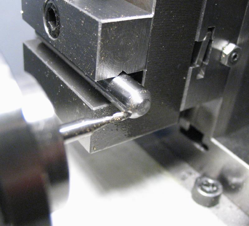
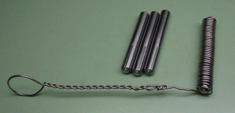
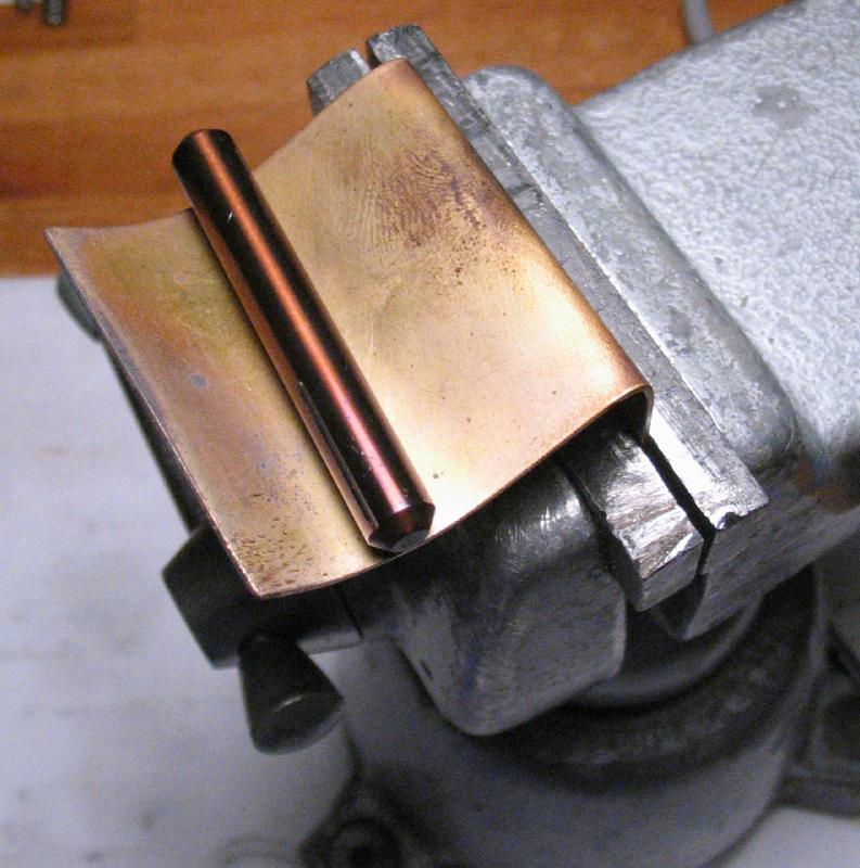
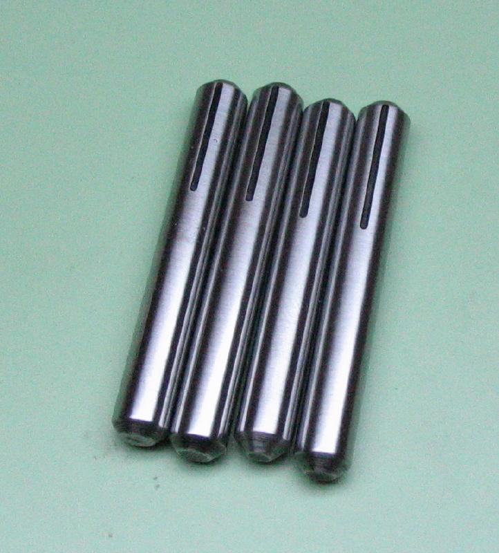
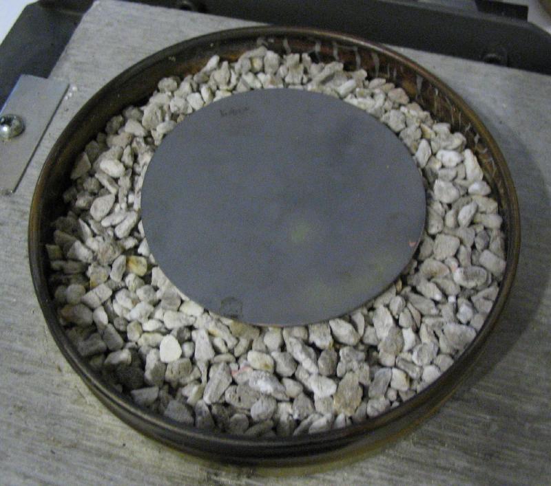
Alignment pins were made from 1/4" oil hardening drill rod. The ends were chamfered on the lathe and the surface smoothed with 800 grit emery paper. The fit is very snug in the base and since the holes are blind, a shallow groove was milled along the edge of each pin for about 16mm with a 1/16" ball endmill, The groove will allow air to escape when driving the pin into place. The pins were hardened in oil and tempered to an almost-turning-purple color. The exact temper did not seem critical, but should be hard but not brittle and elastic enough to resist deformation while tapping them into place or when using the finished tool. A basket was made from stainless steel wire to hold the pins during heat treatment. They were tempered on a piece of brass held in the vise. The pins were finally re-polished with 800 grit emery paper.
|
|
|
|
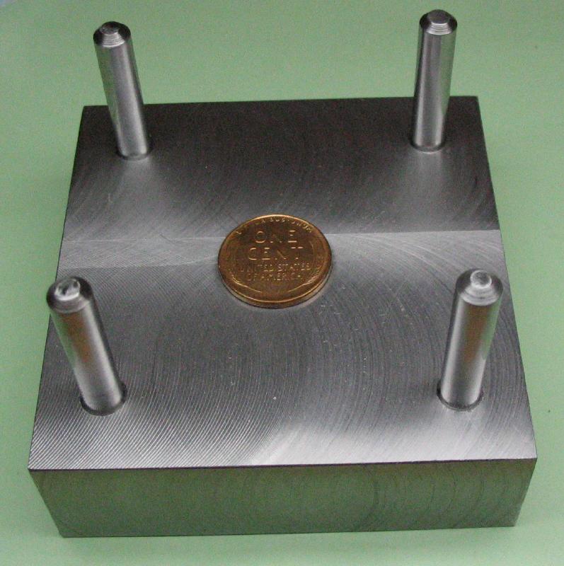
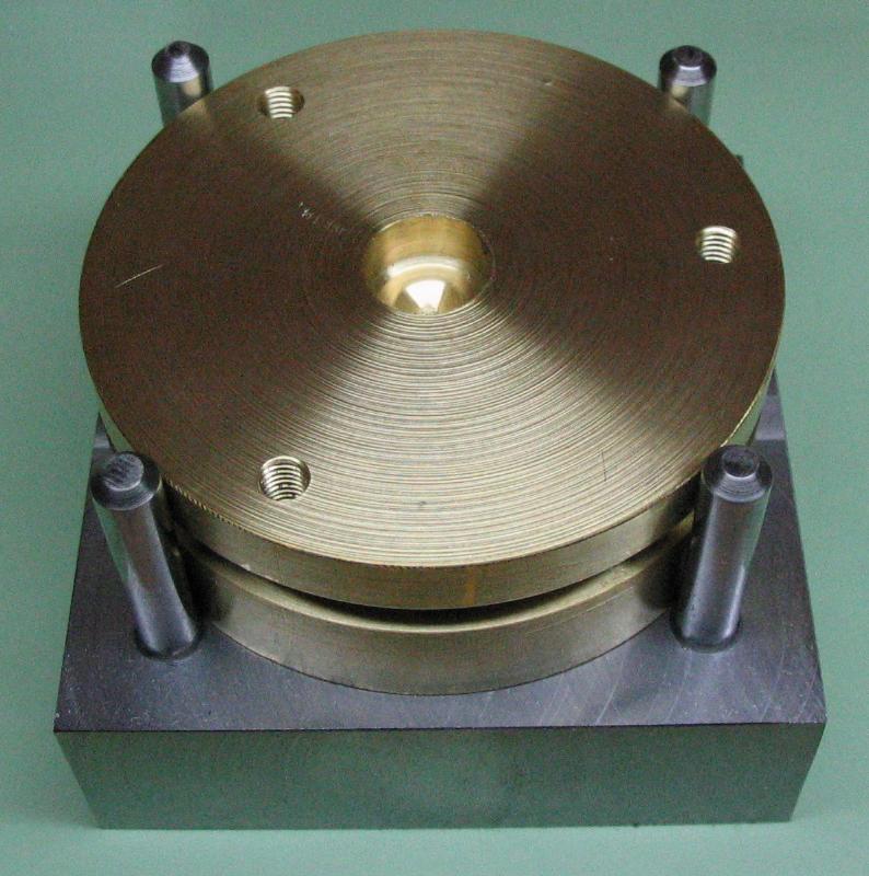
The pins were given a light coat of oil and driven into the base block with a small hammer.
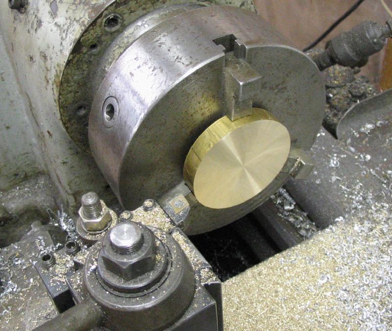
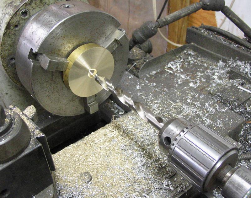
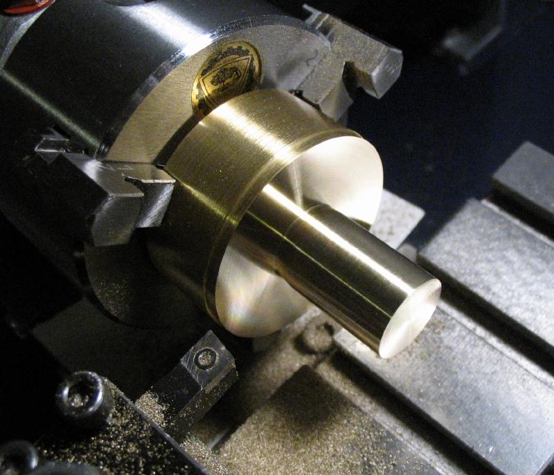
The upper and lower forming dies were started from 1/2" lengths of 2-3/4" brass (type 360) rod. They were faced on either side using a Monarch 10EE lathe, which easily holds and turns such a relatively large piece of brass. The upper die was drilled 12.5mm to about half-way through, and then reamed 1/2". This hole is to fit the driving ram made for the bezel forming tool.
|
|

|
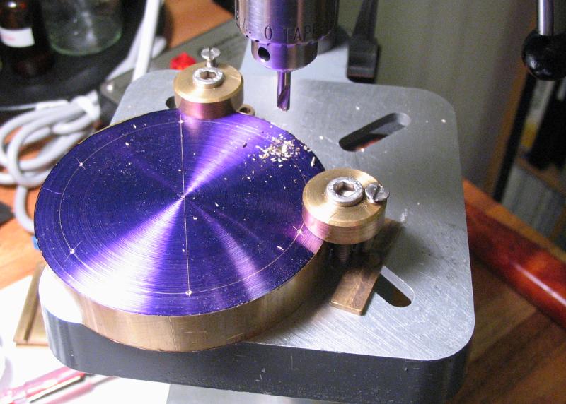
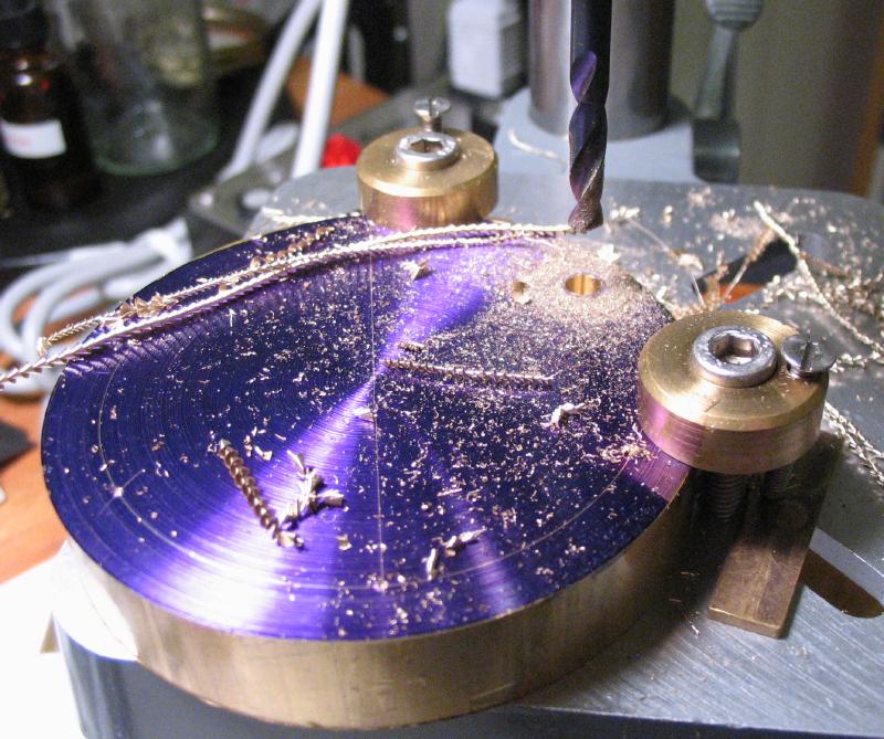
The discs will be turned to their final shape on the Cowells lathe, however, due to their size they will need to be attached to the faceplate. The Cowells faceplate has six slots for attaching work. Positions for fixing the discs to the face plate were laid out on each of the discs. I'll describe the method for laying out the points of a hexagon (I had to look it up myself). The back of the brass disc is coated in layout blue and the center found and then center punched. A center line is scribed through the center and across the face of the disc. From the center, a circle of 29mm radius was scribed using a divider - this dimension is not critical but must be maintained for the next step. The intersection of the center line and circle are center punched and the divider is again used to scribe the 29mm radius from each of the center line intersections. This will give a total of six, equally spaced intersection points on the circle.
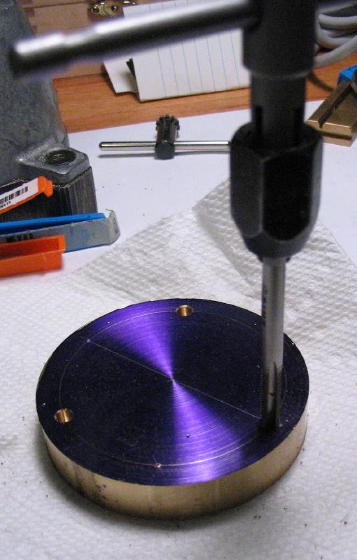
Three of the positions were center punched, if not already, and drilled 4.2mm for a depth of about 8mm. These holes were then tapped M5x0.8 using a plug tap followed with a bottoming tap.
|
|
|
The brass discs are attached to the faceplate using M5 (18mm length) socket head screws that fit through the faceplate slots. Brass washers were made from 1/2" rod. The rod is faced and drilled to pass the M5 screws and then washers parted off. The rod was turned down to 12.2mm prior to parting off the washers. The rod was faced and the hole lightly countersunk prior to parting off the next washer. The reverse sides of the parted washers need to be faced to make them flat. A Levin step collet with a 12.2mm step was used to hold them.
|
|
|

|

|
|
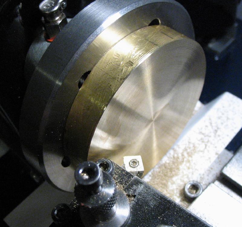
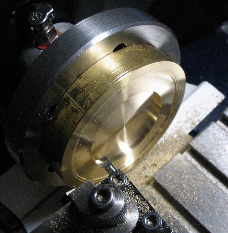
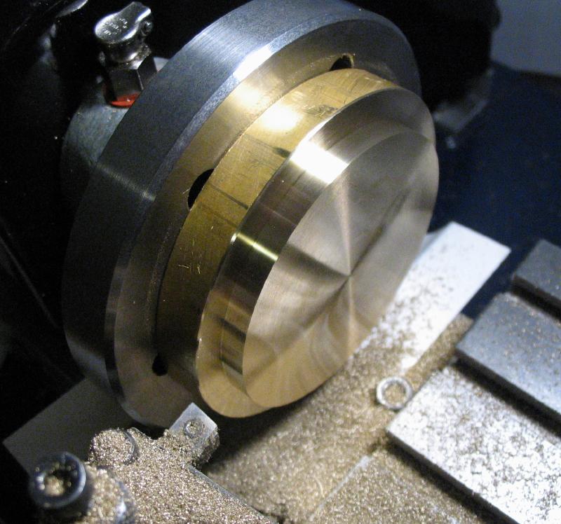
The lower die was started first. After mounting the faceplate on the lathe, the brass disc is brought on center. The outer diameter of the discs was not turned true, but was used to sight the disc onto center fairly well. The disc was first faced, and a clearance diameter of about 60mm was bored to a depth of about 0.5mm. A bore to the full diameter (58mm) of the caseback was made to a short depth and then a bore of about 40mm in diameter and to full depth (about 2.7mm) was made. These dimensions must then be joined together with a radius turned using hand gravers (primarily a round one made from 1/8" drill rod).
|
|
|
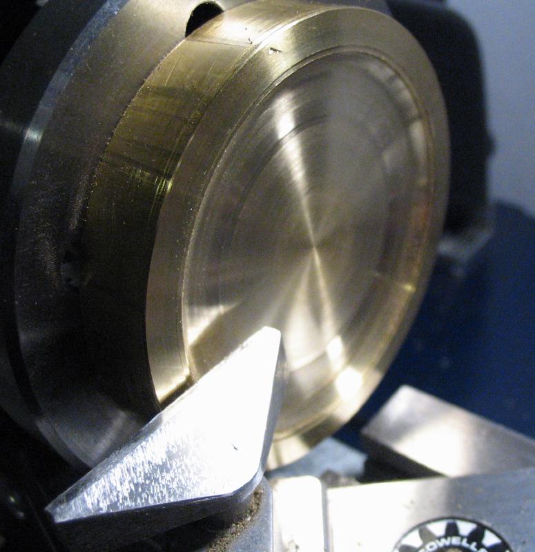
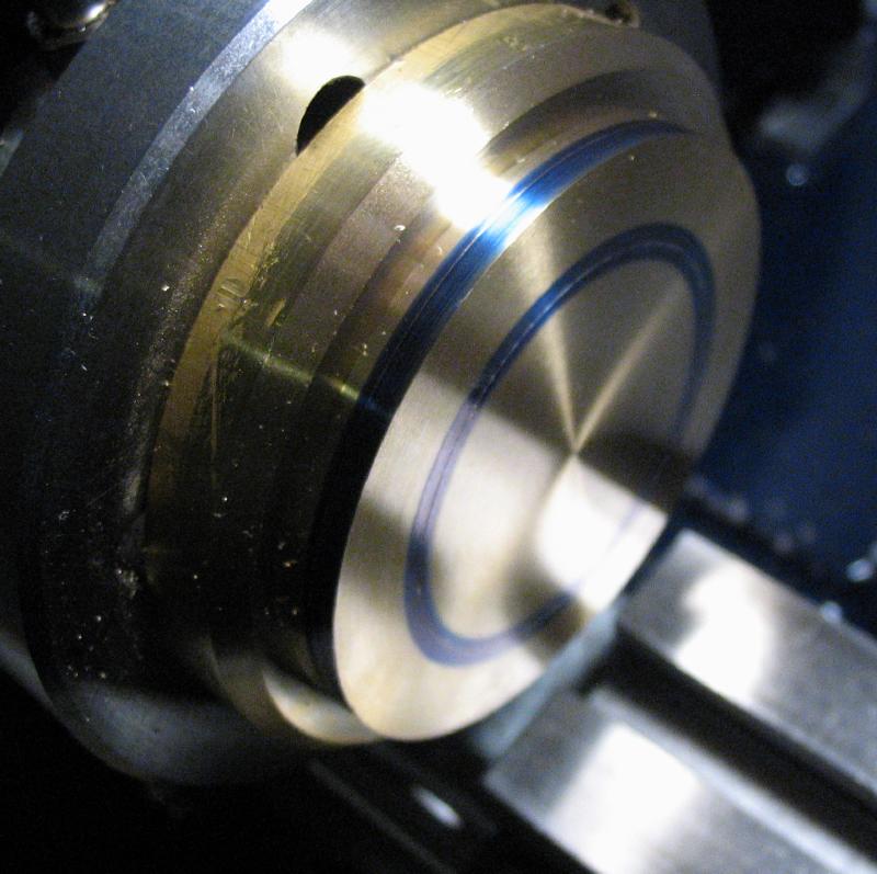
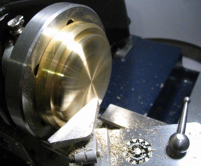
The upper die is mounted on the faceplate in the same manner as the lower die above and then faced true. A diameter of 58mm was turned for a surplus length of about 4.7mm. A divider and jenny-leg divider were used to mark out a diameter of 40mm on the face and a length of about 2.5mm. These will be the boundaries within which to turn a radius using a hand graver. Daniels recommends giving the upper die a curvature which is greater in radius than that of the lower die. The working surfaces of both dies were given a fine polish since a coarse finish will likely be imparted to the work.
|
|
|
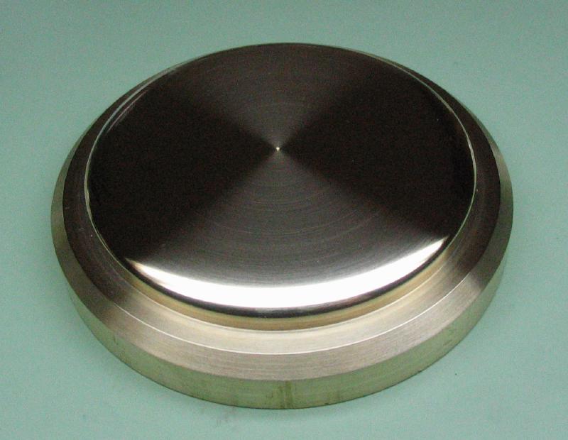
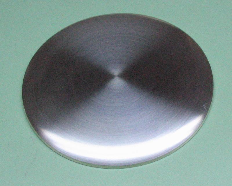
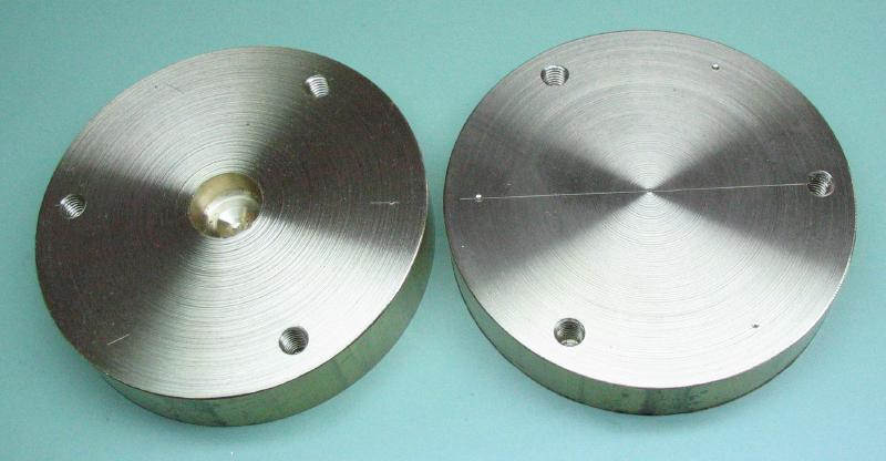
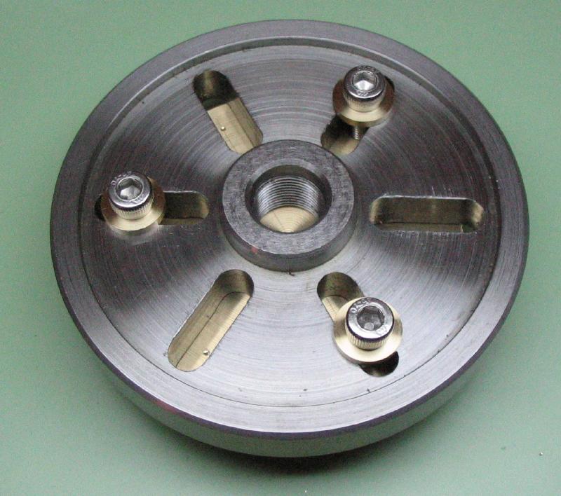
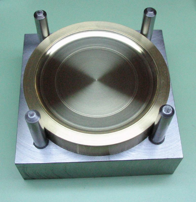
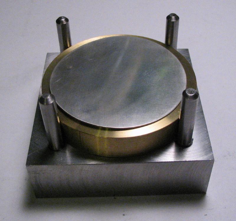
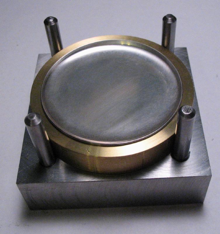
The completed components of the caseback former, ready for experimenting.
|
|
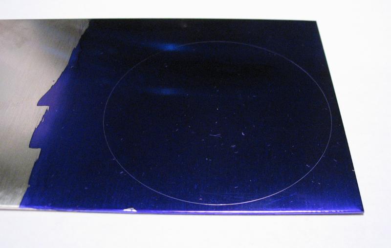
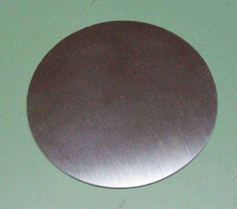
The caseback is made from 21 gauge (0.71mm) sterling silver sheet. The sheet was coated in layout blue and a circle was scribed about 60mm in diameter, avoiding the edge of the sheet since it is slightly rolled-over from the shearing process used by the supplier. The disc was then sawed out using a jeweler's piercing saw.
|
|
The sheet was purchased in the "dead soft" condition. However, as Daniels suggests, the disc was annealed prior to subjecting it to the forming tool to remove any stresses in the silver that may be present from the rolling process used in it's manufacture. Dead soft sheet could possibly be used as is, but it is a simple matter to anneal it. The temperature of the disc was raised to a glowing red color and after cooling briefly, plunged into water. Heating with a torch leaves the silver discolored and somewhat warped out-of-flat. It was cleaned up with 600 grit polishing paper and left in this relatively coarse finish since it will assist in forming a good bond on the cement chuck. The out-of-flat condition was not significant enough to be an issue, and any attempt to flatten it may work-harden it and defeat the purpose of annealing it in the first place...
|
|
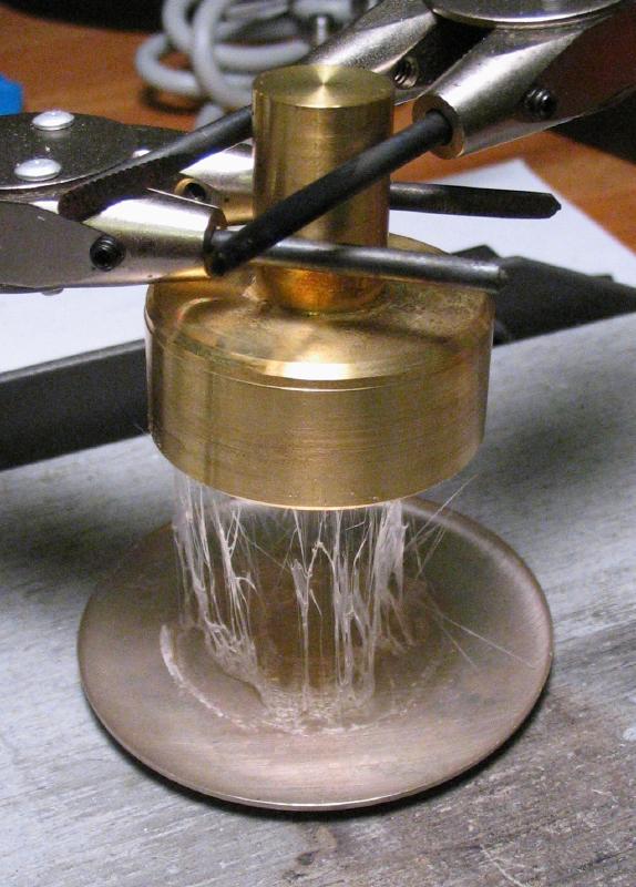
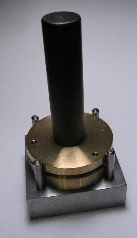
The disc was placed into the lower die and roughly centered. The upper die was carefully lowered onto the disc and driven in with one swift blow of a 40 ounce hammer (using the delrin ram, of course).
|
|
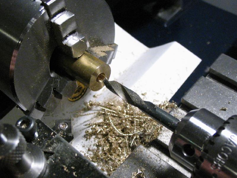
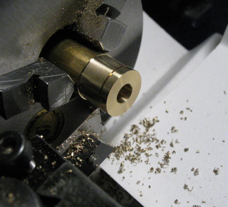
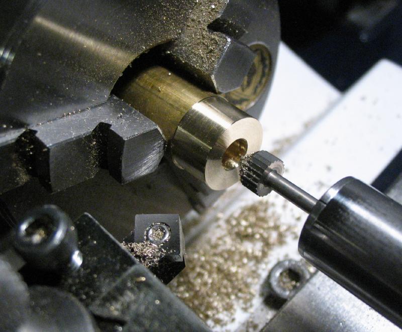
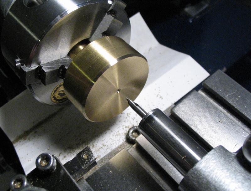
The formed caseback needs to be turned on the lathe to form the snap-fitting edge. It is held on the lathe using a cement chuck. To provide a means of centering the work after mounting, a special cement chuck arbor was made that can be held in the independent 4-jaw chuck. It was made from 1-1/2" brass rod, with a length turned down to fit within the center bore of the 4-jaw chuck with some freedom of movement available. The dimensions of the arbor were turned while held in the 3-jaw chuck. The diameters and face were turned true, chamfered, and center drilled for reference when locating the arbor in the 4-jaw to be roughly on center to start, Grooves were turned into the face to provide a space for the adhesive.
|
|

|
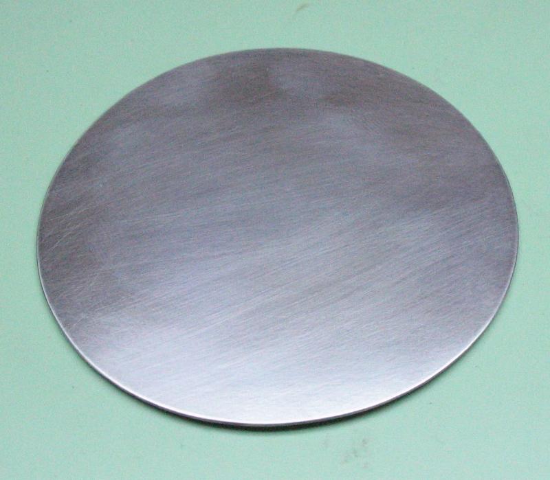
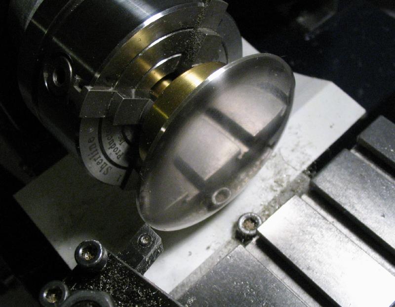
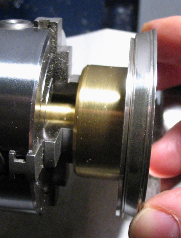
The caseback was adhered to the cement chuck with superglue and the edge turned with a 10 degree taper. The back bezel can be offered up, and although difficult to see (especially in the photo) the correct fit is when the smaller diameters of each taper match up. The back was given a better polish at this stage while mounted on the lathe.
|
|
The caseback was removed from the cement chuck using a torch, heating the chuck itself until the glue melts and the work can be separated. The residue can be easily scratched off and the last remnants removed with acetone.