Winding Barrel
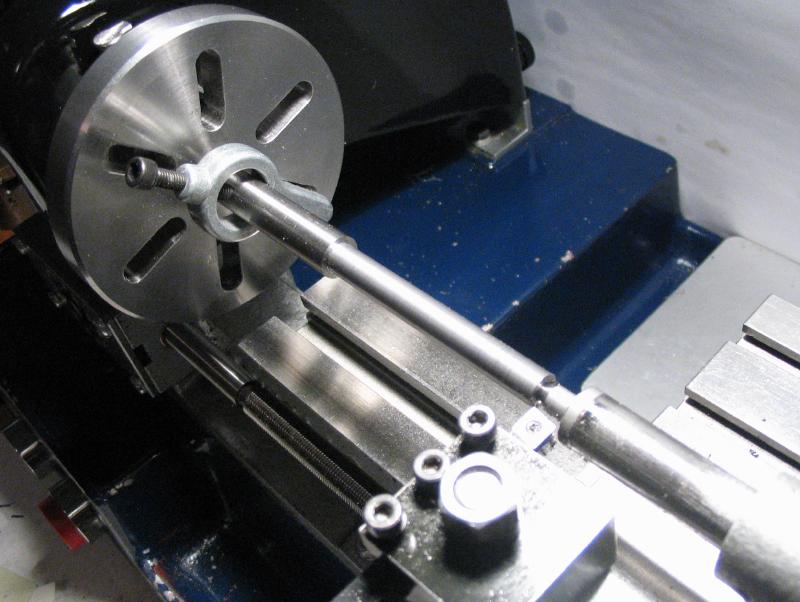
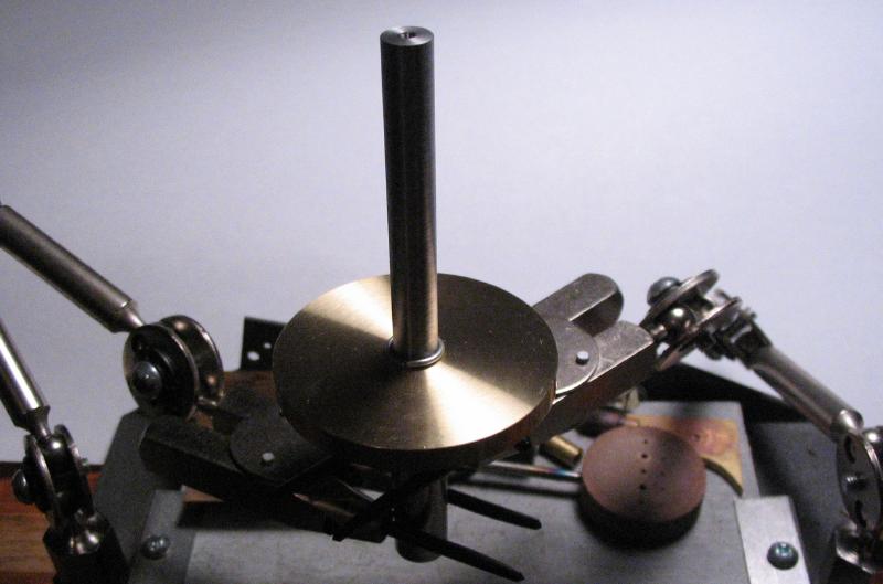
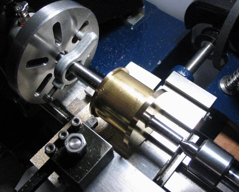
The winding barrel is the first part of the clock described and is started with the arbor, which is made from a length of drill rod. The rod was mounted in the 3-jaw chuck and supported in the fixed steady rest to face and center-drill each end of the rod. The rod can then be mounted between centers for turning. A Sherline bent-leg drive dog was attached to the rod and it was mounted between centers on the lathe. The faceplate was used to drive the work. The rod was turned down to form a long shoulder where the barrel components will mount. The diameter of the shoulder was checked at various points while turning down to the required diameter in order to ensure that a uniform diameter is being formed. If the headstock and tailstock centers are not in alignment a taper will result. If a small taper exists, it is to be preferred that the smaller diameter is on the tailstock end. After a minor adjustment to the tailstock offset, a taper of about 0.1mm over its length was found in the finished work.
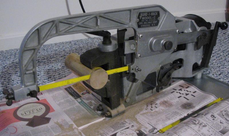
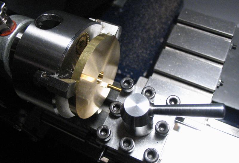
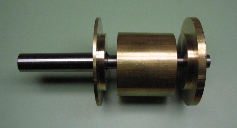
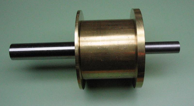
The barrel itself is fabricated from three sections of brass stock, including two flanges that are made from round rod and a center portion made from brass tube. The first flange was sawed off using the Hand-i-Hack and then mounted in the 3-jaw chuck to make a facing cut on either side. It is then drilled and bored open to fit the turned portion of the arbor made above.
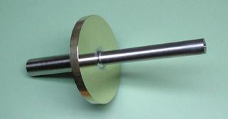
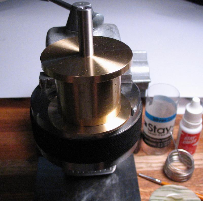
The flange can then be mounted onto the arbor and the two components are soldered together. I am using Stay-Bright solder (a tin-silver alloy); the joint is coated with the included "Stay-Bright" flux and a ring of solder wire is placed adjacent to the joint. I heated the work from below using a propane plumber's torch until the solder liquefies and flows into the joint. An excess was used and a good solid joint appears to have been made. The discoloration was cleaned off with some brass polish, and it is ready for the next step.
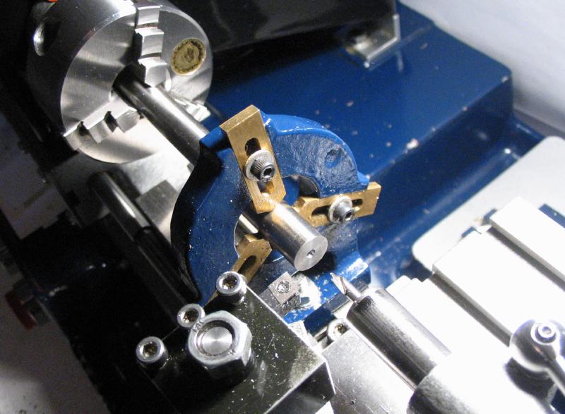
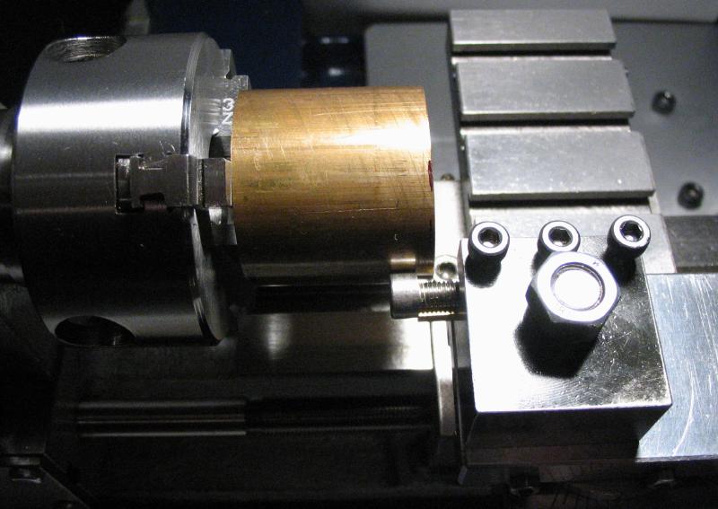
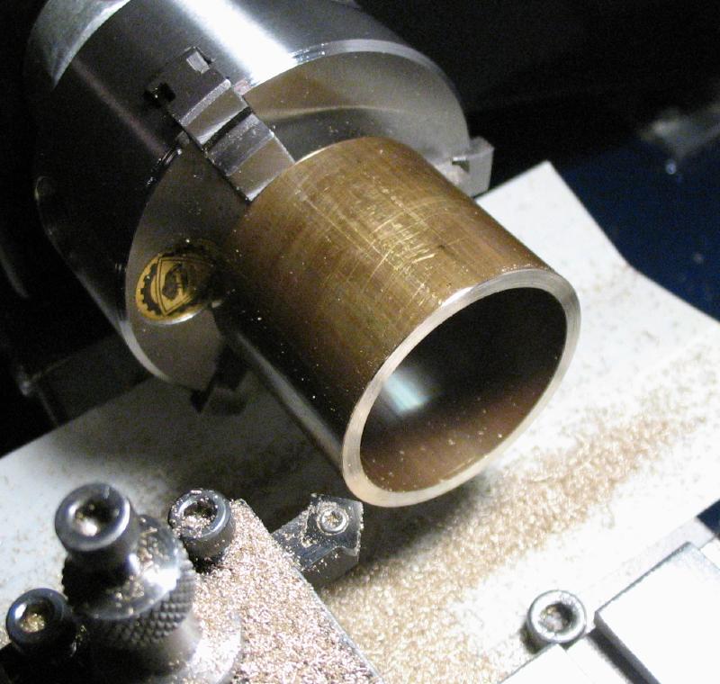
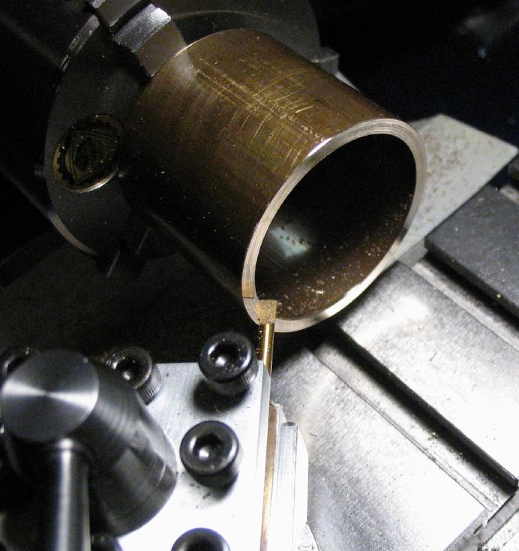
The middle section of the barrel is made from 1.5" diameter brass tubing (3/32" wall thickness). A piece of tubing with this wall thickness does not appear to be regularly stocked by metal suppliers, and I ultimately found a length of it on ebay. This happens to be type 377 brass, which is specified as a leaded, free-machining brass, and based on my limited exposure, appears to be very similar to type 360 in its machinabilty. A slightly oversized piece was sawed off and mounted on the 3-jaw chuck (gripped from the inside). The hacksawing leaves somewhat uneven ends, so it must be carefully mounted on the chuck and made to run true using the outer diameter. I used a socket head screw with a smooth head mounted in the toolpost to assist in truing the tube. The work can then be faced, and when reversed on the chuck it can be mounted more securely against the chuck jaws and then faced on the reverse side as well. The openings were counterbored slightly to remove burrs and provide a good fit later on.
The soldered flange and arbor was mounted back between centers and a step turned onto the flange to provide a snug fit with the barrel tube.
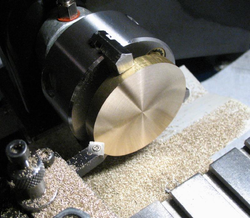
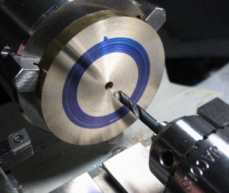
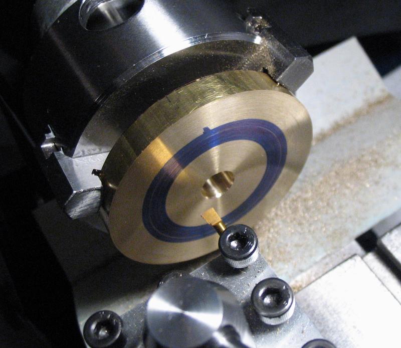
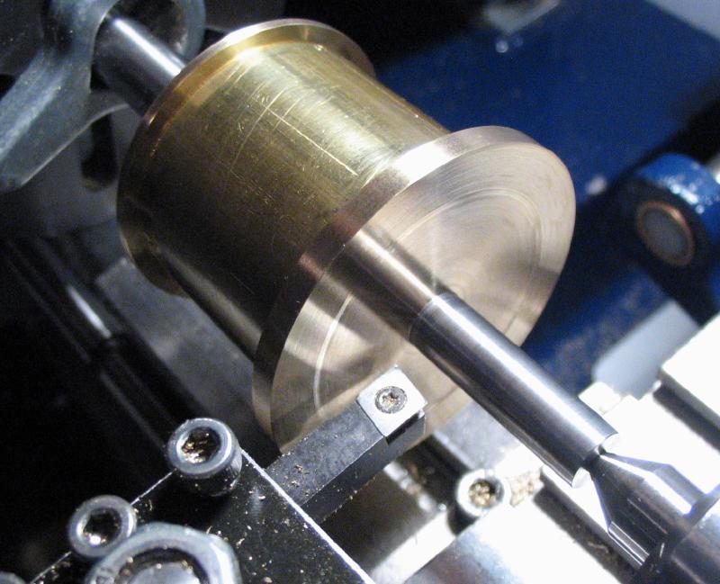
The second flange, which will become the ratchet later on, was started from 2" brass rod. Wilding specifies a thickness of 1/4", however, I suspect the jaws on my Bison chuck are a little deeper than the chuck he demonstrates this step with, so a slightly thicker piece was needed to allow a sufficiently long step/boss to be turned. The disc was first faced on either side, and then drilled and bored open to fit the arbor. The layout was scribed on the face after spot drilling, that is, the drill center was used to pivot a divider to roughly lay out the diameter of the boss for fitting to the tube.
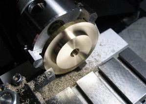
The flange was then turned down to form the step to fit the barrel tube.
The parts can now be assembled. The second flange is then soldered to the arbor as done with the first. Wilding recommends a heat sink to prevent the first solder joint coming undone. He uses a large block of steel with a hole to accept the arbor. Not having such a piece of steel laying about, I fixed the toolmakers bench block into the vise and inserted the assembled barrel into the closest fitting hole.
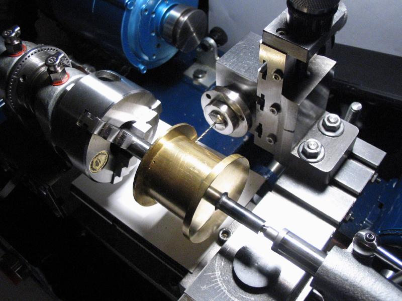
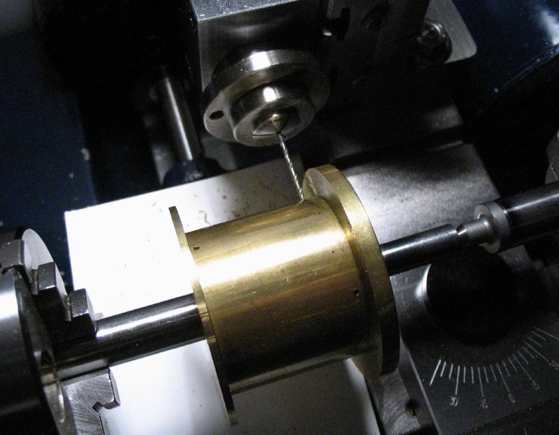
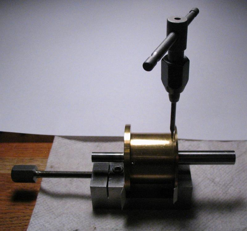
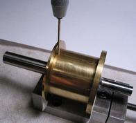
The brass components must now be pinned together. The assembled components are again mounted on the lathe, however, using the 3-jaw chuck with tailstock center support. The headstock is locked and can be indexed 120 degrees to allow three, equidistant positions to be drilled through the barrel tube and into the stepped portion of each flange using the milling spindle mounted on the vertical slide. The hole positions were staggered (60 degrees) between the two flanges, totaling six positions. The holes were countersunk and then tapped #0-80 UNF. Tapping was performed free-hand with the barrel held in the machine vise on the benchtop, less than ideal with a small tap since it's a recipe for breaking the tap off. However, all went well.
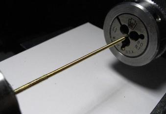
Some studding was prepared from 1/16" brass wire held on the lathe and threaded with a #0-80 die. Wilding uses 10BA, however, #0-80 can also be directly threaded onto 1/16" wire, so it was a convenient alternative.
The studding is held in a pin vise and screwed into the tapped holes in the barrel until snug. A pair of nippers were used to cut the studding off flush with the surface of the barrel. A needle file with a safe edge was used to remove any excess studding that was still protruding and give a reasonable smooth finish.
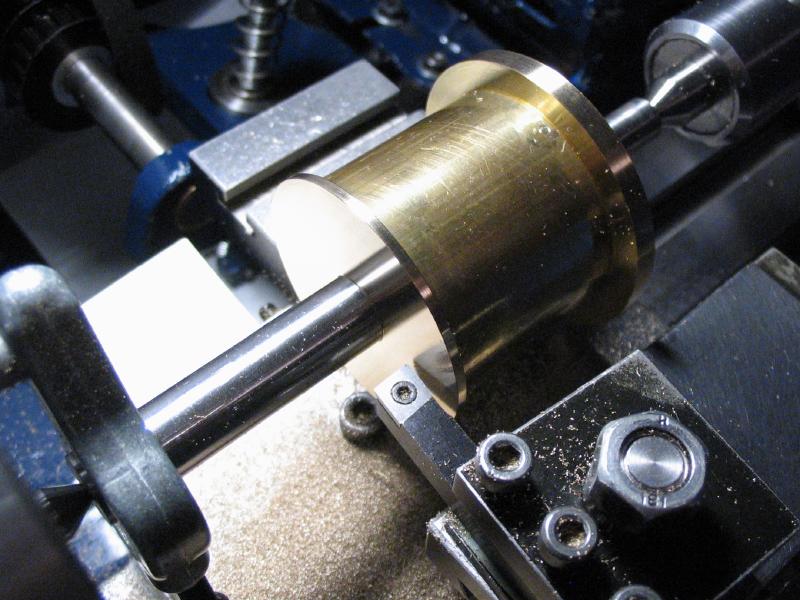
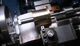
The assembled barrel can now be returned to the lathe, between centers, and the diameters of each flange reduced to their final specification. Once the ratchet flange was turned there was sufficient clearance for the cross slide to fit underneath and reach the cap flange. The faces of each were also turned to their final thicknesses and a slight recess was given to the ratchet flange since this face will contact a mating component. The solder joint on the ratchet flange is turned away during the process, and it can be observed whether solder flowed into the joint as the face is reduced away.
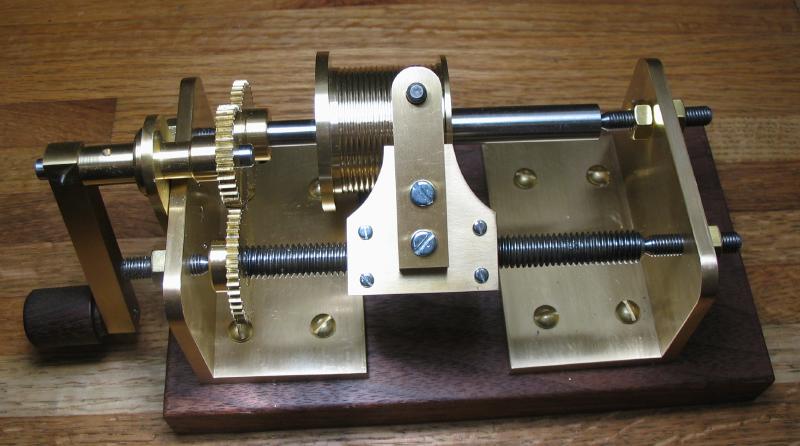
The outside diameter of the tubing portion was turned true using right and left-hand lathe tools. This was in preparation of forming the groove for the weight cable. A left-hand, 16 thread per inch groove is needed and not having screwcutting abilities on my lathe, an alternative method was needed. The grooving was carried out using Mr. Wilding's design for a fusee grooving device for those lacking a screwcutting lathe. The device and the grooving process is described on a separate page and the results shown below. I describe this step rather matter-of-factly, but the barrel has been patiently waiting in a drawer for a number of years while I decided how to carry out this step.
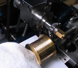
The ratchet teeth were milled with a 60 degree Thornton cutter.
