Graver Sharpening & Honing Jig
Sharpening gravers by hand is a skill requiring quite a bit of practice. The trouble lies in keeping the graver at exactly the same angle and flatness during each stroke against the bench stone. A common cheat used by many a watch and clockmaker is to use a sharpening jig. There are a number of commercially made jigs that can be purchased for such use. I thought it would be a fun project to make.
Plans for a graver honing jig can be found in John Wilding's "Tools for the clockmaker and repairer : how to make and use them." I made some modifications to his design as it is in Imperial dimensions, uses BA threads and is designed for use with 3/16" gravers. Aside from the dimensions, I will be following his methods and design. I made a drawing, however, once I started making it I ended up using various metal cut-offs (scrap) and may not follow the drawing exactly.
Plans for a graver honing jig can be found in John Wilding's "Tools for the clockmaker and repairer : how to make and use them." I made some modifications to his design as it is in Imperial dimensions, uses BA threads and is designed for use with 3/16" gravers. Aside from the dimensions, I will be following his methods and design. I made a drawing, however, once I started making it I ended up using various metal cut-offs (scrap) and may not follow the drawing exactly.
| Graver Honing Jig |
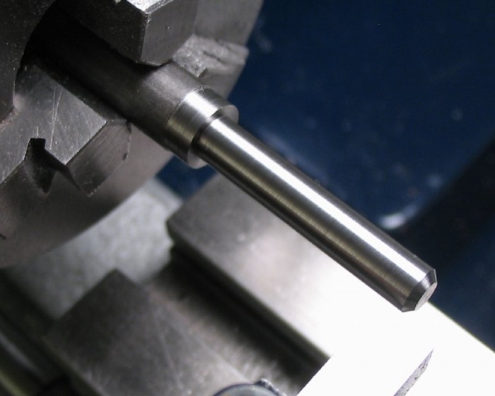
The roller pivot was started first. Made from 5/16" 12L14 cold drawn steel. As my first experience with 12L14 steel, I must say it is a pleasure to machine, it may even turn easier than 360 brass.
The roller was made next. It was made from 3/8" 12L14, drilled through with a 5mm drill and reamed 5mm+, and the end bored to accept the flange on the roller pivot.
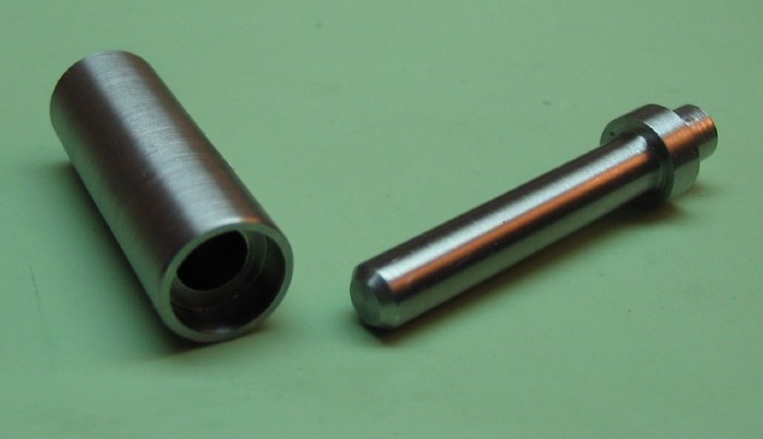

The pivot shaft was marked for the length of the roller, and cross drilled and broached to accept a taper pin. You can see some chatter marks on the beveling, had not noticed them until I looked at the photo...
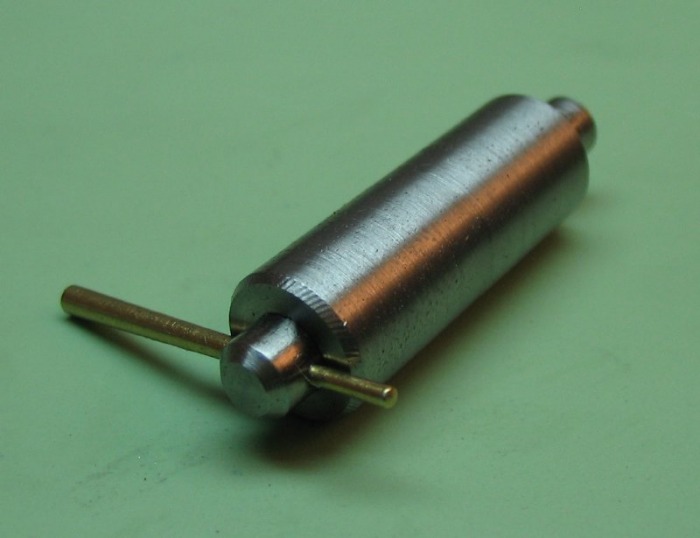
A connecting arm was sawn from 1/8" C1018 cold rolled steel bar. It was drilled to friction fit the 3/16" boss on the roller pivot shaft and 5mm to clear the threads on the clamp, made below. The setup shown in the photo, I was about to attempt some spot polishing on the surface of the arm, but was unsatisfied with the result and ultimately went back to a straight grain finish. Always worth the practice, learn a little with each try.
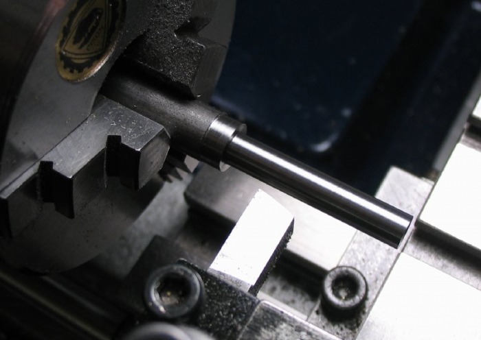
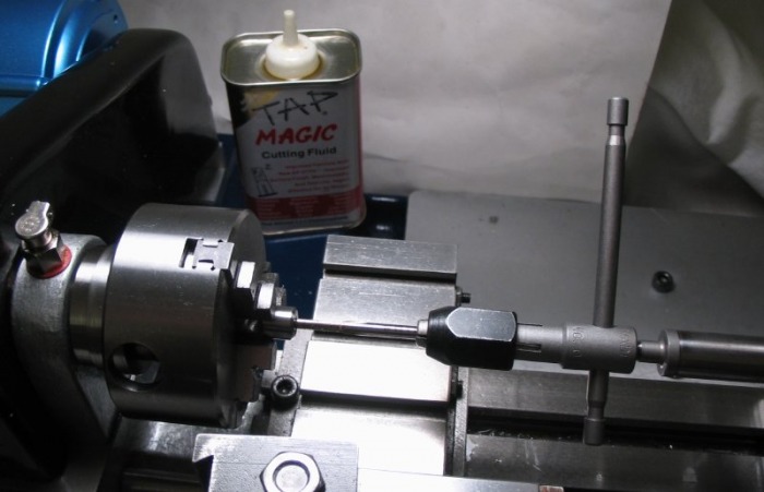
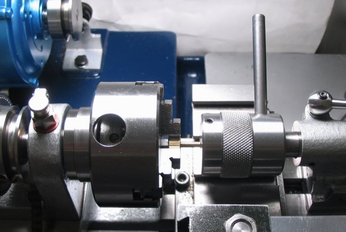
The clamp is made from the 3/8" 12L14 steel rod, a length of which was turned and threaded with a 5mm die. A photo of the test fitting of the clamp to the rest of the assembly is shown, a simple hex nut was used to secure it, perhaps a nicely made knurled thumb nut should be made... The rod is reversed and the other end center drilled and drilled 2.6mm for tapping with a 3mm tap. The tapping setup is shown using tailstock center support.

Center Drill
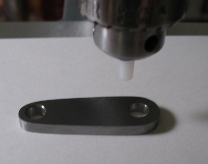
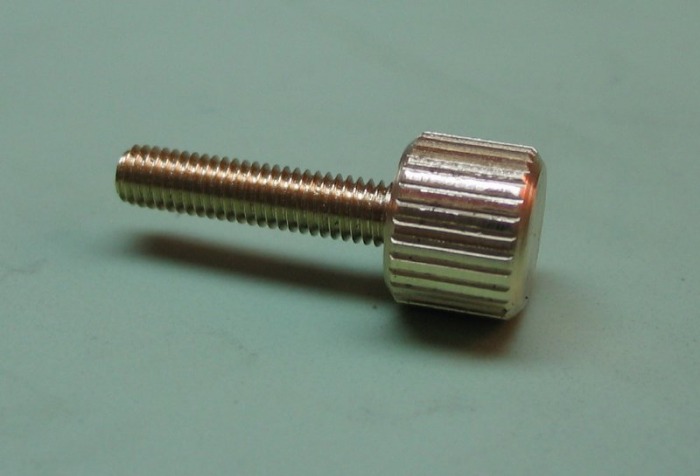
The thumb screw for the clamp was made from 5/16" brass (type 360). It was threaded for 3mm, a photo of the threading process is shown. The head was to be knurled with the new knurling tool purchased from Cowells, however, I was not having much luck with it. After some assistance on the Madmodder forum, the nominal diameter of the work for use with the Cowells knurling tool should be in increments of 1/8". This is based on circular pitch of the teeth on the tool; 65 teeth going around the circumference and a diameter of 0.625" gives a value (0.009615384615) which determines the diameters of work that will work. For example 1/2" is an integer multiple of this value (52). Marv Klotz's website has a program (KNURL) that assists with these calculations. Using that program, the 5/16" rod should have been turned down to 0.308".
Instead, I ran a threading tool (held sideways) into the side of the work, effectively engraving a groove, then indexed through 30 positions to give a pseudo-knurled pattern.

Threading with Tailstock Die Holder
Update: The brass thumb screw is much too soft for its intended use. I considered making another in steel, but resorted to using a standard M3 socket head screw. Cheap and easily replaced.
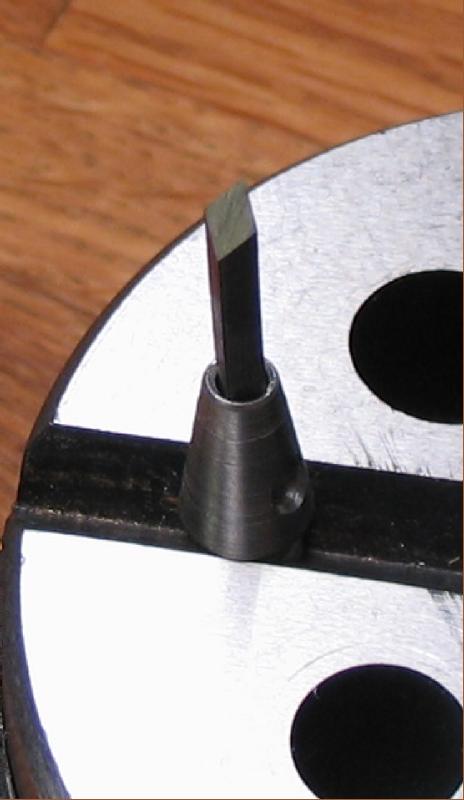
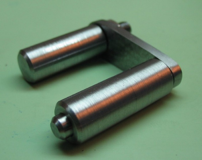
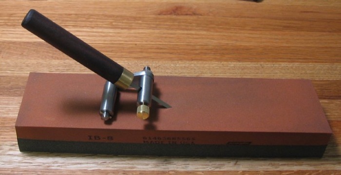
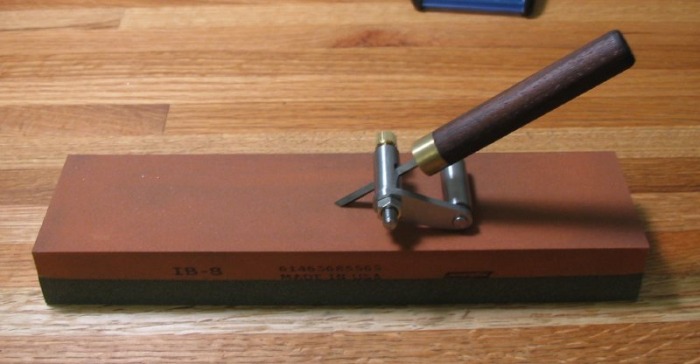
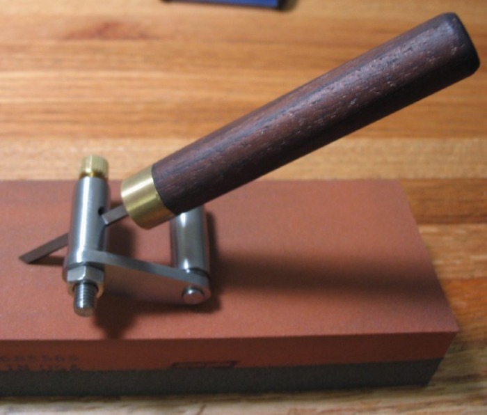
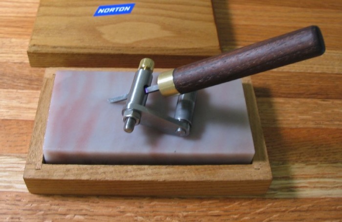
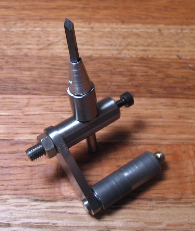
The clamp was then cross drilled on the Cameron with a 4.5mm drill (the approximate "diameter" of a 1/8" square tool bit). A square needle file was then used to form a pocket that the gravers can rest in (see photo below). This photo is the completed jig.
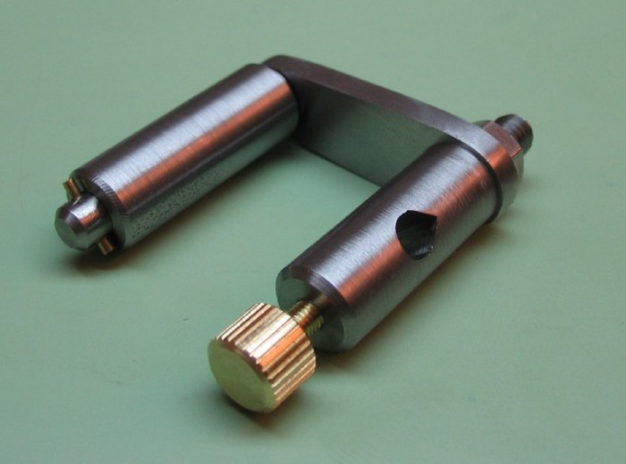
The jig is adjusted to match the angle of the graver, and one can then simply start grinding with relative ease compared to doing it freehand. I then spent the following evening devoted to graver sharpening ...
  |
  |
After grinding the face on the COARSE side of the Norton India stone.
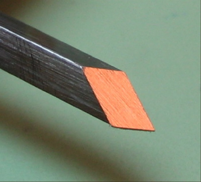
notice the rag build up on the edge
After grinding the face on the FINE side of the Norton India stone.

After grinding the face on the HARD ARKANSAS Norton stone.

Could use a few more strokes, I think...
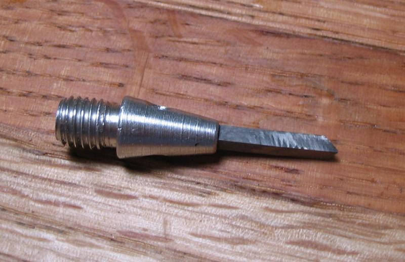
Carbide gravers (specifically the Waller brand of graver) are very useful, but easily chip at the cutting edge or point. This usually requires significant stock removal to present a fresh cutting edge. It is certainly not any easier to hold these gravers flat than the HSS gravers above.
The Waller gravers have a removable tip. This tip has a 1/4"-28 thread. A holder to fit the honing jig was made to also accept these threads.
 Badly chipped |
 |
The holder was started from 3/8 mild steel. Center drilled and turned using tailstock center support. As the work gets small, a small home-made half center was used.
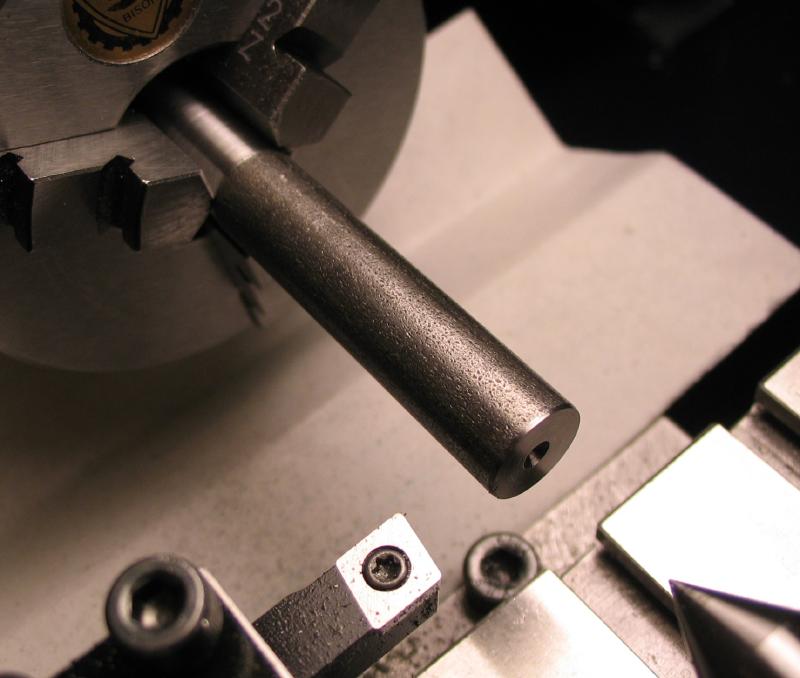
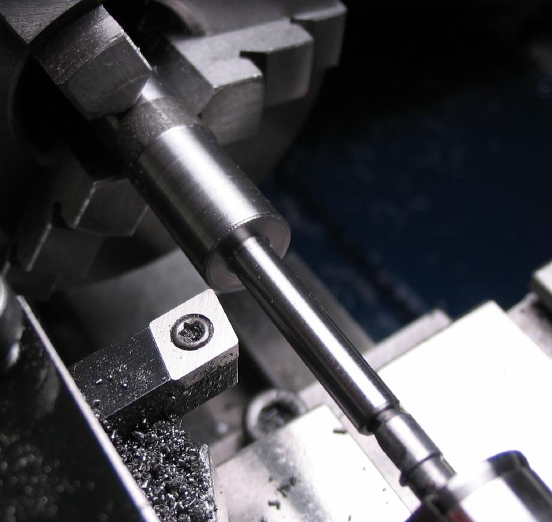
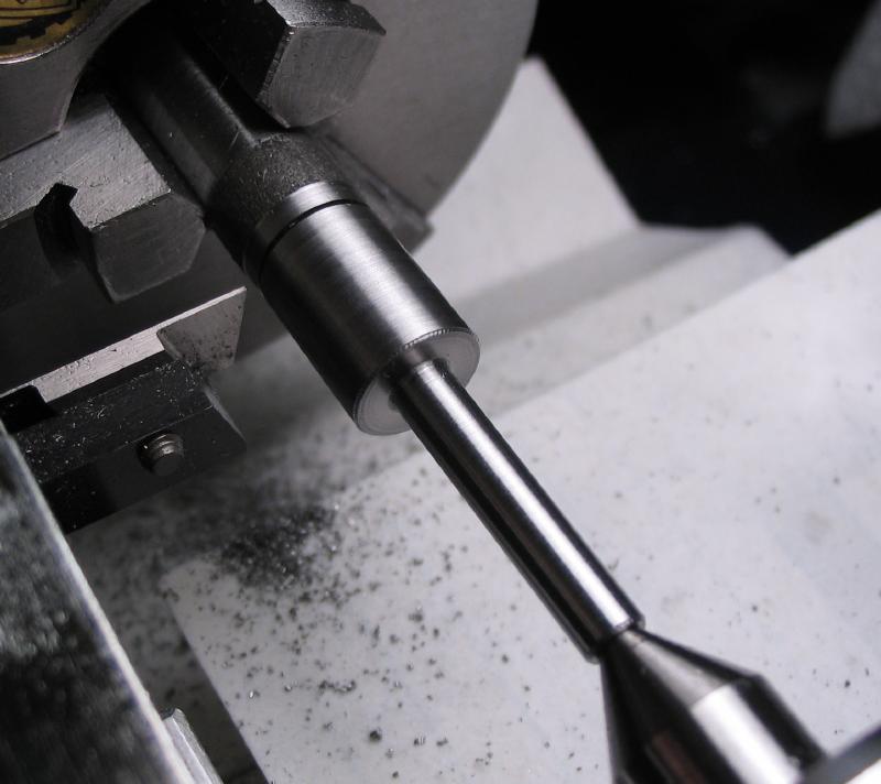
The work is reversed in the 3-jaw and drilled for tapping 1/4"-28 (#3 drill). A bottom tap is needed.
The graver tip is screwed in and the reduced diameter held in the honing jig. A DMT Dia-Sharp diamond stone is used for cutting carbide. For a badly chipped graver, start with the Extra-coarse and work down to Extra-fine after restoring the flat.
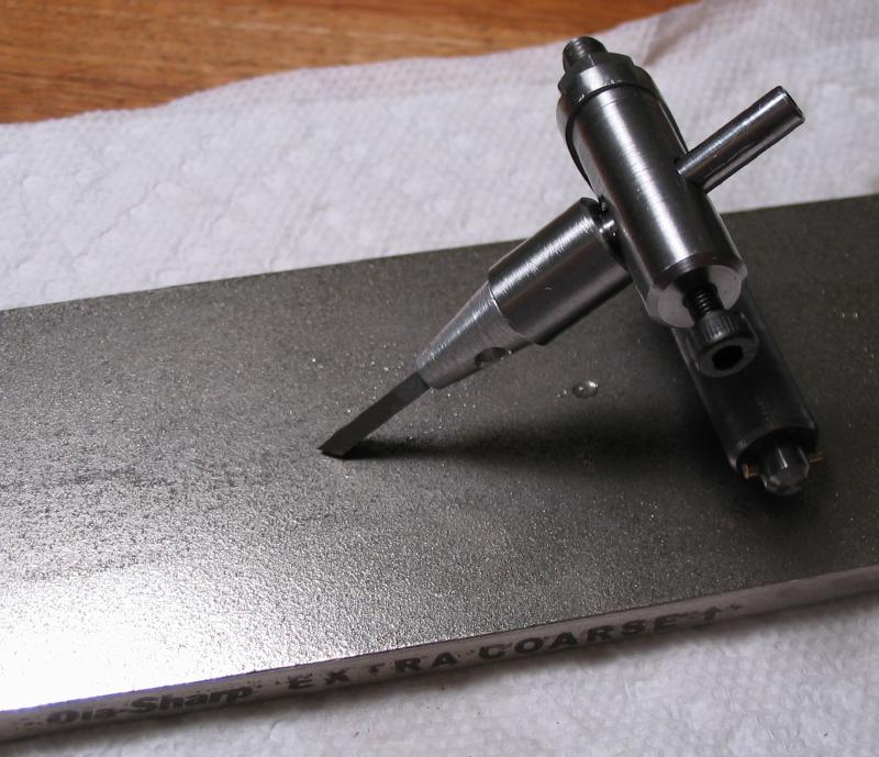
The chipped graver tip above was resharpened and is shown below (although a little blurry...)