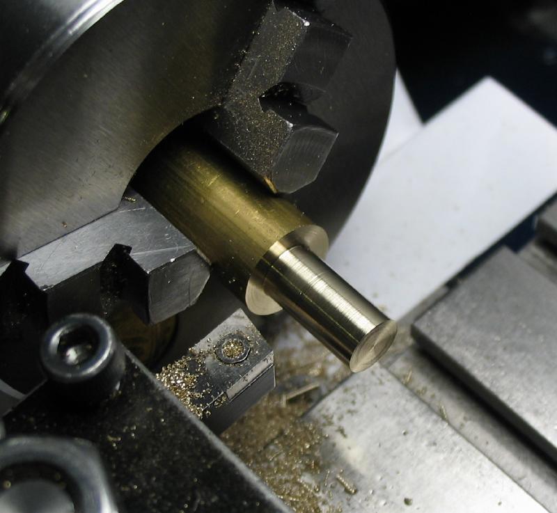
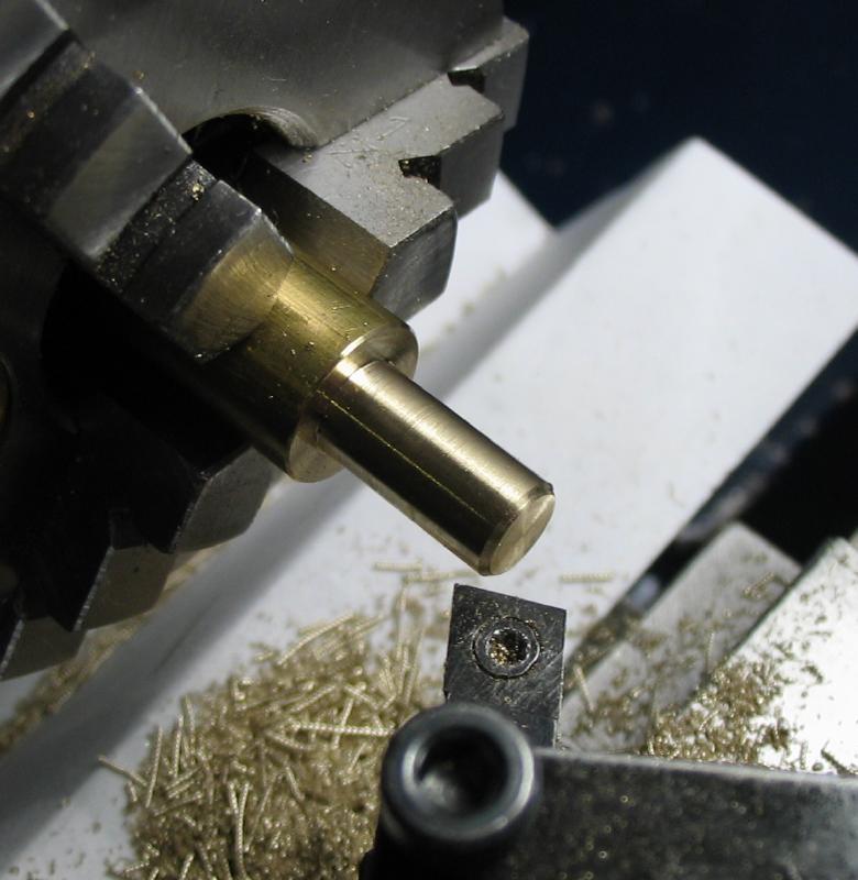
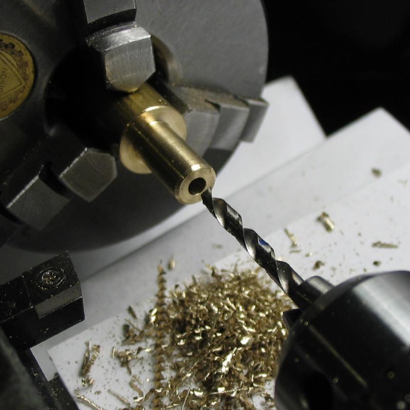
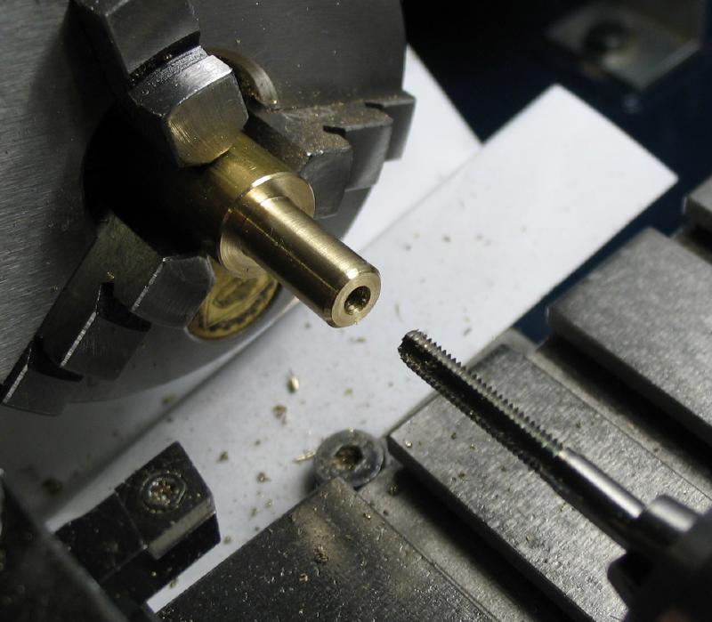
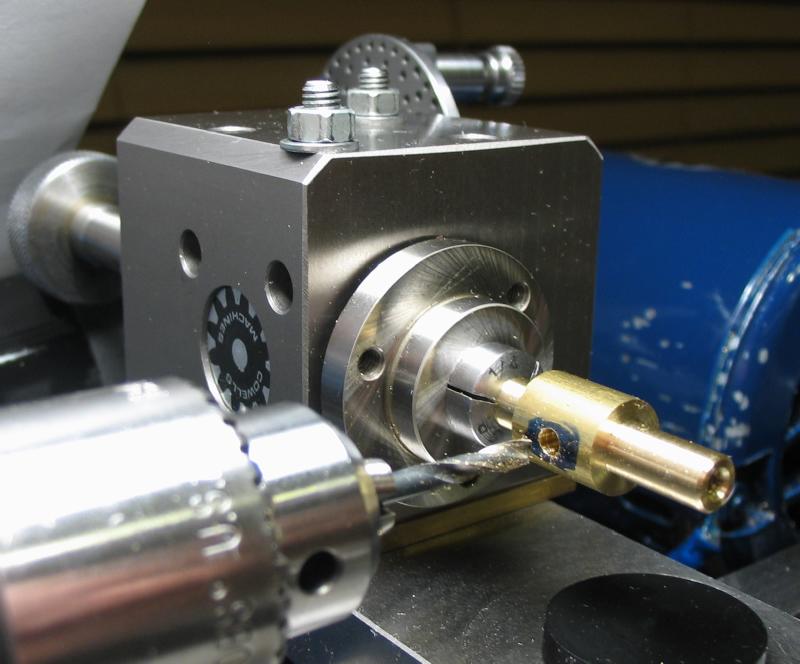
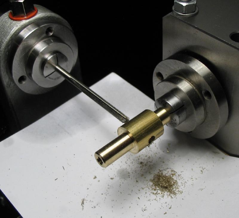
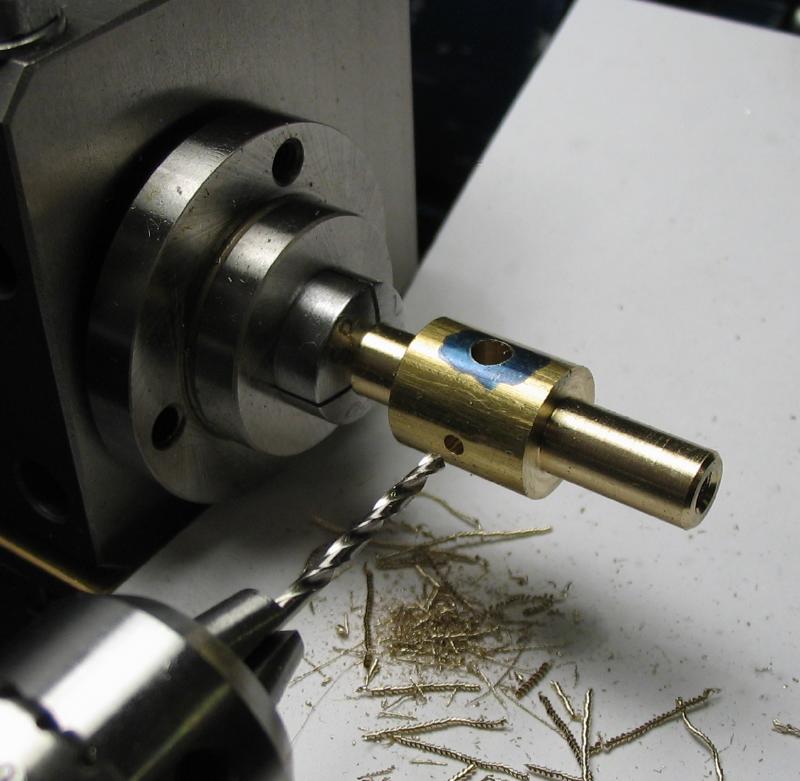
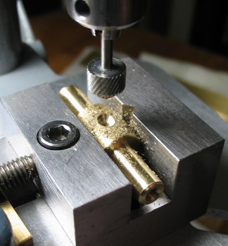
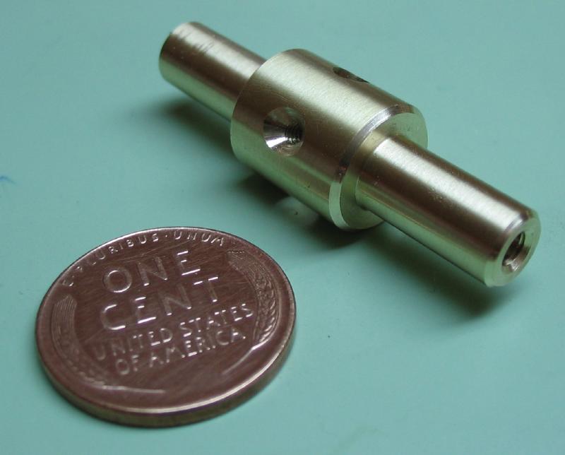
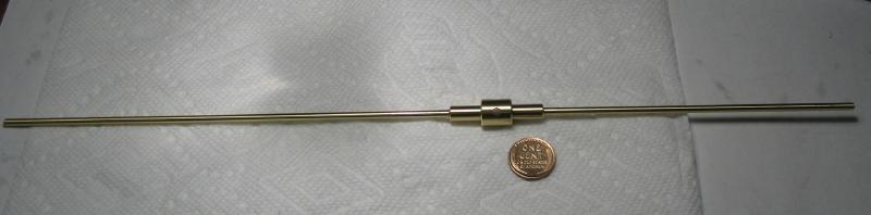
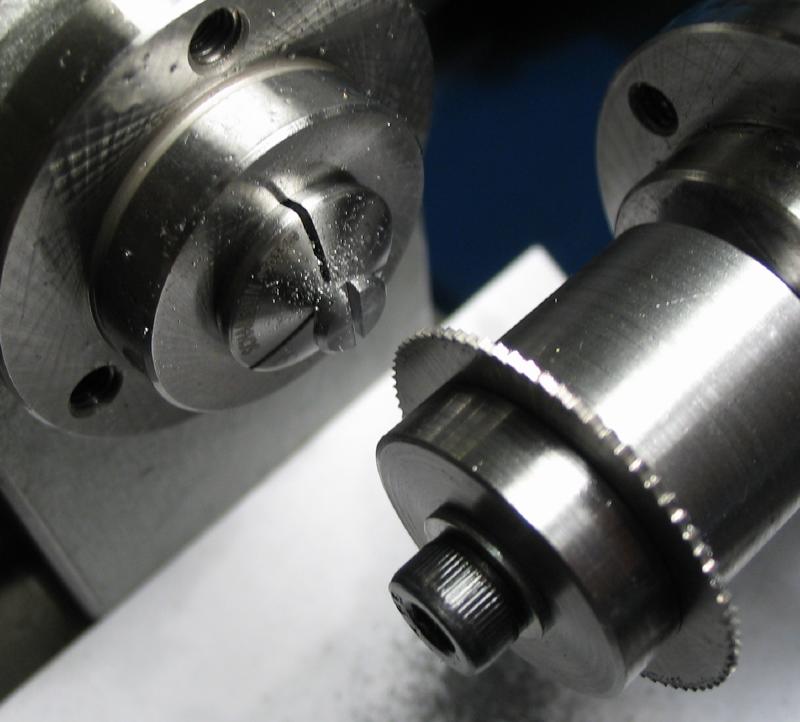
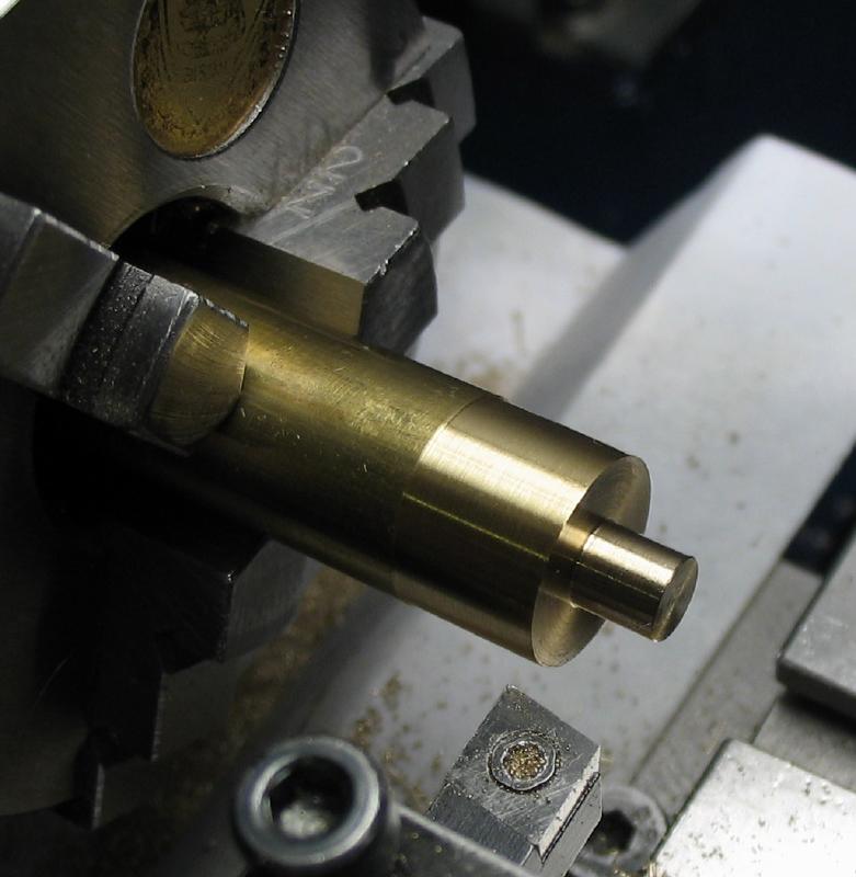
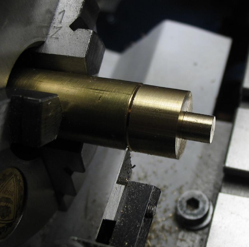
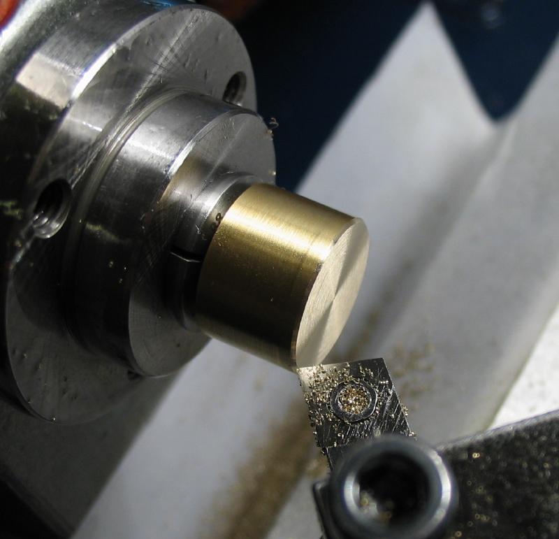
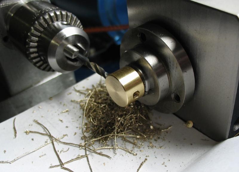
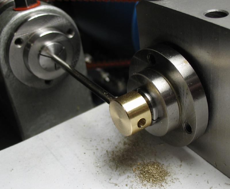
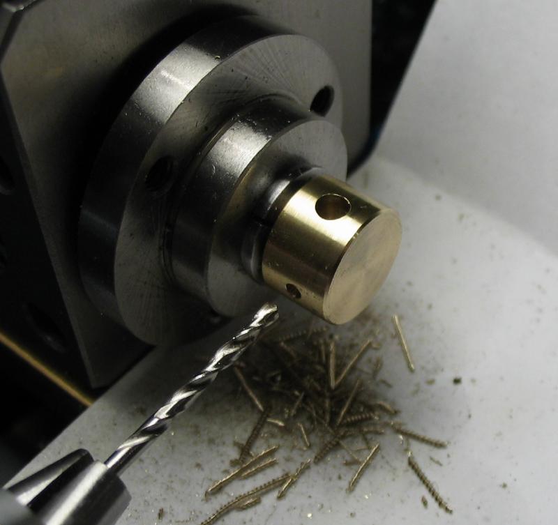
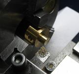
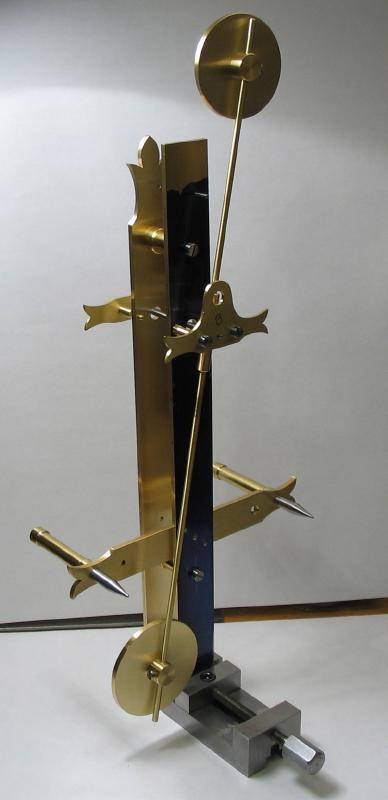
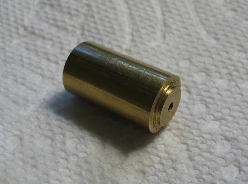
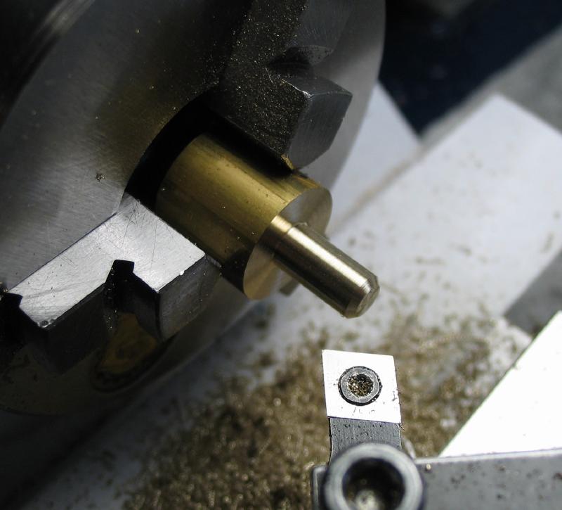
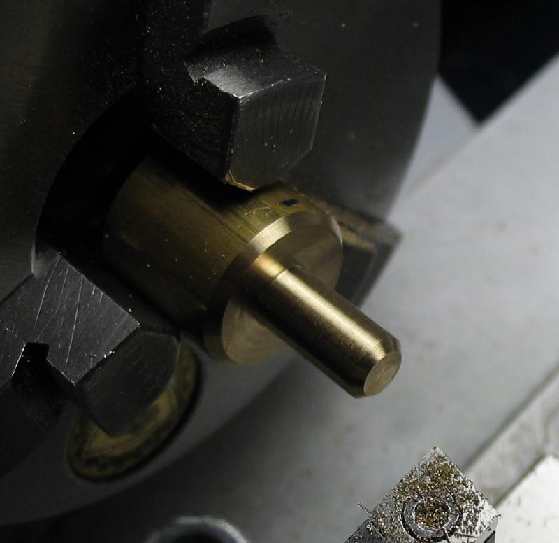
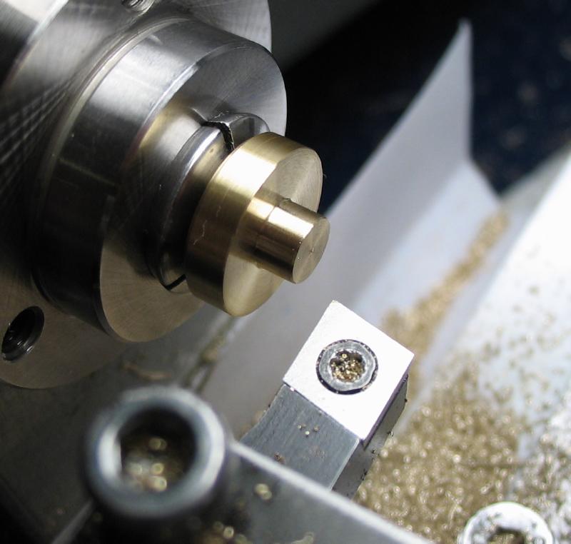
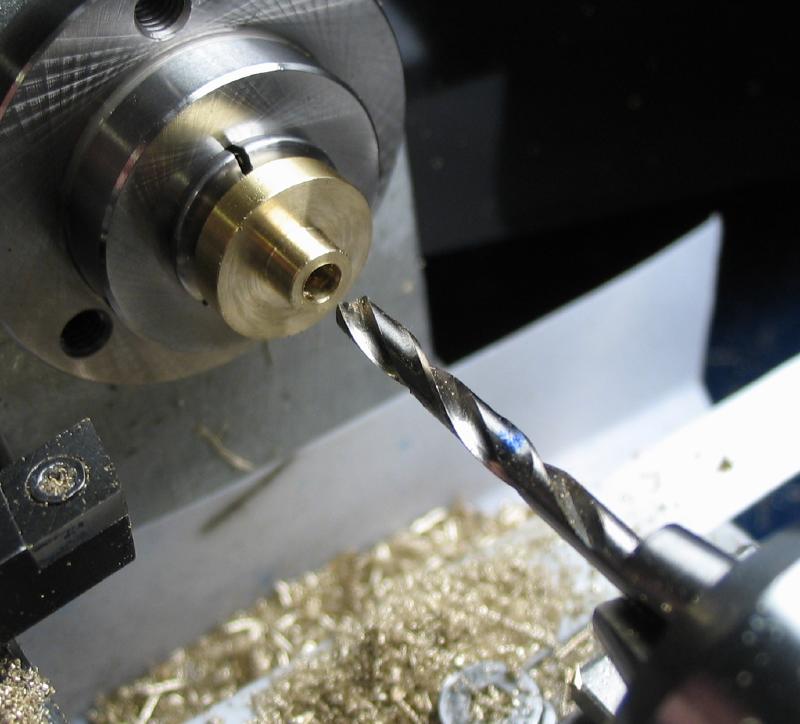
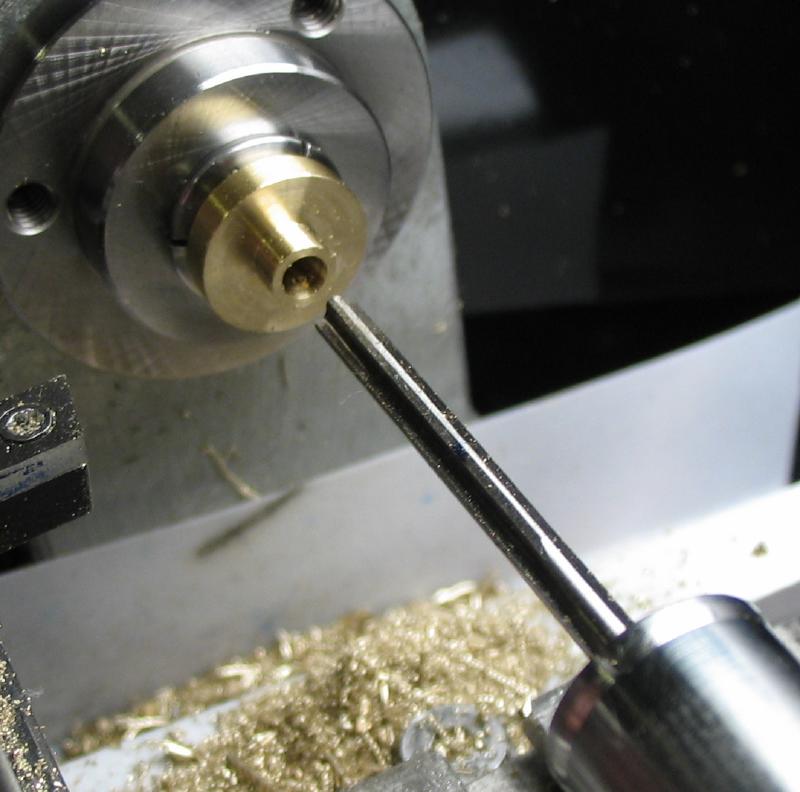
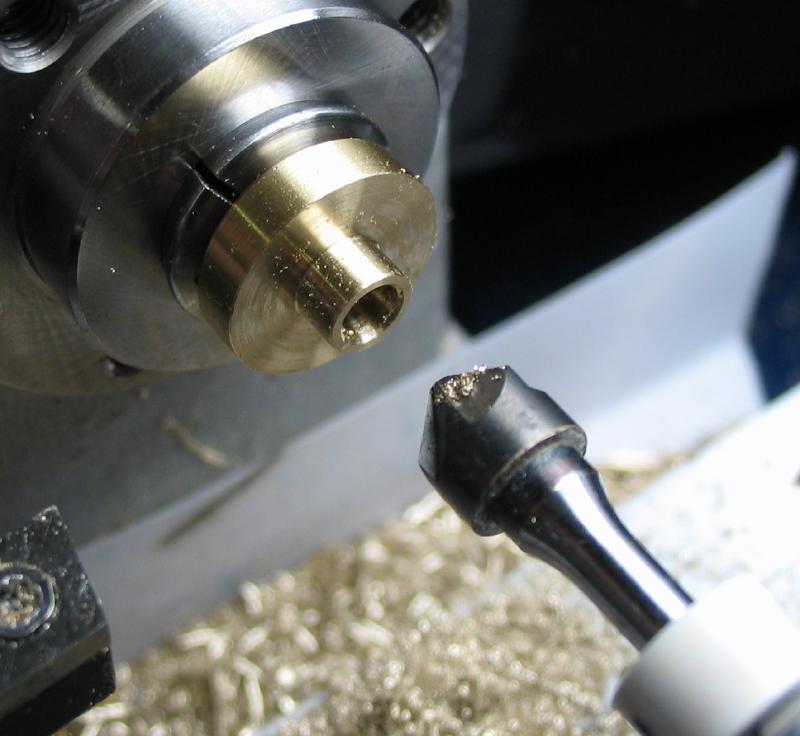
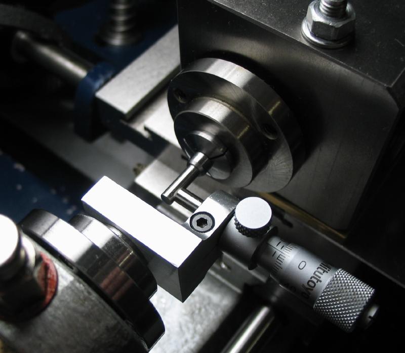
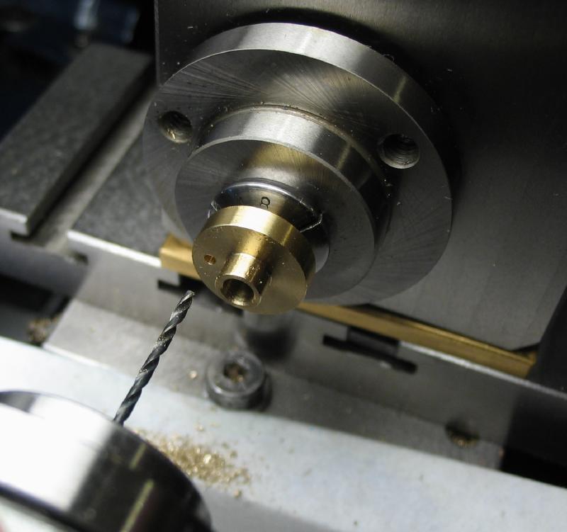
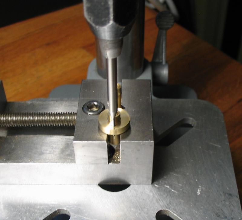
The pendulum rod collet was made from brass rod. Each end was turned, drilled, and tapped for the two pendulum rods. The center was cross drilled and reamed for the arbor and drilled and tapped for a set screw.
|
|
|
|
|
|
|
|
|
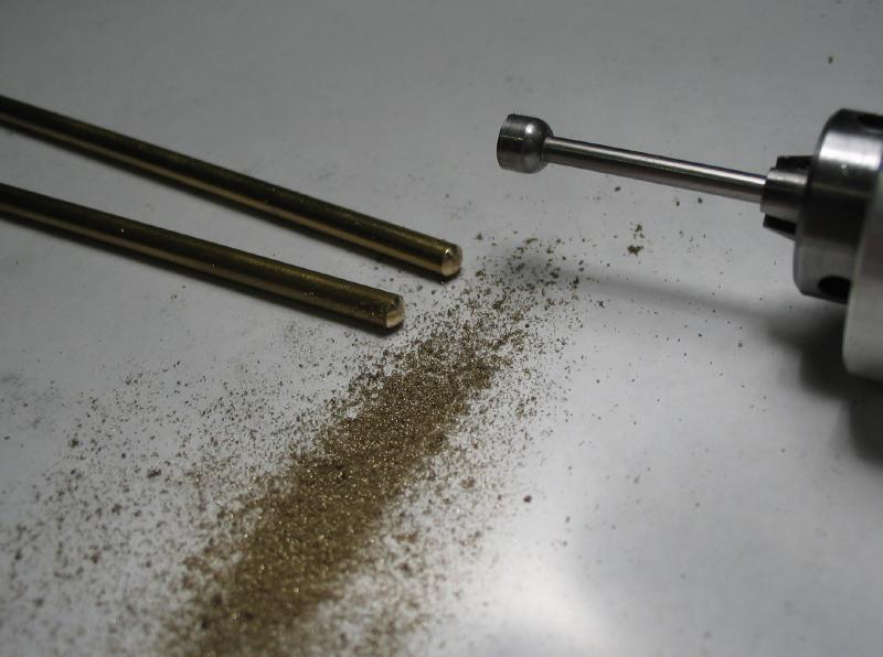
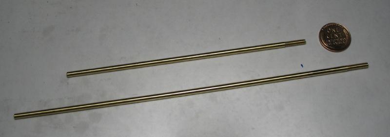
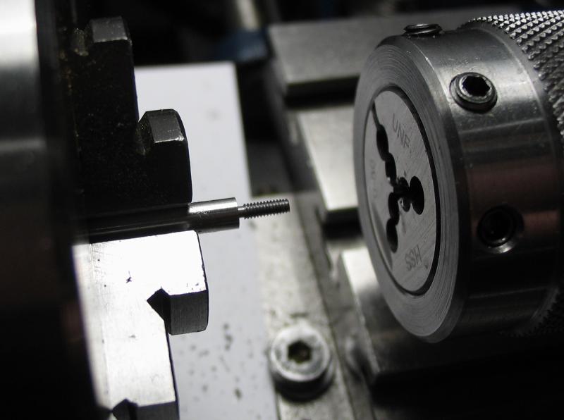
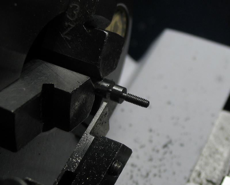
The pendulum rods were sawed off to the desired length and the ends rounded over with a cup bur. One end is threaded #5-44, which can be applied directly to 1/8" diameter rod, however, turning off a 'couple thou' helps.
|

|
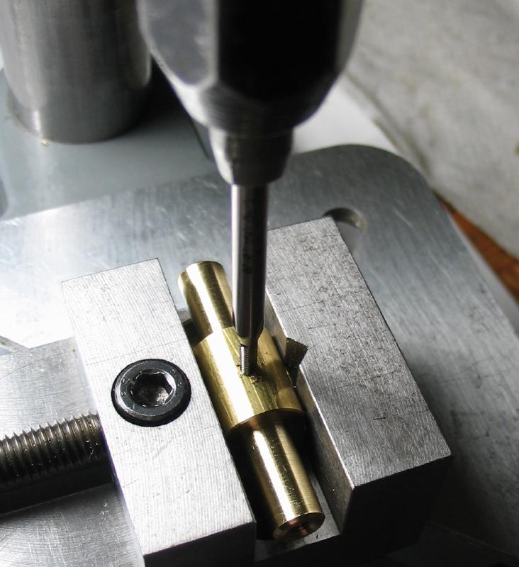
The countersunk set screw was made in a similar manner to any other screw, except the 90 degree countersink that was turned with the compound slide set 45 degrees. Three of these are required and the latter two are longer in length for the wider bob collets made below.
|
|
|
|

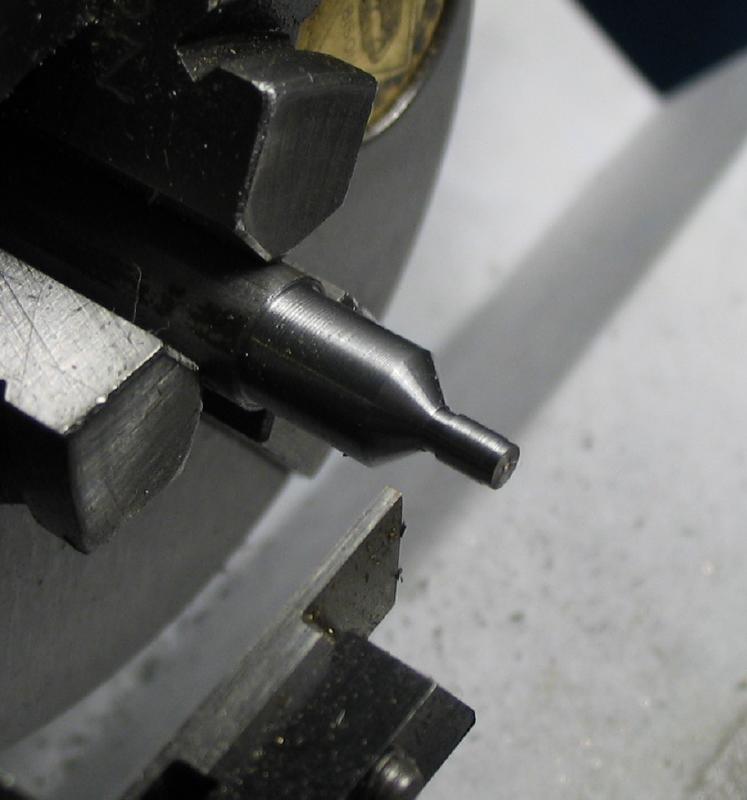
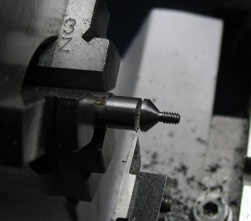
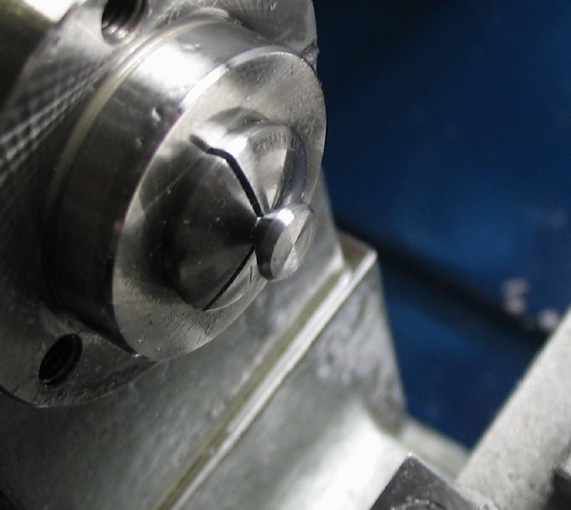
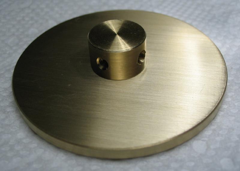
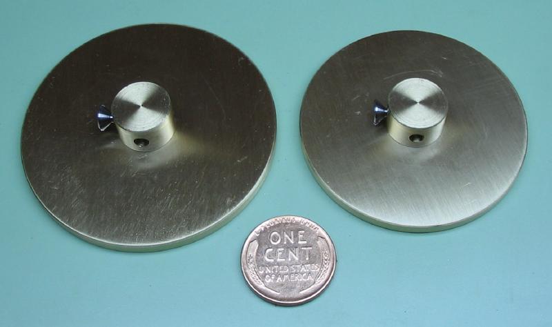
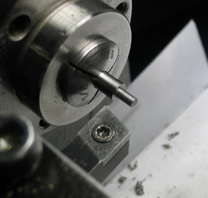
The two bob collets were made from brass rod. A boss was turned that will friction fit into a hole in the bob, and I used 5mm instead of 3/16" since I did not have a lathe collet for the latter. The boss is oversized in length to provide a firm grip when chucking this end. The work parted off and the parted face turned and chamfered, and the work moved to the dividing head to cross drill and ream to fit the pendulum rod and a also drilled and tapped for set screws. The boss can then be reduced in length, although still left a few tenths of a millimeter thicker than the bob material. The tapping and countersinking steps were not photographed, but was the same as above for the pendulum collet. Two countersunk set screws were made in the same manner as well, although slightly longer in thread length.
|
|
|
|
|
|
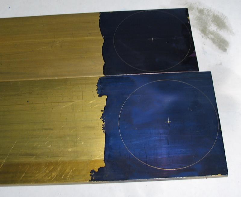
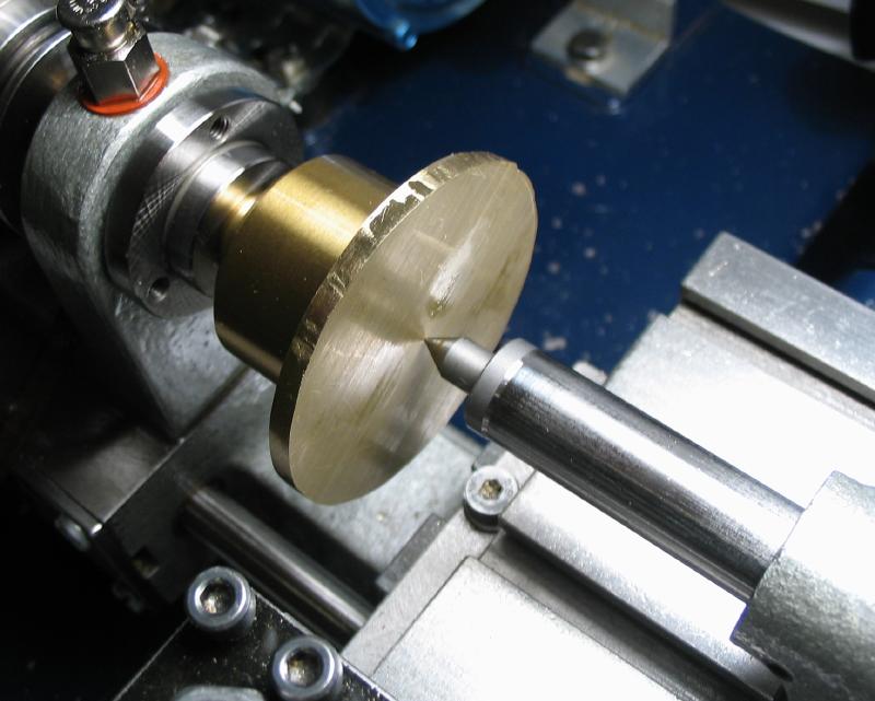
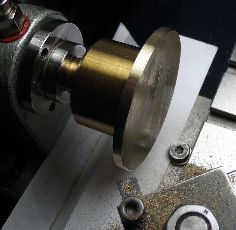
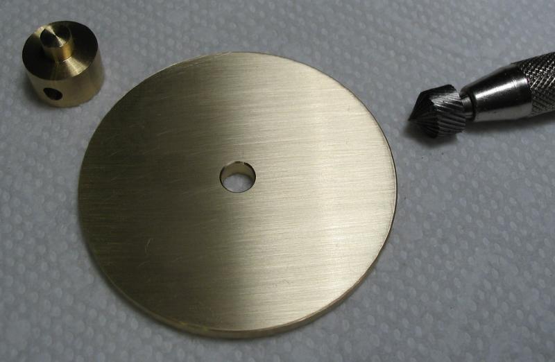
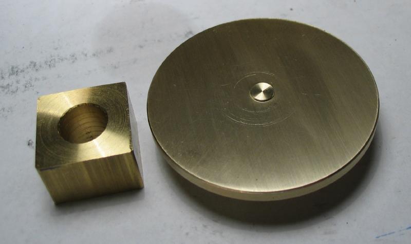
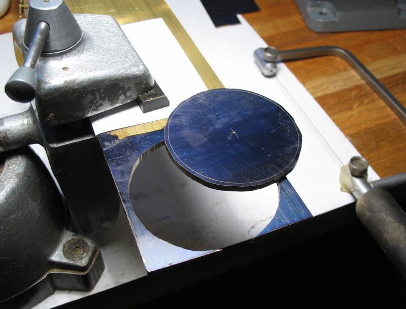
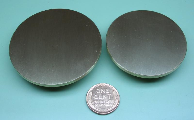
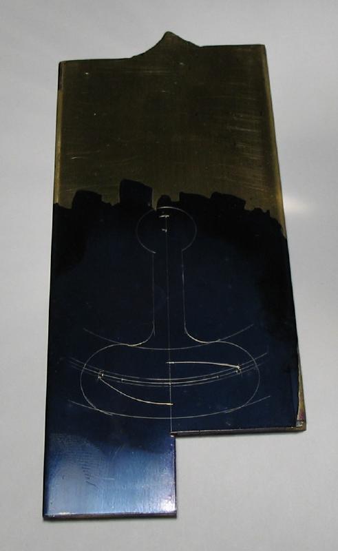
The bobs are sawed out from 1/8" thick brass plate. Mr. Wilding's design for the bobs are in the shape of an egg and egg-cup and he notes that their respective weights with their collets were 70 and 55 grams. Since I am deviating from the intended use for this timer, I chose a more simple design for the bobs, i.e. round discs. The exact weights may not be critical, however, in an attempt to keep them close to that described in Wilding's book, the brass stock was measured and weighed to determine the approximate density on a gram per square millimeter basis (the thickness was ignored since it will remain about the same). The nearly completed collets from above were weighed and then subtracted from the desired final bob weight. The weight needed was converted to mm² based on the density, and then the required radius solved from A=πr². The calculated radii are about 24 and 27mm, but while turning they were left about a half mm oversize to compensate for additional losses from the center hole, chamfering, facing, polishing, etc. The final weights of the bobs with their collets were 54.7g and 70.5g.
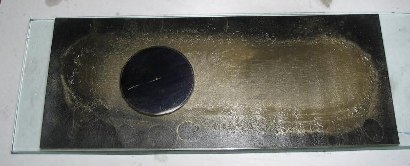
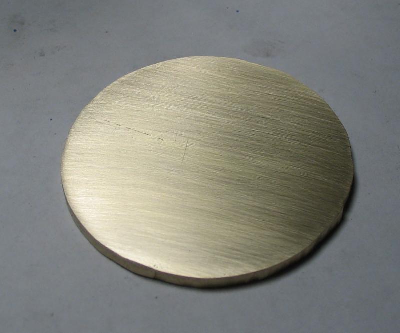
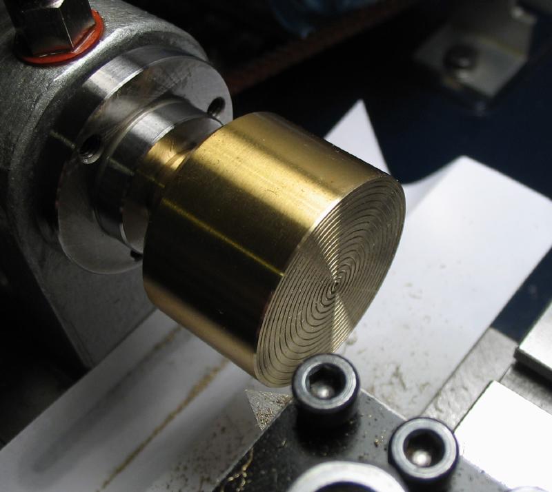
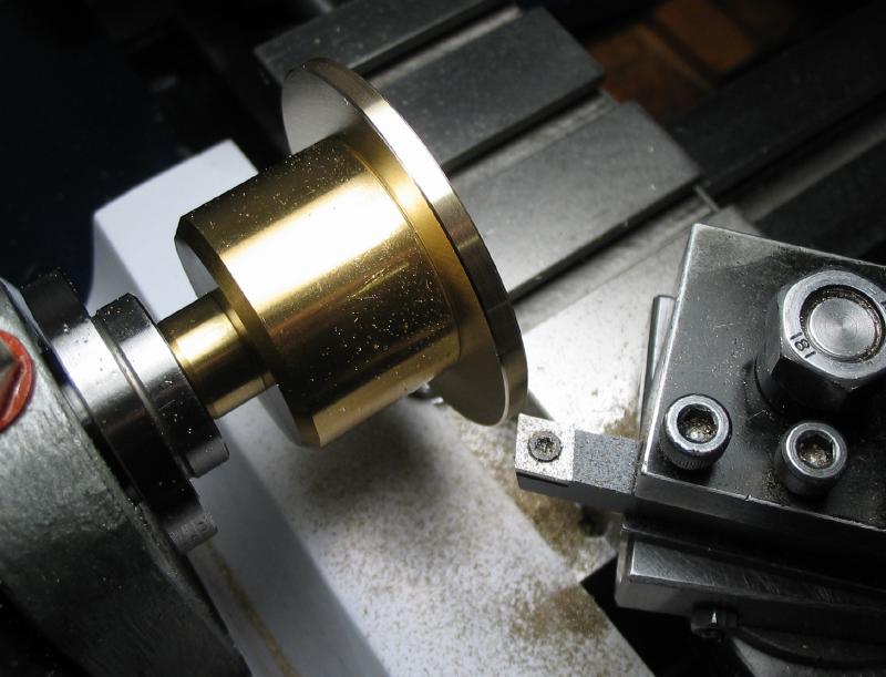
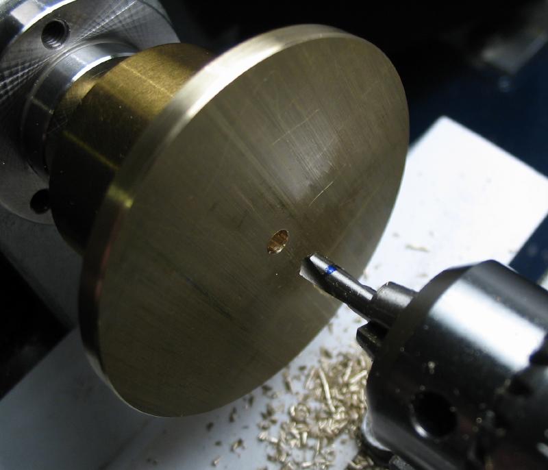
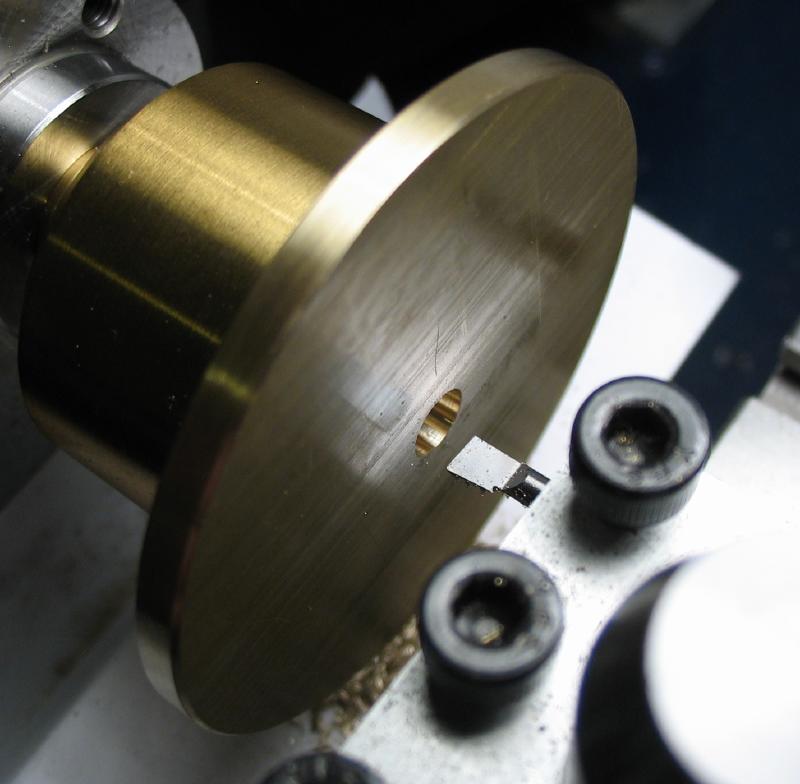
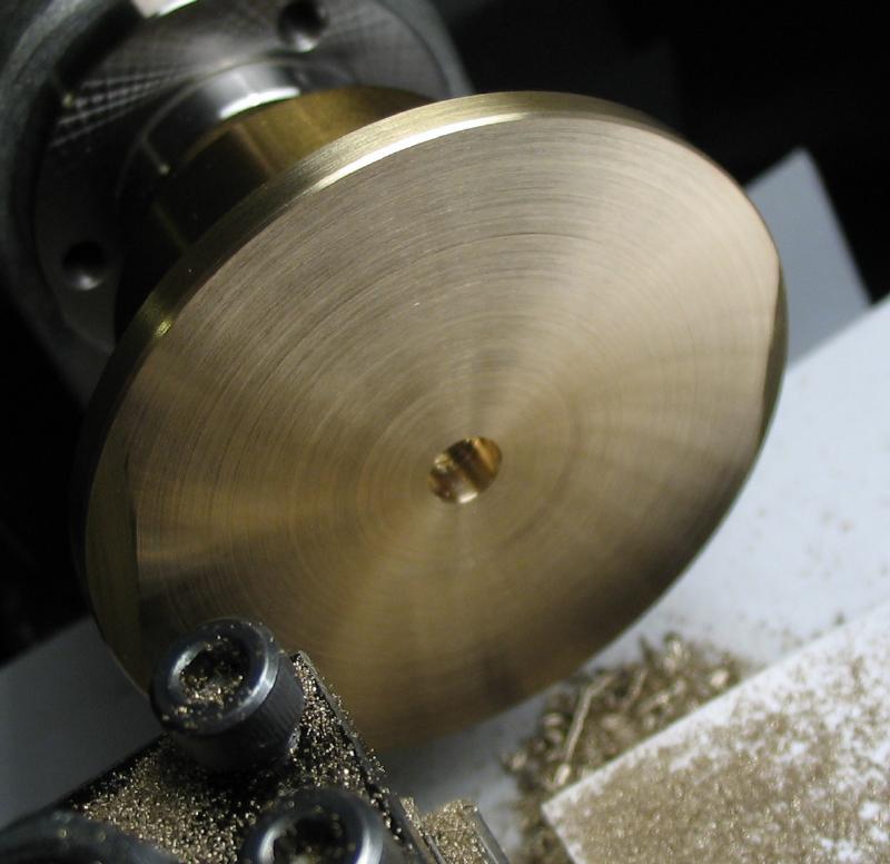
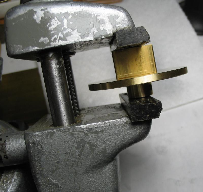
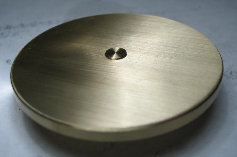
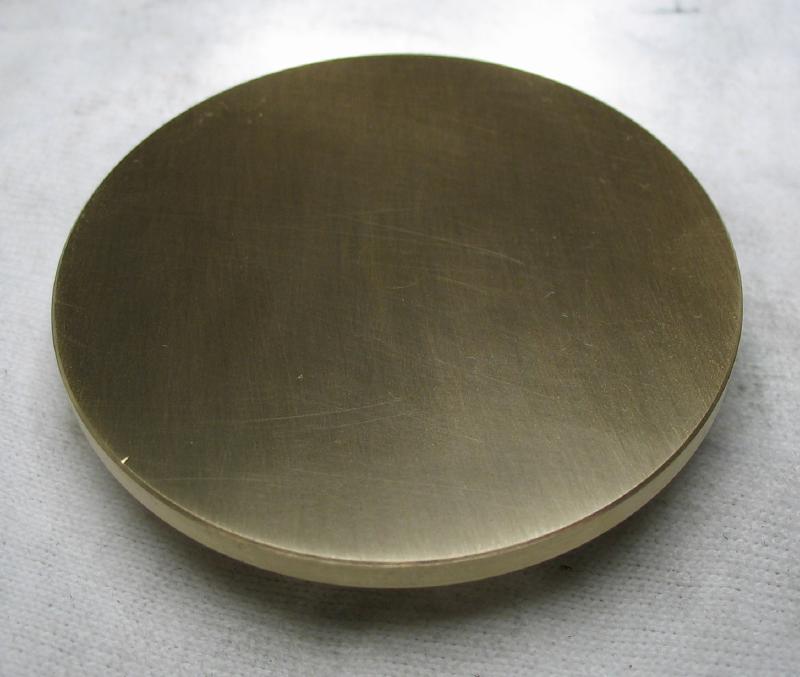
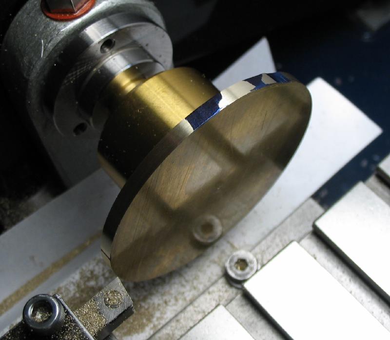
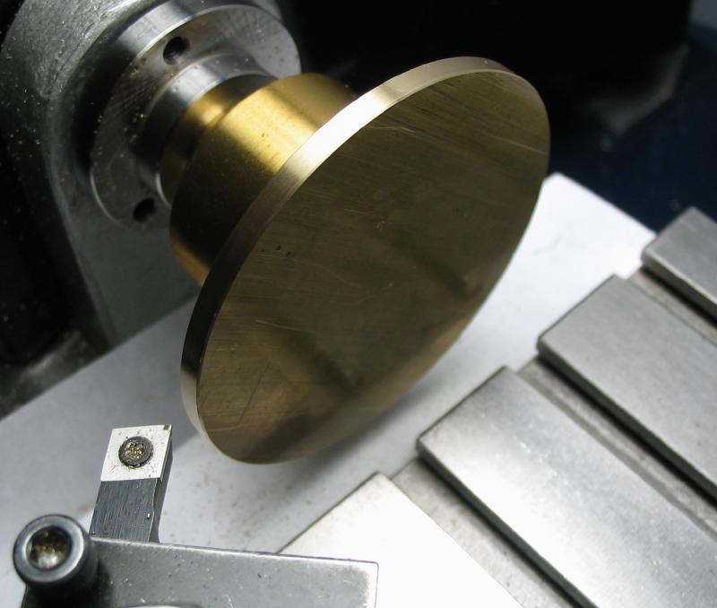
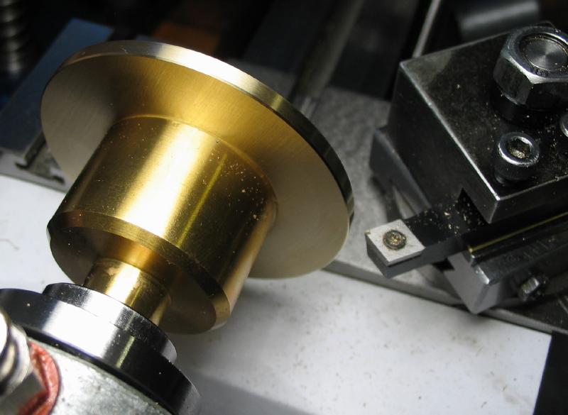
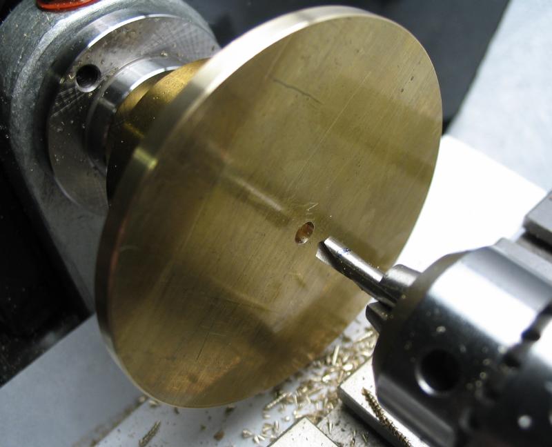
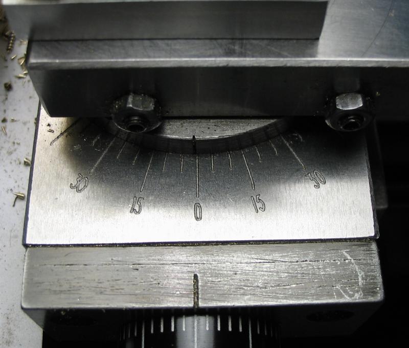
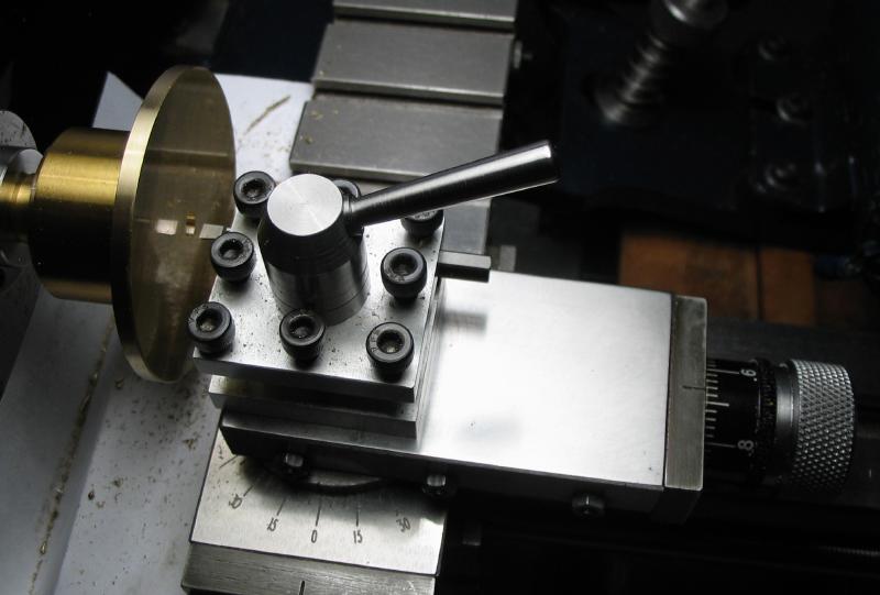
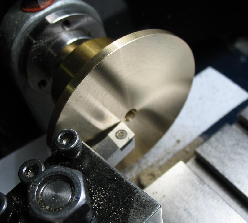
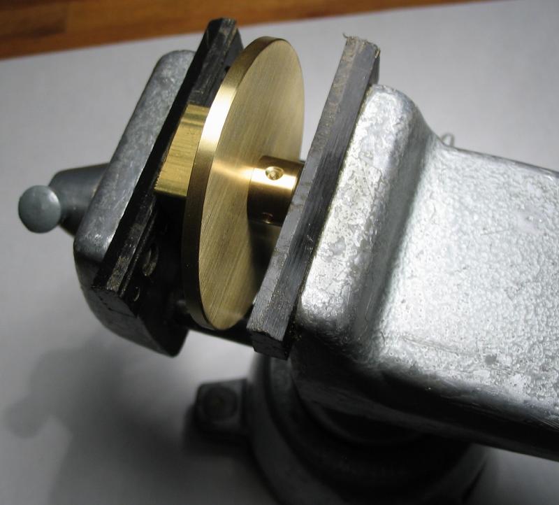
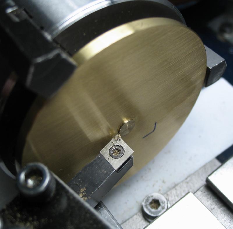
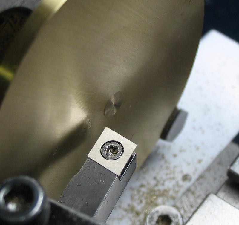
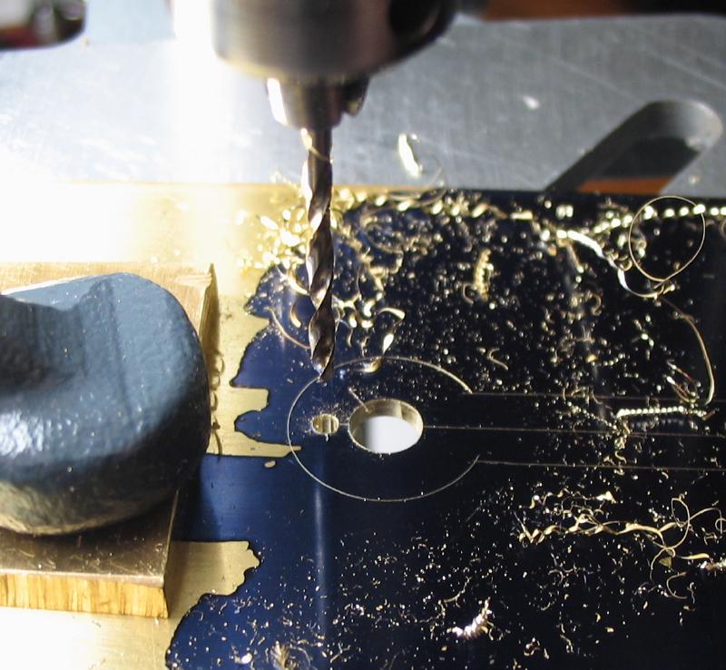
The circles were scribed on brass plate from a center punch mark and sawed out. The bottom face was smoothed with 400 grit emery paper on glass, and the rough disc then superglued to a brass cement chuck using the tailstock center in the punch mark for pressing the disc against the chuck and putting on lathe center. The disc was turned round and to the desired diameter and corners relieved with 45 degree chamfers. The center hole was formed by drilling a 1/8" pilot hole and then boring open with the top slide set at about 1 degree of taper and the hole expanded until the boss of the collet can be inserted about half way. The face was turned true, and the work removed from the chuck by heating with a torch to melt the glue. Both faces were smoothed with 400 and 800 grit emery paper. The hole was countersunk on the collet side, and the collet pressed in with the aid of a vise. A piece of scrap square brass that was flat and had a hole large enough to easily pass the boss of the collet since it exceeds the thickness of the bob. Afterward, the boss is turned flush with the face of the bob, and the whole surface smoothed again on emery paper. The joint of the collet and bob is almost invisible. Mr. Wilding recommends riveting prior to filing flush, however, the fit here was already very tight.
Photos while making the smaller bob
|
|
|
|
|
|
|
|
|
|
|
|
|
|
|

|
|
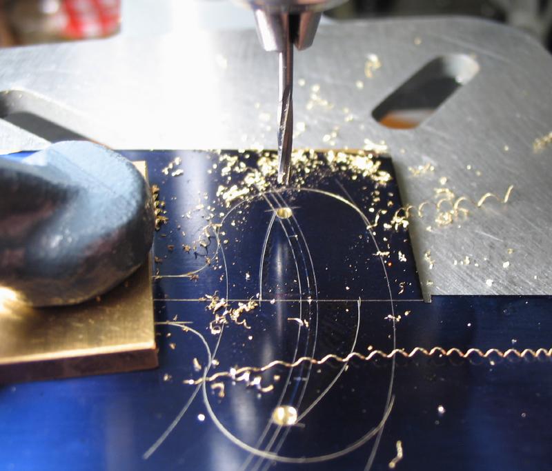
Photos while making the larger bob.
|
|
|
|
|
|
|
|
|
|
|
|
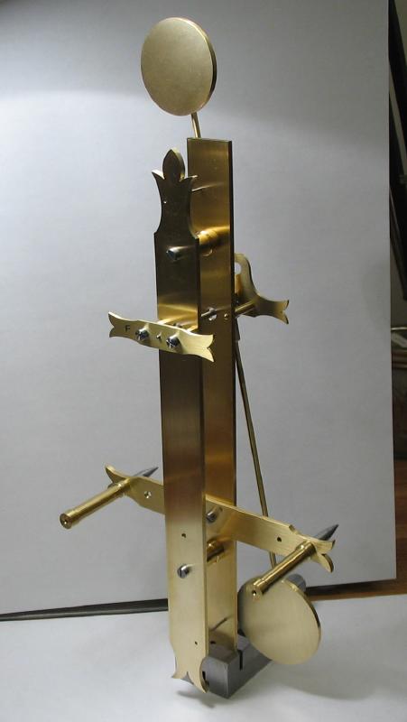
Photos after all machining complete on bobs and assembled on the pendulum rod.
|
|
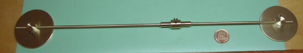

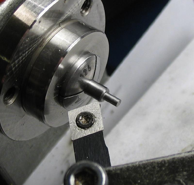
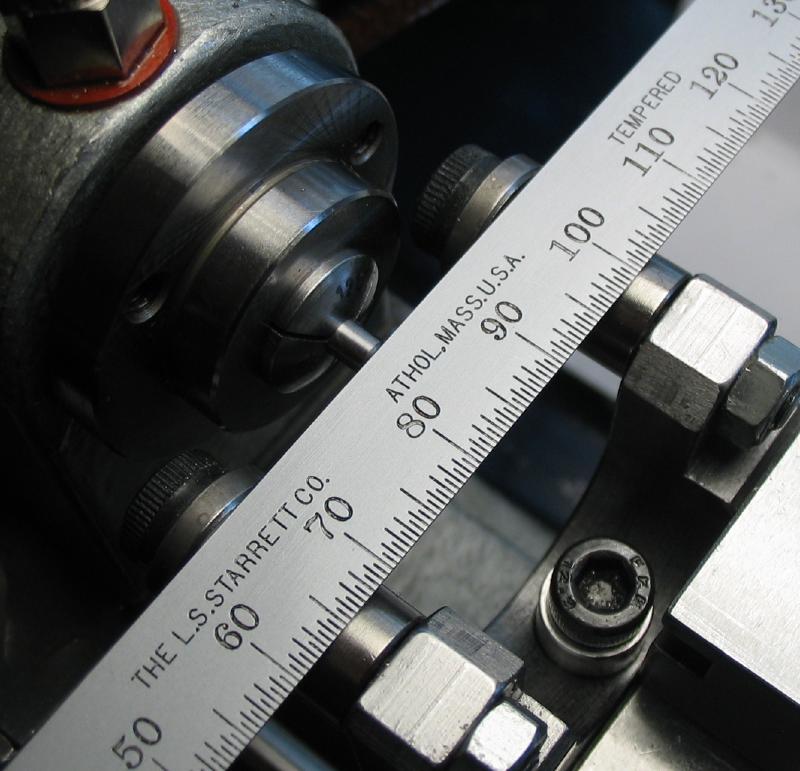
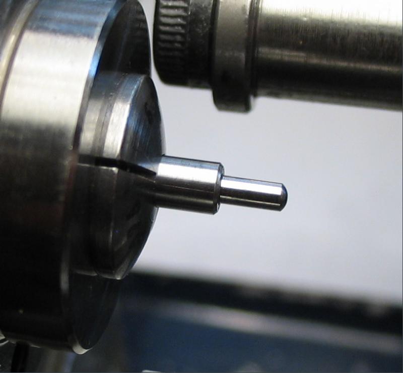
The pendulum arbor was made from 1/8" steel rod. Mr. Wiling describes using mild steel for the various arbors, but I decided on drill rod. One pivot is turned to about 1.65mm, corner chamfered 45 degrees and the tip rounded over with a cup bur. The length of the arbor and location for the other pivot can be taken from the assembled frame and bridges. The first pivot is placed against the inside face of a bridge and the other end laid against the other bridge and a mark made with the edge of a scraper. The inside faces of the bridges were measured with the calipers as a double check. This length will need a small amount of endshake substracted, which is Wilding recommends to be about 0.4-0.8mm. The other pivot is formed in the same manner and with the roller filing rest installed, the pivot finish was improved with an Arkansas stone and Vallorbe burnisher that was prepared (i.e., "made") on emery paper .
|
|

|
|

|

|
|
|

|
|
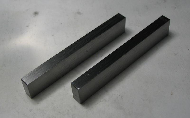
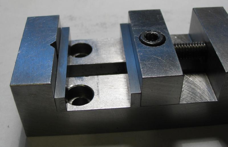
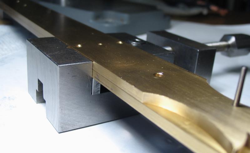
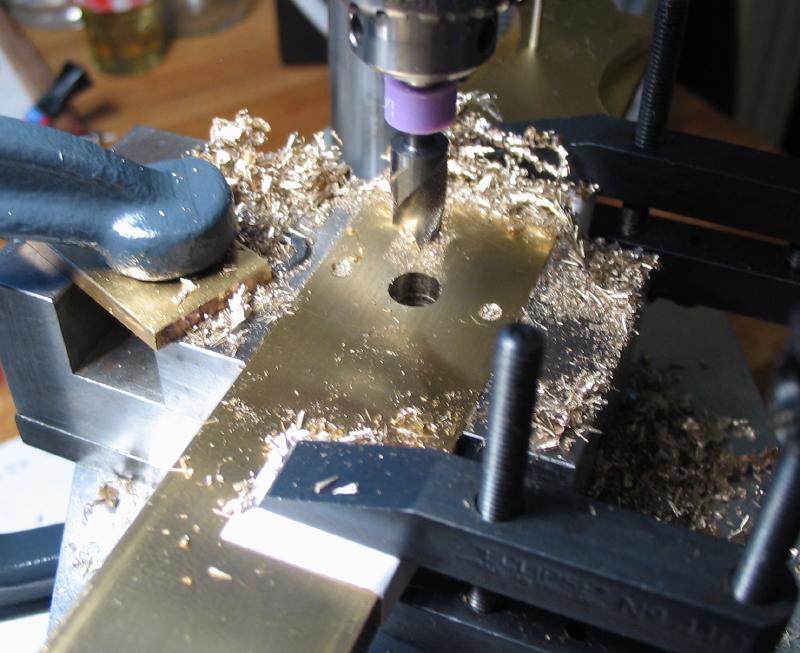
The mainplates were assembled and drilled through to clear the pendulum arbor. The plates were clamped and set up in a vise to keep aligned and together. A set of parallels for the vise were made from 1/8"x1/4" tool steel to raise the work and provide clearance for the drill bit.
|
|
|
The bridges were broached to fit the arbor pivots. Tools used are shown, Bergeon cutting and smoothing broaches and pin vise for a handle. A small setting but was used to countersink the hole as well. The cutting broach is applied from the inside until the pivot will just enter and the smoothing broach applied which slightly expands the hole and smooths the surface.
|

|
Test fit of components at this stage. The taper pin in the mainplate is preventing the pendulum from passing.
|
|
The pallet arm collet was made from a short length of 1/2" brass rod scrap. The back end is turned first, which is then held in a lathe collet for machining the seat for the pallet and drilling and reaming to fit the arbor. The position for a screw was drilled with the work set up in the dividing head, however, this should be drilled at the same time as the pallet arm to assure alignment.
|
|
|
|
|
|
|
|
|
|
Screw for pallet arm and collet made from oil hardening drill rod in #0-80 threads.
|
|
Pallet Arm
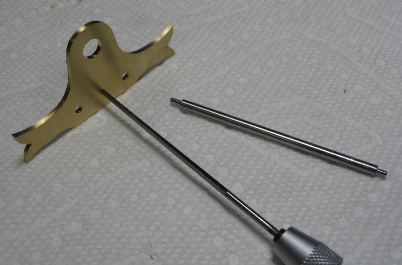
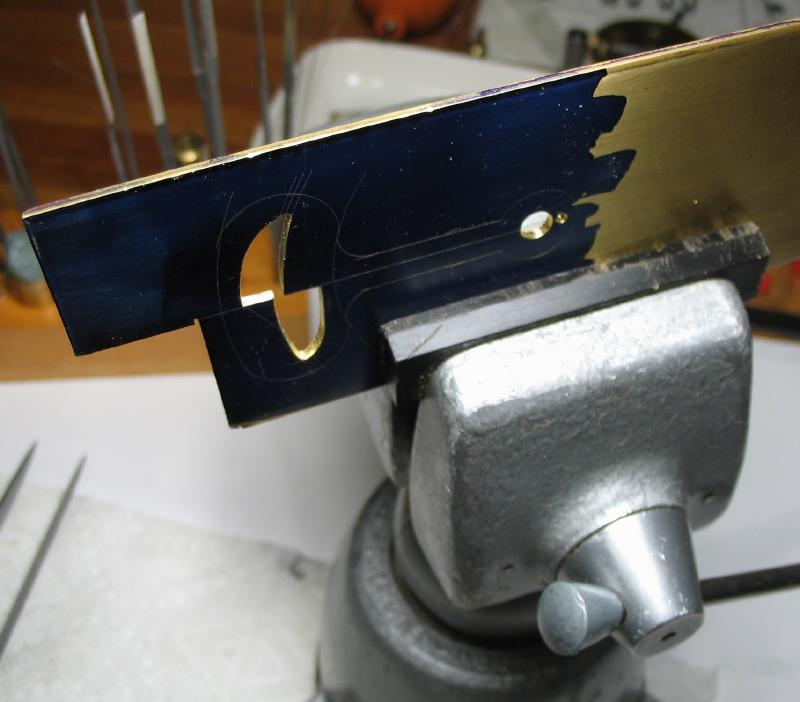
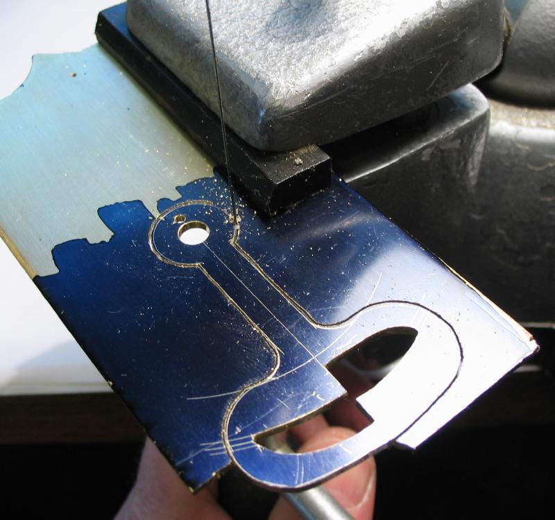
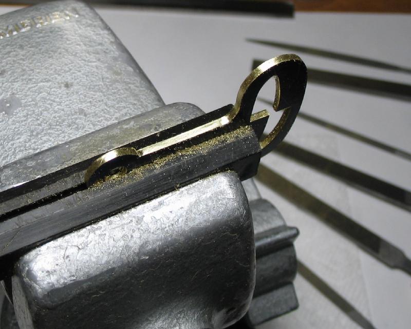
The shape of the pallet arm was scribed on 1/16" brass plate and the mounting holes drilled and extreme ends of the slot drilled and reamed. The slot was sawed out and filed to shape with careful attention paid to the acting surfaces, which were draw filed with no. 6 files to smooth and then finished with a hardened steel burnisher (made below). The general shape is then sawed out and filed to finish.
|
|
|
|
|
|
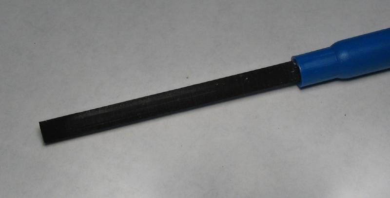
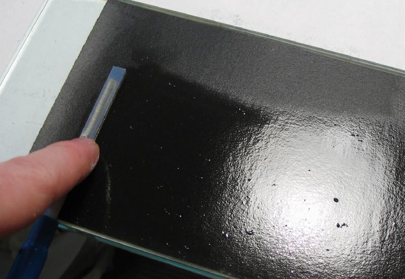
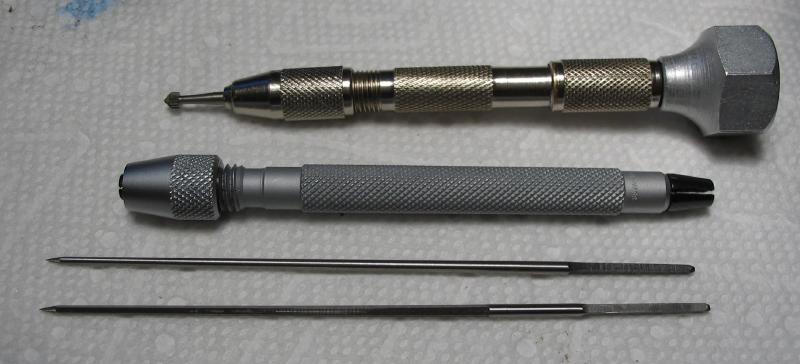
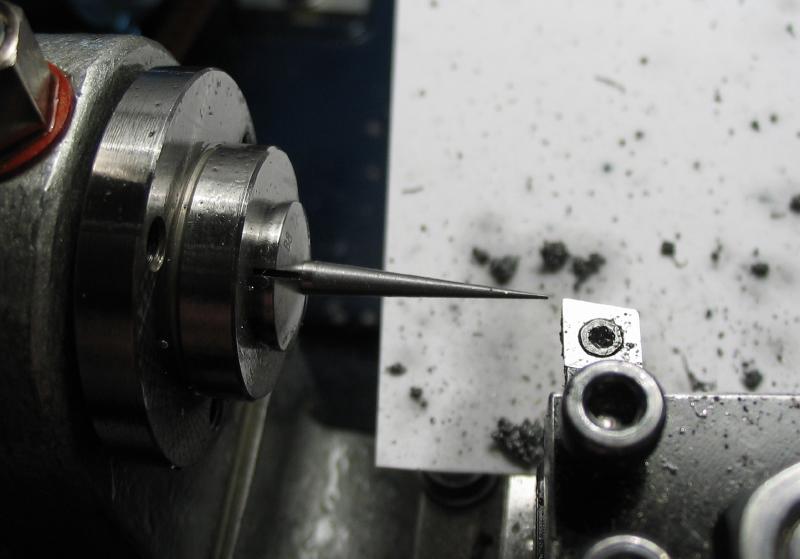
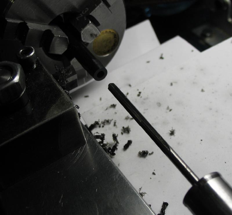
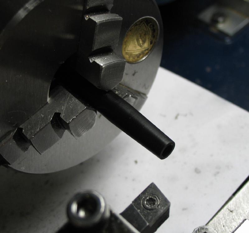
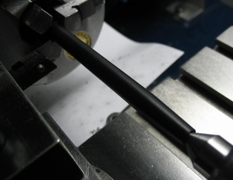
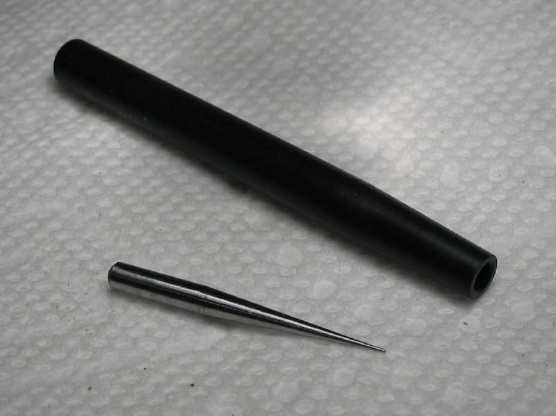
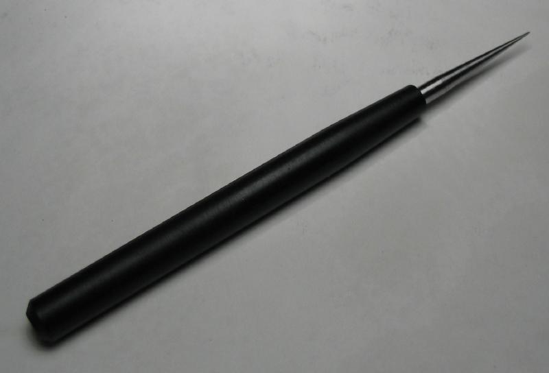
It is recommended to burnish the working surfaces and a small burnishing tool was made for such purposes. Mr. Wilding shows the use of a sewing needle held in a dowel handle, a something similar was made. A short length of 3mm drill rod was turned with a taper of a few degrees (it was adjusted as needed until the exposed length was turned), and it was hardeded and then stoned fairly smooth. The handle is 1/4 delrin rod that was reamed to fit the shank of the bit just made and given a slight taper as well. The fit was very tight so no adhesive was employed although it was the plan, but is a advantage since the tip can be removed and sharpened/stoned on the lathe.
|
|
|
|
|
|
