Mainplates
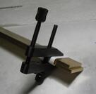
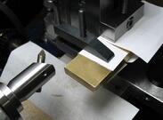
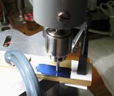
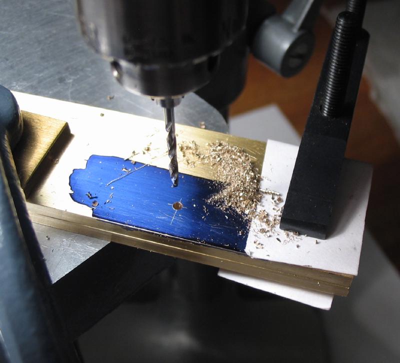
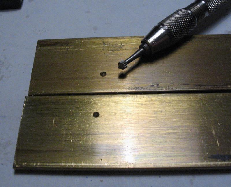
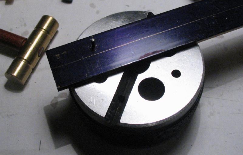
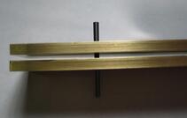
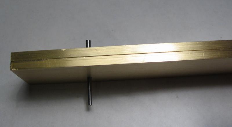
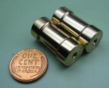
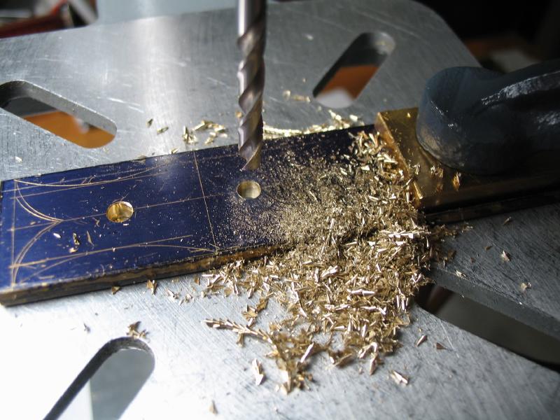
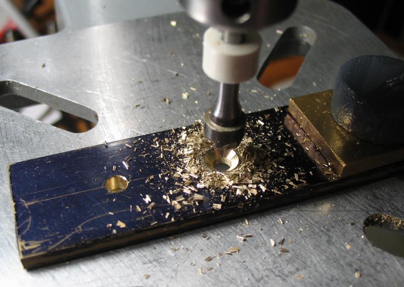
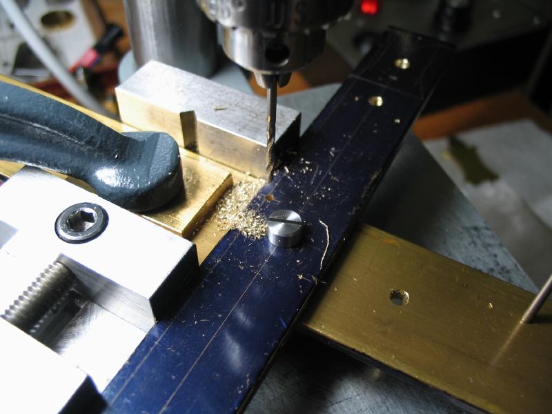
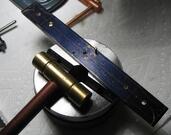
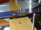
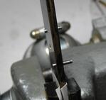
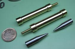
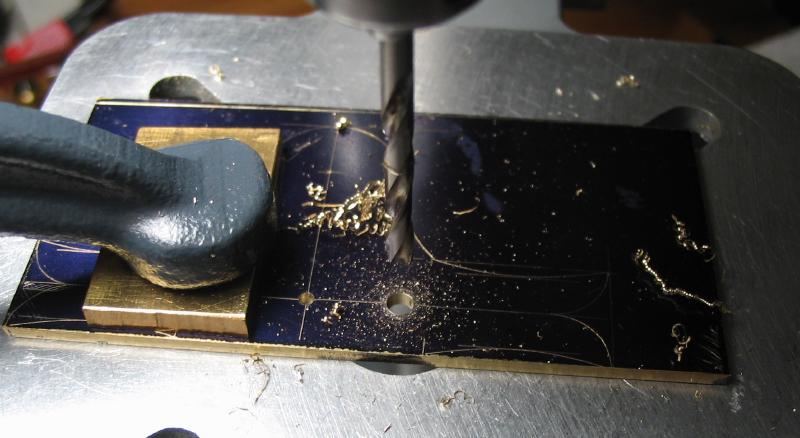
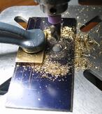
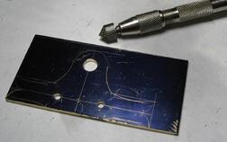
The work was started with the primary structural components, beginning with the main plates. The front and back plates began as 1 foot lengths of 1/8" x 1" brass bar (360 type). The brass bars were clamped together and milled to the same length. A center line was decided on and location of two taper pins were also laid out and center punched. The positions for register pins were drilled and reamed with a taper pin reamer. The tapered holes could be formed with a tapered cutting broach, but the #5/0 pin reamer and matching taper pins shown below work nicely. The pins are installed one at a time. After hammering a pin into the back plate, it will no longer fit the hole in the front plate, so there will be gap when fitting the plates together. The hole is reamed or broached in very small increments until the pin will seat the plates snugly together. The holes were countersunk just to remove the small bur around the edge that can prevent a good fit. The second pin is then installed in the same manner. The pins were left in their original full length as they will eventually be removed and the holes plugged, but they will serve as the way of aligning the plates for various steps throughout construction.
The work was started with the primary structural components, beginning with the main plates. The front and back plates began as 1 foot lengths of 1/8" x 1" brass bar (360 type). The brass bars were clamped together and milled to the same length. A center line was decided on and location of two taper pins were also laid out and center punched. The positions for register pins were drilled and reamed with a taper pin reamer. The tapered holes could be formed with a tapered cutting broach, but the #5/0 pin reamer and matching taper pins shown below work nicely. The pins are installed one at a time. After hammering a pin into the back plate, it will no longer fit the hole in the front plate, so there will be gap when fitting the plates together. The hole is reamed or broached in very small increments until the pin will seat the plates snugly together. The holes were countersunk just to remove the small bur around the edge that can prevent a good fit. The second pin is then installed in the same manner. The pins were left in their original full length as they will eventually be removed and the holes plugged, but they will serve as the way of aligning the plates for various steps throughout construction.
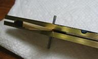
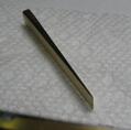
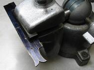
The fit the plates together was tight enough that it was difficult to separate, so a simple wedge was fashioned from a scrap piece of brass that can be used to separate the plates.
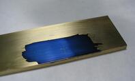
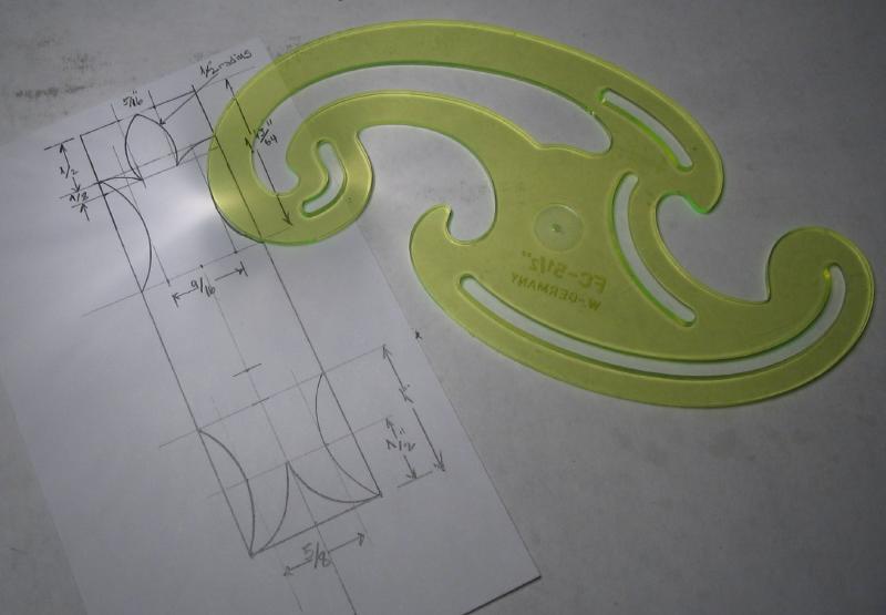
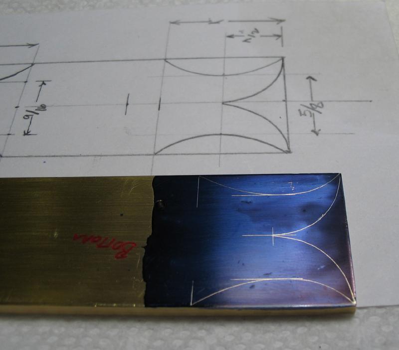
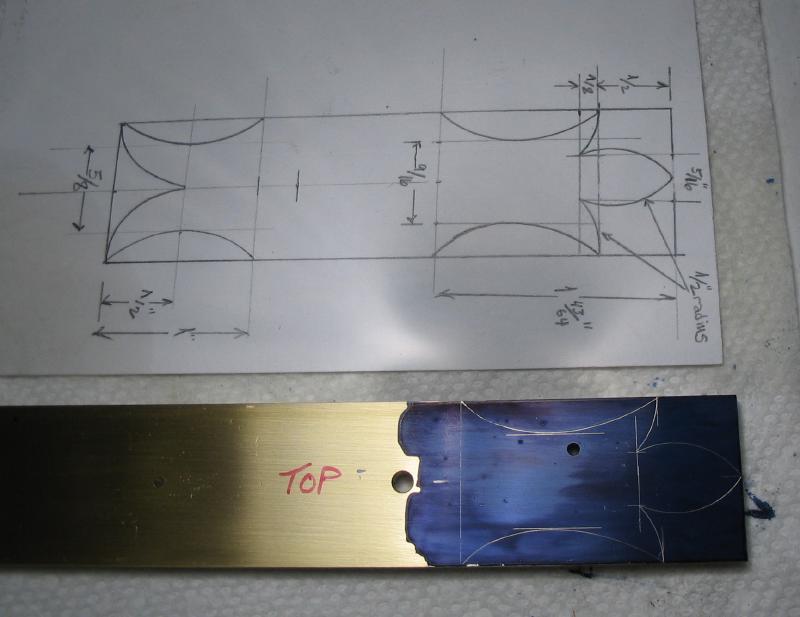
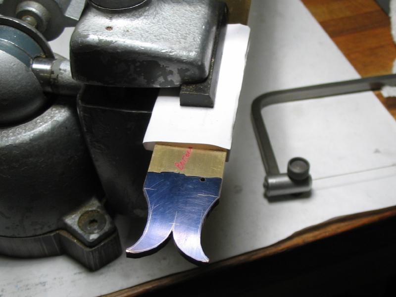
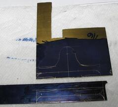
The front plate, as well as a few other components of the frame, have ornamental work. This is laid out with the aid of radius gauges and a French curve. The French curve is excellent for forming pleasant-looking arcs and curves that cannot be obtained with a compass or divider. I tried the design on paper first, and then repeated the process on brass, which was coated in layout blue. Guidelines for locating the intersections and tips are helpful when scribing the arcs. I am using the same design described in Mr. Wilding's book, which is somewhat reminiscent of a fleur-de-lys.
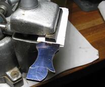
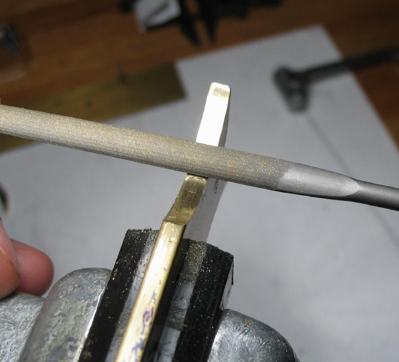
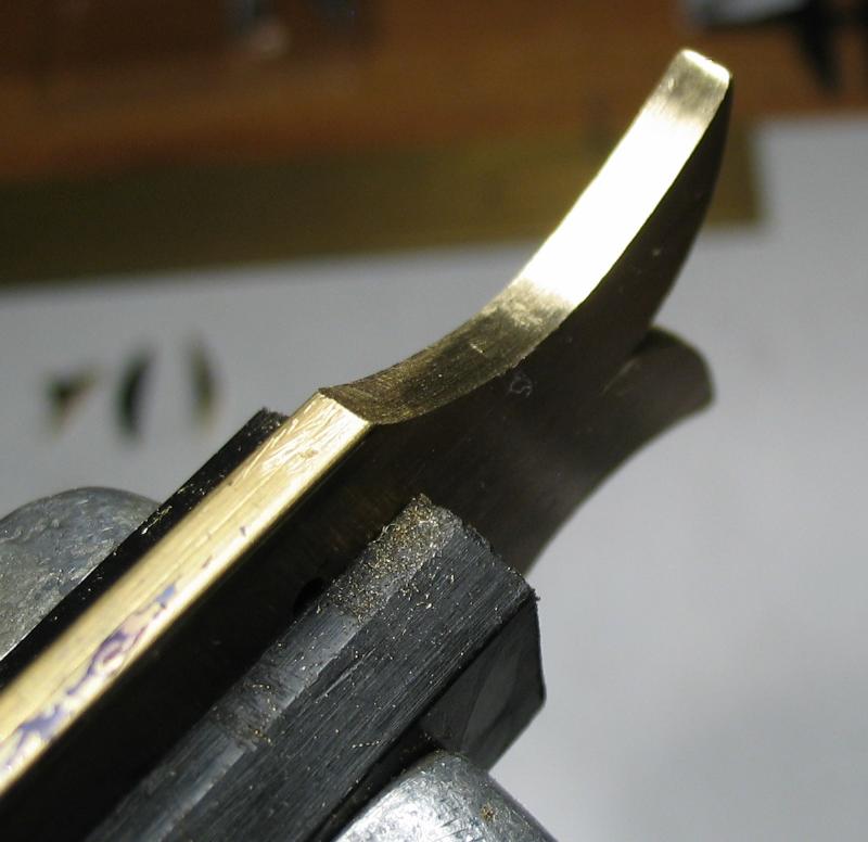
The design was cut out with a 4/0 size jewelers saw, and then brought to shape with various files. Crossing files served well in the rounded side regions and barrett files on the end curves and point. Mr. Wilding describes the use of a knife file with one edge ground smooth (i.e., safe). I experimented with these as well, but forming tight corners is certainly a challenge. Once close to the correct dimensions, the the surface is smoothed by "draw-filing" to get a uniform finish.
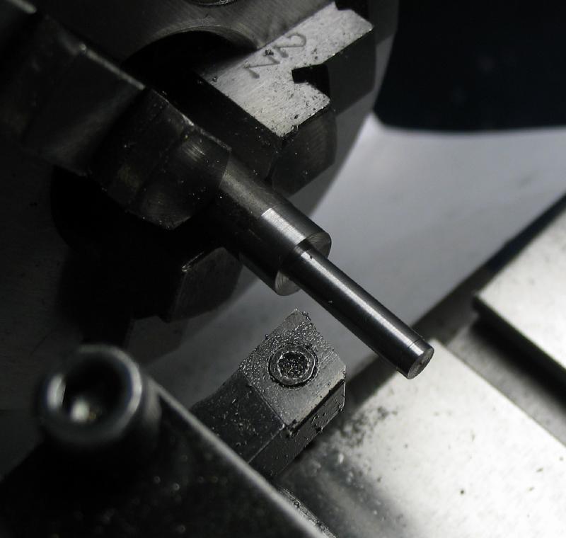
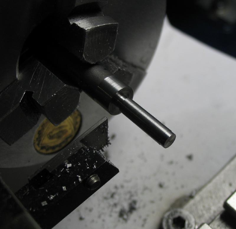
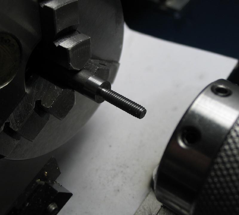
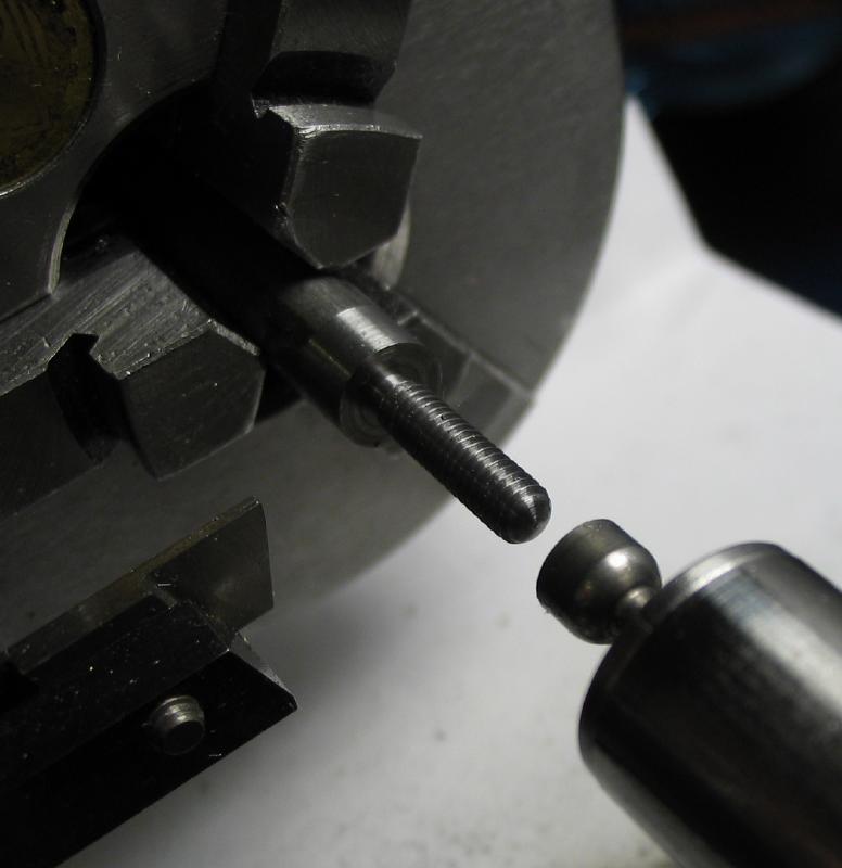
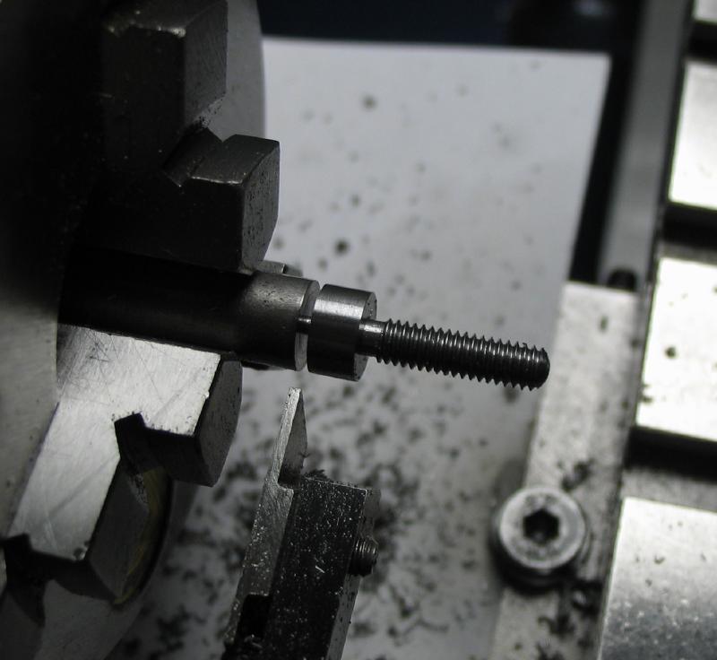
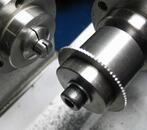
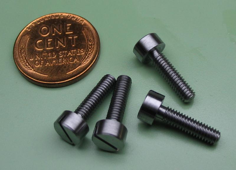
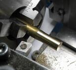
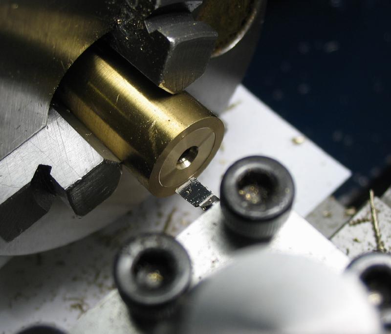
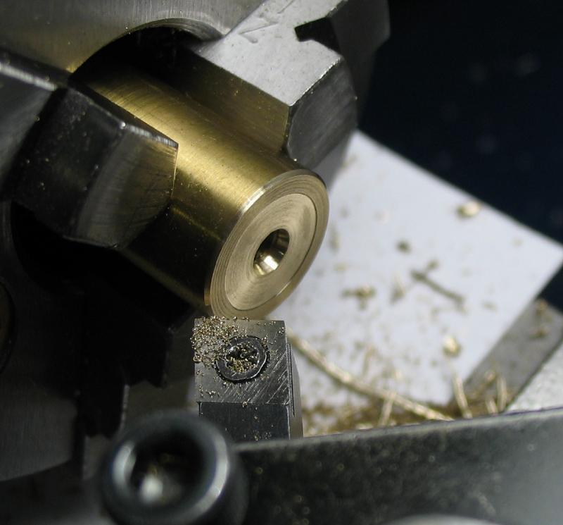
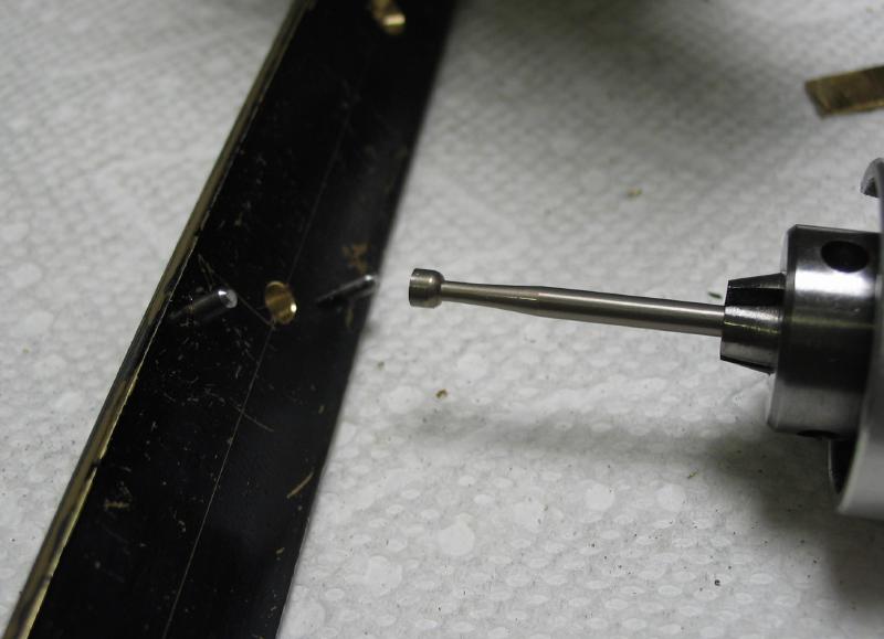
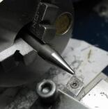
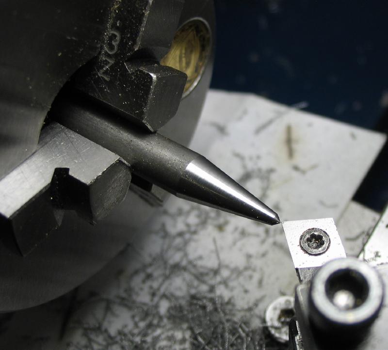
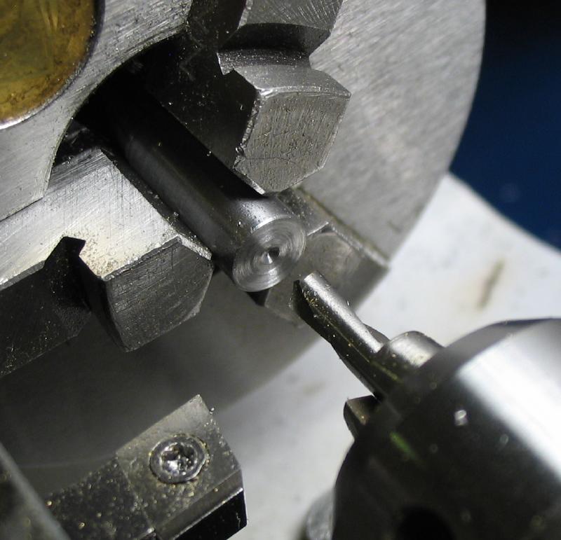
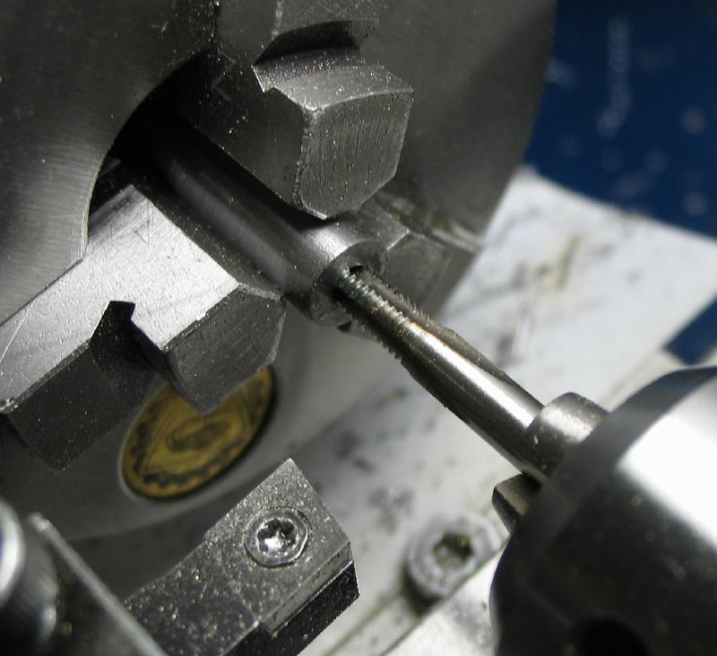
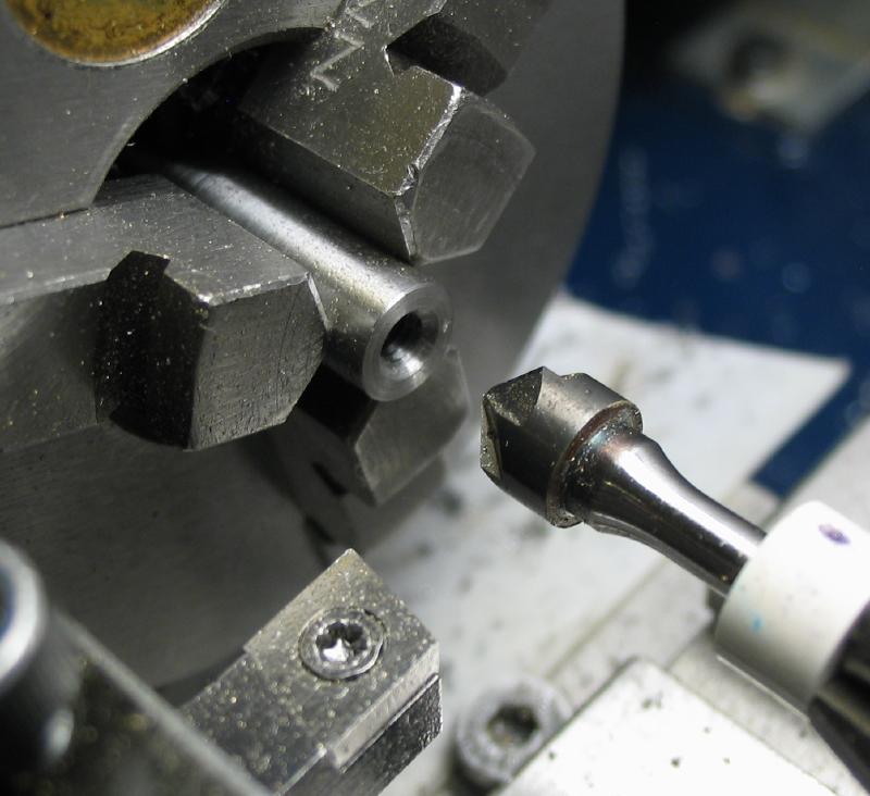
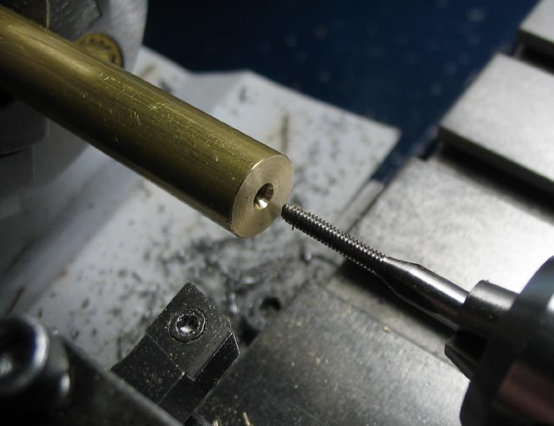
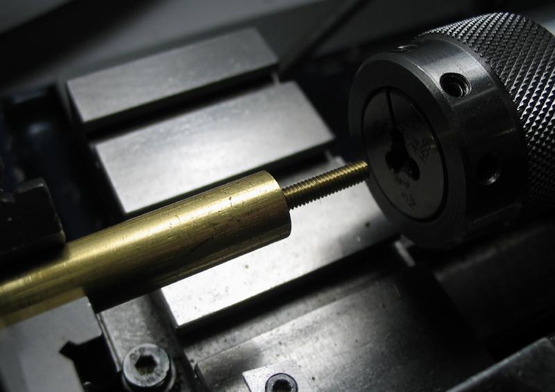
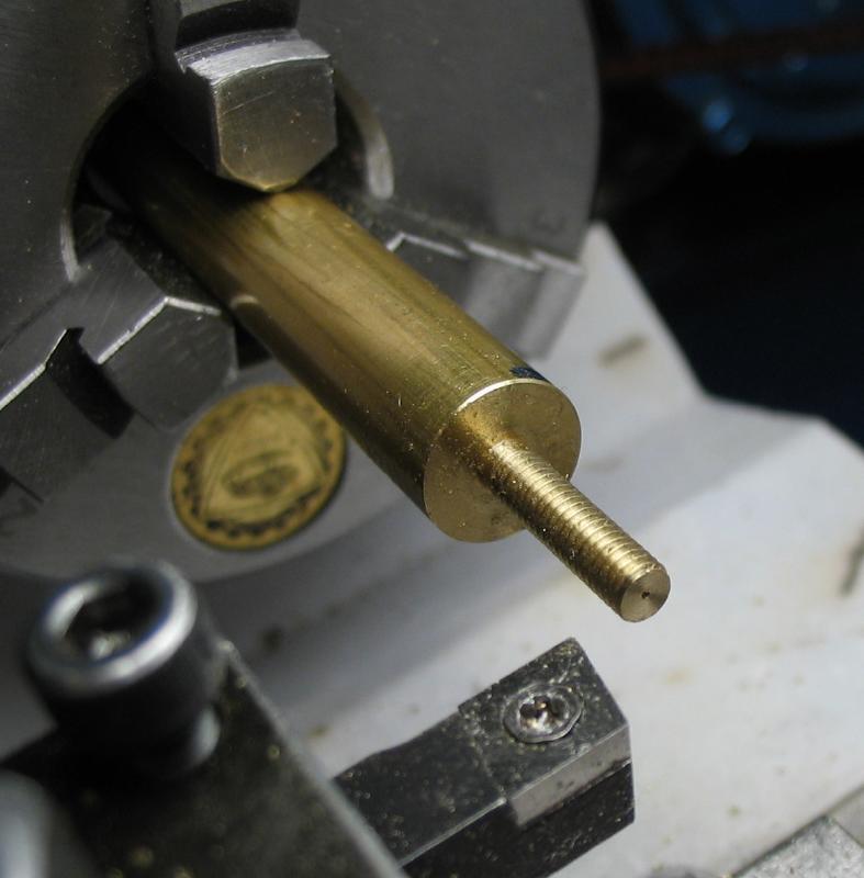
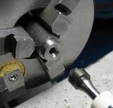
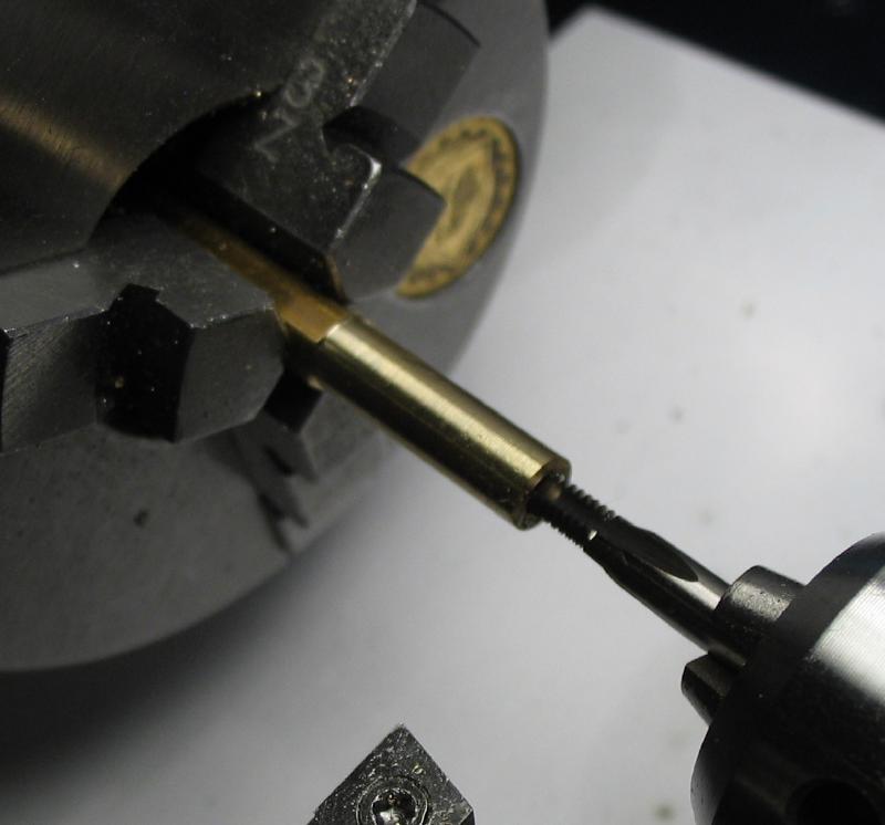
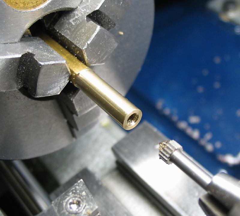
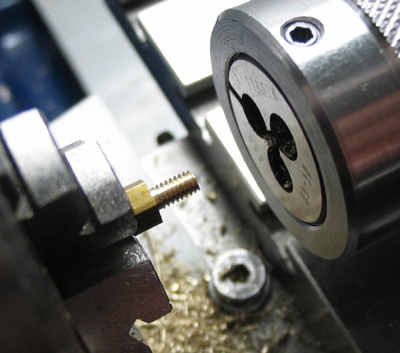
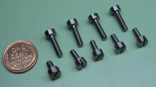
The pillar positions on the mainplates were laid out earlier and drilled to clear the pillar screws. Mr. Wilding describes using stock screws for this project that are in British Association thread sizes. I used the closest size taps and dies available, however, some of the sizes I am using do not have great variety of stock screws available, so I will need to make most or all the screws for this timer. Below are the various steps employed for making the pillar screws. The same method will serve for making other screws for steps further below. The advantage of making screws is that they can be made to whatever specifications one desires. The thread length is turned and a parting tool used to relieve the diameter next to the head since my threading die has a fairly deep taper and will not thread close to the screw head. The threads are cut using the tailstock dieholder and the tip rounded with a cup bur. The screw is then parted off at the desired head length. The work is reversed into a collet and the top face turned and the corners chamfered. With the headstock locked, a slotting saw is used to form the slot.
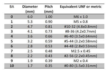
The pillar screws are #5-44 instead of BA 5. The table below lists BA thread numbers and their diameter and pitch and the closest equivalent threads that are available here, i.e. metric and Unified (UNF). It just so happens that BA #5 and UNF #5 are about the same, the two systems' numbers do not otherwise correlate.
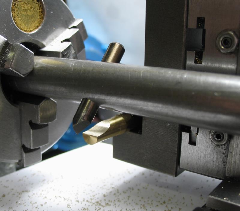
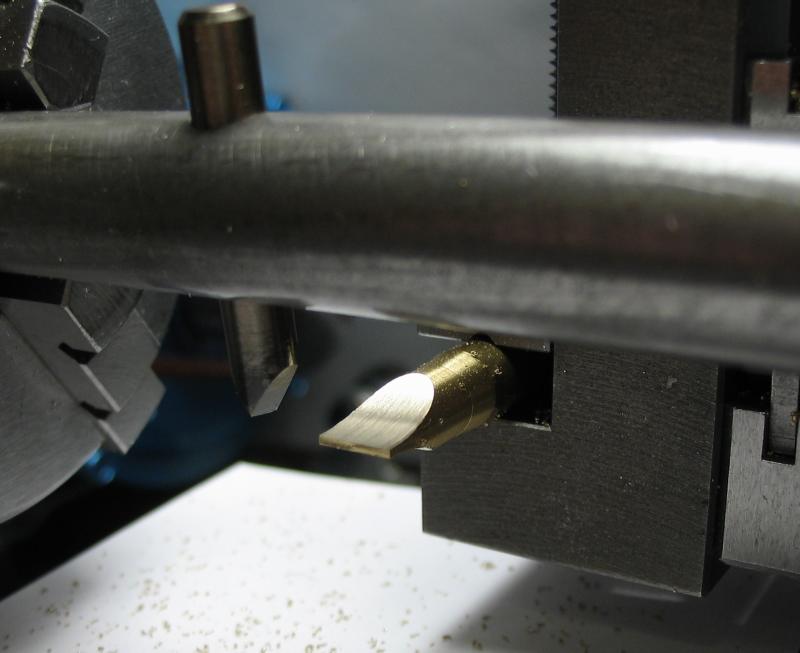
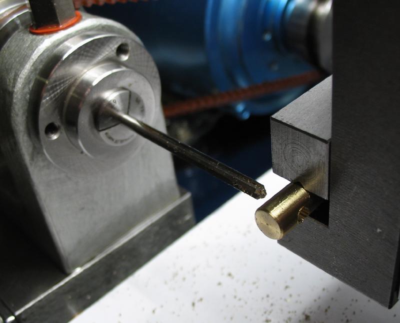
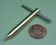
A dedicated driver was made to match the slots of the screws. It is made from 1/4" brass rod, that was reduced in diameter slightly and the blade formed with a fly cutter. A cross hole was drilled, reamed and fit with a short length of drill rod. I planned to use Loctite, but the rod was a very tight fit.
Pillars
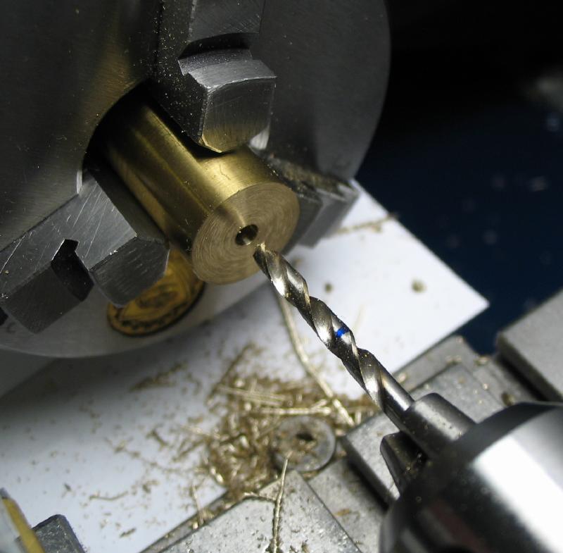
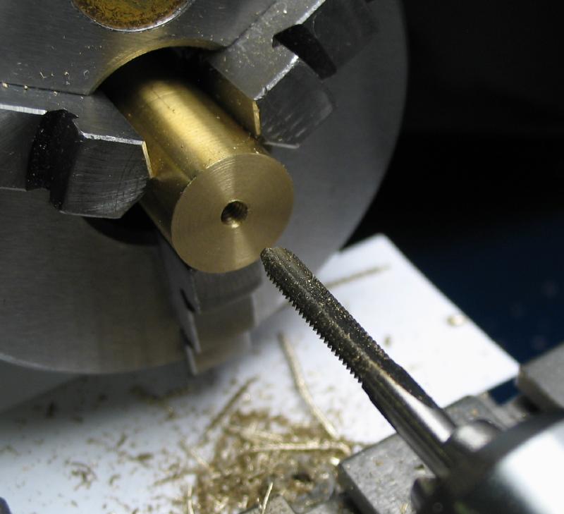
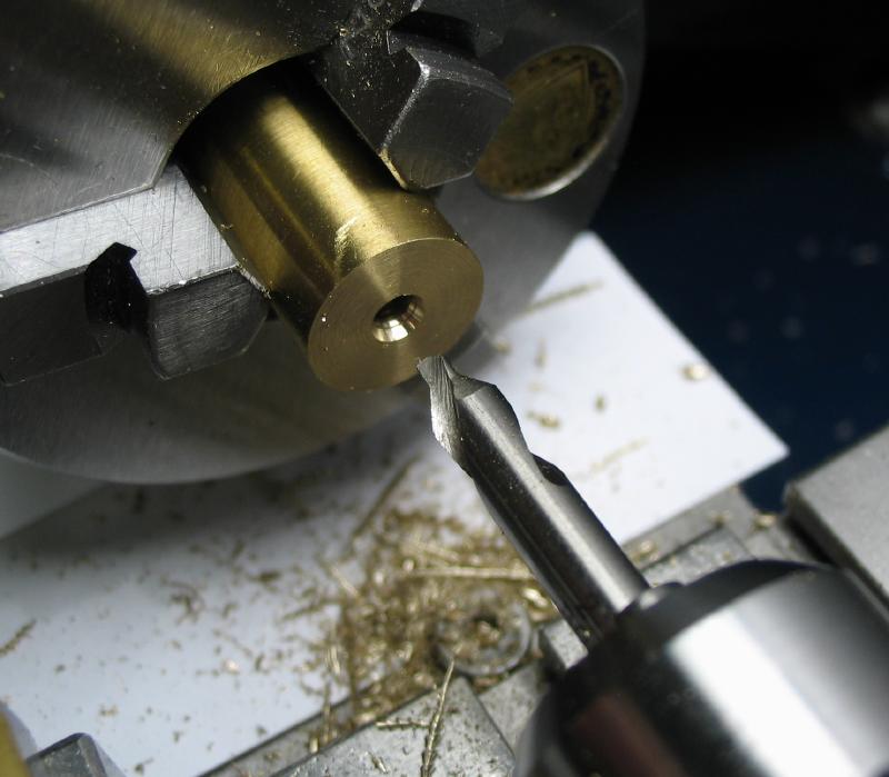
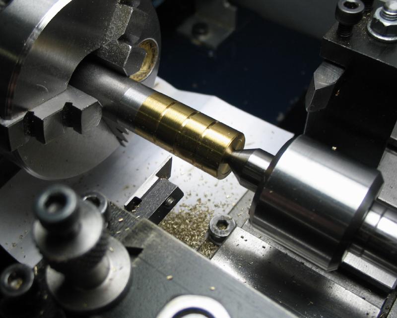
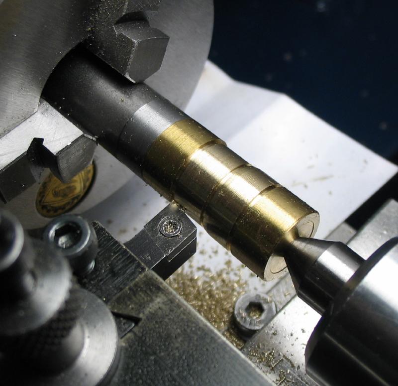
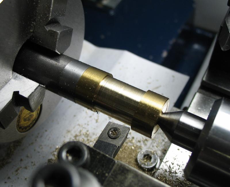
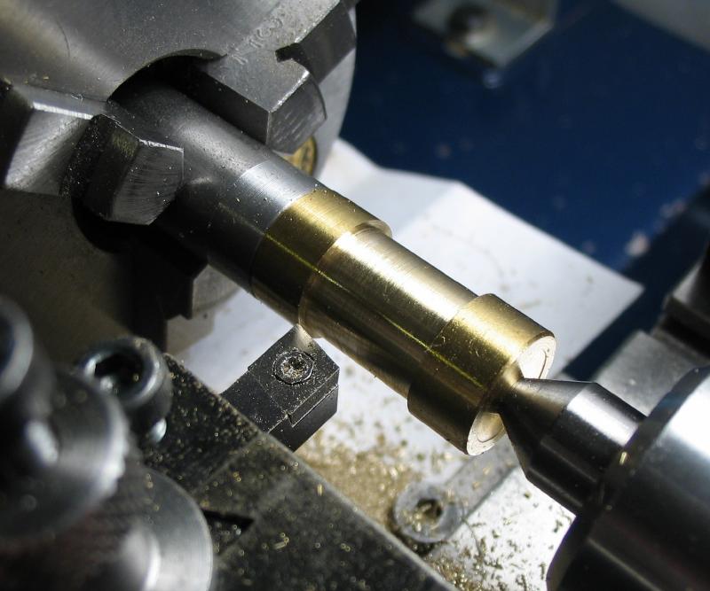
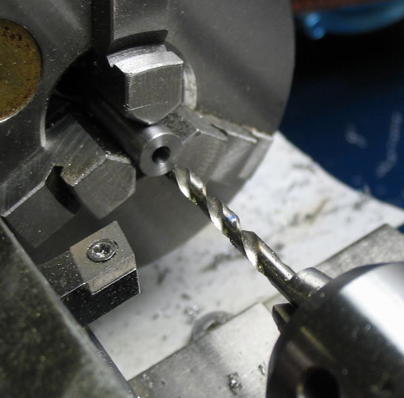
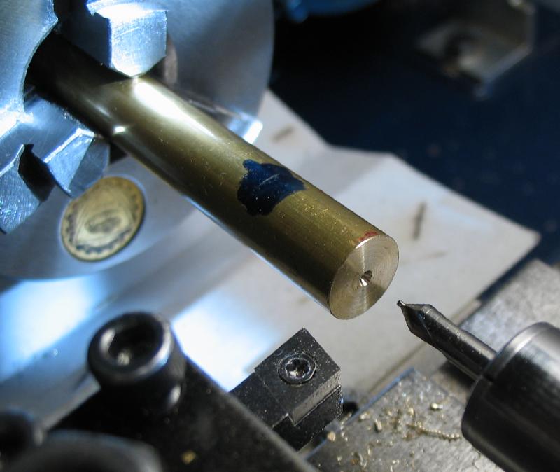
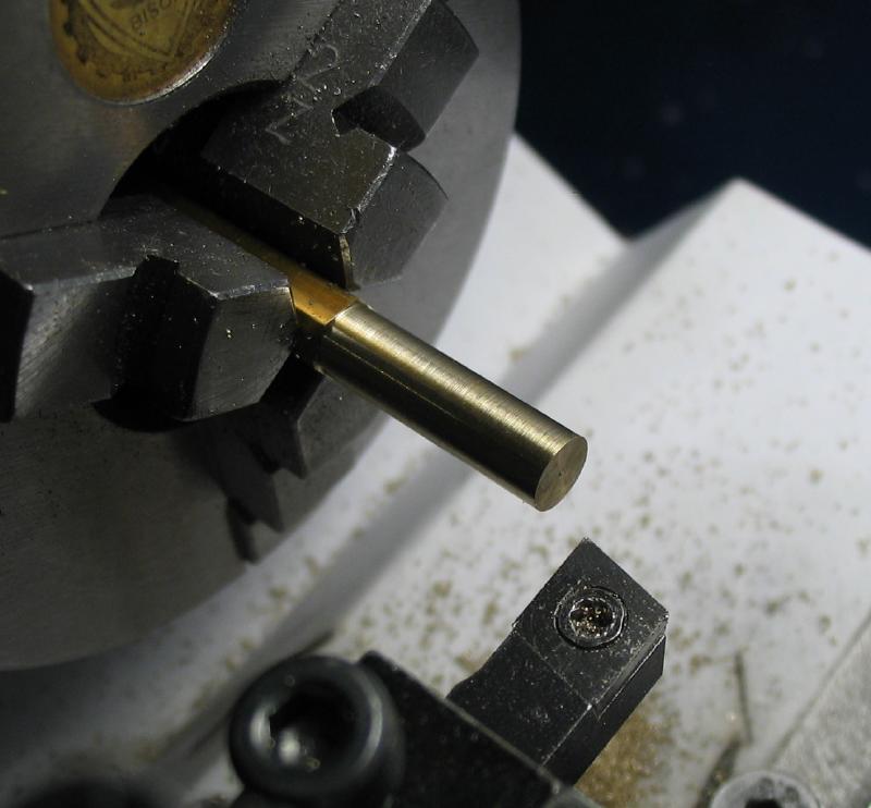
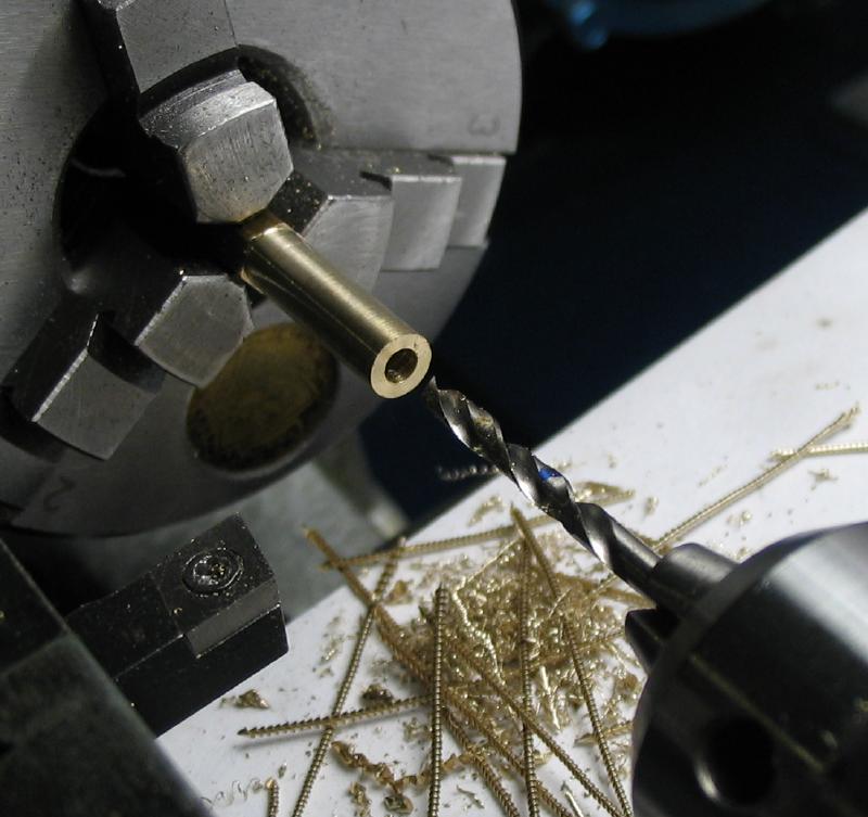
The main plates are separated by two pillars that were made from brass rod. The rods are drilled and tapped on both ends and a center drill used to form a small cone for tailstock support. Each face was counterbored so that the pillar will seat on the outer diameter of the face.
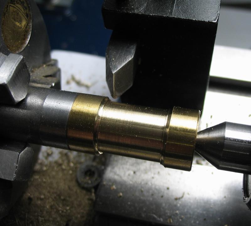
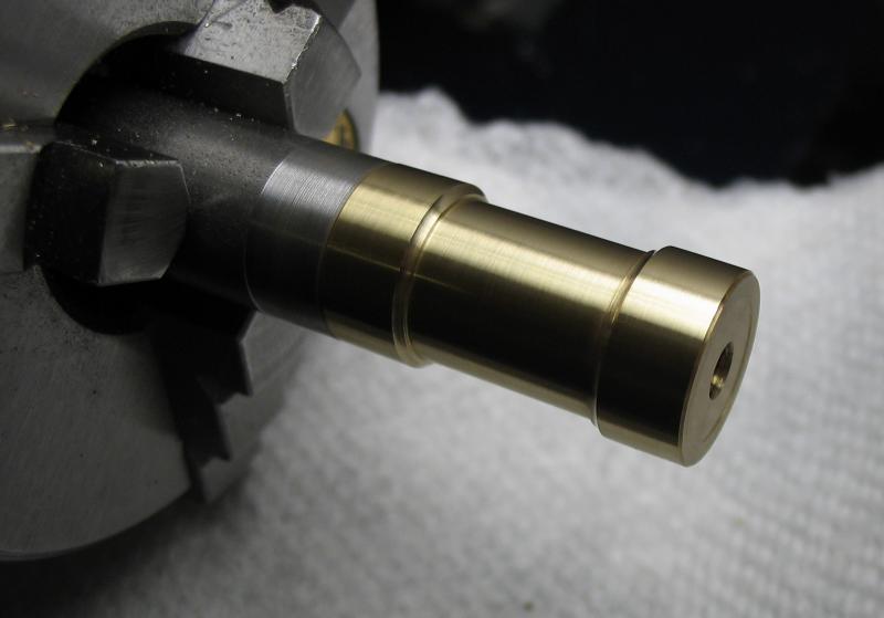
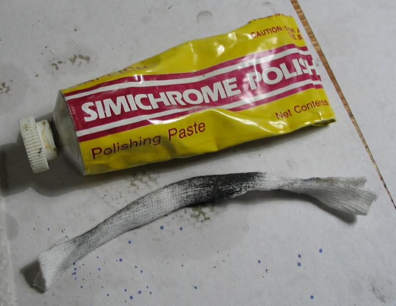
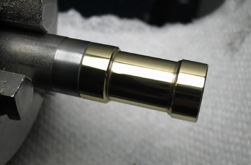
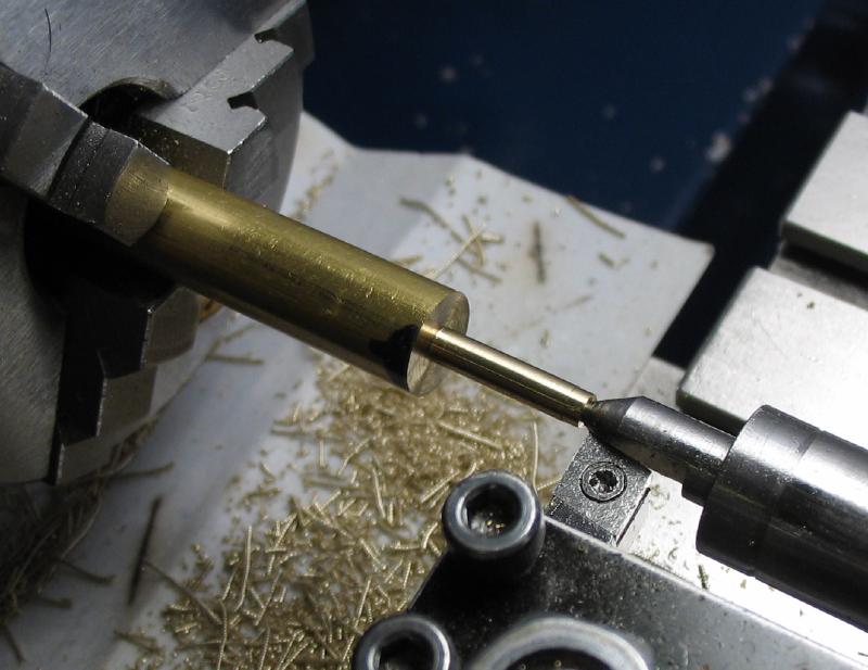
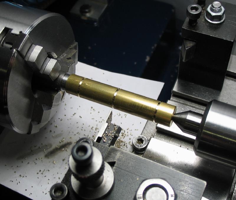
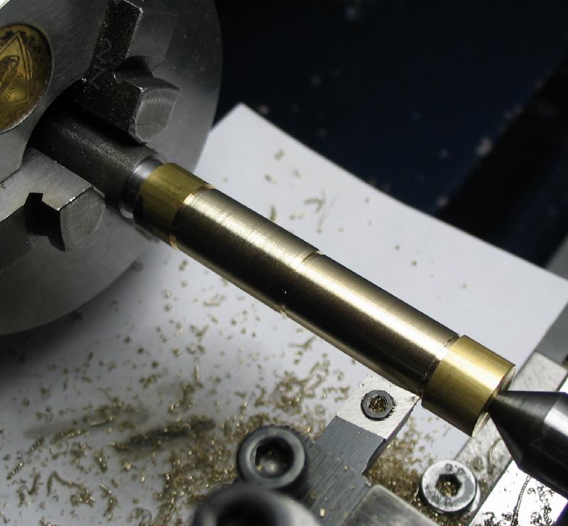
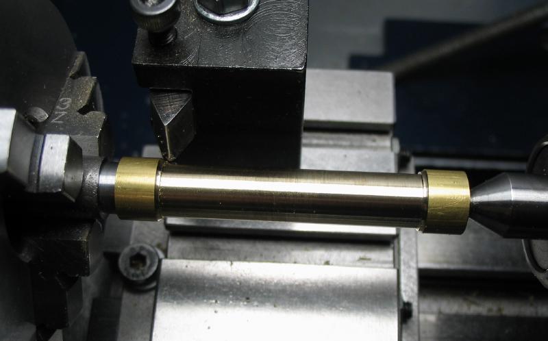
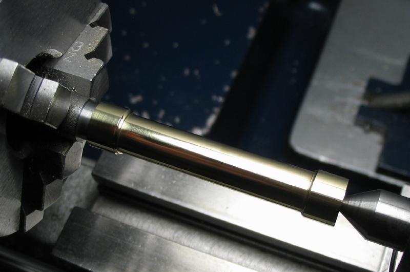
An arbor for holding the pillars for the finishing steps was made from steel rod that was turned and threaded to match the pillar and the rotating center used for support. The middle portion of the pillar is reduced in diameter using the parting tool to establish limits and then turned away using left and right-hand tools, and the corners then relieved with a round nose bit that was setup in the back tool post. Mr. Wilding demonstrates this all carried out with one tool bit, which I suppose work just as well... The finish was improved with emery sticks of various grits (400 to 3000) and ending with Simichrome paste on a piece of cotton rag.
Cross strut
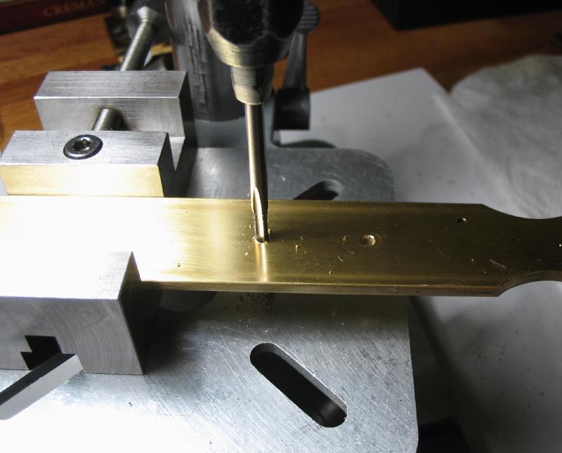
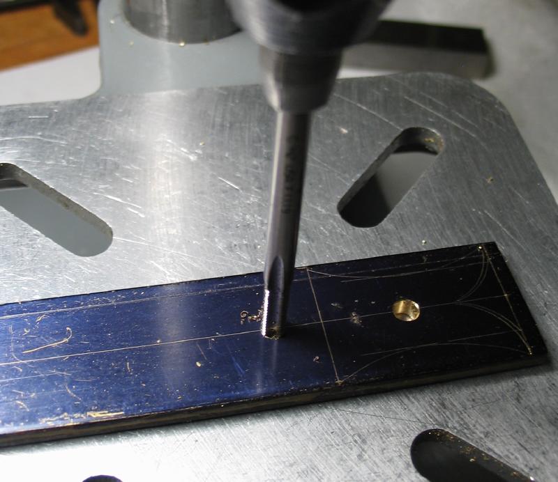
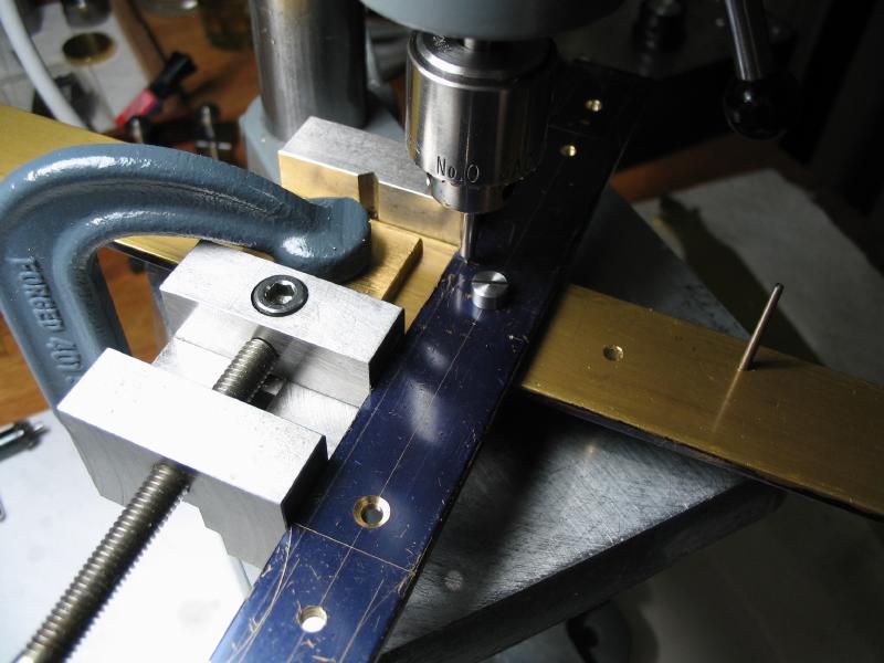
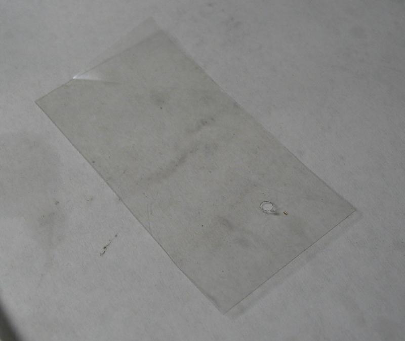
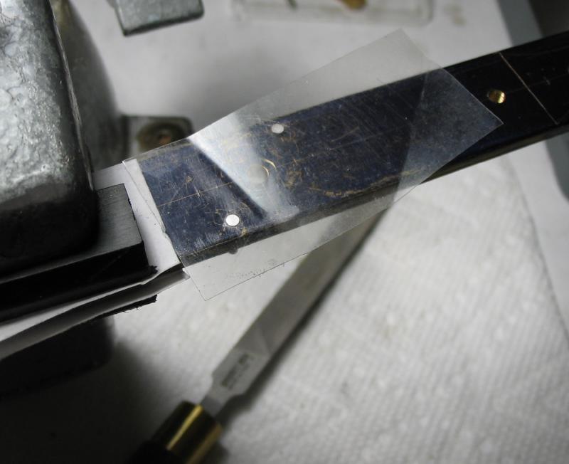
The location for the cross strut screw on the back plate was marked out and the main plates are registered together and the location drilled through for then tapping #5-44 in both. A screw was made to secure the cross strut to the back plate, and it was machined as above but to a shorter length. The other positions on the strut were drilled and tapped or countersunk as required. The strut will bear the dial pillars, cleats, weight hook, and alarm bracket. The strut is secured to the back plate with its screw and aligned with a square. The location for two register pins are drilled through, and reamed for taper pins. I am using a #5/0 pin reamer and matching pins. They are fit in the same manner as for the main plates above, however, these pins are permanent, so the excess is sawed off and filed smooth. A piece of thin plastic film with a small hole punched to fit over the pin was used to protect the surface of the brass from the file. Mr. Wilding demonstrates this using photographic film, but not having any of that laying about, I used overhead projector transparency film, if the reader remembers what either of those are. The remaining decoration of the strut was then sawed out and filed to shape. The filing machine was utilized for some of the coarse removal (my sawing accuracy was fairly poor), and then finished with needle files as above with the front plate. The surface finishes were improved with emery paper on a half section of a wine bottle cork.
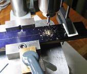
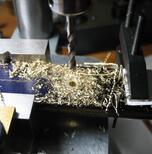
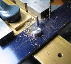
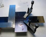
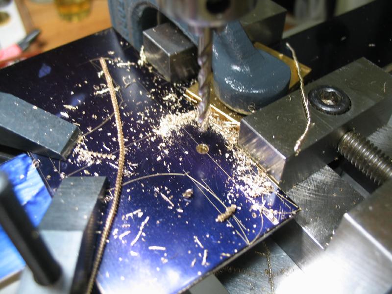
Drilling and tapping the mainplates, the back plate will receive the cross strut
Cleats
The outer two holes on the cross strut are for the dial pillars and cleats. The dial pillars have a threaded shaft and the cleats act as nuts to secure them in place. The cleats were made from steel rod. The point was turned with 10 degree taper, and with about 1mm remaining, the tip turned with a 45 degree taper. The 90 degree point should be more durable. The work is parted off, reversed and turned to the correct length. The reverse end is drilled and tapped to match the stud on the dial pillars. The hole was countersunk to be sure it will tighten securely in use.
Dial Pillars
The dial pillars were made from 3/8 brass rod. One end was faced and the corner chamfered slightly, as usual, and drilled and tapped #2-56 (substitute for BA 8). The hole was countersunk with a 60 degree center drill since tailstock support will be employed later. The work was reversed in the chuck and center drilled for tailstock support. This end was turned and threaded #5-44 and the work is brought to the correct length at the same time. There was an excess of length, which results in the threaded portion needing to be shortened, but this is an advantage since the center cone can be turned away.
Both pillars were made up to this point and then a threaded mandrel was made on lathe that the pillar can be screwed into and held for turning the body of the pillar. This was carried out in the same manner as for the mainplate pillars where a waisted region is turned and the finish improved with emery sticks.
Bridges
The front and back bridges are made from 1/16" brass plate. The design is laid out and the pivot position drilled undersized. The front and back mainplates are registered together and drilled through with the same bit. The front and rear plate and bridge combinations are then aligned with the drill bit and the pillar positions formed. The positions are drilled for tapping #6-40 and the holes in the bridges opened to clear the threads.
The rear bridge is also drilled for the hanging finished timer on a post. With the various positions all drilled, the bridges can then be sawed and filed to final shapes.
Bridge Pillars
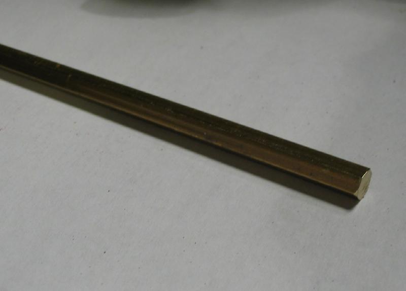
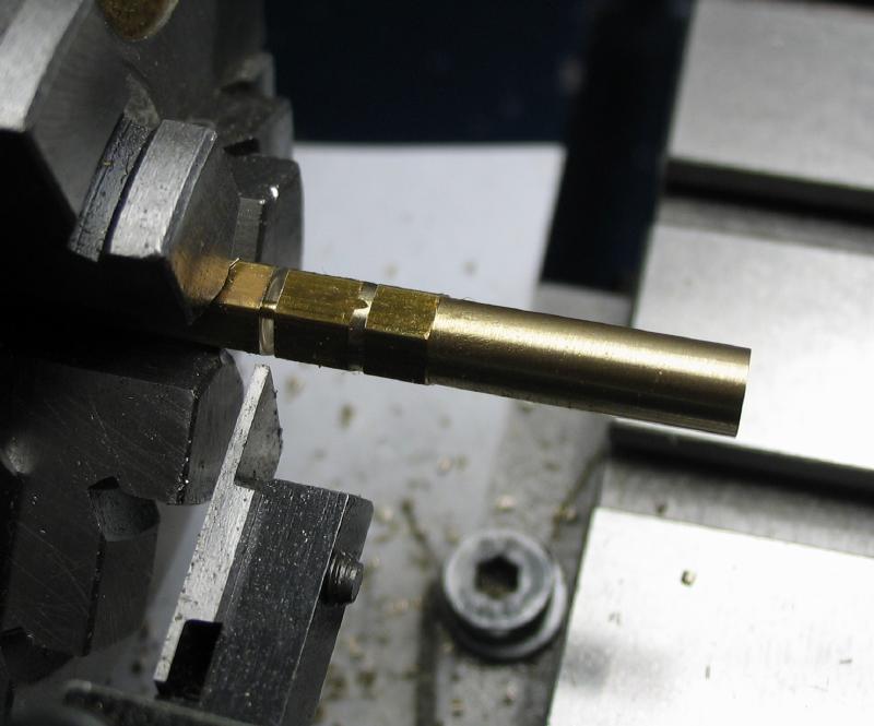
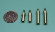
The pillars for the front and rear bridges were made from brass hex rod. They are turned round for most of the length, drilled and tapped, and hole countersunk slightly. The reverse ends are then turned and threaded to attach to the main plate. Two pairs of screws needed to be made that are #4-48. The set of pillar, plate and strut screws are shown.
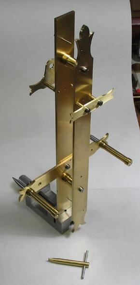
Assembly of the plates, bridges, pillars and strut.

