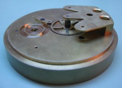
Making the Main Plate
The Dial Template
After beginning the construction of a few different components, I started thinking about the making of the main movement plate.
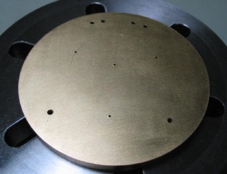
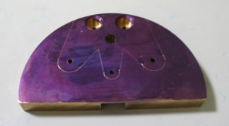
First a dial/movement template is constructed. This is a direct approach of doing this, I had already modeled the watch extensively in CAD software and therefore have a fairly good idea of many of the dimensions. However, keeping with Daniels method, a plate is made which first is drilled with the location of the center wheel and the fourth wheel, i.e. the minute hand and second hand positions, respectively. From these locations the positions and dimensions of the various other components can be scribed and their practical diameters found. This template is then used to transfer these locations to the mainplate of the movement, which will be seen later.
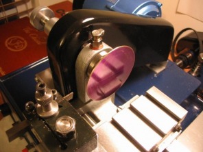
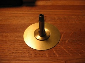
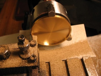
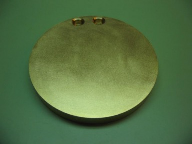
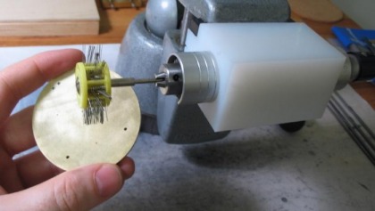
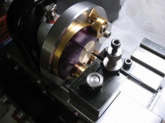
I started with a sheet of 1/32nd brass plate and scribed a 58mm circle, and cut it out with a piercing saw. Attached the plate to a superglue arbor and machined it to exactly 58mm in diameter.
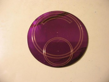
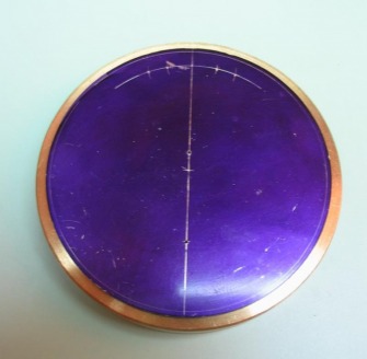
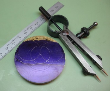
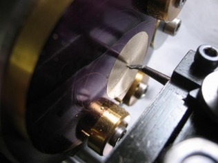
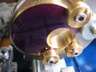
After lapping the disc fairly flat and recoating in layout blue, I began scribing the dial layout onto the plate. The "center" and seconds holes are drilled 0.5mm.
Mainplate
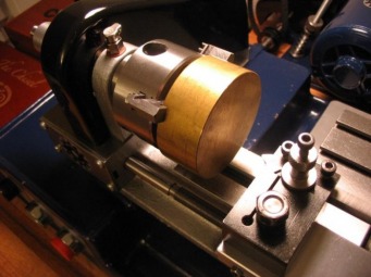
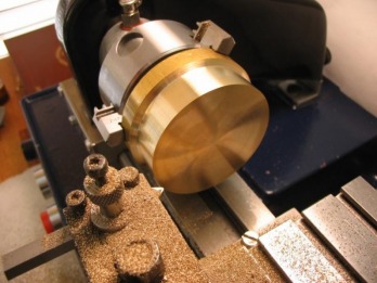
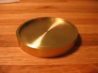
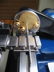
The plate will be 58mm in diameter and 3.6mm thick. A brass disc as close as possible to these dimensions would be ideal. The best I could find was a length of 2 ½" brass rod (type 360). It could have been sawed into smaller lengths, but I intend to machine as is. You may not think it to be that large, but this is a heavy piece of metal when considering the machine that I will need to turn it on. With the chuck jaws reversed, there is only a few millimeters of clearance over the lathe bed, and the motor stalls briefly when switching it on.
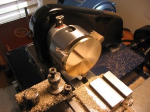
Since I have about an inch of brass to work with, my plan is to make the main plate (about 4mm), the disc for making the barrel bridge (6.1mm), and then make a movement rest out of the remainder. I simply faced the disc flat and turned a length of about 15mm down to the required 58mm.
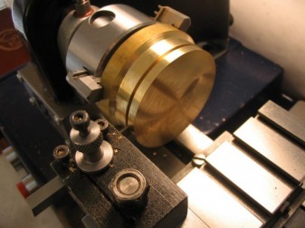
I can use the parting tool to make a start on the separation of the disc that will become the main plate, but for the most part it will need to be hack-sawed and then refaced to the proper thickness.
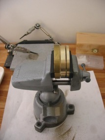
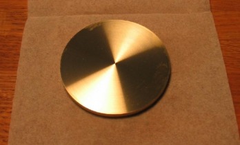
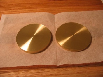
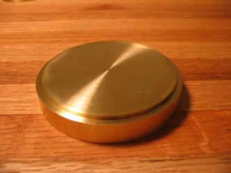
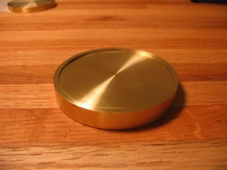
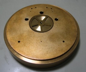
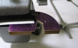
So after making piles of swarf and a sore tricep from hacksawing, you can see a shiny disc that will become the mainplate of this watch. The second disc, will form the barrel bridge (technically, I think it is a cock rather than a bridge, but I'd rather say bridge...). It may seem wasteful, but I imagine this is the historical method for making this part, and has the advantage of being easily changed to make a ¾ plate or a ½ plate, or whatever shape bridge/cock desired. The O.D. of 56mm will be useful in the final shape, and the extra material also aids in the machining steps.
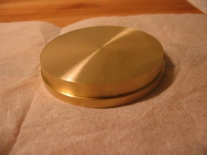
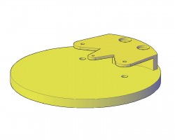
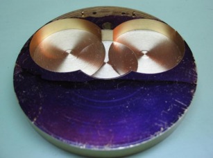
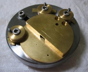
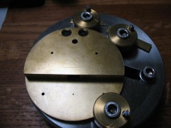
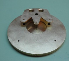
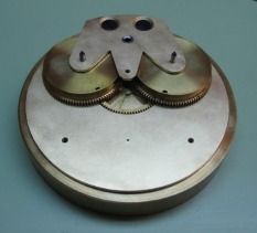
It is made the same way as the mainplate disc, so I won't go into the details again. While making this disc I followed figure 531 which specifies a thickness of 6.1mm, but if you follow the text on making the barrel bridge, Daniels specifies to make a disc of 6.4mm thickness. Having spent a number of hours making a 6.1mm thick disc, and not presently seeing a need for 6.4mm, I will continue and only go back and remake it if need be. Shown is a photo of the bridge disc on top of the main plate, from the AutoCAD drawing you can get the idea of where it is leading to, and as mentioned, much of the second disc will be waste.
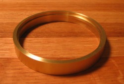
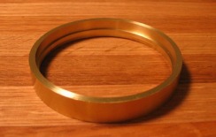
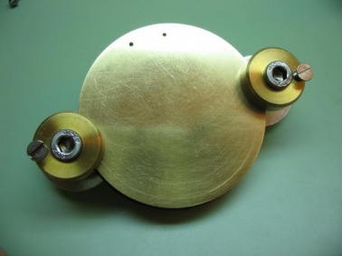
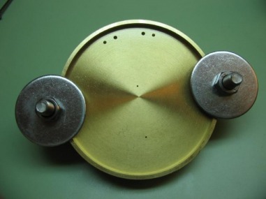
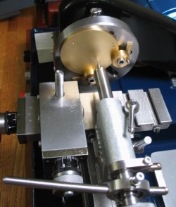
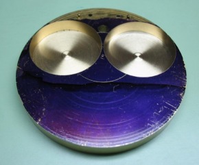
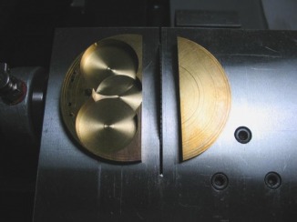
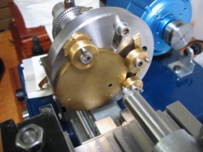
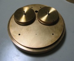
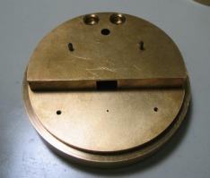
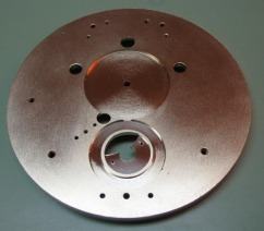
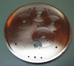
Using the remaining brass, I made a movement rest for later on, when I will be actually working on the movement. It has a snug fit with the mainplate so that it rests just above the holder and also has clearance below, this way the various components (barrels, bridge, tourbillon, etc.) will be contained within the holder while working on the dial side of the mainplate. The holder has a double function, where the mainplate will fit snugly within the holder so that it can act as the template marking jig described under "Making the Frame" and figure 534 of "Watchmaking." Shown is the holder in the two respective positions, first with a 2.5mm depth recess and the reverse side with a 5mm recess. The internal ring is 56mm Ø and 2mm wide.
Here are a few photos to try and show it in use, first the mainplate in place as it would be while working on it, and second with the mainplate in the reverse side for transferring the dial template. Below these is a photo with the barrel bridge disc in place to show how the component would be safety contained in the holder while working on the dial side of the mainplate.
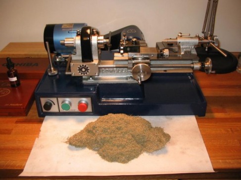
The pile of brass swarf from making these pieces!
After facing, the disc can now receive a recess on the dial side. The recess will provide the space required for all of the under-the-dial components, which, for this watch is many. Daniels' style (see below) is such that the watch has a tasteful, subdued appearance, and not jumbled with various wheels, bridges, springs, etc, so much of the work is hidden under the dial, including the winding work and the third wheel, which typically can be found on the top side. I am leaving this recess about 0.3mm deeper than proscribed in 'Watchmaking,' I thought of this while facing it down, and stopped at 3.9mm instead of 3.6mm. The plate thickness for the various components will remain the same, but I decided to leave a little extra recess space for the motion work. I will discuss in much more detail when the time comes, but I have not yet decided on the motion work, i.e. whether to continue with emulating Daniels No.4 with retrograde hour work, or to use simple motion work. Daniels gives an example of how to construct the retrograde work, but does not go into much detail, so I will be designing much the final dimensions. Therefore any extra space for the motion work could come in handy later on, and can always be trimmed down later on as well.
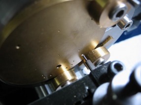
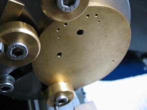
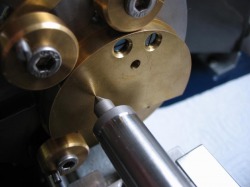
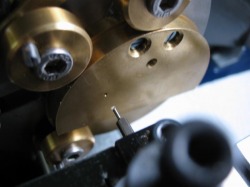
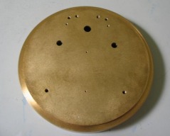
The 'center' and seconds positions can be transferred from the dial template, or laid out from a drawing. I wasn't completely satisfied with the drilling of the template, and decided to layout the positions directly. So much for all that preparation! The plate is coated in Dykem blue, and the positions scribed from the true center with a compass. The positions are center punched and the plate mounted on the faceplate and drilled 0.5mm. A center line is scribed, intersecting the two positions. From this line and from the true center of the mainplate, the positions for the barrel bridge screws and steady pins can be marked, and center punched. I followed the dimensions and layout as depicted in figure 535 of "Watchmaking," but I think any measurements have to be converted to scale). After drilling the screw positions and comparing to various photos of Daniels' watches, the relative locations are not quite the same. The screw positions should be brought towards the center by about 1 mm (as compared to the drawing), and the steady pins could kept on the current arc, but looking at some of Daniels watches, he apparently used three steady pins (one in the center).
Barrel Bridge
The bridge is attached to the mainplate by two screws, fit into recesses. The disc which is to become the bridge is clamped to the mainplate. I had scribed the 56mm diameter onto the mainplate as a guide for positioning the disc. This sandwich could then be drilled (1.2 mm) for the screws. This is the tapping drill diameter. Daniels recommends drilling 0.95 mm for 1mm brass steady pins, However, I did not have any 1mm brass rod and instead used some rod measuring 1.15 mm (which I suspect is wire gauge no. 17) that was in my stock drawer. I therefore drilled the holes 1.10 mm.
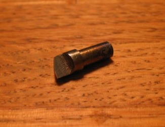
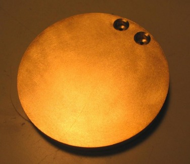
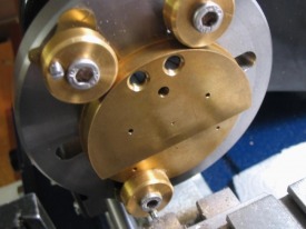
The screw holes were enlarged in the bridge disc to clear the 1.50 mm screws, and the holes in the mainplate were tapped 1.50 mm. The screwhead recesses were cut using a D-bit, which was made from 5mm O-1 drill rod (the diameter of the screw head), turned a shank (4mm) to fit a collet in the tailstock, and filed the cutting diameter in half and filed clearances on the sides and face. It was hardened in oil and the tip tempered to a straw color. Afterwards it was sharpened on a fine oilstone. The bridge is mounted on the faceplate and drilled for clearance of the screw thread (1.5mm) and the drill swapped for the D-bit and bored to depth, and finally countersunk with a 8.5mm round bur. Mounting this disc, that much off center, was difficult to put in balance, and part of the disc was off the edge of the faceplate . This step would have been much more easily performed on a larger lathe.
A couple poor photos of the screw recesses bored and countersunk.
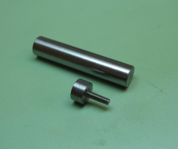
The bridge screws have a 1.5mm thread diameter and a relatively thick cheesehead. They are turned from 5mm O-1 drill rod, threaded with a die, and slotted with a Vallorbe No. 6 screw-head file.
The screws are then hardened in oil, and tempered to blue. Getting an even blue color was not as easy as I though it would be. This was the result after the third try, each time the screws have to be rehardened and repolished before tempering. Since they are likely to get scratched up during the numerous assemblies and disassemblies that will take place while making the remainder of the watch, I will wait until the movement is closer to completion and go back and re-blue the screws.
I made a screwdriver specifically for these screws. See construction page.
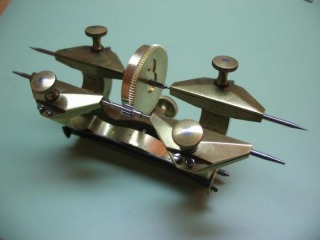
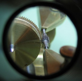
Machining the Barrel Bridge recesses begins by depthing the positions for the barrels. Daniels provides a detailed explanation of the practicalities of depthing a wheel to a pinion. This is accomplished with the depthing tool. This is my first attempt at using this tool and it seems to require some experience to obtain the best result. Some references even (such as Louis Levin) regard the use of the depthing tool as no longer an accurate method. However, for those making a watch or clock in the home shop, it seems to be the best way of going about it.
In short, one is looking for two points of contact. As a tooth-leaf pair are going out of contact a new pair should be coming into contact, this results in a smooth, almost effortless transmission of power. The engagement can be too deep or too shallow, and results in the common errors of engagement (as follows).
1) Drop - angle of engagement is too large after center line or deep and results in an acceleration relative to the pinion.
2) Binding - engagement before center line is too great or too shallow results in a reduction of power and could even stop the movement.
If the wheel (barrel) and pinion have been machined exactly to specifications, the correct depth is determined from standard formulas based on the cutters used. Going back to their respective pages, you will find the pitch circle diameters are 24mm and 3mm for the barrel and center pinion, respectively. This would result in a 13.5mm theoretical depth. The depth tool was setup for this, and it does, indeed result in a fairly good engagement.
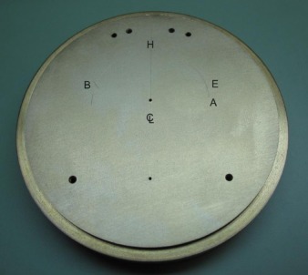
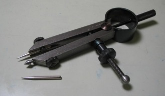
Once a smooth engagement has been found, the radius can then be scribed onto the mainplate. The barrel and center pinion are removed from the tool, and the runners are set to be level (in order to scribe). Since the radius is to be scribed from the already drilled 'center' position, the trumpet runner is needed. An arc is scribed onto the mainplate (arc A), which indicates that the barrels could be planted anywhere on that arc and would be in engagement with the center pinion. Daniels' method assumes confidence that both barrel have been machined identically, one should double check that the depthing is the same for both barrels and if not then scribe separate arcs and identify which arc belongs to which barrel from then on. At a radius equal to the barrel plus 0.5mm and perpendicular to the centerline of the mainplate; a mark is made on arc A. This point (E) is the position for the first barrel. With the compass set to the same distance, a mark is made from (E) to the centerline (H). The position for the other barrel (B) is found from (H) to the arc (A). In the photo I added labels as above, the scribe marks may be difficult to see.
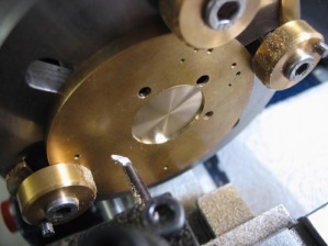
The positions are found with a prick punch and then drilled 0.6mm. Drilling was carried out on the lathe. The lathe is versatile in that drilling and light milling can be performed, however, a small high precision drill press would have expedited this process significantly.
Drilling procedure:
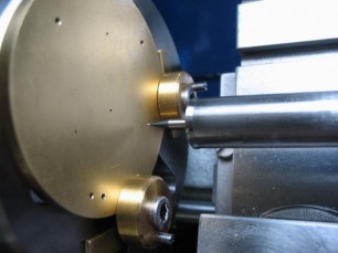
I centered the mainplate on the faceplate to one of the barrel positions.
The position was assured by lightly chamfering with a very small setting burr in the tailstock (this provided a start for the drill).
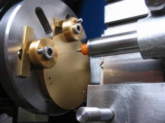
The hole was drilled using a 0.60mm carbide drill.
Drilling complete.
The scribe marks are to be removed at this stage. To do this I brushed the surface of the plate using a 0.20mm wire texturing wheel. These are made for putting a grained or frosted finish on jewelry or any soft metal. The brush can be held in the Foredom flexshaft or some other means (the lathe for instance) and worked in various angles to produce a pleasing appearance. This works out the scribe marks (if they were done lightly to begin with) and is also the ultimate finish that will be applied to the plate.
The barrel bridge plate is then secured to the mainplate and setup for drilling through each of the barrel holes and the center wheel hole to depth of 1mm into the barrel bridge. The procedure is the same as above.
The bridge is removed and circles scribed from the drillings which are 0.5mm greater in diameter than the measured diameters of the barrels and center wheel.
I am not sure if it would be helpful for anyone but myself, but I have started scanning my workshop notes and hand drawings. The link below are the determinations of barrel depths and notes during the process.
| Barrel Bridge measurement hand drawing | |
| File Size: | 202 kb |
| File Type: | |
The bridge recesses are bored out in a sequence of operations that will result in the bridge appearing to be of a uniform thickness, however, it is actually made to fit the lengths of the barrel arbor pivots. Daniels provides the details of this process, and it can be summarized as follows:
- Determine the first barrel's arbor length from shoulder to shoulder. (Easier said than done). Start working with the longer of the two.
- Bore the first (i.e deeper) recess using the faceplate. Determine full diameter minus 0.1mm [shown at this stage below.] and bore almost to full depth with the final cut to full diameter and depth. *note: the center drilling hole will have long disappeared.
- Make a further cut to full diameter and to an additional 0.05mm of depth, but leave a central boss diameter of 4.0 mm (this will be the pivot surface).
- Make note of this depth on the slide thimble (or reset to zero).
- Repeat the above process for the second barrel, and make the finishing cut to the first barrel's full depth (previously zeroed thimble). This is why one should start with the deeper length, however, they should not differ by that much.
- Machine the center wheel recess to the same full depth, the center pinion pivot shoulder is made to fit.
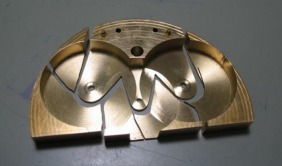
- As depicted in figure 539 of Watchmaking (First Edition), the bridge plate can be sawed down to a more convenient size, however leaving enough material to provide support during the drilling and boring that is to follow. The plate was sawed just below the barrel recesses. The work was done on the saw table attachment, which made a nice clean, square cut.
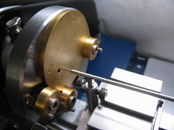
The mainplate is then secured to the face plate and centered onto one of the barrel positions using the wobble stick (see toolmaking section). The position is drilled to accept a boring tool and is then bored almost to the final diameter of the fingerpiece pivot. The bridge is secured to the mainplate (while still clamped to the faceplate - one must therefore be thinking ahead!) and the same procedure is repeated for the arbor pivot in the bridge. By doing it this way the positions will be upright.
Wobble stick used to set hole on center.
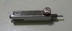
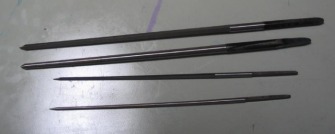
The hole is enlarged by drilling to allow a boring tool to enter. I am using a Micro100 brand boring tool, the cutting width is 0.045" (~1.1mm). The 1/8" shank on these is a bit small for the toolpost, so a holder was made from 1/4" mild steel square stock.
The hole is enlarged by boring to just under the final diameter (the fingerpiece pivot diameter). This was ensured by using a plug gauge made for the occasion.
With the plate still centered, the barrel bridge is attached and the tailstock used to make a center mark, which is then drilled and bored as before.
The boring completed.
After the pivot positions have been assured upright and bored undersize, Daniels does not provide further instruction. I assume he leaves it to the reader/maker to decide whether the pivot will be jewelled, bushed, or simply broached to fit the arbors. The center wheel turns relatively slowly (obviously, once per hour). The reader will be reminded that the visible barrel pivots do not rotate during running, only during winding. So the holes in the barrel itself would be sooner jewelled or bushed than the plate holes.
Daniels' early watches do not appear to be jeweled or bushed at the barrel or center wheel positions. English watchmakers, in general, seem to have been historically in preference to this, even going as far as not to jewel the third or fourth wheel positions. One argument is that the steel on brass interaction for slow moving components does not require a jewel bearing. This practice is commonly found in clocks (of course the argument is that clocks commonly require bushing to repair the worn pivots!). In the case of gilded movements, some have stated that the layer of gold on top of the work hardened brass hole (from smooth broaching), provides a sufficient bearing surface. From a practical standpoint, jewels are not available in the size required for these pivots, and should the pivot wear in time the position can be drilled and a bushing made to fit.
For more history on this topic, Glasglow's "Watch and Clockmaking":
"... there must have been a prejudice against jewelling watches at an early date, which has not yet quite disappeared, because of the tendency of certain sorts of stones to blacken the pivots when the watch has gone for some time and the oil turned viscid. However, there are no watches made now that have not at least the balance staff holes jewelled, and I do not think there are any watchmakers that will not admit that the holes of the escapement would in all cases be better for being jewelled; although I have heard
men argue that the third and fourth wheel holes of a watch would be better to be of good brass than to be jewelled. I am sure there are thousands of English watches that would have gone longer and cost less to repair, if they had been jewelled in a few more holes. The Swiss, on the other hand, jewel their very worst watches in as many holes as possible, and do it so badly that brass holes would in many cases be preferable. "
Cutting and smoothing broaches are used to enlarge the holes to fit the pivot.
This process is continued for the center wheel/pinion holes as well. First the recess in the mainplate is bored to a depth of 0.70mm (0.60 for the wheel and 0.10 of clearance).
The lower hole is enlarged and bored undersize (1.30mm). The barrel bridge is attached (again some foresight is needed when mounting the clamps), and the top hole is drilled and bored undersize (1.30mm).
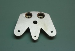
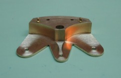
The shape of the bridge can be laid out at this point. To scribe the radii on the barrel bridge I made a trumpet point for the divider. The angles and shape are up to one's imagination, I am shamelessly copying Daniels....
The shape is cut out with the piercing saw, I used a 6/0 blade. I held the bridge in the Palmgren vise with nylon jaws and a slip of heavy paper to prevent further scratches. The Palmgren (now sold as Panavise) is positionable and this one was given to me many years ago, the previous owner made a heavy steel base for it so that it does not need to be bolted to the bench top and can be moved about. This is useful for sawing, as the vice can be rotated around to direct the cut.
At this point the center pinion can be finished, once the pinion is finished the holes can be broached to fit.
Some mainplate steps are detailed on other pages, including the fitting of the third wheel and its potences and the fitting of the fourth wheel. To keep this page up to date, the plate is shown here after these steps.
Some notes on 'Style'
From George Daniels' "Watchmaking"
" ... The Lepine calliper has greater appeal than the plated movement because all of the mechanism can be seen. Also the multiplicity of cocks and screws seems to indicate fastidious application and love of craftsmanship for its own sake. In the nineteenth century the Swiss makers were particularly concerned with the appearance of their watch movements. It is usually the case that when a watchmaker cannot make a technical advance he will divert attention by decorating his work. The Lepine calliper lends itself admirably to embellishment. But good practice dies hard and although the Swiss now lead technically, and micro-precision engineering has taken the place of watchmaking, the best Swiss makers continue to apply a jewel-like finish to their products.
The English makers also worked to a very high standard but did not make any obvious effort to intrigue the customer with a display of polished wheels and sparkling components. There would be no point in doing so. English hand finished watches were expensive and bought only by gentlemen. They, on the whole, were not interested in wheels and polish which were merely manifestations of trade, something which no gentleman would want to be thought to recognize. ... "
Decoration in watchmaking continues, of course, and may require very fine craftsmanship and special skill to execute successfully. In some instances what may be at first thought of as purely decoration, may in fact have a functional purpose, that has evolved in such a way that it is executed in a pleasing manner. The most common example is the blueing of screws, in some modern watches it is done chemically and purely for appearance, however, traditionally it is simply the result of tempering steel to its spring state and since it contrasts nicely with the color of the gilded plates, they are left blue. Speaking of gilding, Daniels' (as well as many others...) watch plates/bridges are machined from brass, and in the end the brass is gilded. In the modern superficial world, gold-plating would, at first, be thought of as a cheap alternative to using solid gold, however, brass is much more suitable for machining and is plated or gilded as a means of protecting the brass from oxidation and it is pleasing to look at as well. Another excellent example is engine turning, it would appear to be purely an exercise in ostentation, but it enhances the readability of dials by reflecting the light differently for the various dial sections.
