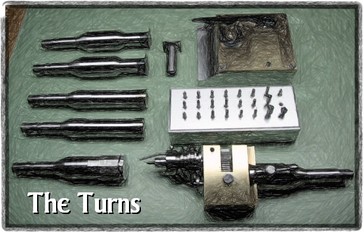
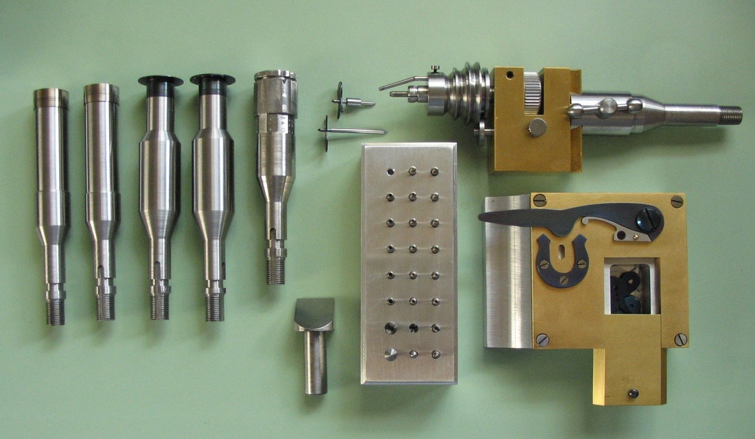
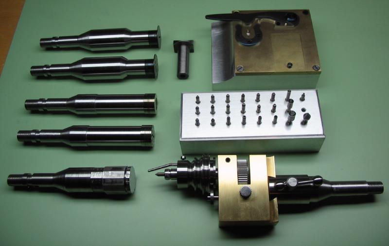
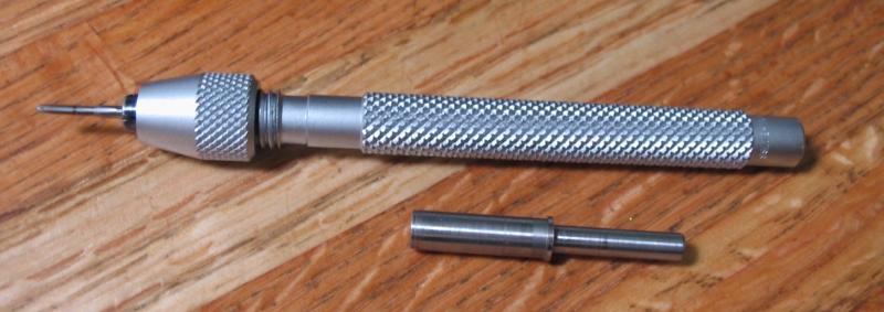
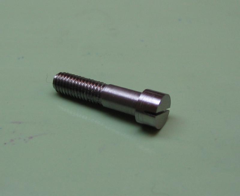
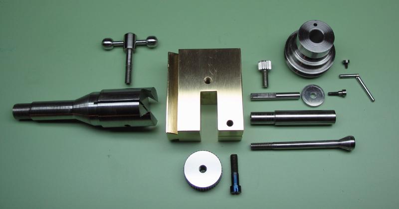
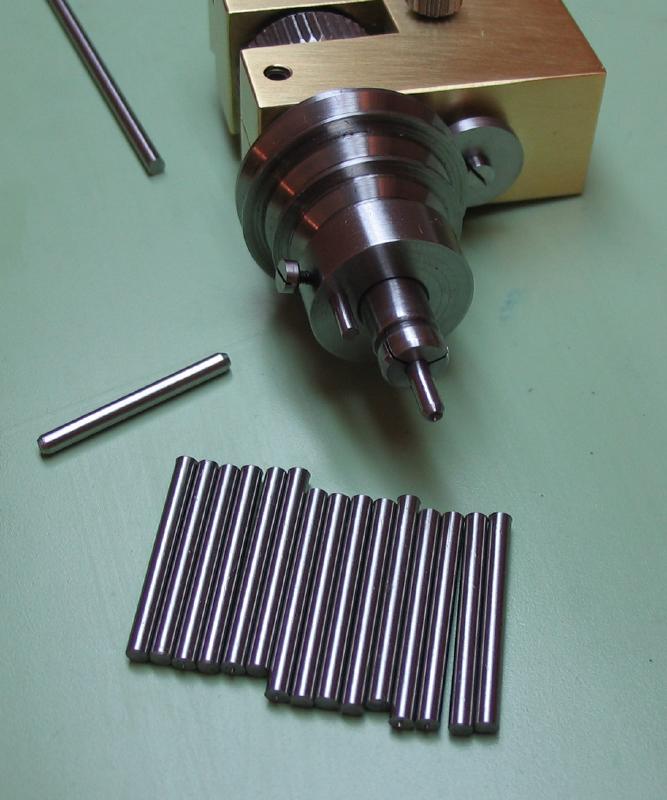
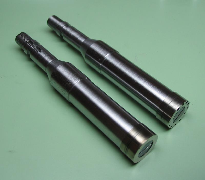
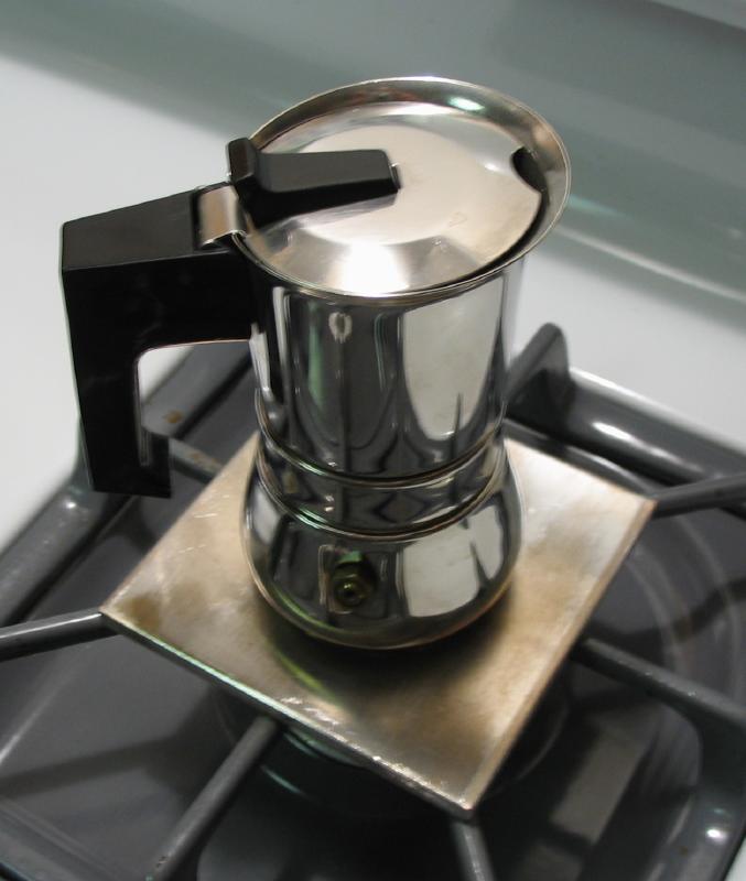
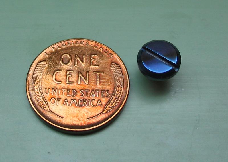
A Set of 'Turns'
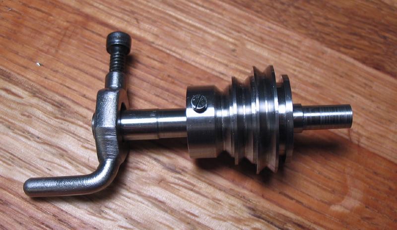
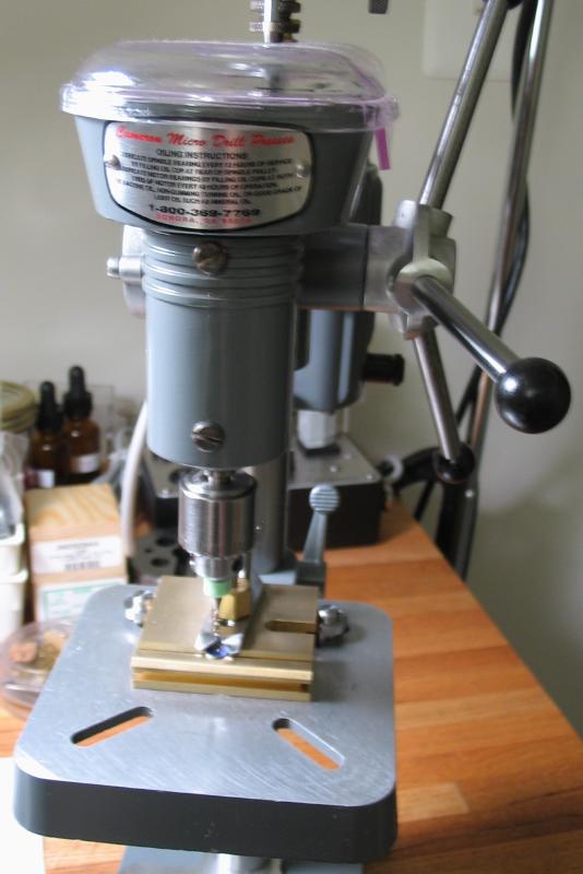
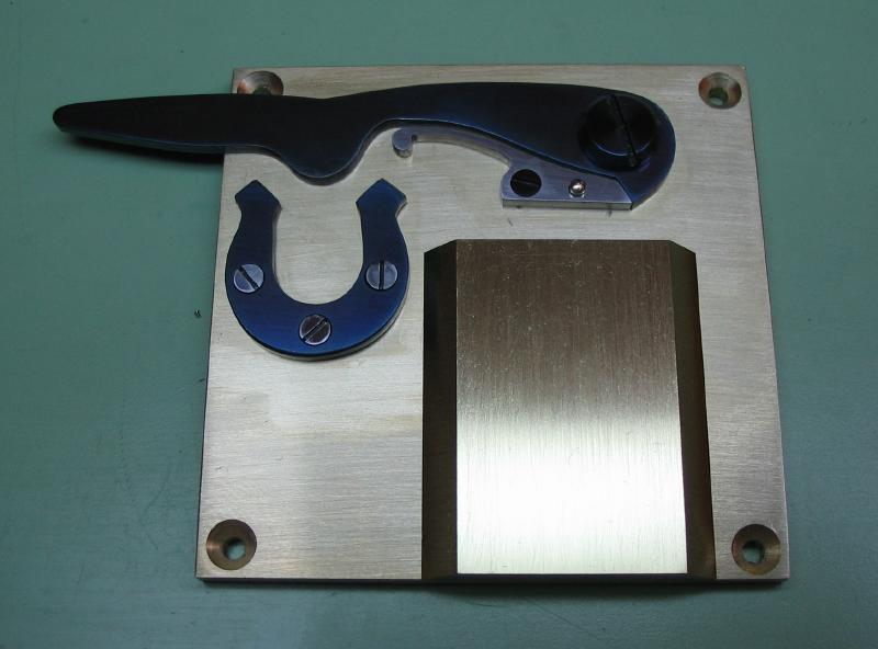
A traditional method of turning between centers is by hand driven power on a simplified lathe referred to as the 'turns' or 'dead center lathe.' Descriptions of turns and their use is discussed by various authors on watchmaking and repair. The advantage of using such a setup is better precision, especially when work needs to be removed from the lathe to test, and special guides for finishing small components, especially pivots. As I am getting on with some of the more delicate components of the watch described on this site, I decided that such a setup could be useful. Manufactured versions are available, such as the Horia-Steiner lathe, and attachments similar to what is described below can be found for many older watchmaker's lathes. I decided it would be a rather interesting project to make a set for use on the Cowells. There are quite a few components to be made, primarily divided in the headstock fixture and tailstock components.
The Horia-Steiner turns, as well as other makers, use an eccentric headstock. This allows the headstock to be aligned with the various tailstock pieces, which will be discussed later. The drive is by means of a pulley with drive pin, with the component mounted in a center (male or female) and a dog which is attached to the work. Power can be supplied by a slow speed electric motor or by use of a hand-held bow. The hand powered method is described by many authors to be preferred, as the progression of work is tangible through the feedback felt in the bow. Also, damage to the work is less likely. The details of its use and function will become more apparent when complete and demonstrated (this applies to myself as well, since I've never used one!).
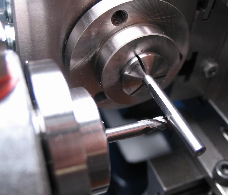
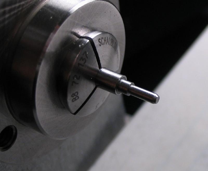
Since both the headstock and tailstock on the Cowells 90CW are accepting of the B-8 style 8mm collet, the respective pieces of the turns setup will make use of this.
A set of drawings are below, but many of the dimensions were worked out as things progressed and to utilize metal stock that was on hand as much as possible.
The Horia-Steiner turns, as well as other makers, use an eccentric headstock. This allows the headstock to be aligned with the various tailstock pieces, which will be discussed later. The drive is by means of a pulley with drive pin, with the component mounted in a center (male or female) and a dog which is attached to the work. Power can be supplied by a slow speed electric motor or by use of a hand-held bow. The hand powered method is described by many authors to be preferred, as the progression of work is tangible through the feedback felt in the bow. Also, damage to the work is less likely. The details of its use and function will become more apparent when complete and demonstrated (this applies to myself as well, since I've never used one!).
Since both the headstock and tailstock on the Cowells 90CW are accepting of the B-8 style 8mm collet, the respective pieces of the turns setup will make use of this.
A set of drawings are below, but many of the dimensions were worked out as things progressed and to utilize metal stock that was on hand as much as possible.
| Headstock Components |
| Tailstock Components |

|
|
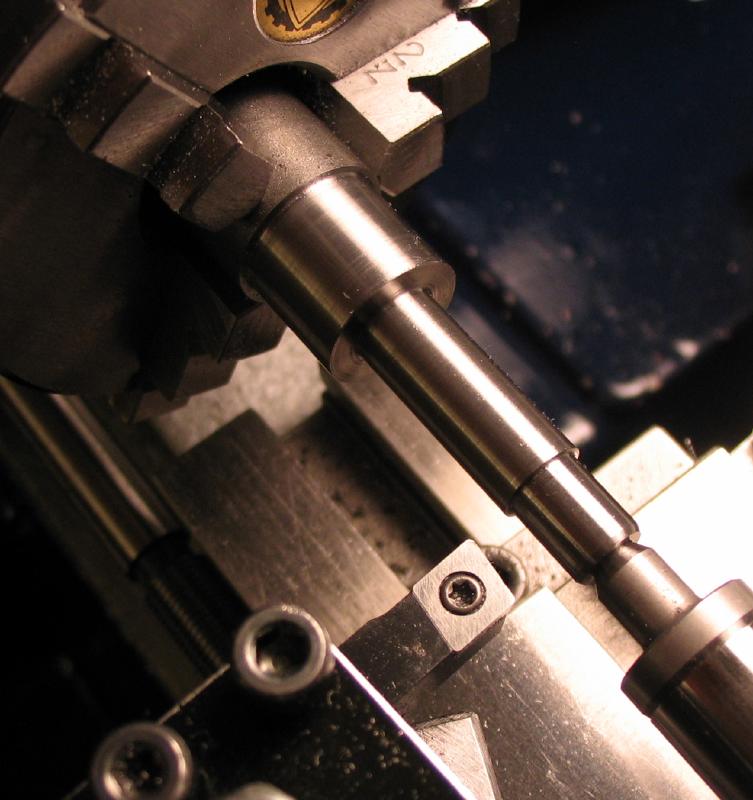
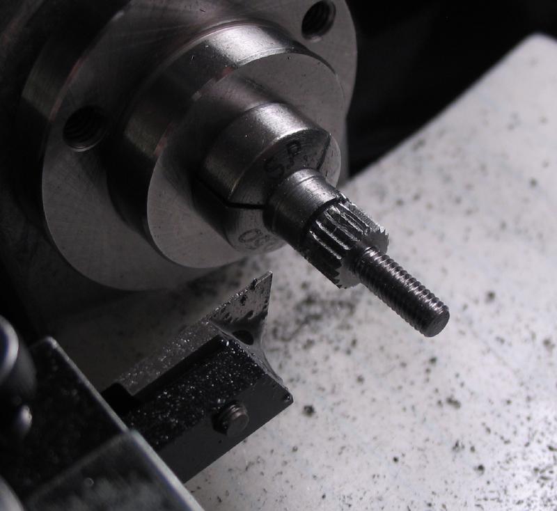
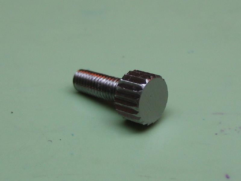
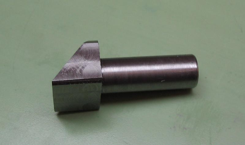
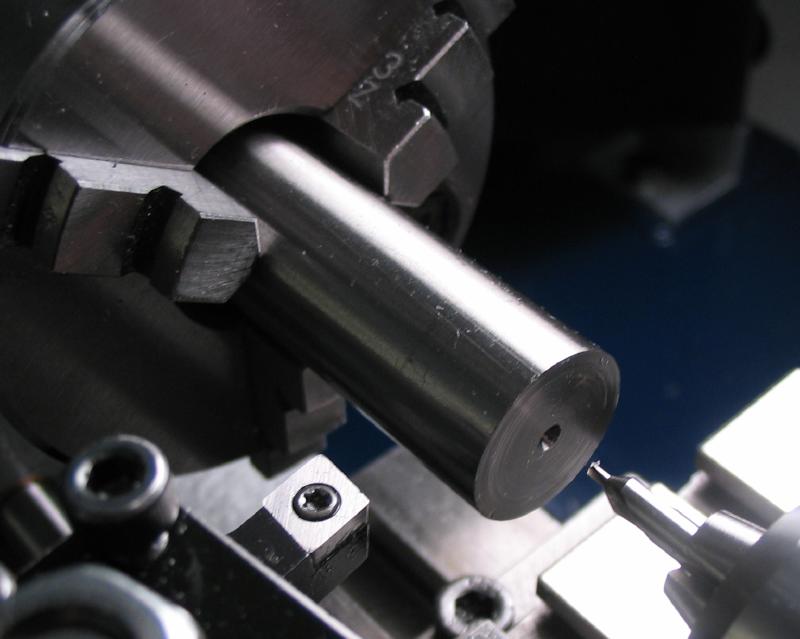
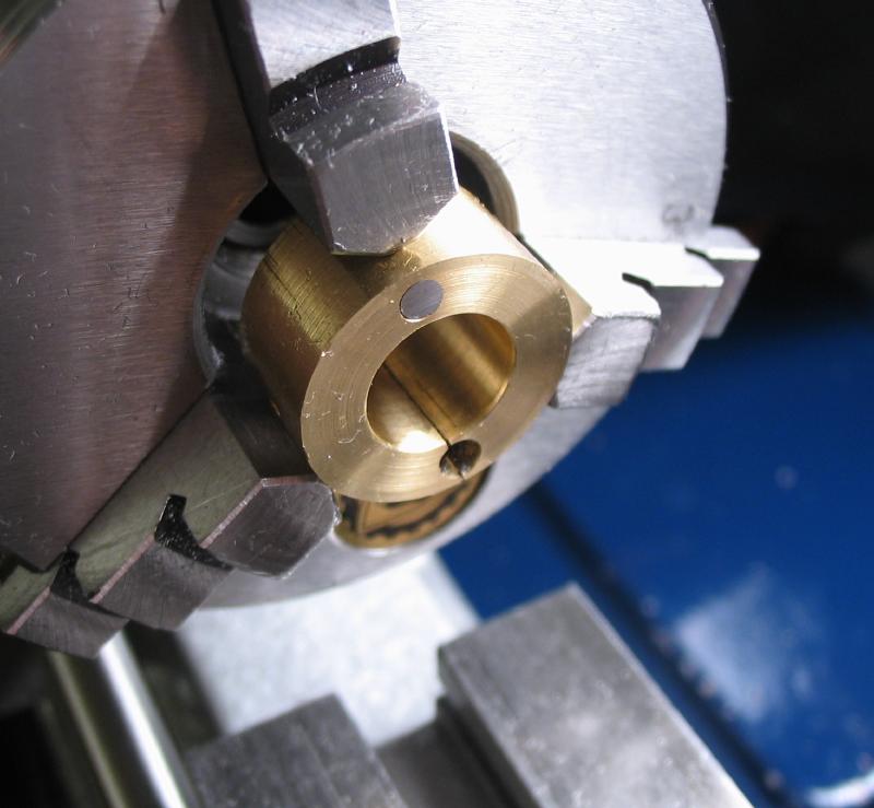
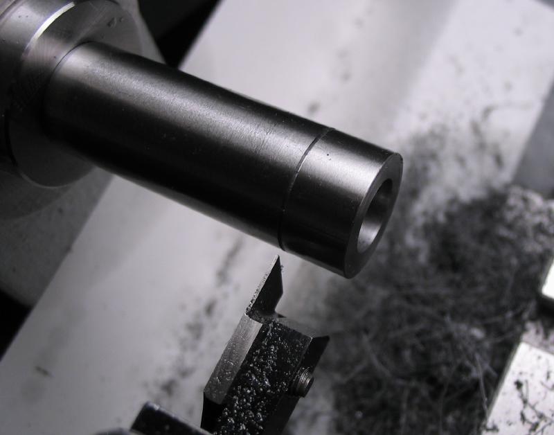
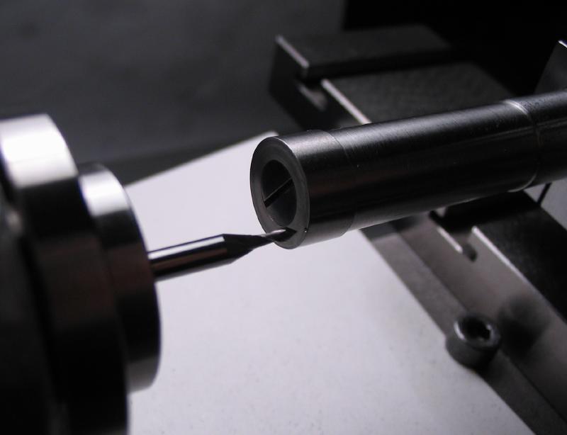
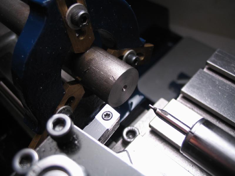
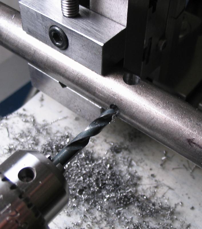
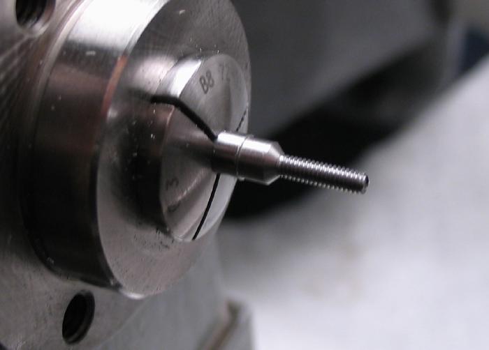
Headstock Clamp
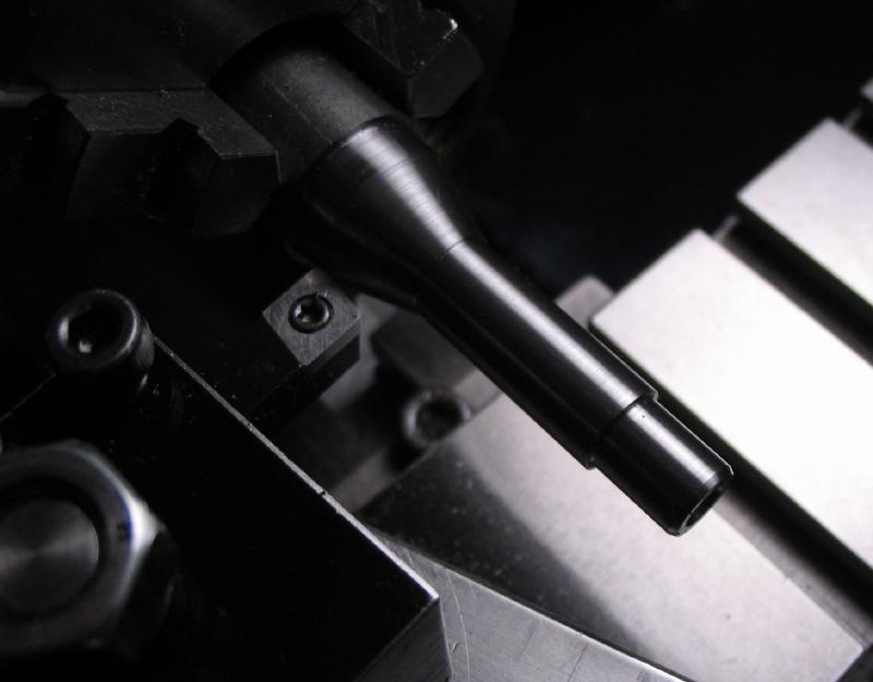
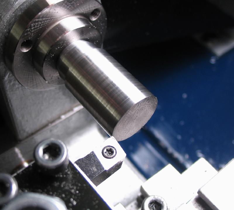
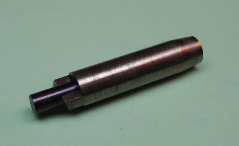
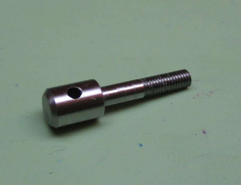
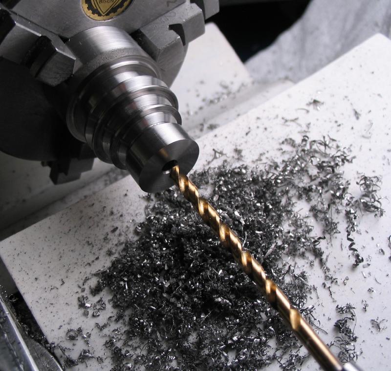
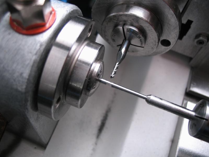
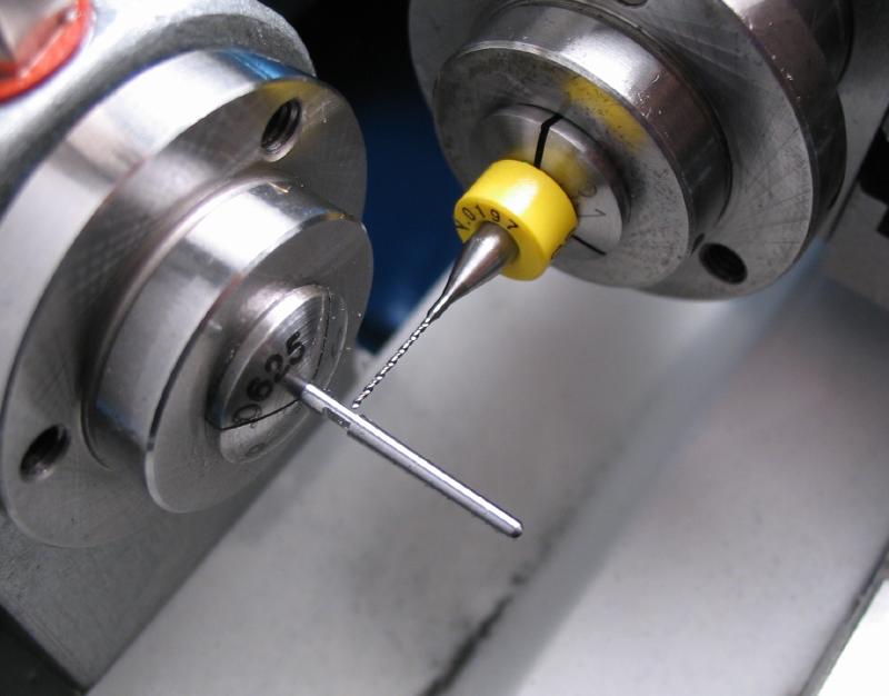
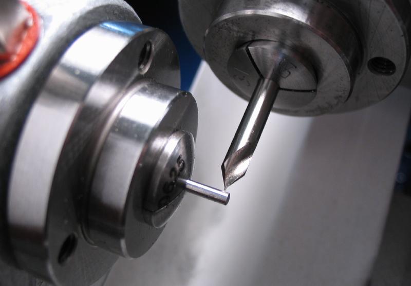
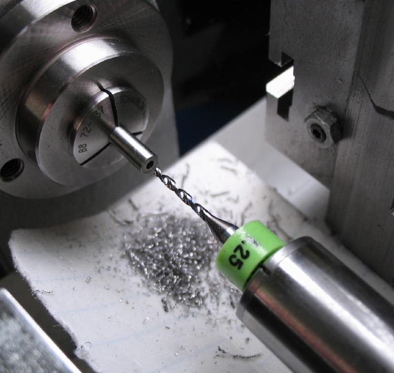
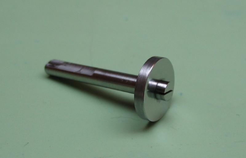
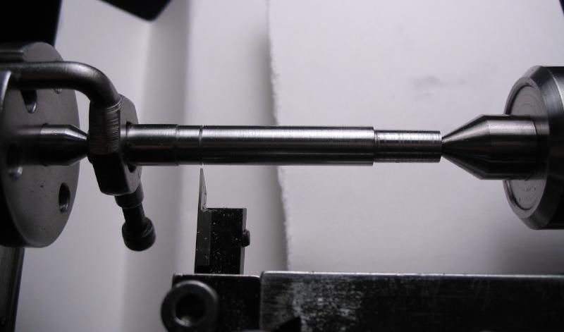
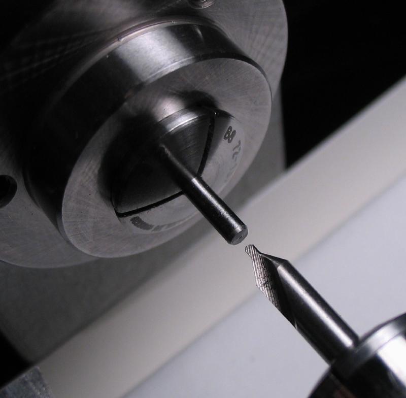
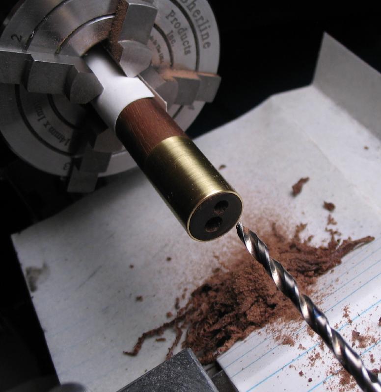
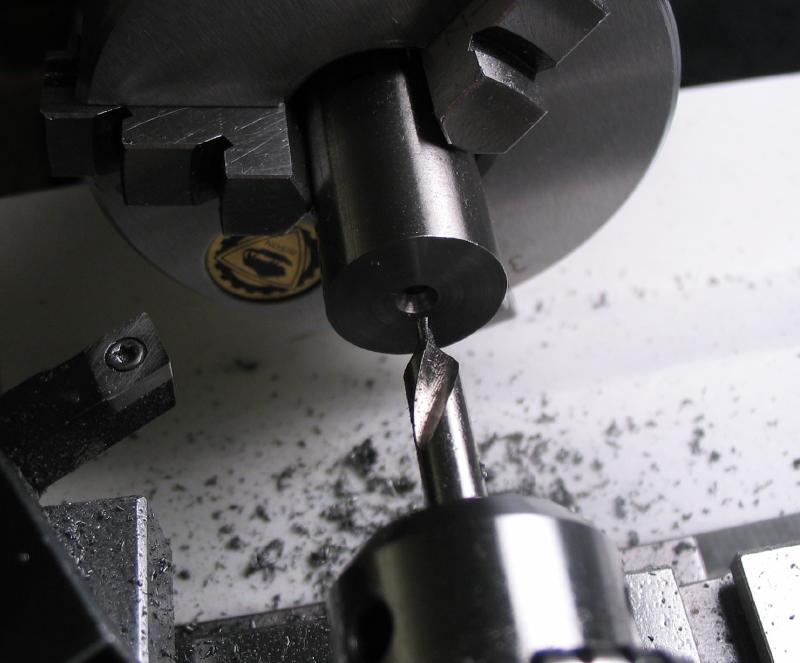
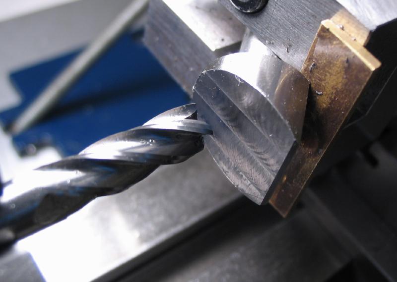
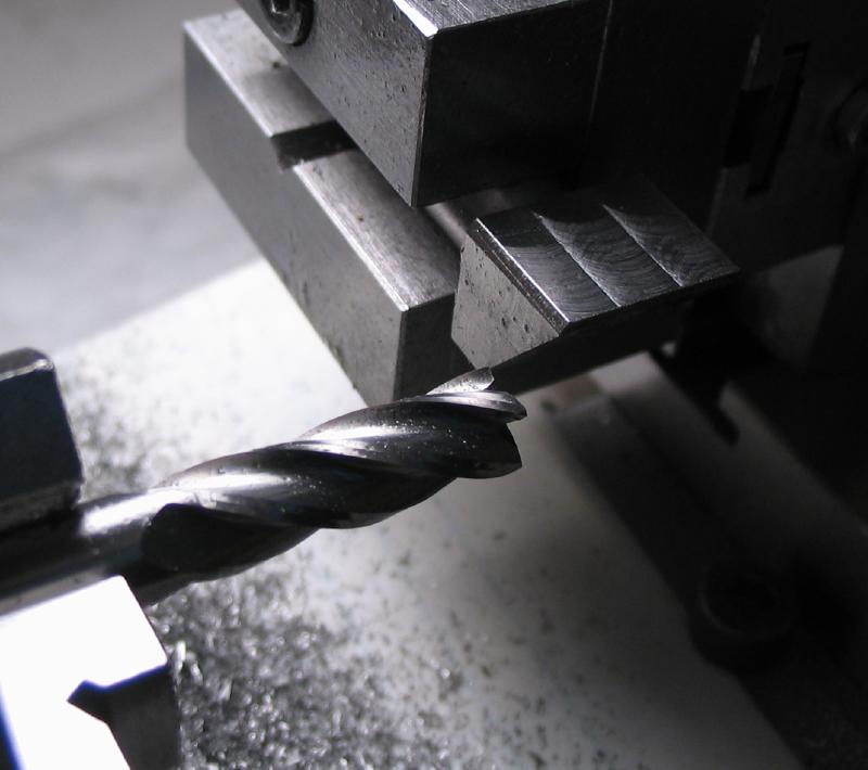
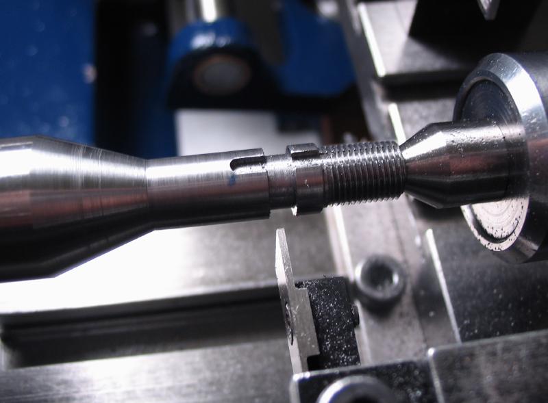
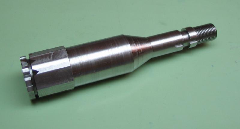
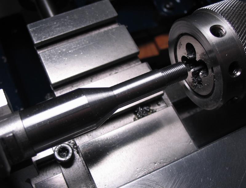
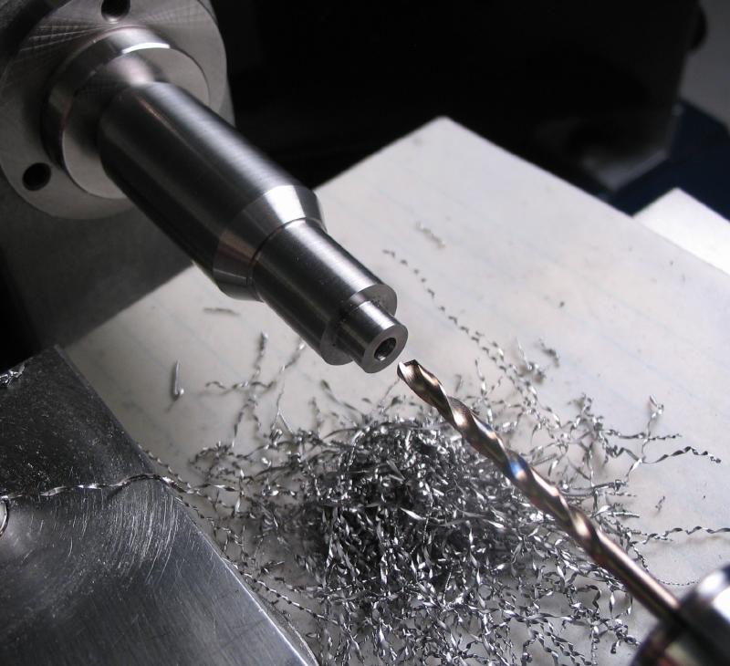
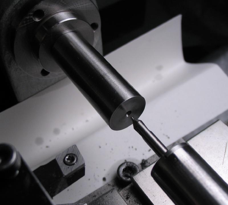
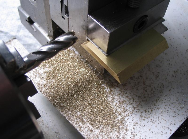
The project is started with the headstock mount. A B-8 shanked arbor was made from 5/8" mild steel rod. I've demonstrated this process a number of times now, but I will attach some photos that were taken. See the following page for more details (End mill arbor).
 |
 |
 |
 |
 |

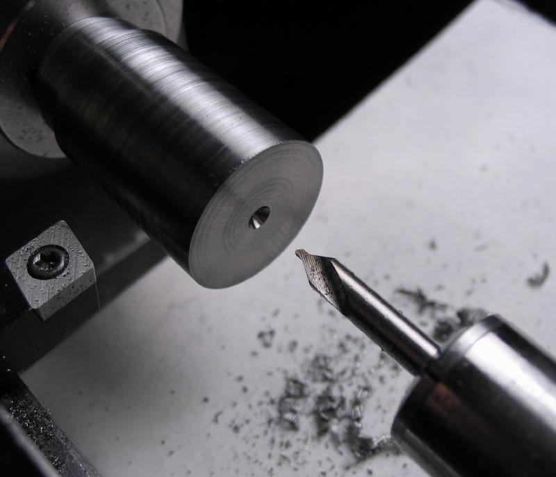
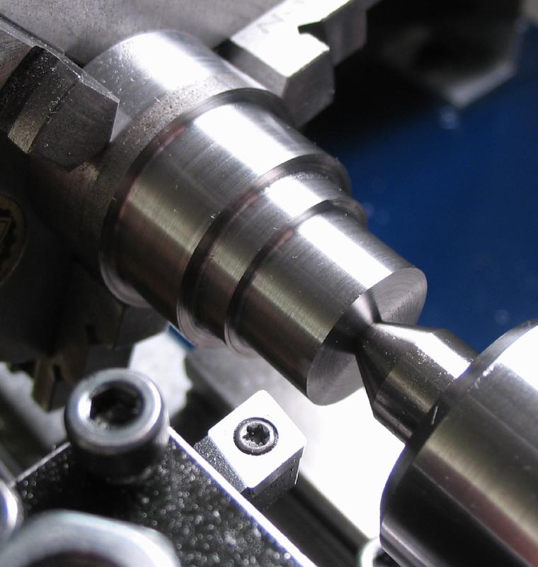
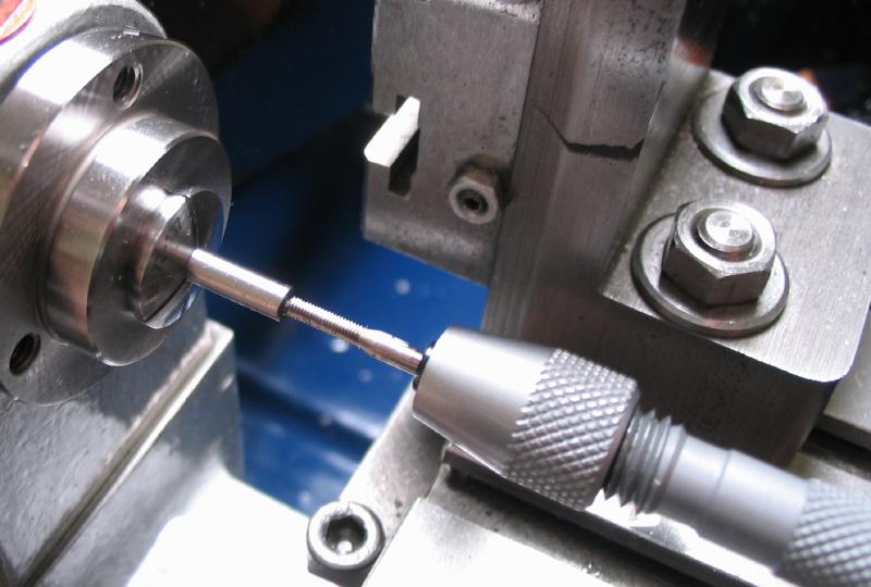
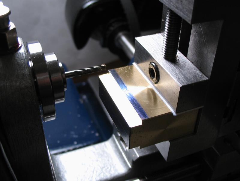
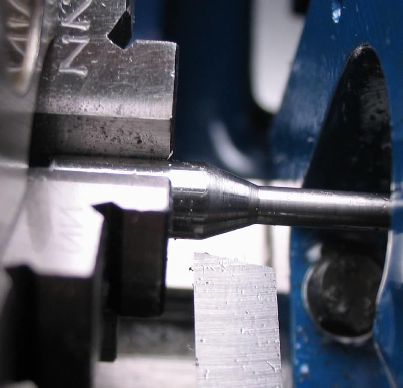
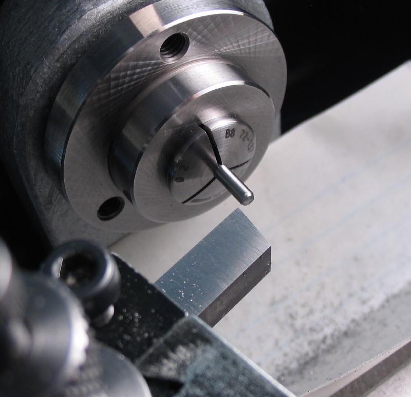
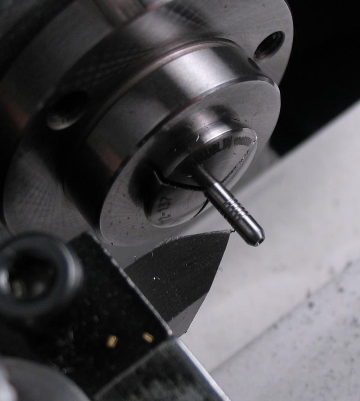
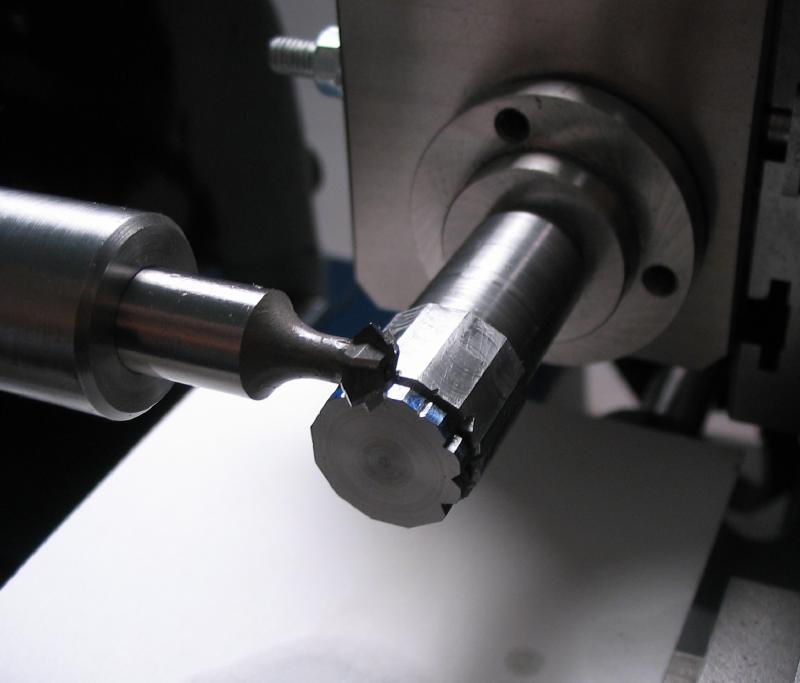
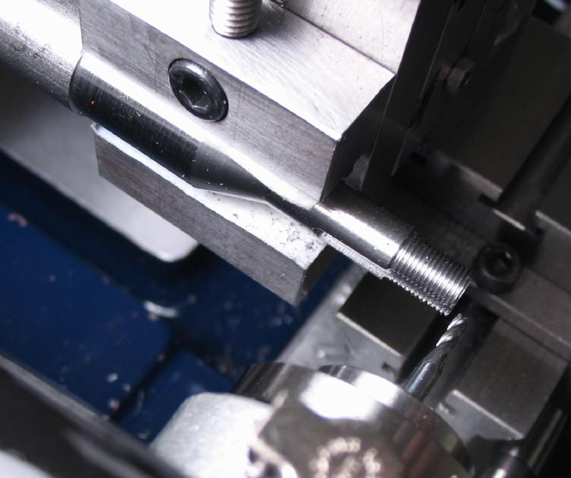
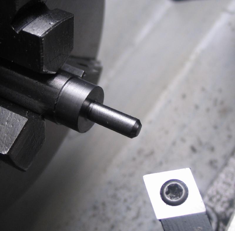
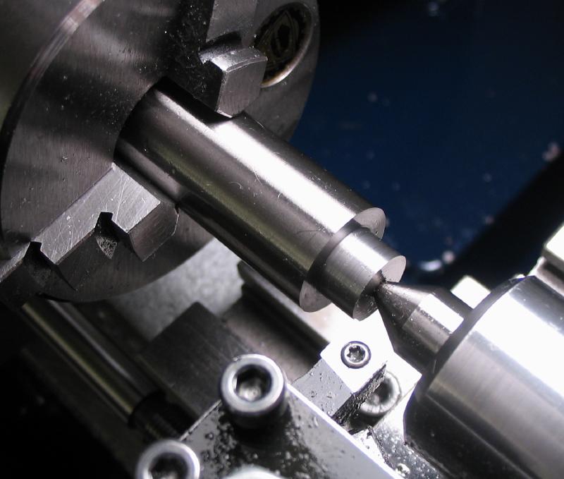
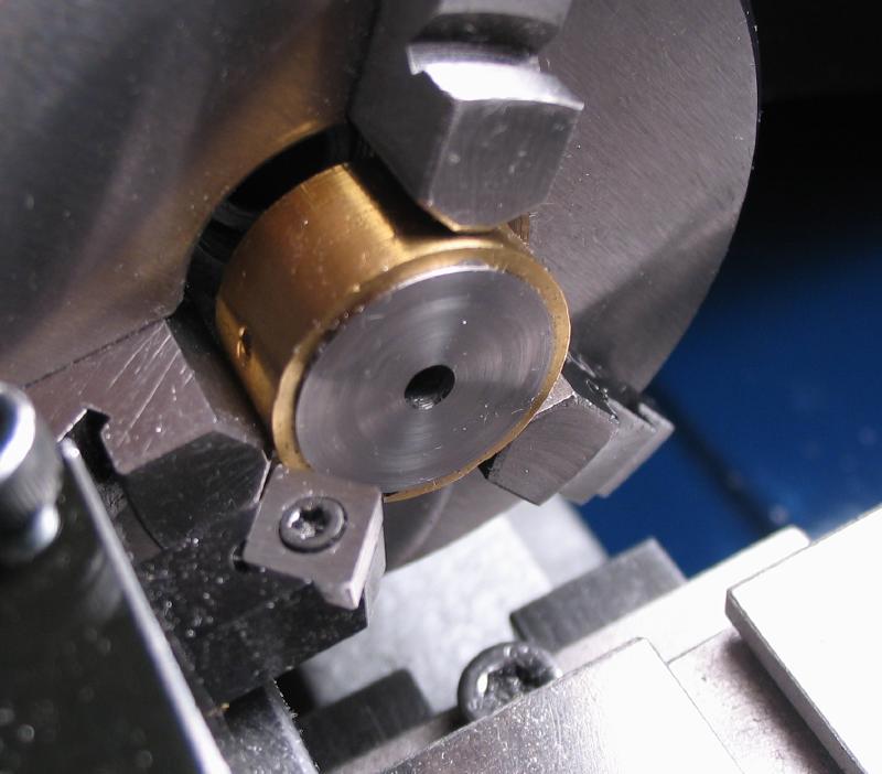
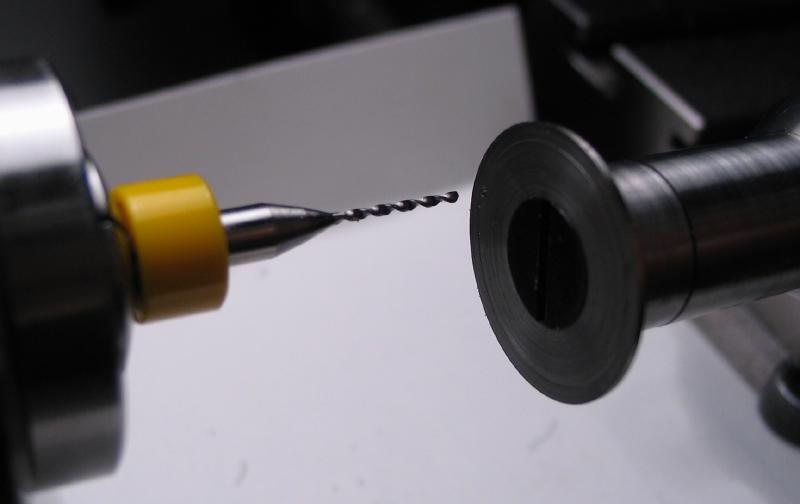
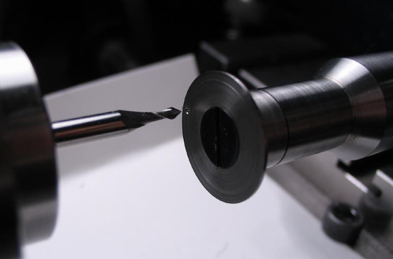
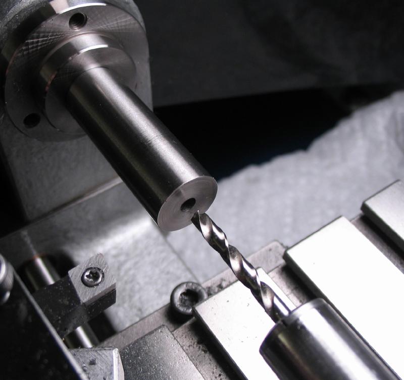
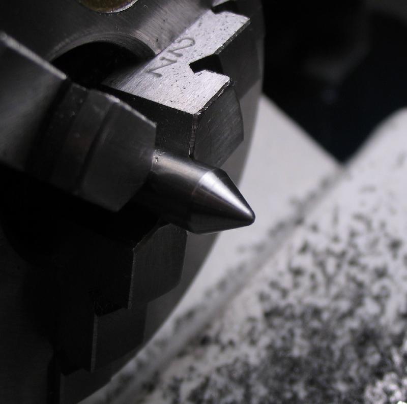
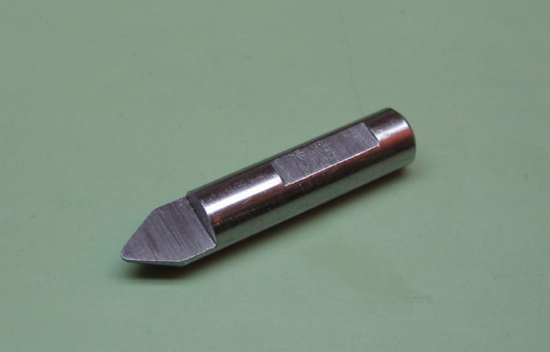
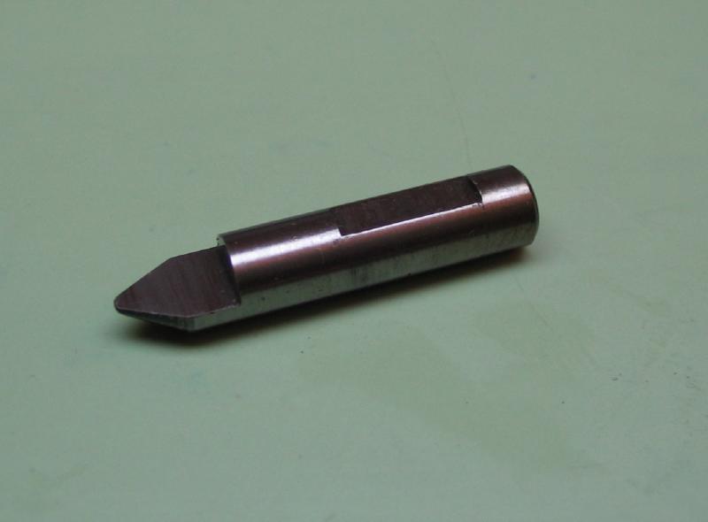
The clamping end of the arbor can now be formed. The work is mounted in the headstock and secured with the drawbar. It is turned true and faced. A center drill mark was made for marking the center position. The work was then transferred to the dividing head to mill a central section 7.0mm wide and 4.5mm deep.
 |
 |
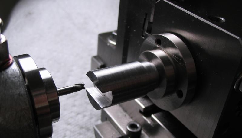 |
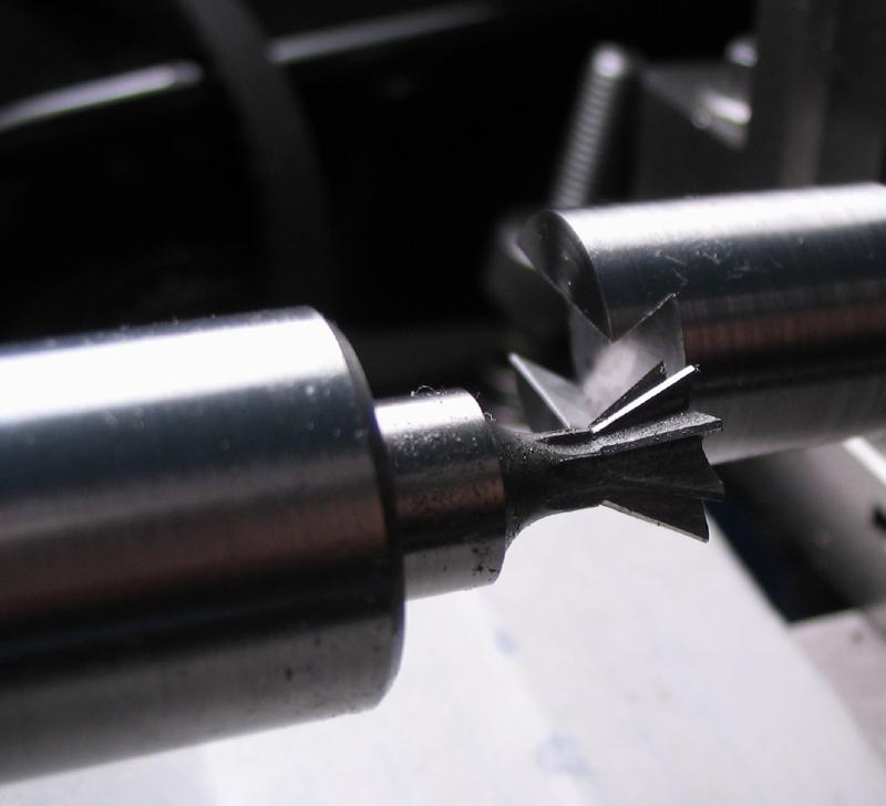
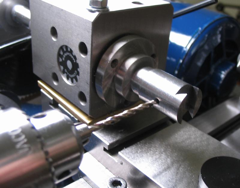
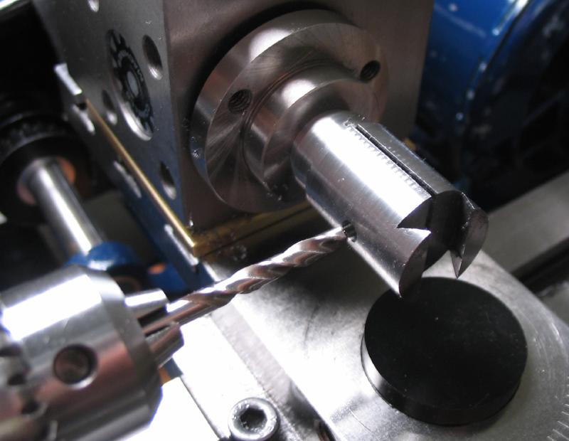
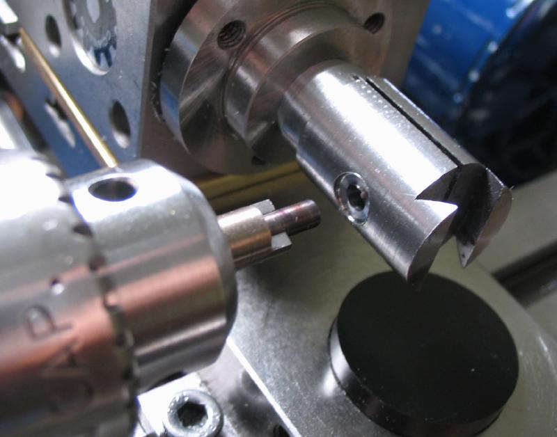
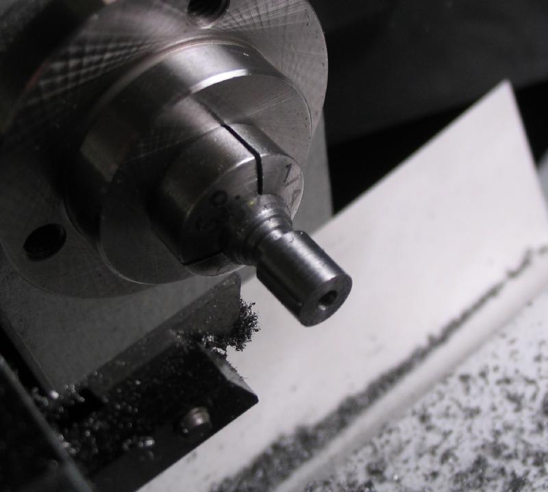
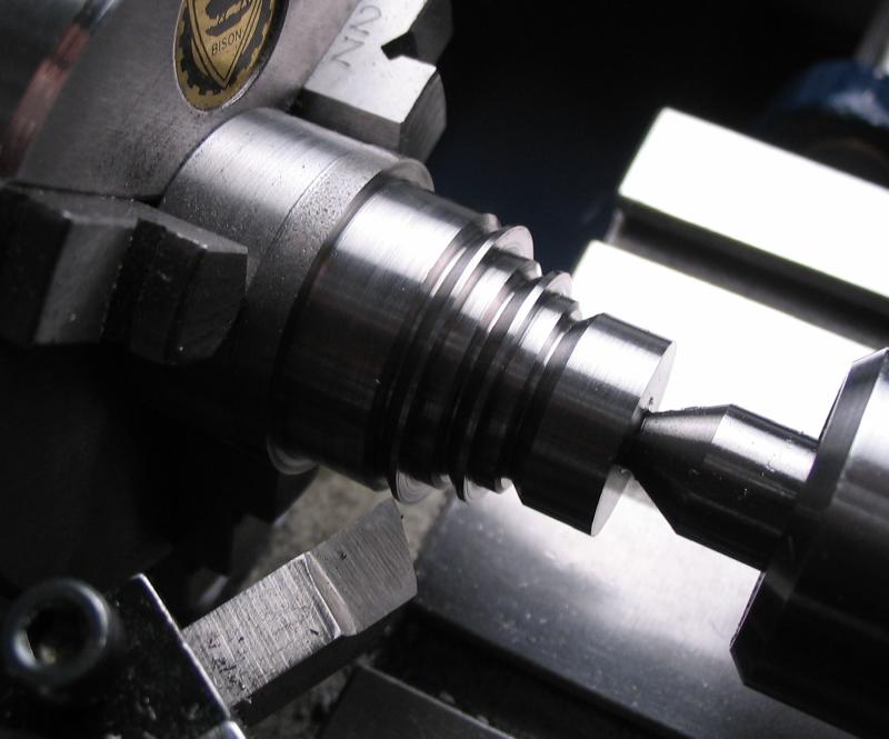
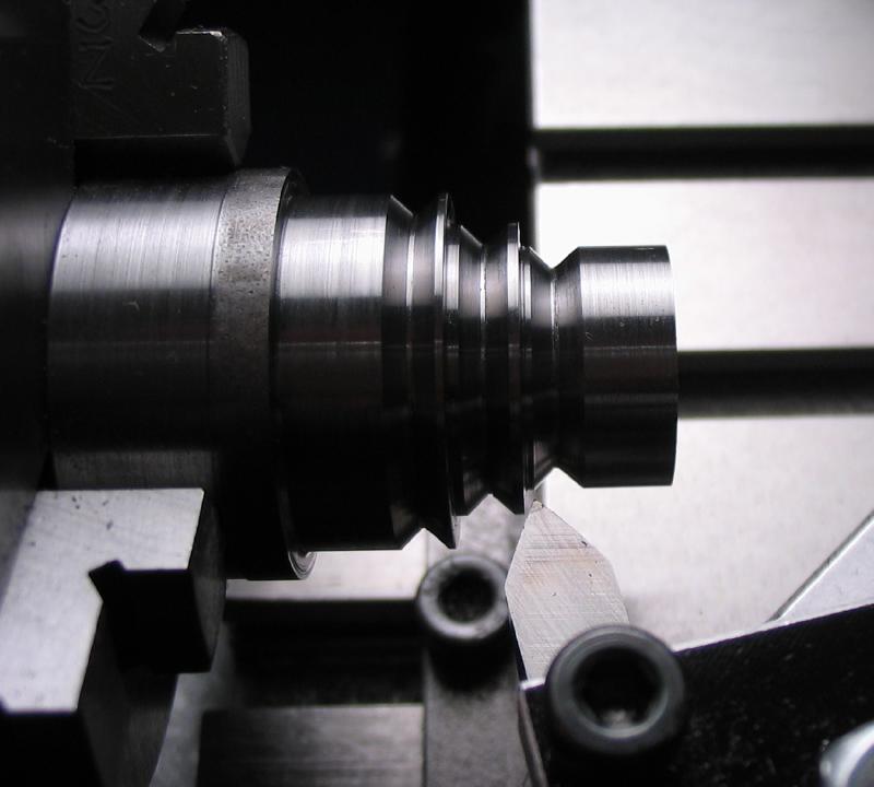
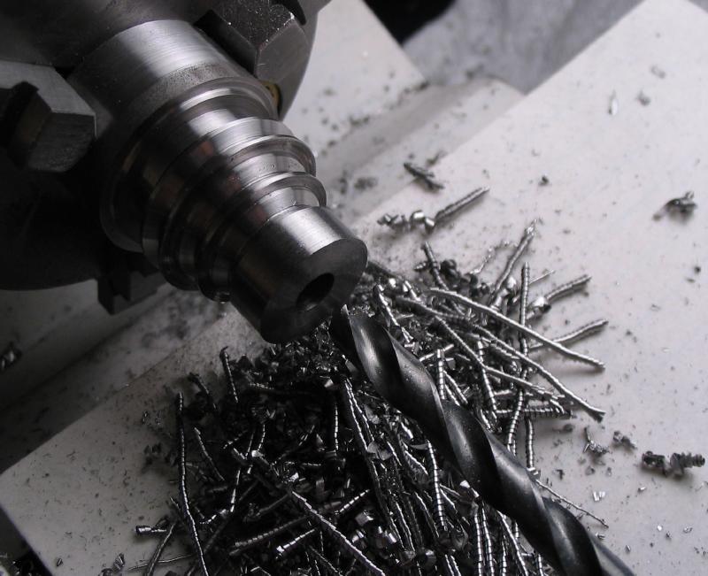
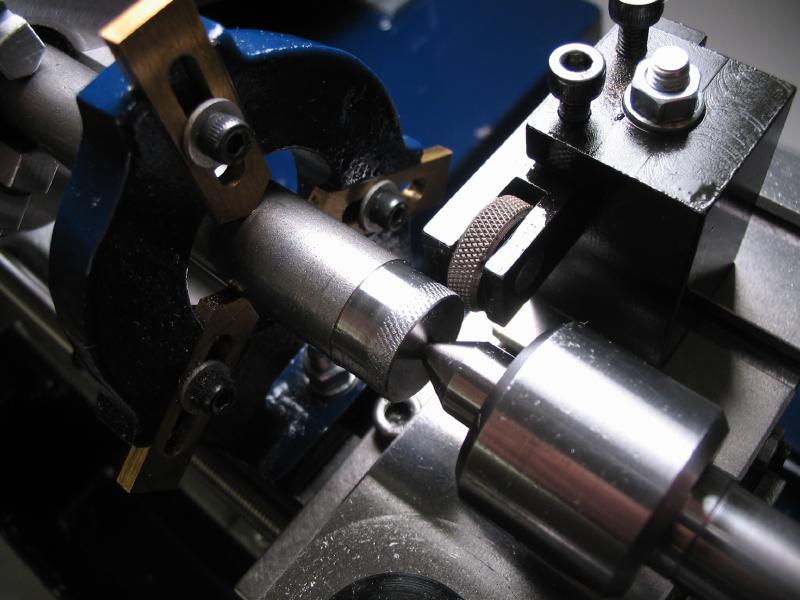
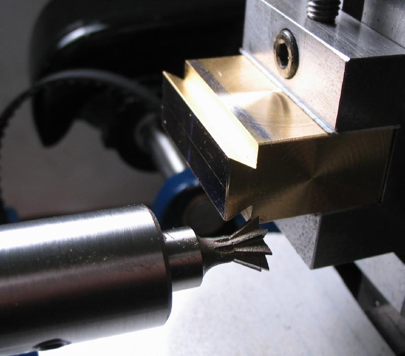
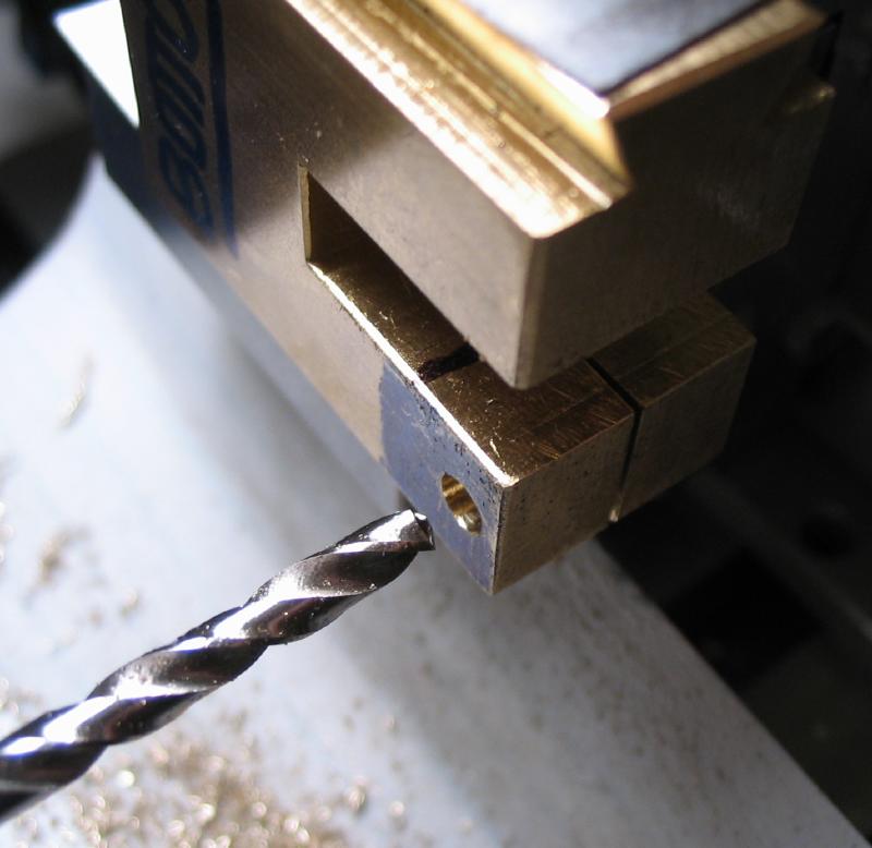
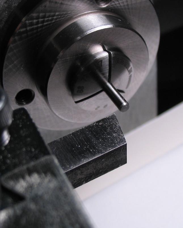
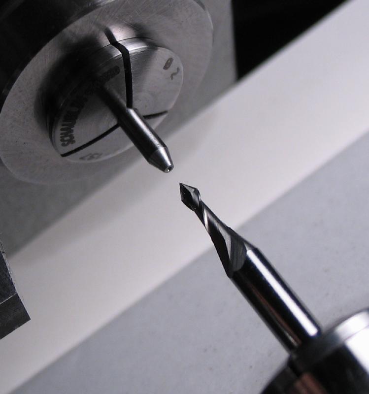
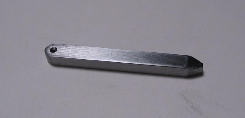
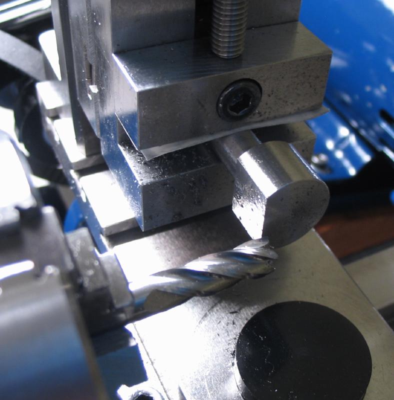
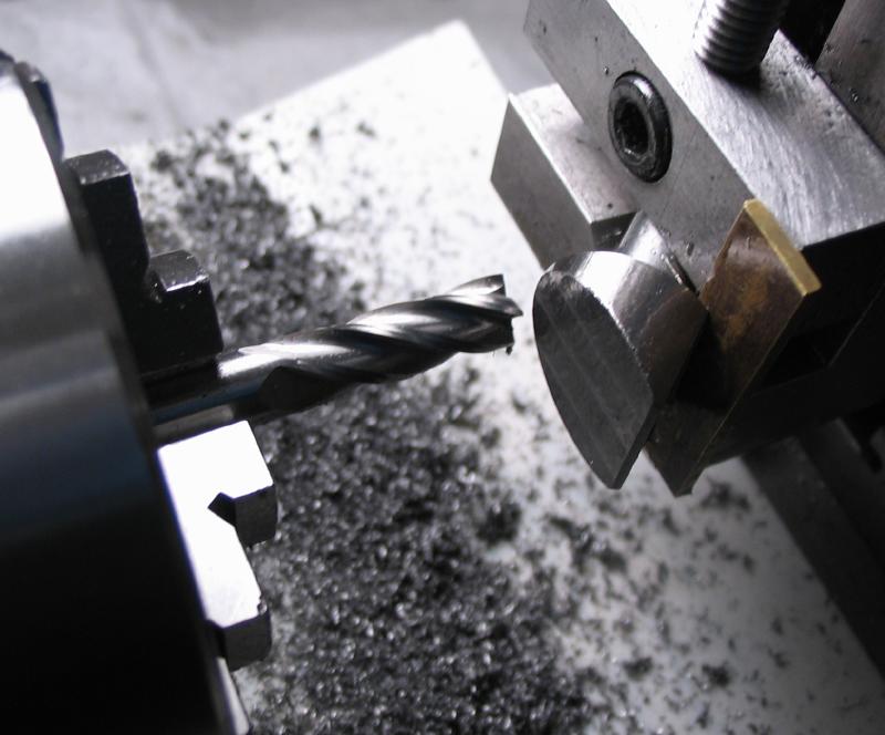
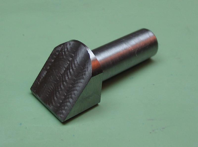
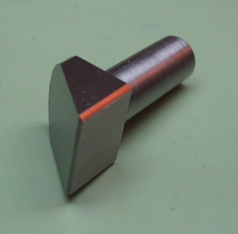
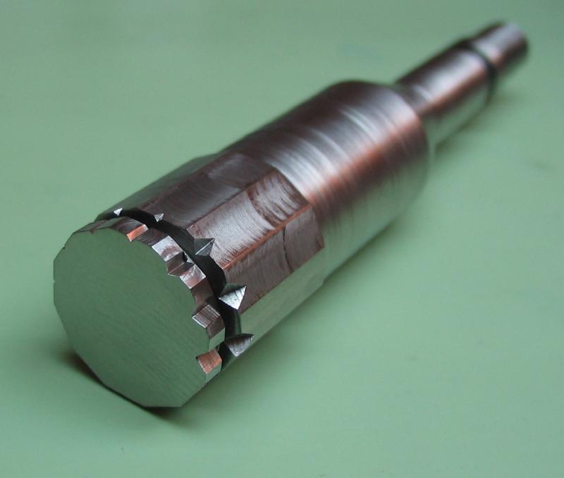
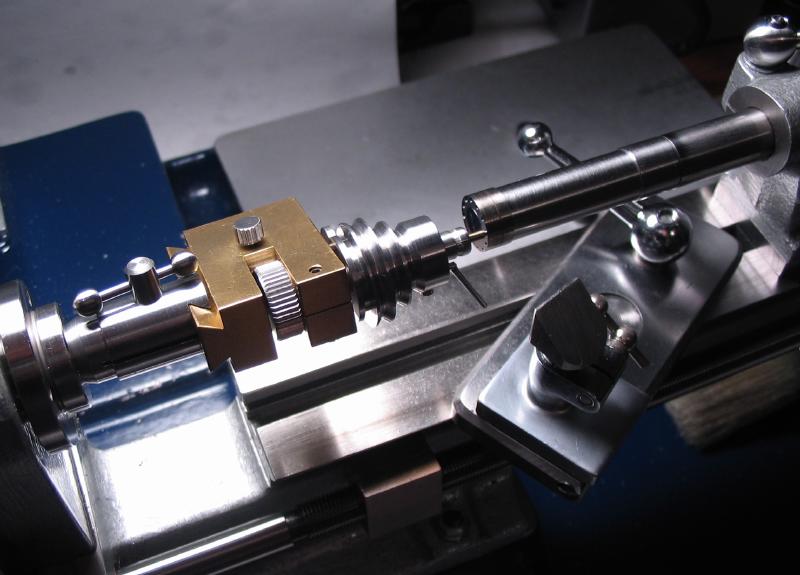
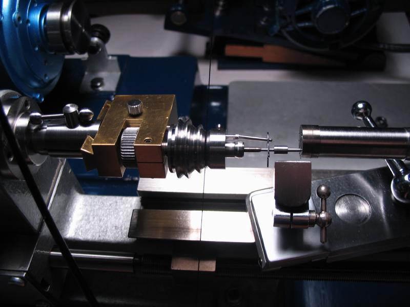
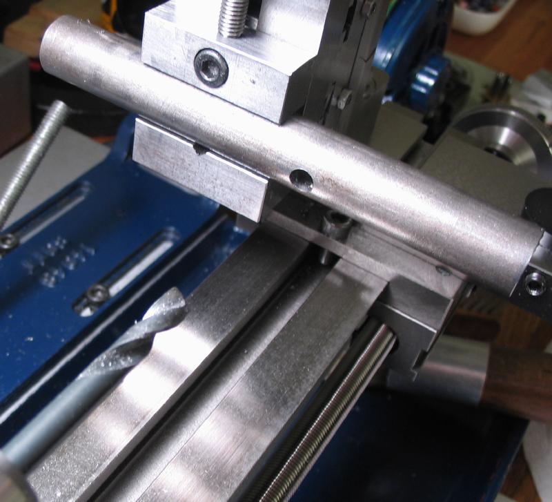
The next step is to mill dovetails. A 3/8" 60 degree dovetail cutter was used. The cutter shown is a Whitney 903760M42 cutter. It is held in a custom made arbor, described on the page mentioned above. Unfortunately, the method of holding the work was much less than ideal, and although it worked, I would not recommend it. I intended to use the dividing head, but was unable to position the work at the correct heights. The arbor was held in a collet holding pin-vise which was mounted in the toolmakers vise on the vertical slide.
 |
 |
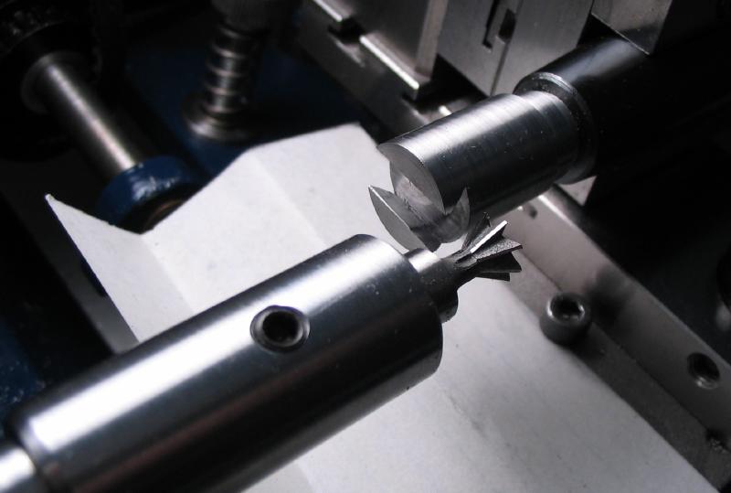
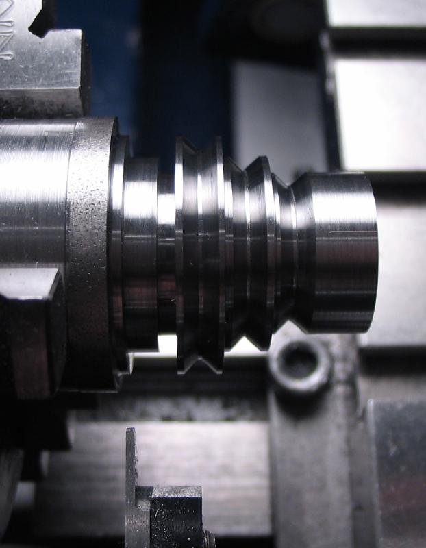
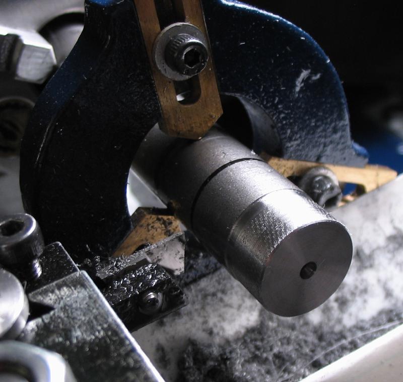
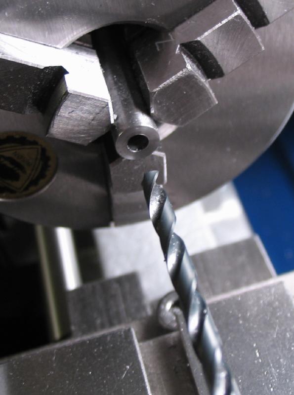
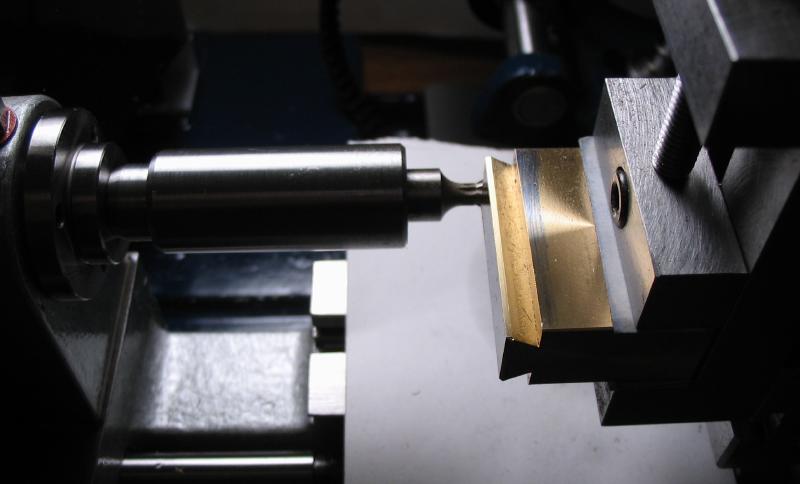
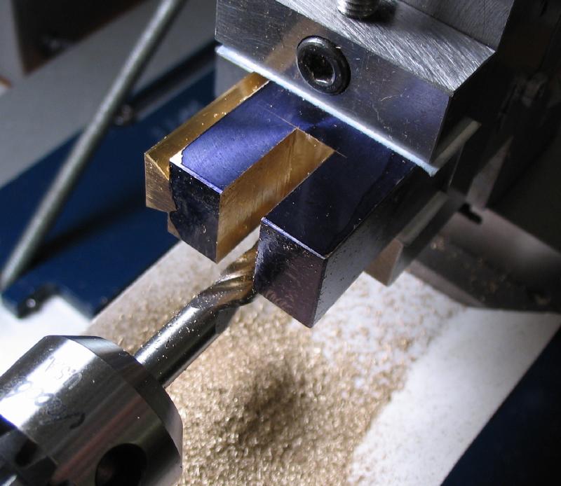
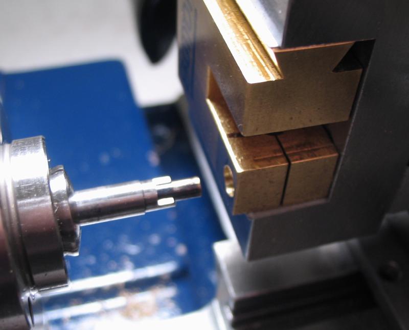
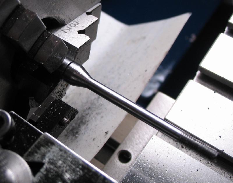
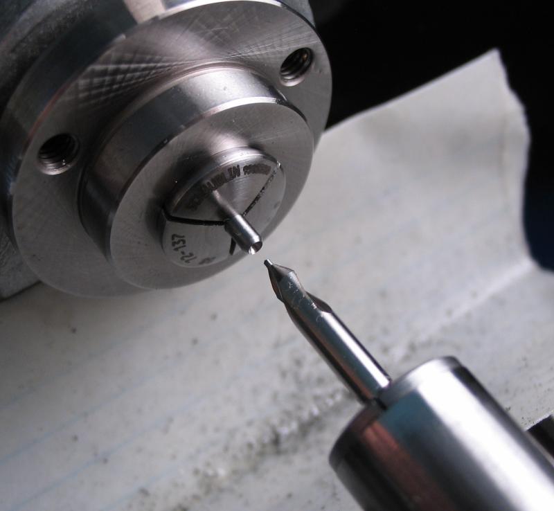
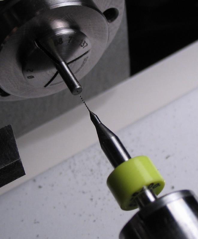
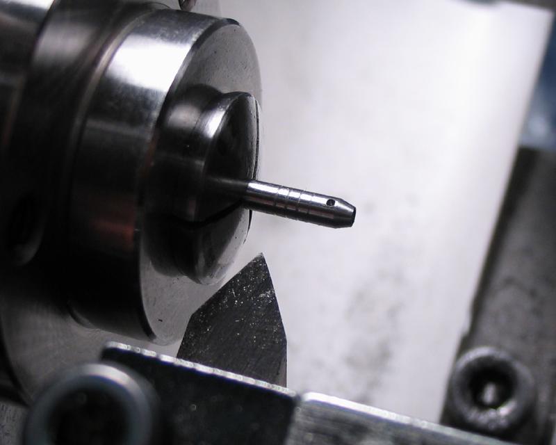
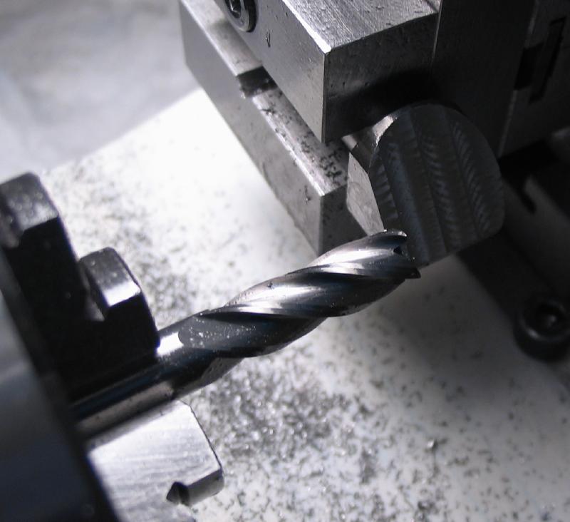
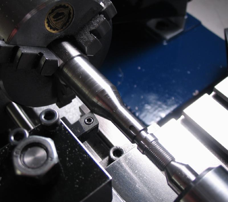
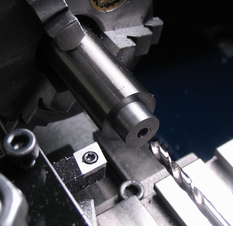
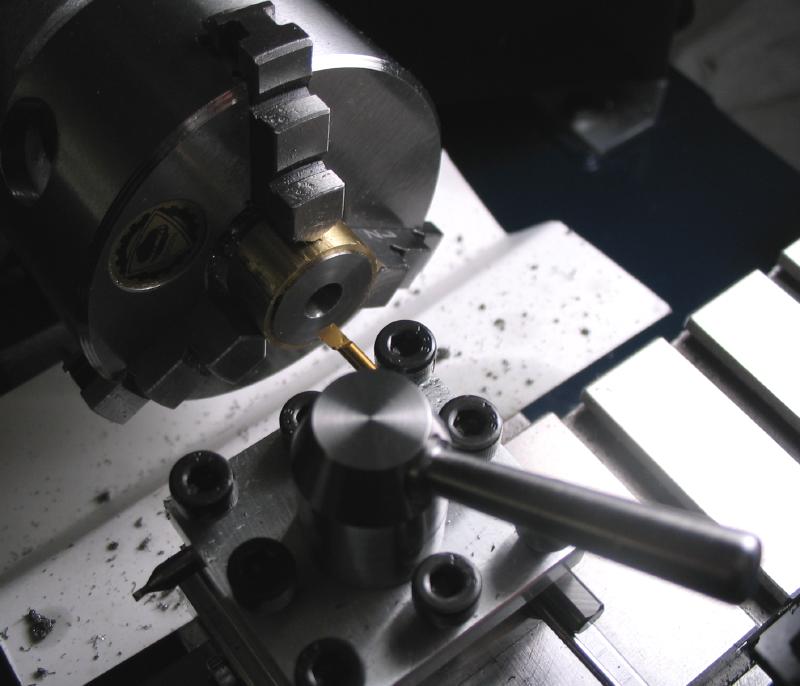
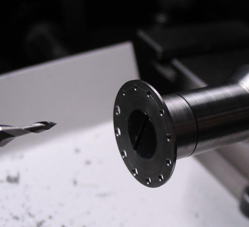
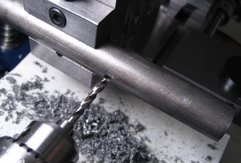
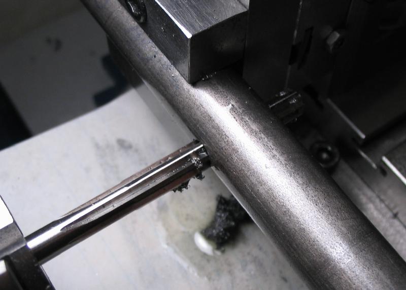
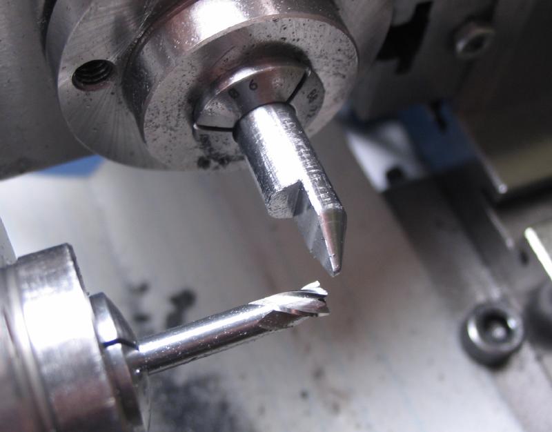
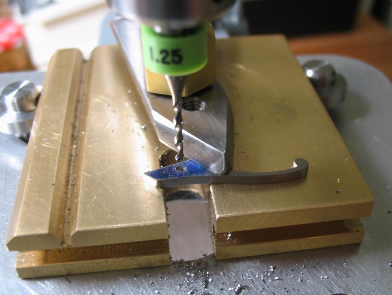
The arbor is returned to the dividing head for cross drilling 2.5mm. This will be later threaded for the locking lever.
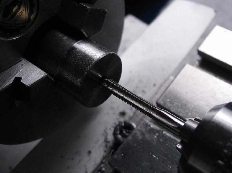
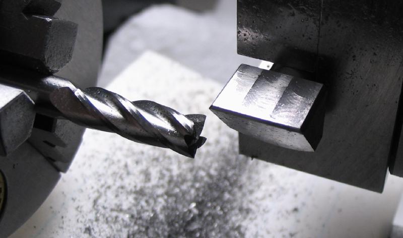
The end of the arbor is now slotted with a 0.8mm slotting saw. The arbor is held in the headstock and locked. After slotting it was returned once again to the dividing head to open the drilling half way to pass the screw. The other side is threaded M3x0.5 with a tap.
 |
 |
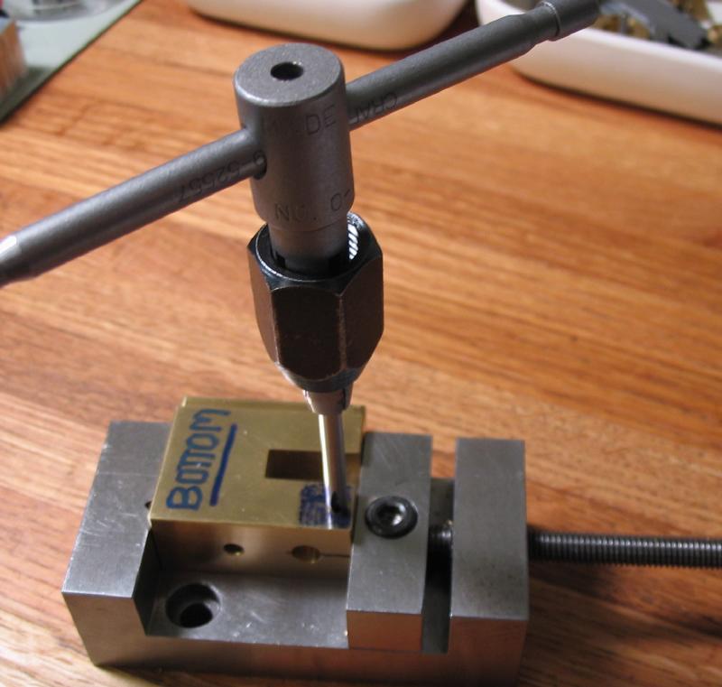
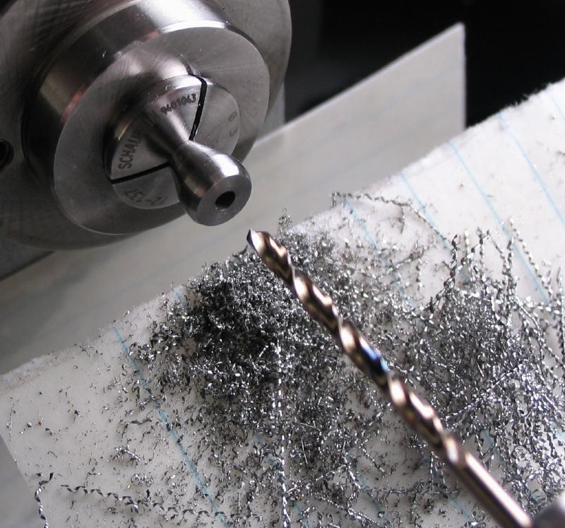
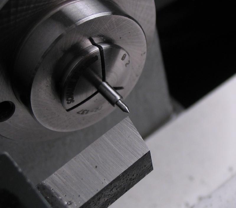
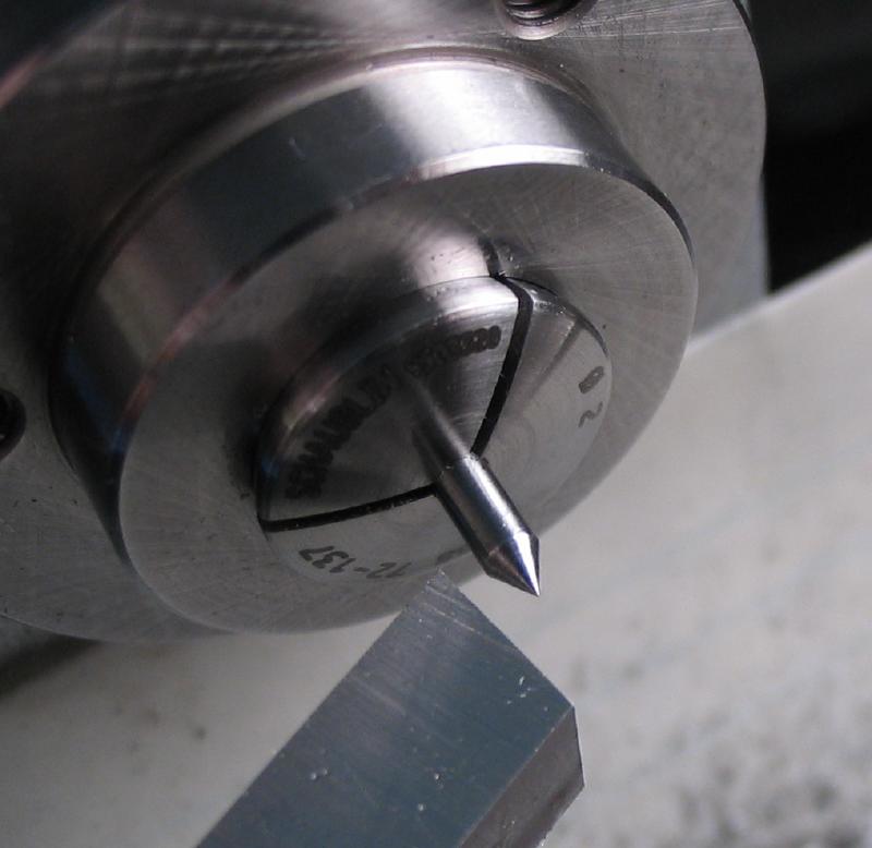
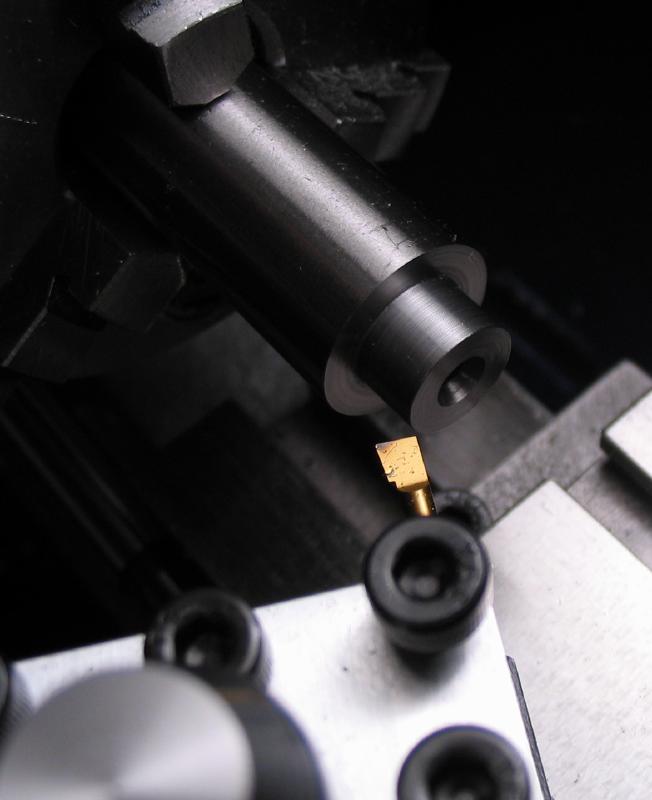
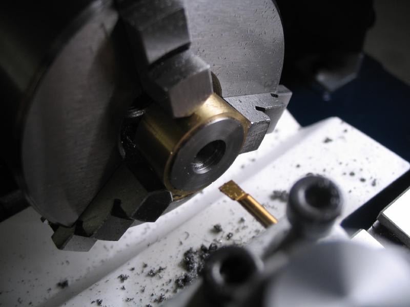
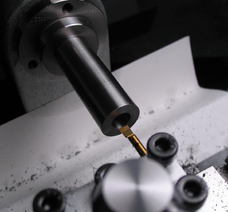
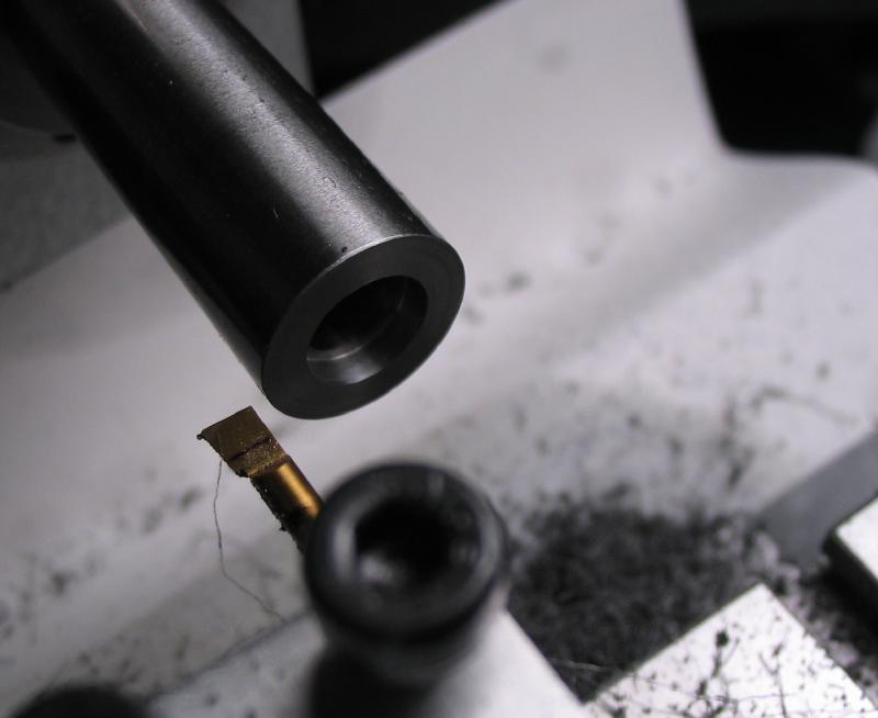
The hole is counterbored to seat the securing screw. A counterboring tool needed to be made. 6mm O-1 drill rod was drilled 1/8" to fit a pilot, and then mounted in the dividing head to mill the faces of the cutter.
 |
 |
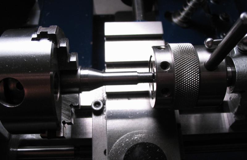
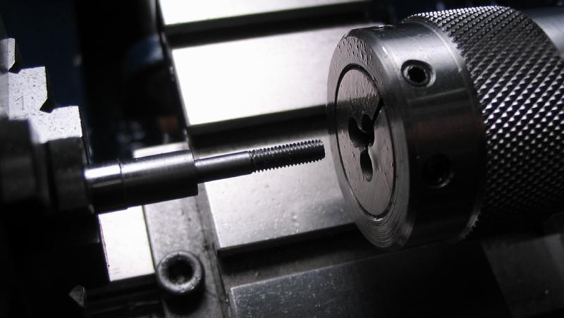
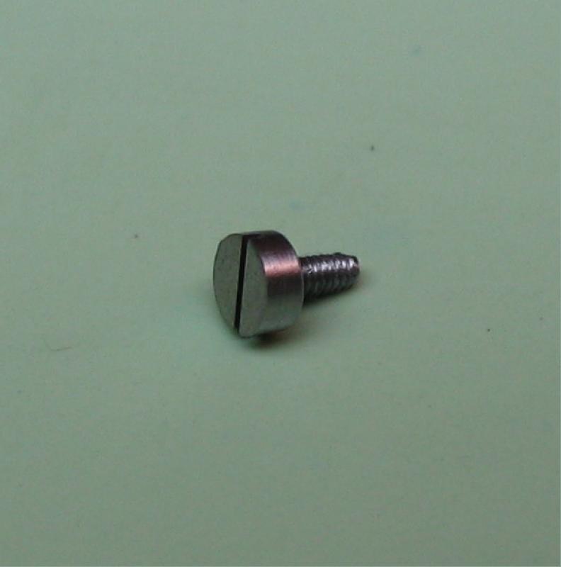
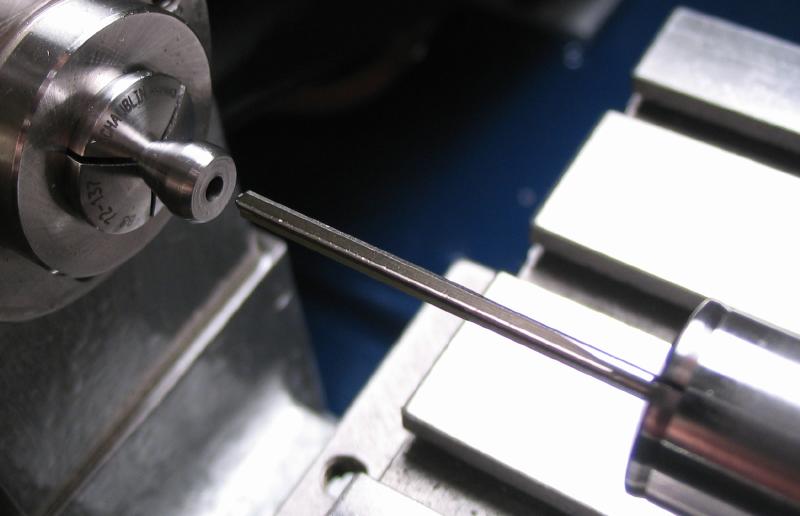
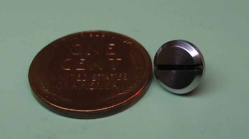
The securing screw is made from 1/4" O-1 drill rod, turned to dimension, and threaded M3x0.5 with a die. It can be then parted off.
 |
 |
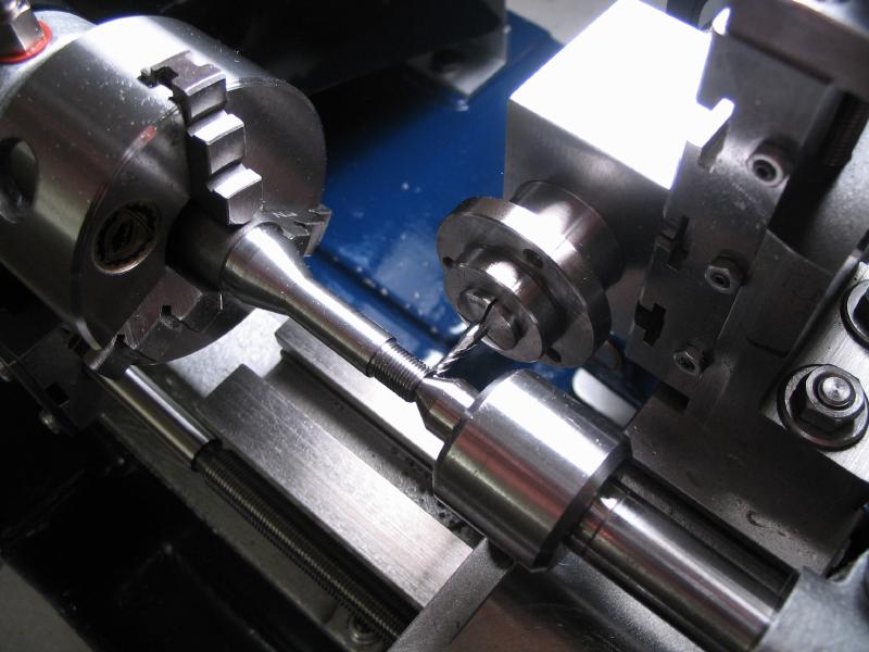
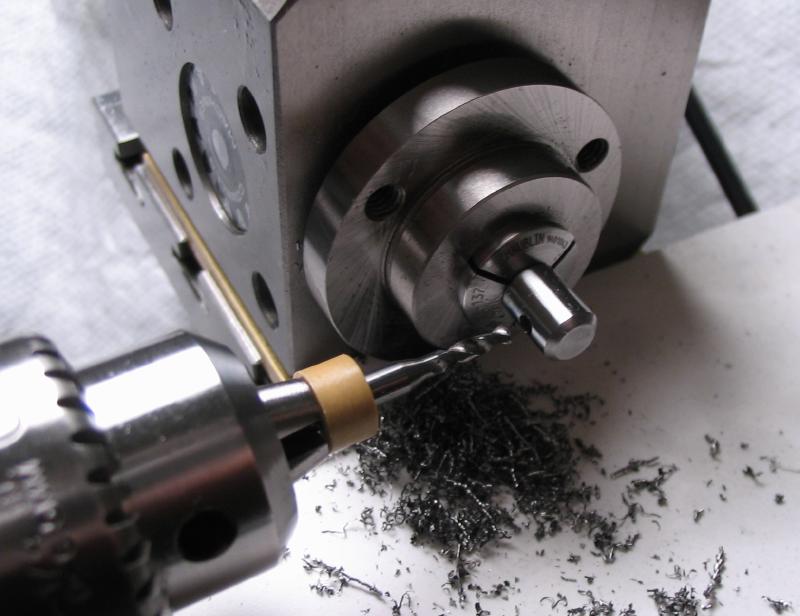
The screw is held by the plain portion in the dividing head and a 2.05mm hole is cross drilled in the head portion.
 |
 |
The handle for the screw is a 25mm length of 2mm drill rod and ball ends. The handle slips in the screw head to accommodate the limited space at the headstock.
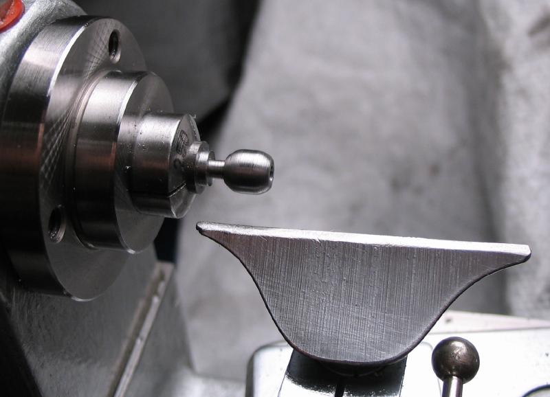
The ball ends are made from 1/4" 12L14 mild steel rod. The approximate shape is turned with the graver on the T-rest. The radius tool helps provide a clean finish.
 |
 |
 |
 |
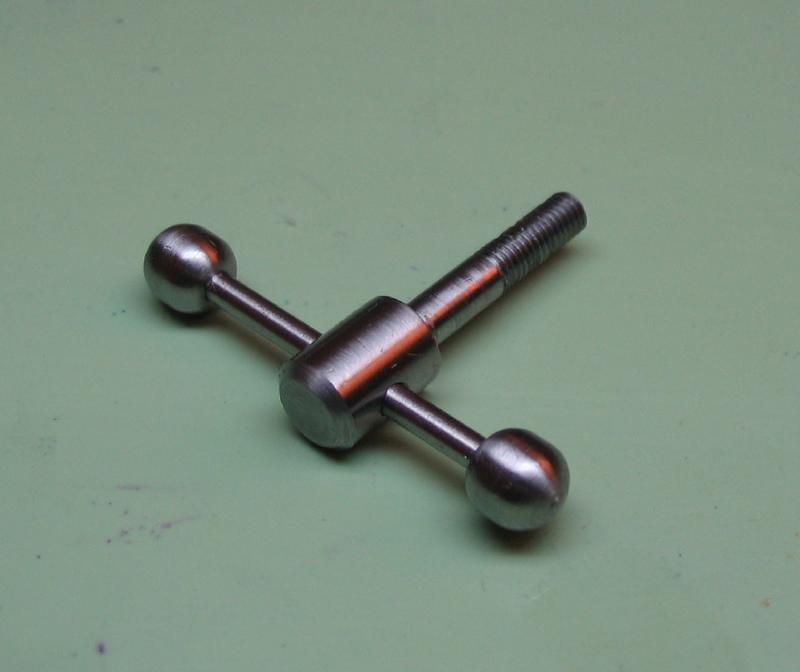
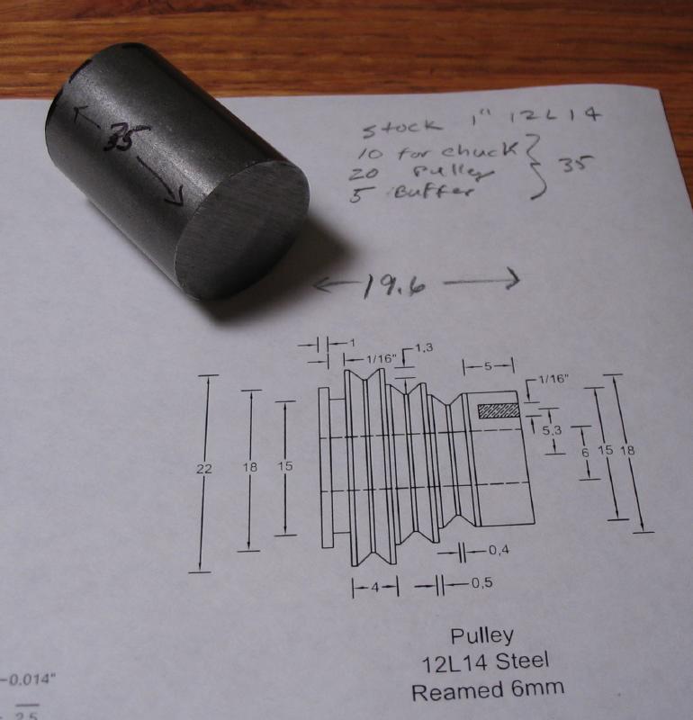
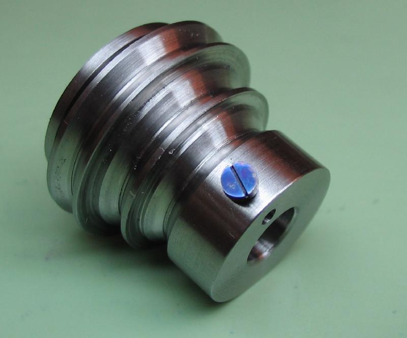
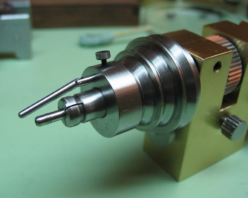
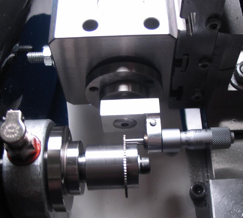
Drive Pulley
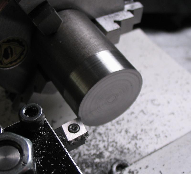
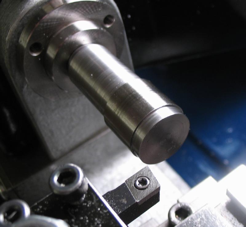
The drive pulley was made from a 35mm length of 1" mild steel rod (type 12L14). One end was faced and a 10mm length turned true, this allows for secure mounting in the 3-jaw chuck.
 |
 |
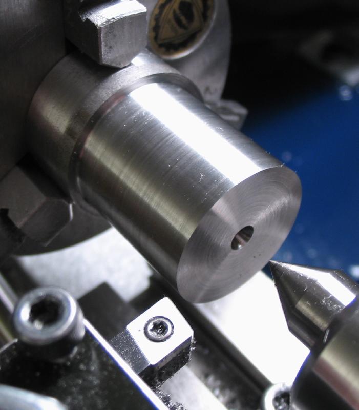
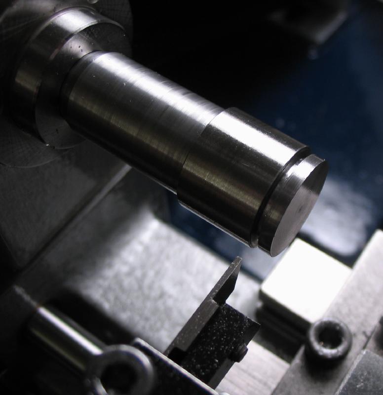
The reverse end of the rod was faced and center drilled for tailstock support. The major dimensions for the stepped pulley were turned.
(22mm, 18mm, and 15mm).
 |
 |
For each of the three pulley diameters a 1/64" (~0.4mm) parting tool was plunged into the work to form the center/base diameter.

The 45 degree sides of the pulley slots were turned using the compound slide and various tooling, whichever could fit into the tight spaces and provide a cutting edge. A right hand tool was used on the right sides of the pulley and a 60 degree threading tool was used to get at the left sides.
 |
 |
The retaining slot was plunge cut with the parting tool.
The work was then drilled, bored, and reamed 6mm. This is a bearing surface and needed to be concentric to the outside diameters and an accurate fit to its shaft.
 Drilled 1/8" as a starting diameter |
 Then drill 5.3mm |
 |
 |
The hole for the drive pin was drilled 1/16" using the dividing head to position.
 |
 |
The drive pin is held in place by a securing screw, the hole is cross-drilled 1.00mm to be tapped 1.2mm.

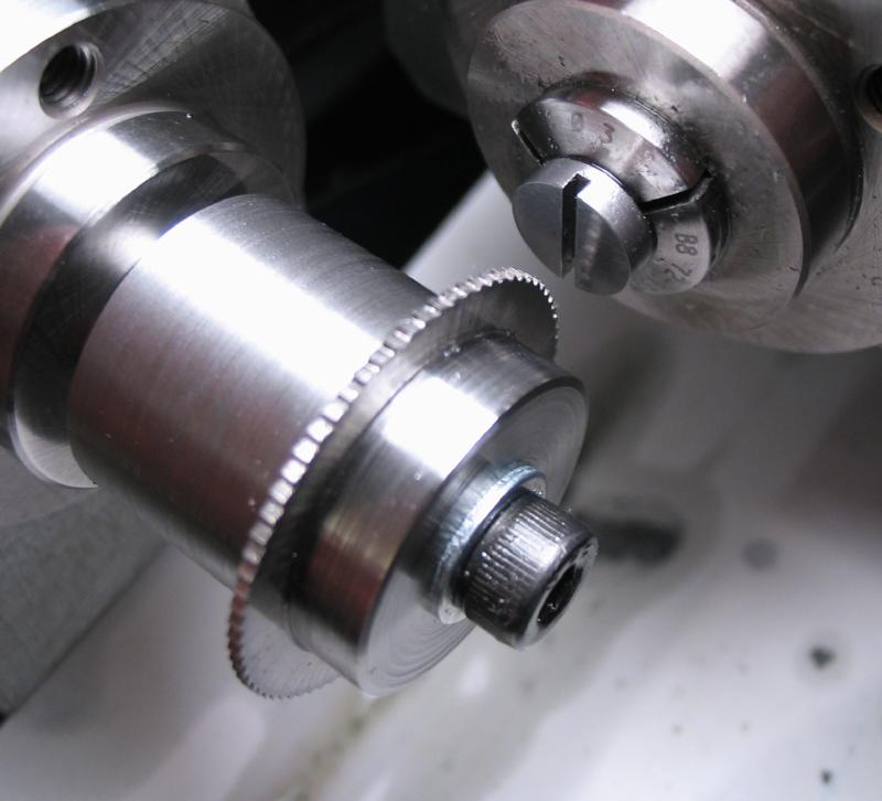
The pulley is parted off, a piece of brass rod is held in the tailstock to catch the pulley as it releases from the stock.
The tapping is performed on the drill press for alignment.
The completed pulley.

The drive pin securing screw was made from 3mm O-1 drill rod. It was turned to 1.17mm for threading 1.2mm. After threading it is parted off.

The slot was formed with a 0.010" slotting saw.
The screwhead was ground flat and polished with the previously made jig. It was hardened in oil and tempered to a blue color.
 |
 |
 |
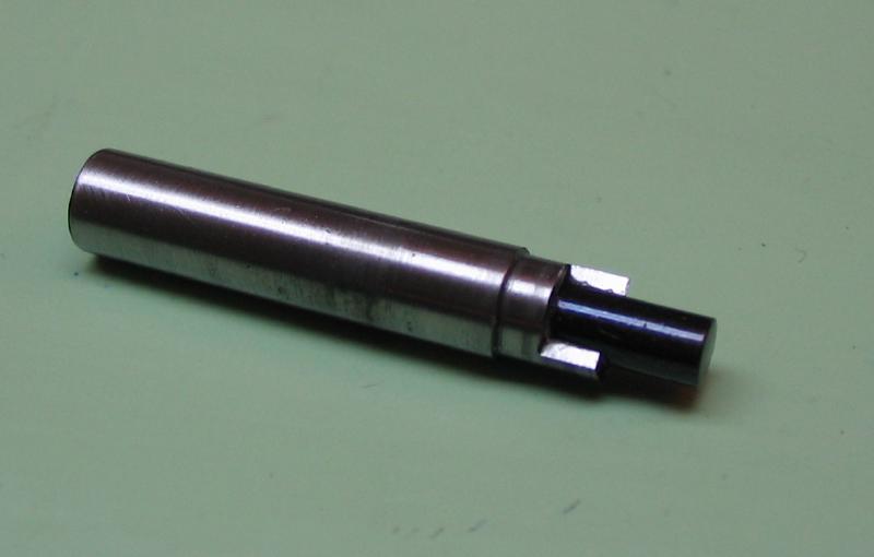
The drive pin was made later on, but placed here for continuity. It is made from 1/16" O-1 drill rod. To provide some flexibility in application, it was designed with an articulation. First a length of rod was taper turned (~1 degree) and milled with a 1.5mm end mill. The headstock is locked for the milling step and indexed 180 degrees to repeat the milling on the reverse side.
The milled flat was drilled 0.5mm and then the work parted off.
Another length of 1/16" rod was mounted in the collet and cross drilled 0.5mm. The end was slotted with a 0.025" slitting saw.
 |
 |
 |
The two segments are joined with a tapered brass pin. The pin is secured and riveted over on the staking tool.
 |
 |
 |
 |
Retainer
The pulley is designed so that small adjustments in position can be made. The pulley will be held in place by a small disc that mates with the slot turned on the rear end. The disc is mounted on an adjustable rod.
The rod is made from 3mm O-1 drill rod. It was axially drilled 1.25mm and tapped 1.5mm.
 |
 |
The rod was transferred to the dividing head on vertical slide to mill a flat for securing the rod with a screw in use.
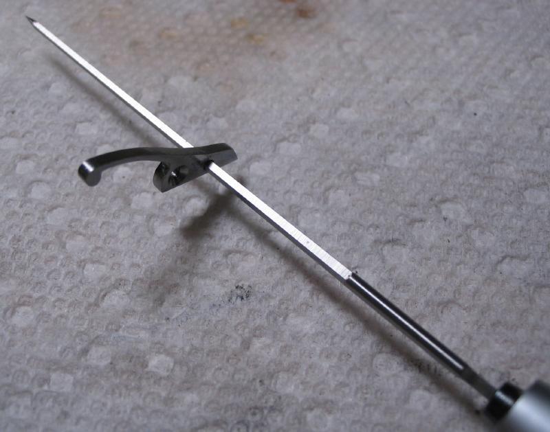
The retaining disc will pivot on a shoulder screw which resides on the end of the rod just made. The screw was made from 3mm drill rod and threaded 1.5mm. After hardening and tempering, the shoulder portion was burnished to provide a decent pivot surface.
 |
 |
 |
 |
 |
 |
 |
The disc was cut from 1/16" O-1 gauge plate. The rough disc was adhered to a cement chuck with cyanoacrylate glue, and the diameter turned to 10mm.
 |
 |
The disc is drilled and bored to a tight fit with the screw shoulder.
 |
 |
The disc is fit to its pivot by broaching, first with a cutting broach and finished with a smoothing broach to work harden the surface.
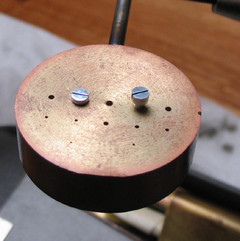
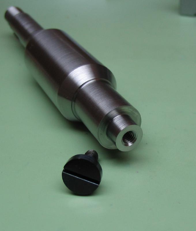
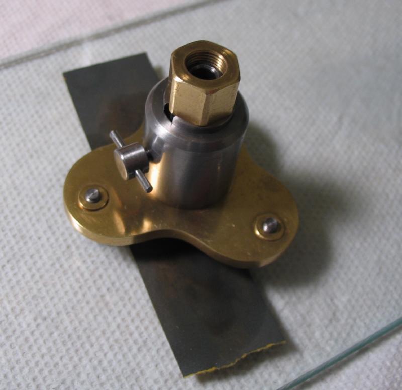
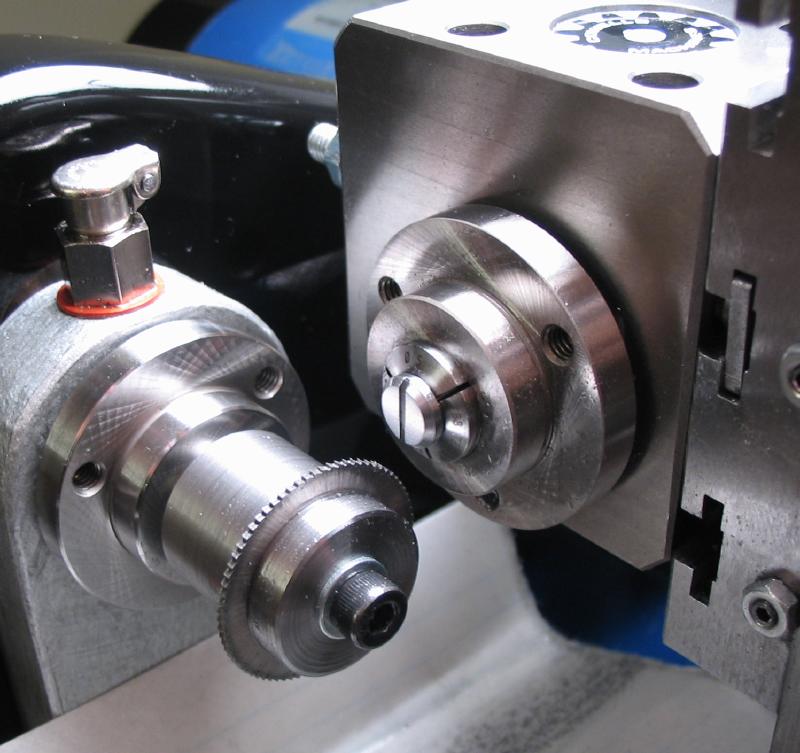
Collet Nut
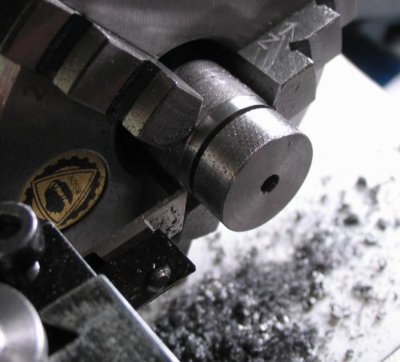
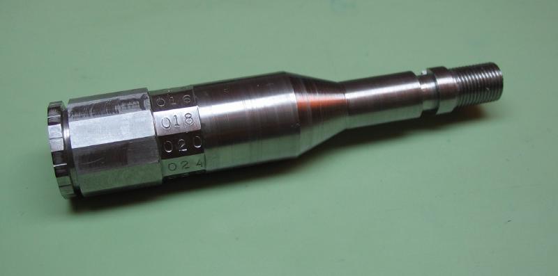
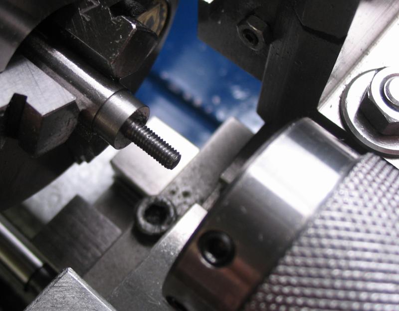
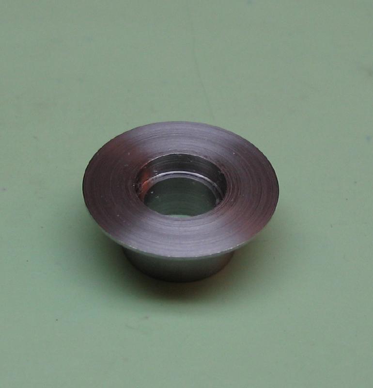
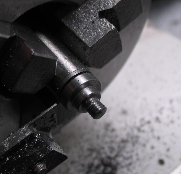
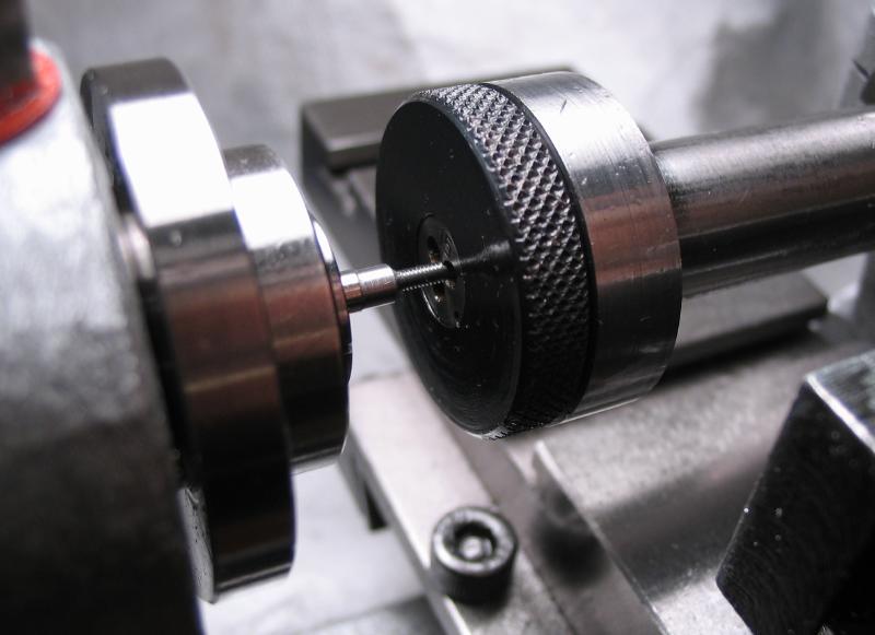
The collet is drawn-in by means of a simple nut. The nut was started from 5/8" 12L14 mild steel rod. While preparing a length of rod for another job, a little extra was added for making this nut. With the work held in the 3-jaw, with tailstock support and support from the steady rest; the rod was turned to 15.38mm (a calculated integer multiple (63) of the knurling tool tooth pitch). The knurling tool was mounted in the parting tool holder and fed into the work by various methods. Once again I've been stymied by the knurling process. This was perhaps my best effort, but not at all acceptable. The process left a textured surface to the rod, and I decided rather than waste the stock, I grooved it in 0.2mm increments with a 60 degree threading tool.
 |
 |
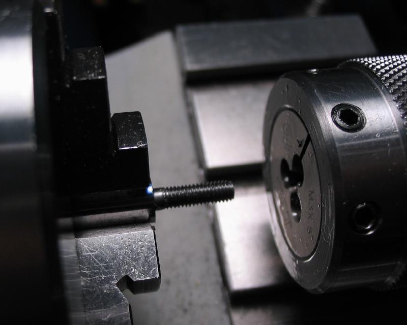
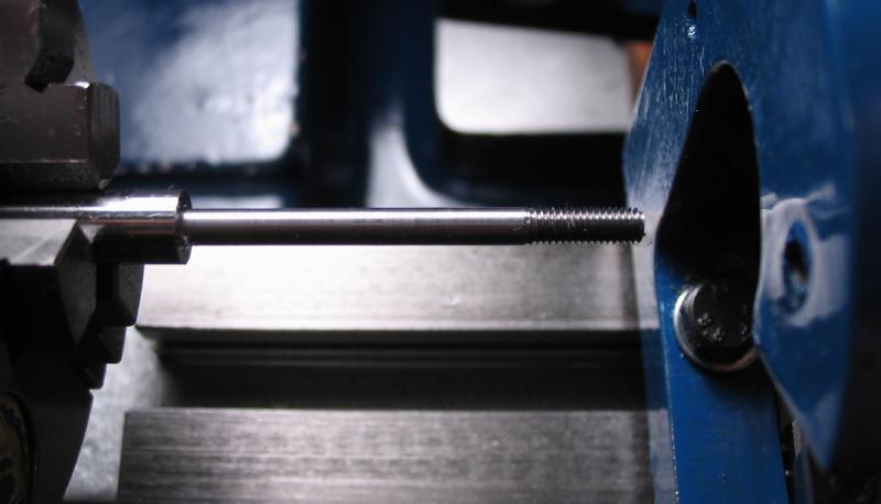
A length of the rod was parted off with enough material to hold in the chuck. The rod was then drilled 2.5mm and tapped M3x0.5. Following this, a 6mm section was parted off.
 |
 |
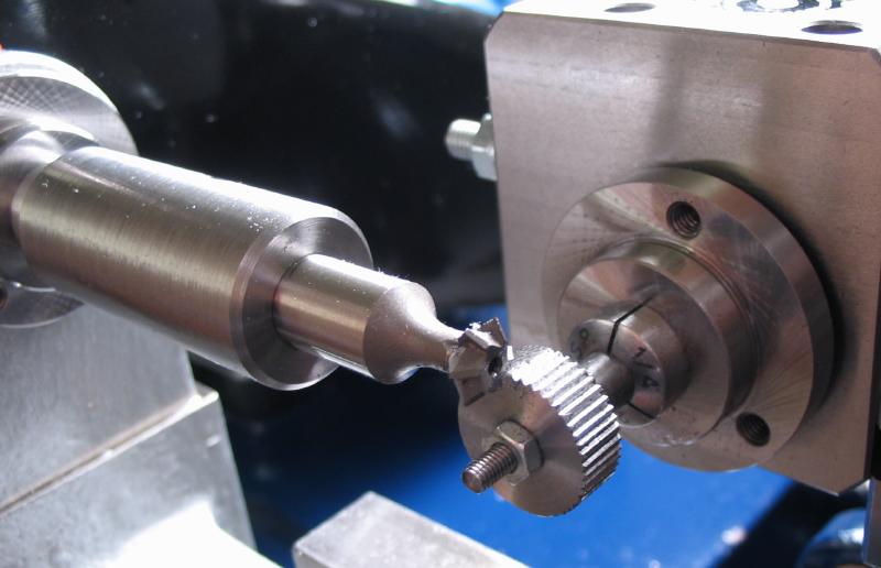
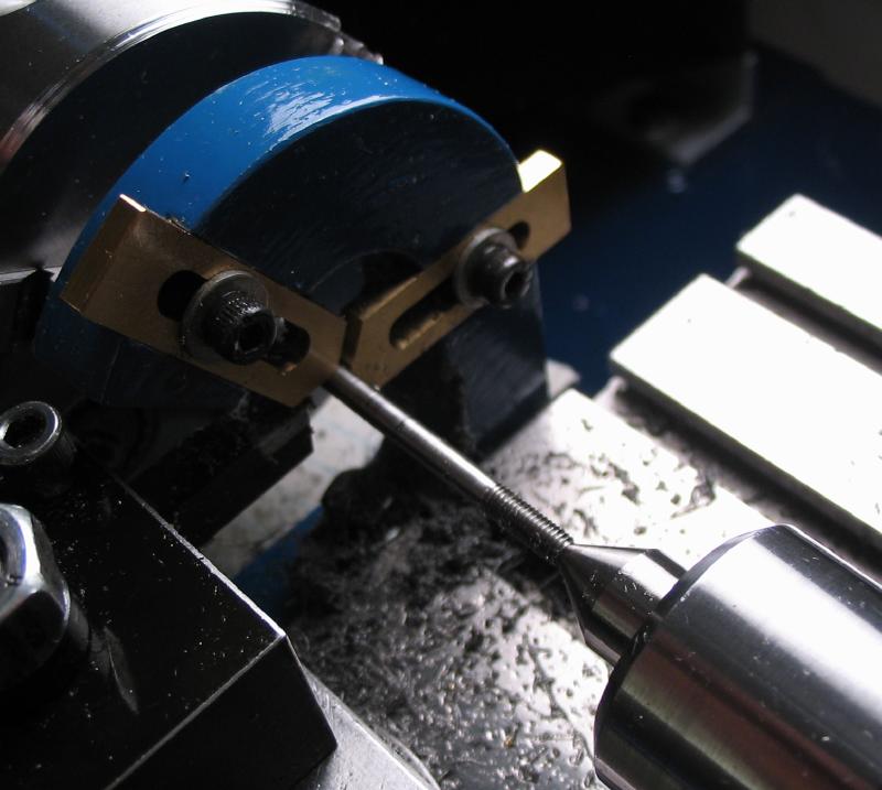
An arbor was made from 1/4" mild steel, turned and threaded M3x0.5 with a die. The parted collet nut was screwed onto the arbor and a hex nut used to secure it. This assembly was transferred to the dividing head. The 'D' plate was installed to provide an index circle count of 18; 8/9ths of a rotation will provide a total count of 45. A 90 degree double angle cutter was mounted in the headstock using the 3/8" endmill holder. Cuts were made at a depth of 0.25mm.
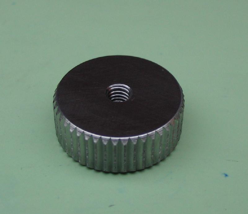
The nut/arbor/collet assembly is moved to the headstock. The compound slide is used to chamfer the edges. It can then be finished on emery paper to smooth the faces.
 |
 |
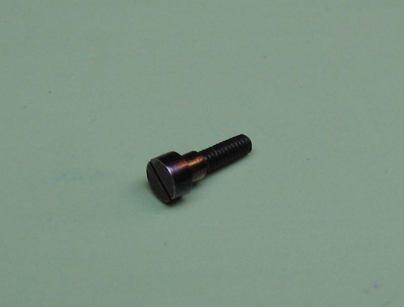
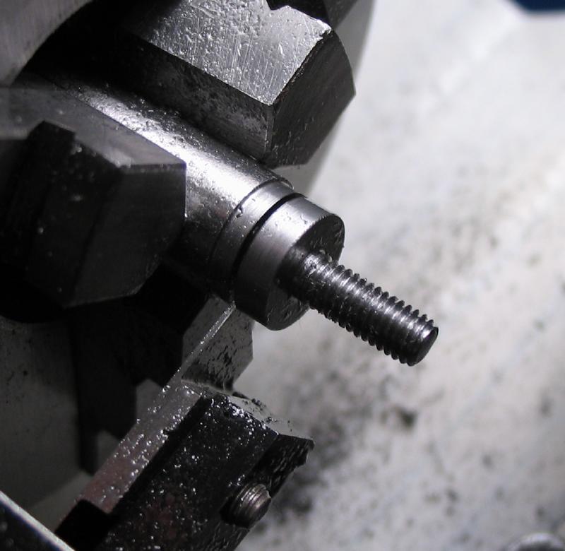
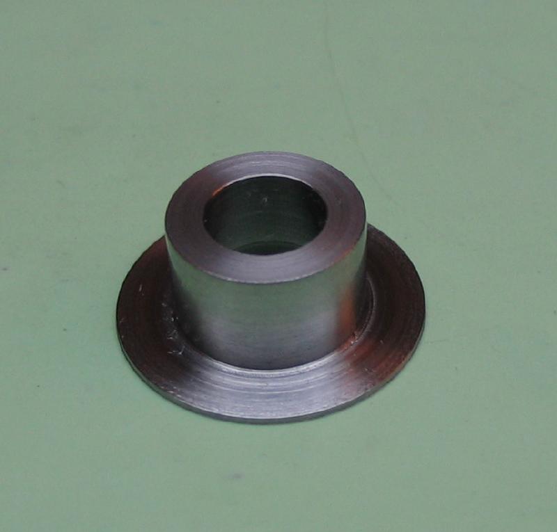
The arbor used to hold the collet nut was planned as the start of the next component. Recall it is 1/4" 12L14 mild steel turned and threaded for M3x0.5. It will become the securing screw for the retainer bearing.

The work is moved to the divding head and the plain portion was milled with the 90 degree double angle cutter to a final depth of 0.4mm and indexed through 20 steps (18 degrees).
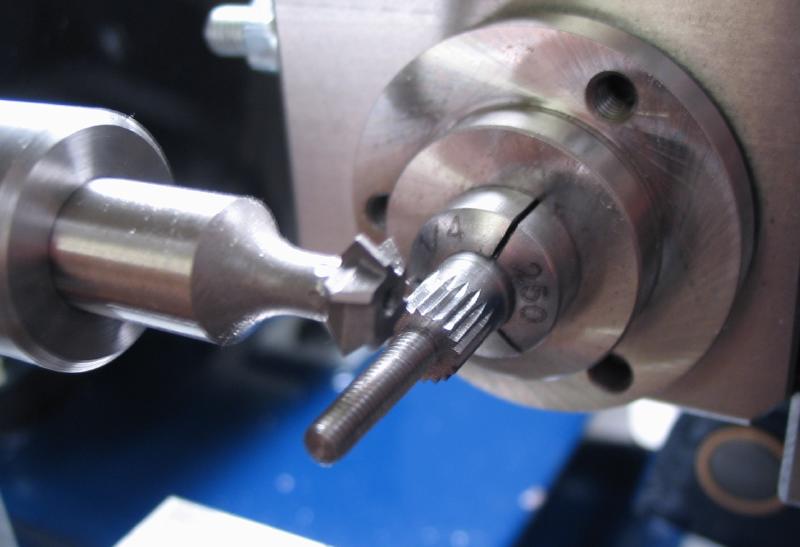
The threads were shortned to 8mm in length, and the screw is parted.
 |
 |
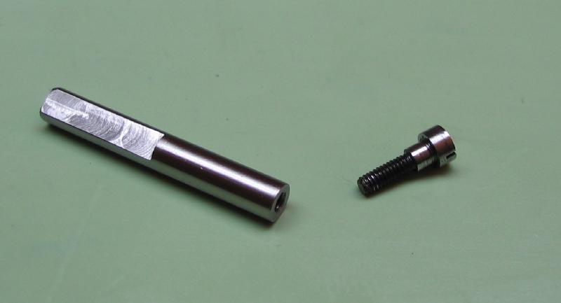
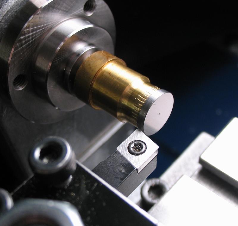
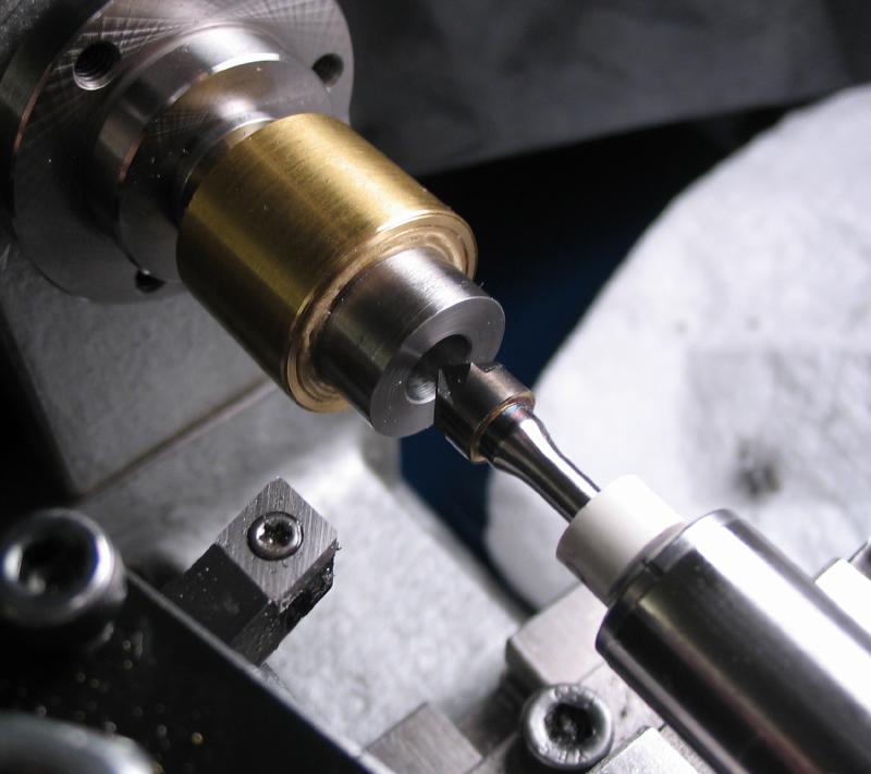
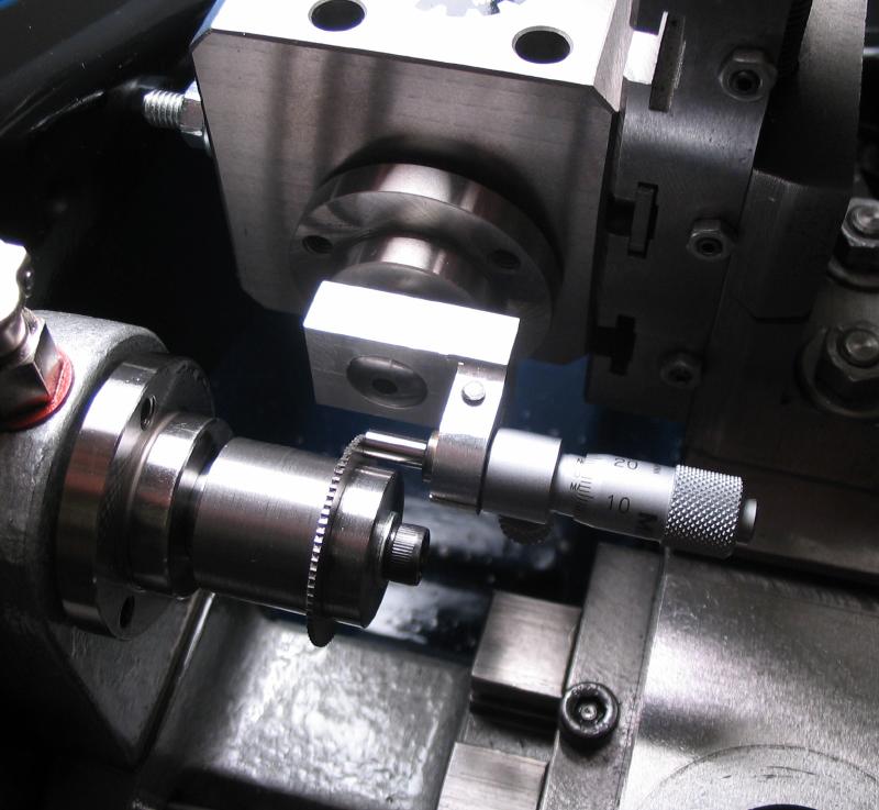
Collet Spindle
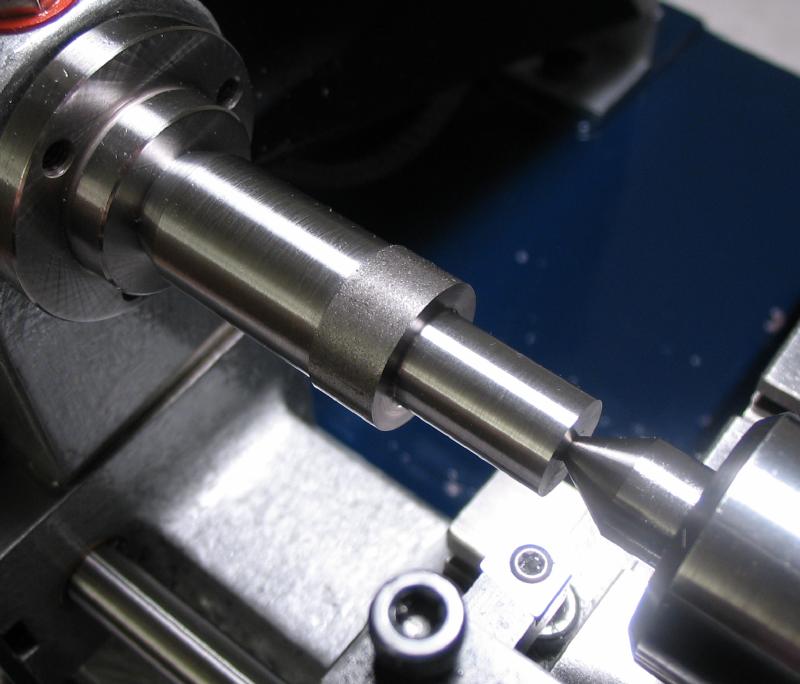
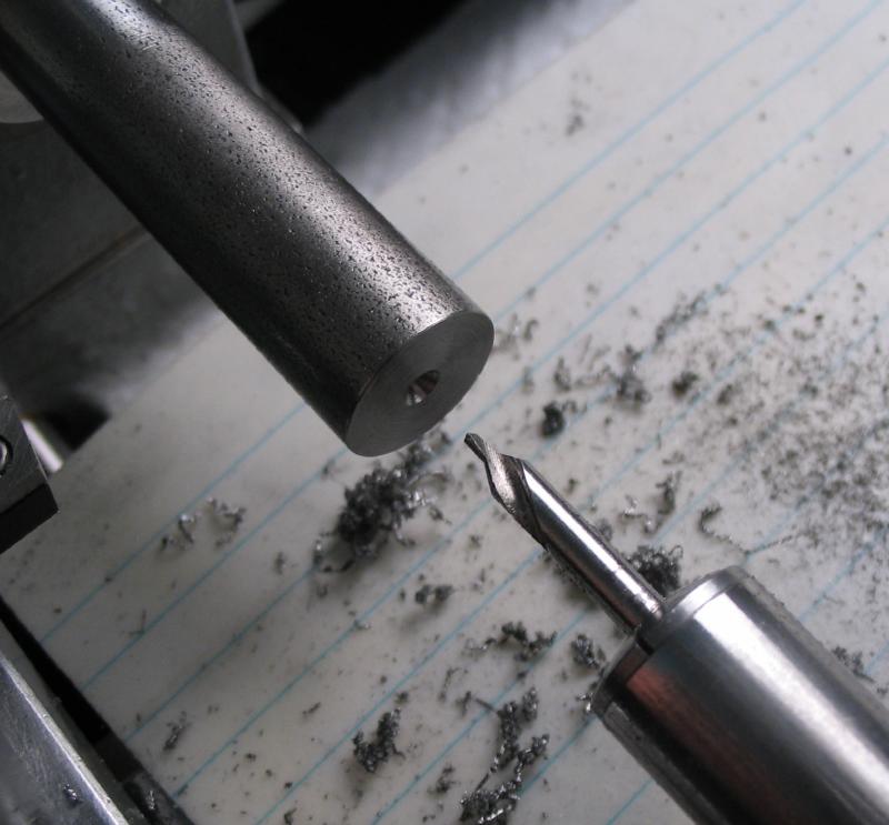
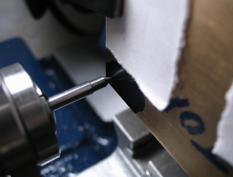
The spindle is made from 1/4" O-1 drill rod. A length is faced and center drilled on each end.
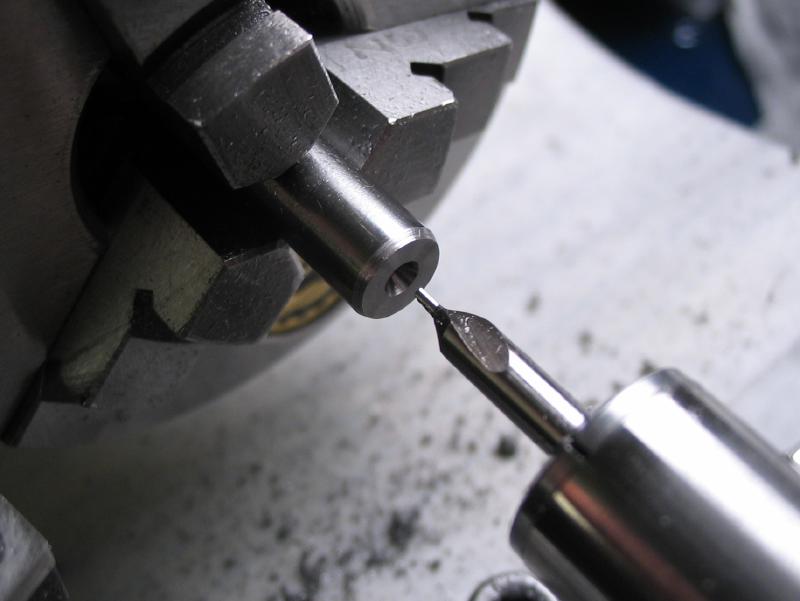
The rod can now be mounted between centers. The mounting portion of 5.00mm and the bearing surface of 6.00mm are turned. These two diameters should be concentric and accurate. These surfaces mate with reamed holes, and therefore must be accurately turned.
 |
 |
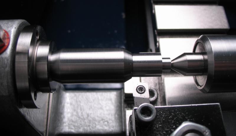
The work can be tried for fit and returned to the lathe. To do this it must be mounted between centers.
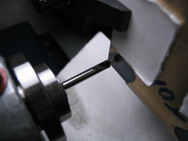
The final length was measured with the leadscrew and the parting tool used to start the cut. However parting should not be done between centers. It was secured in the 3-jaw and parted.
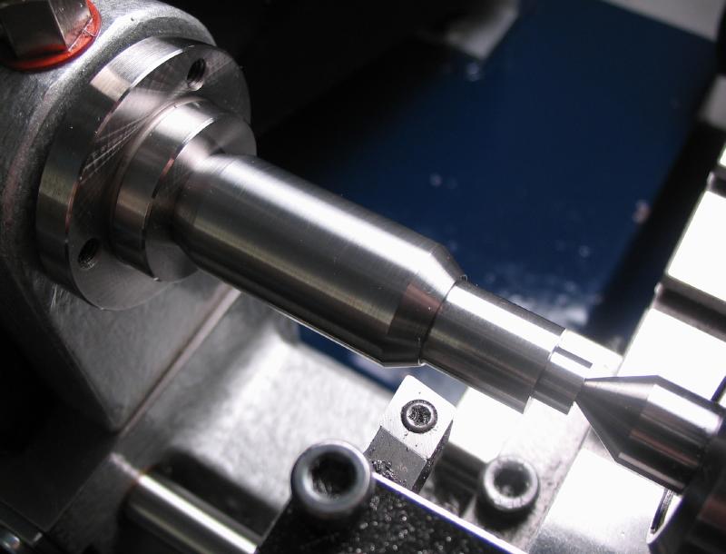
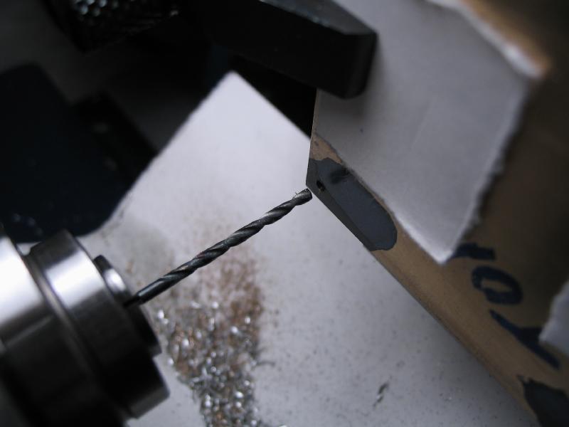
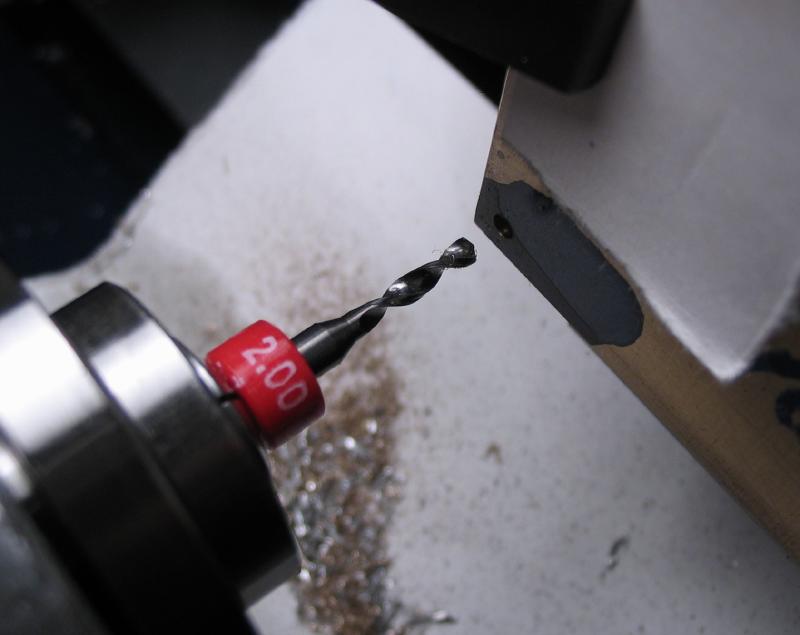
The parted spindle is swapped back into the 3-Jaw chuck, and drilled axially with a 2.90mm drill.
The compound slide and boring bar were used to turn the collet spigot surface at 20 degrees.
 |
 |
 |
 |
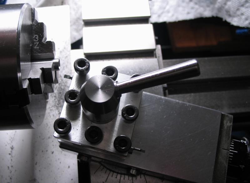
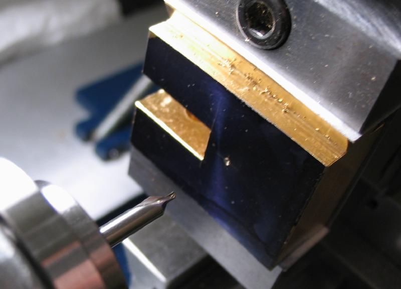
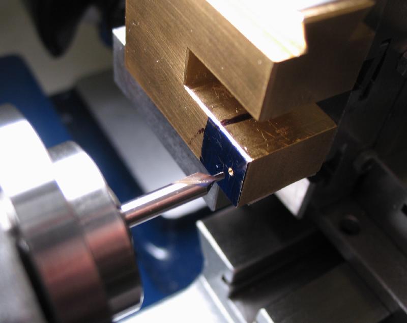
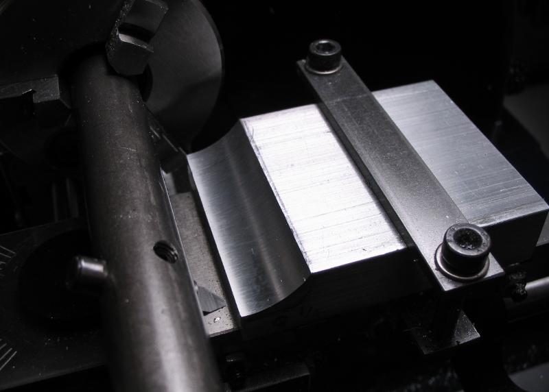
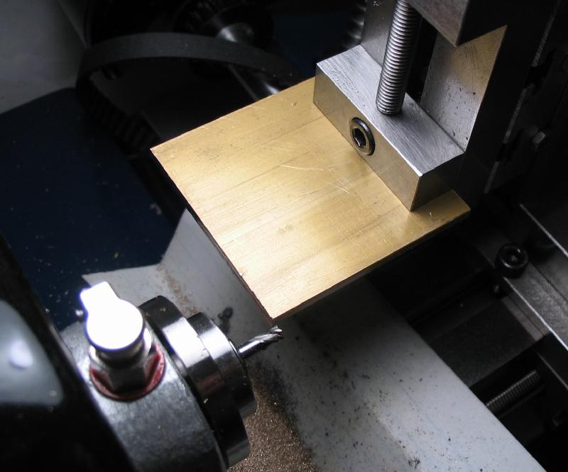
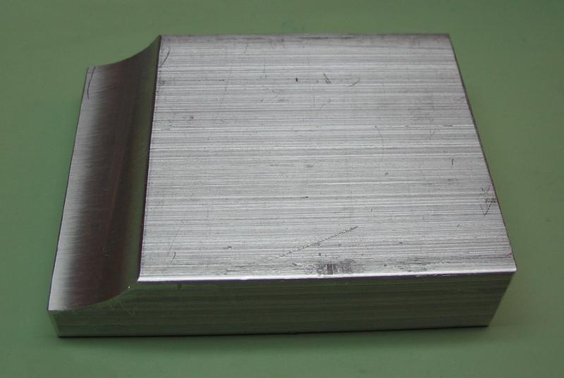
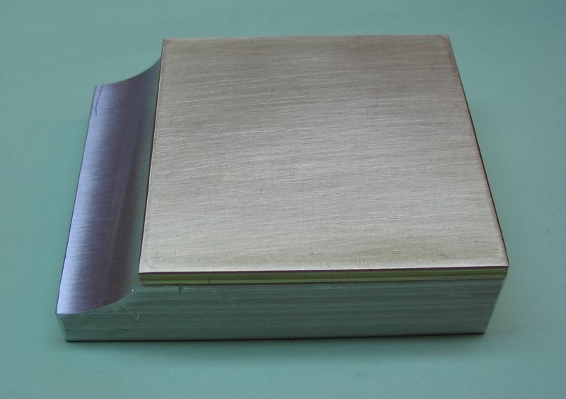
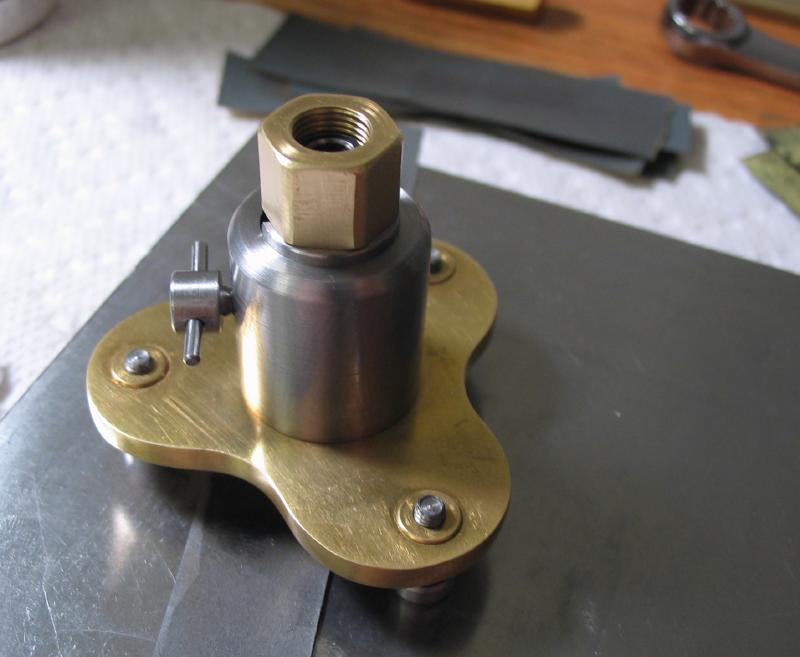
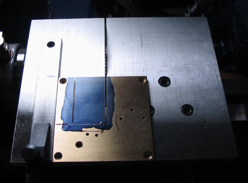
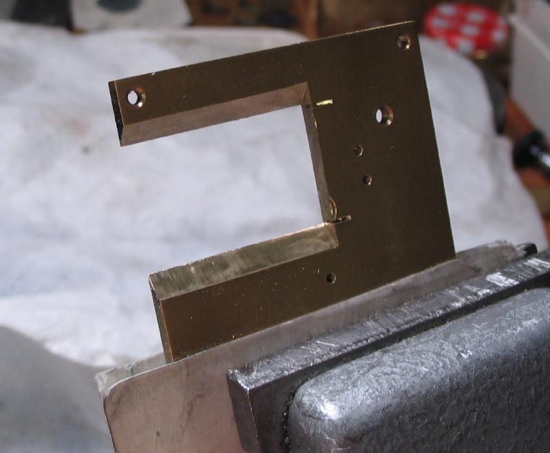
Mounting Block
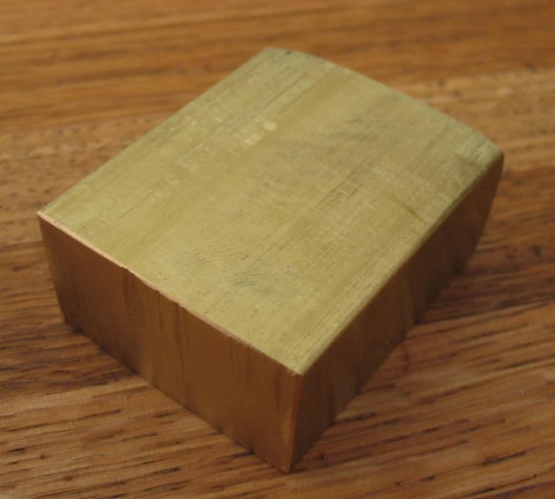
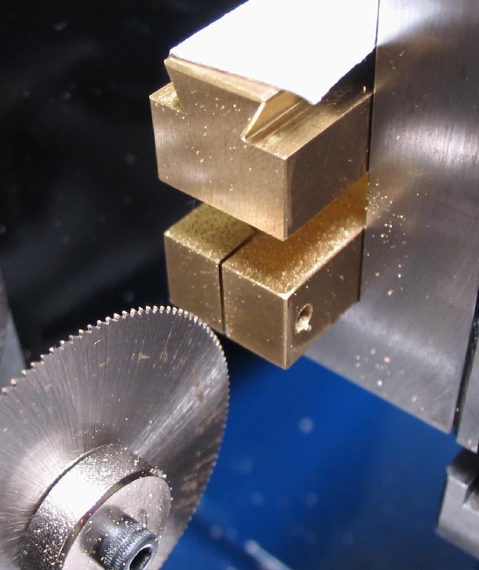
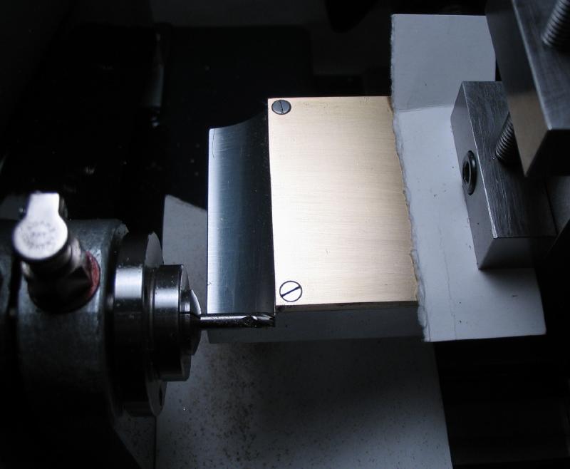
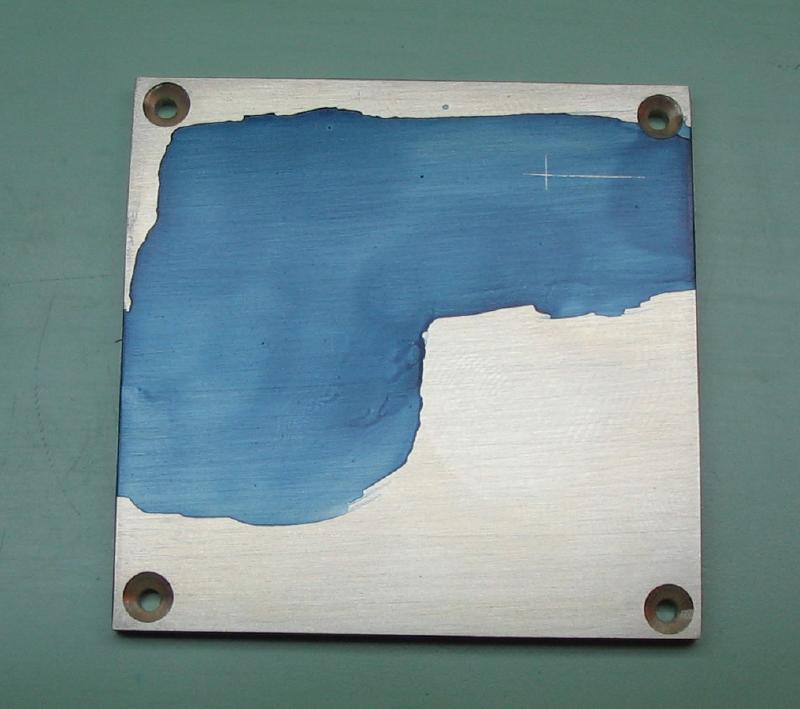
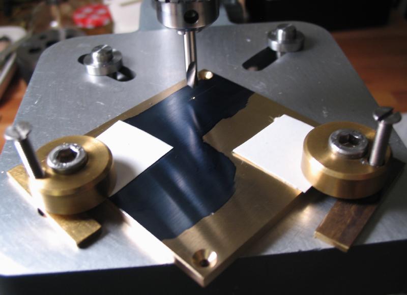
I wasn't sure what to call this part, it is the mounting upon which many of these components are attached. It is started from a 1.5" length of 1.25" x 5/8" brass bar (type 360). The condition of the stock is rather rough, and must be machined on all surfaces to make it "square". This was done with the 4-jaw chuck and facing cuts on each surface.
 |
 |
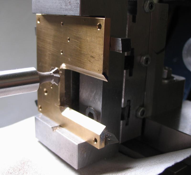
The block will mate with the headstock clamp, and therefore provide a means of adjustment for position. The block is mounted in the toolmakers vise and on the vertical slide. A 3mm endmill was used to form the major dimensions of the dovetail on each side of the block.
The dovetail is finished using the same 60 degree dovetail cutter used to machine the headstock clamp above.
 |
 |
 |
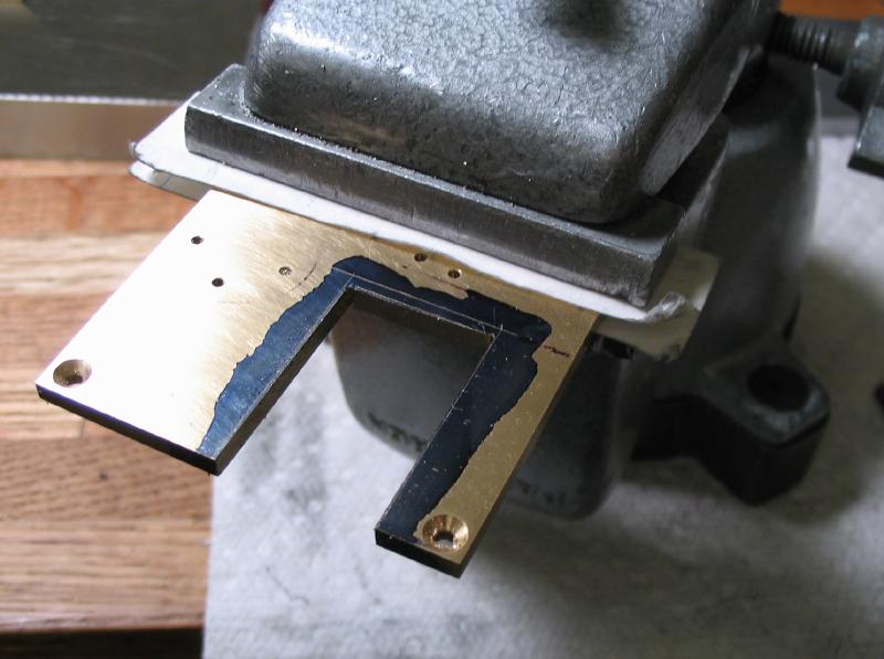
The work is hand fit to the clamp using a barrette file to make small adjustments.

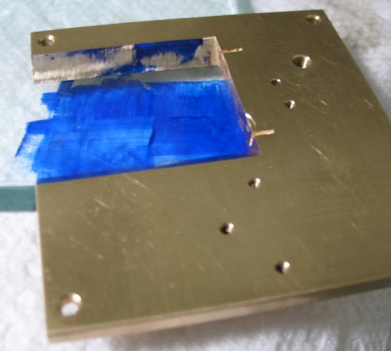
The slot for the collet nut is milled using a 1/4" endmill.
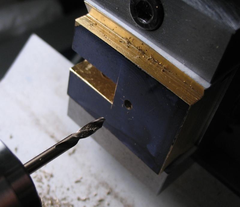
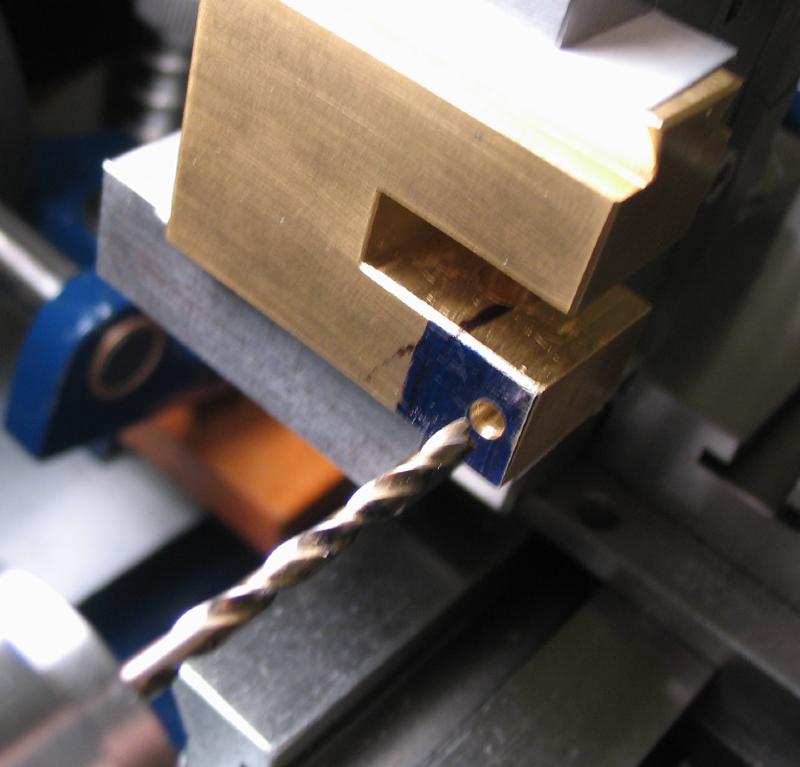
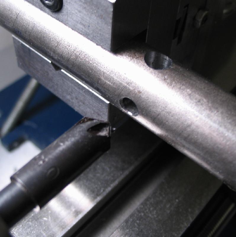
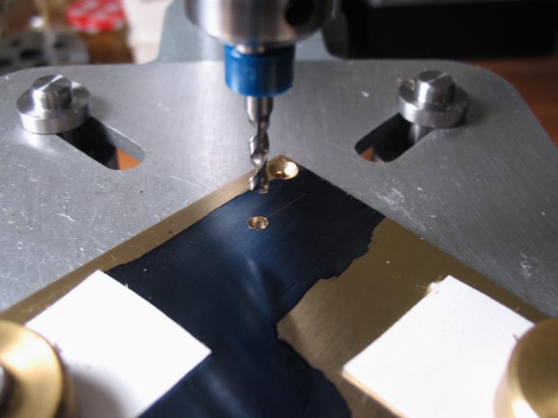
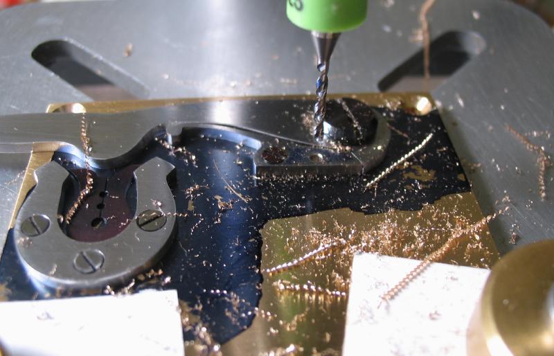
The positions for the collet spindle and retainer are laid out, and the mount returned to the vice for drilling, and reaming to the respective diameters.
 |
 |
 |
 |
 |
 |
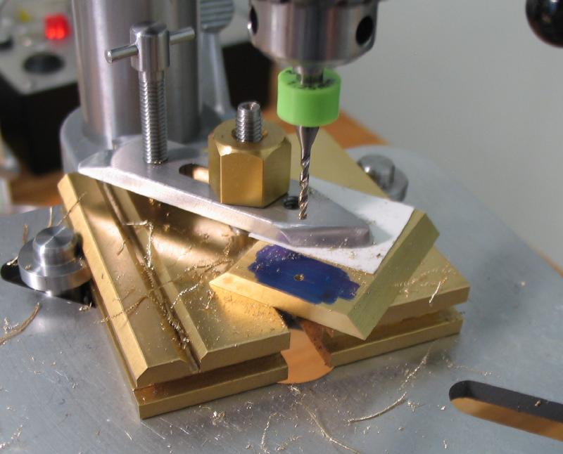
The position for the locking screw is center drilled and drilled 2.50mm for tapping M3x0.5.
 |
 |
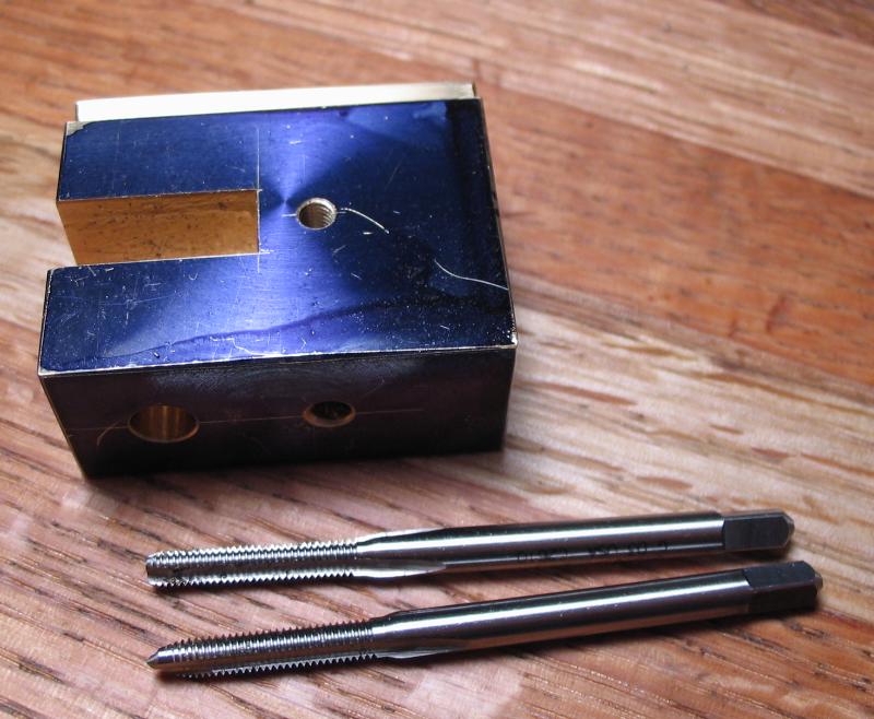 |
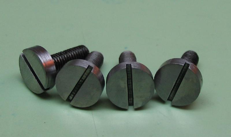
Spindle locking screw
The spindle is a tight fit with the reamed hole in the mounting block. However, a locking screw is made to secure the spindle from accidental movement
The screw is made from 5mm O-1 drill rod. Turned and threaded M3x0.5 and parted.
The screw is made from 5mm O-1 drill rod. Turned and threaded M3x0.5 and parted.
 |
 |
The screwhead is slotted 0.014".
 |
 |
The position for the screw is center drilled and drilled through 2.50mm.
 |
 |
The block is set up for slotting with a 0.014" slitting saw.
The bottom half the slotted portion is drilled 1/8" and the top half tapped M3x0.5.
 |
 |
The block is counterbored to accept the screw head. A counterbore was made from 5mm O-1 drill rod.
 |
 |
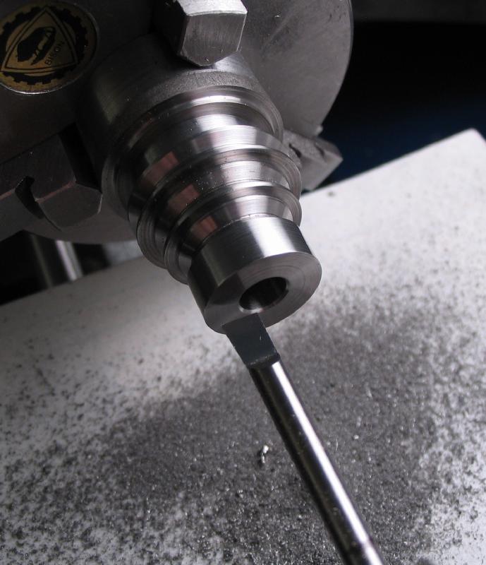
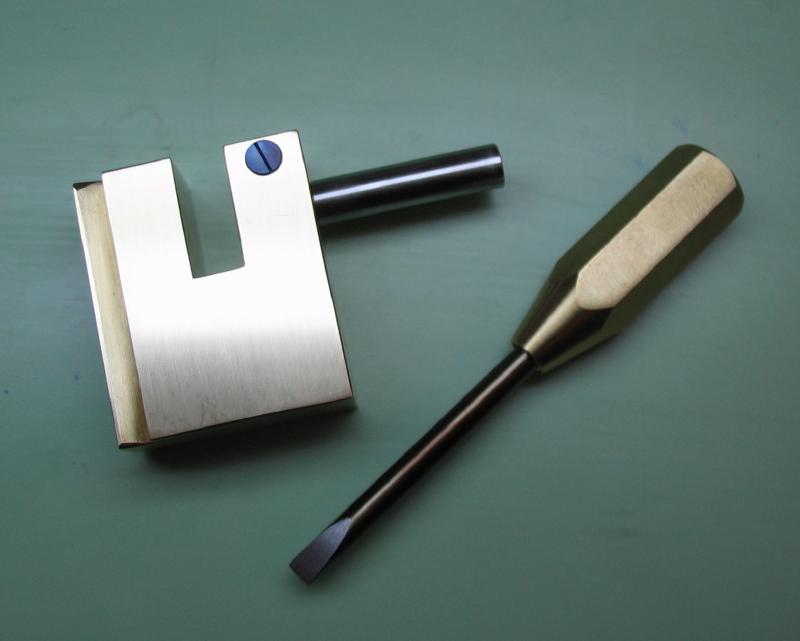
The locking screw was hardened in oil and tempered to a purple color. As it will eventually not need adjustment, it was left purple. As it happens, the screwdriver made previously works nicely....
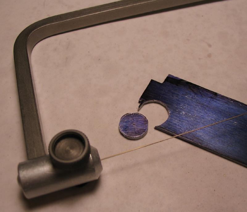
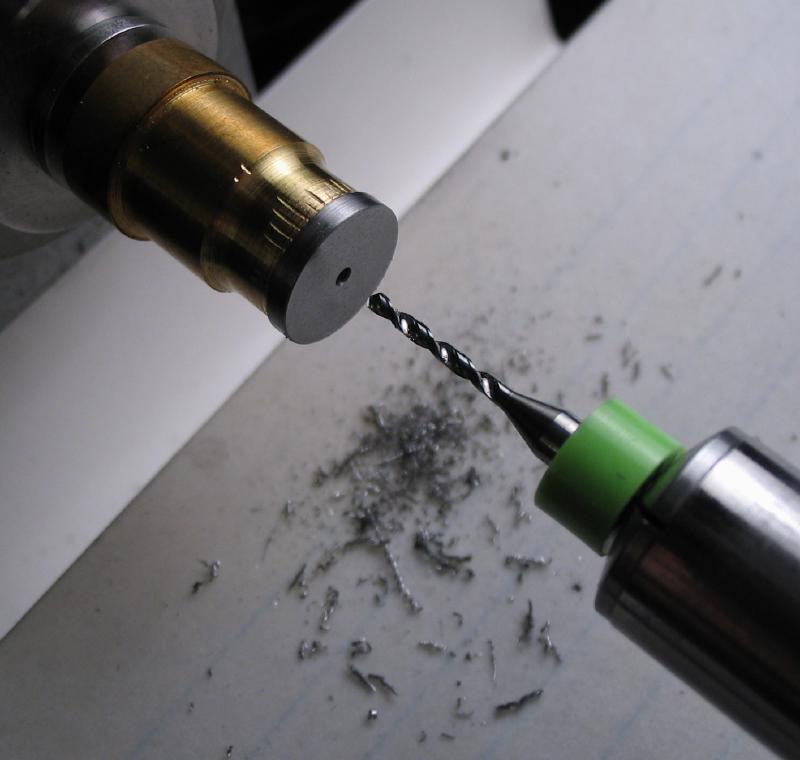
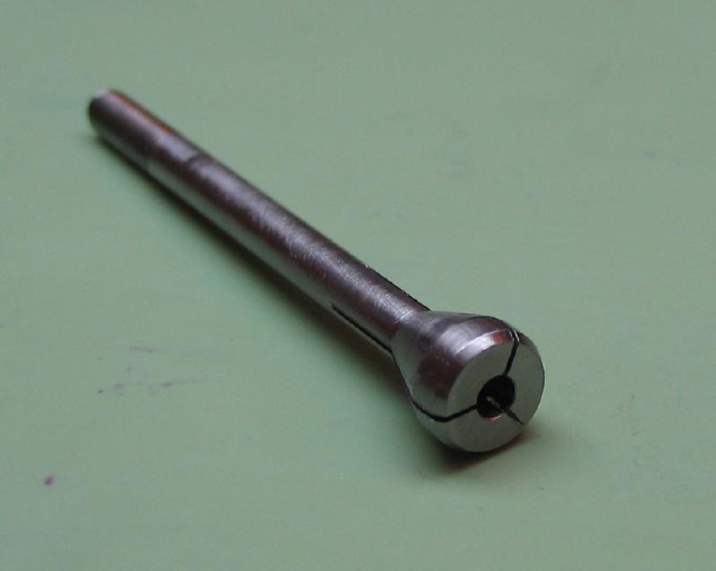
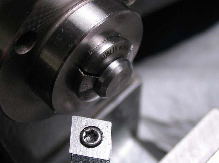
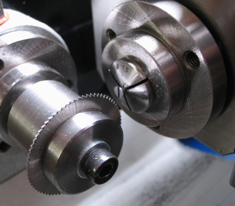
Collet
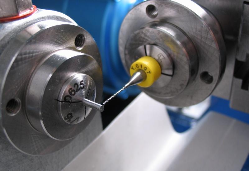
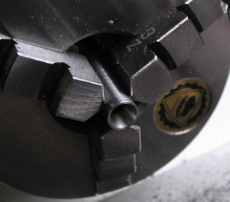
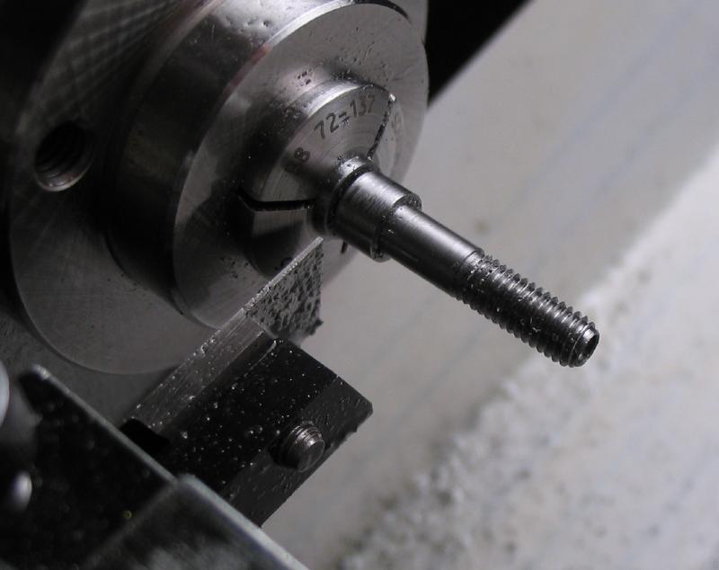
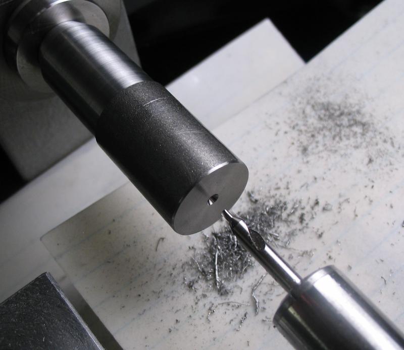
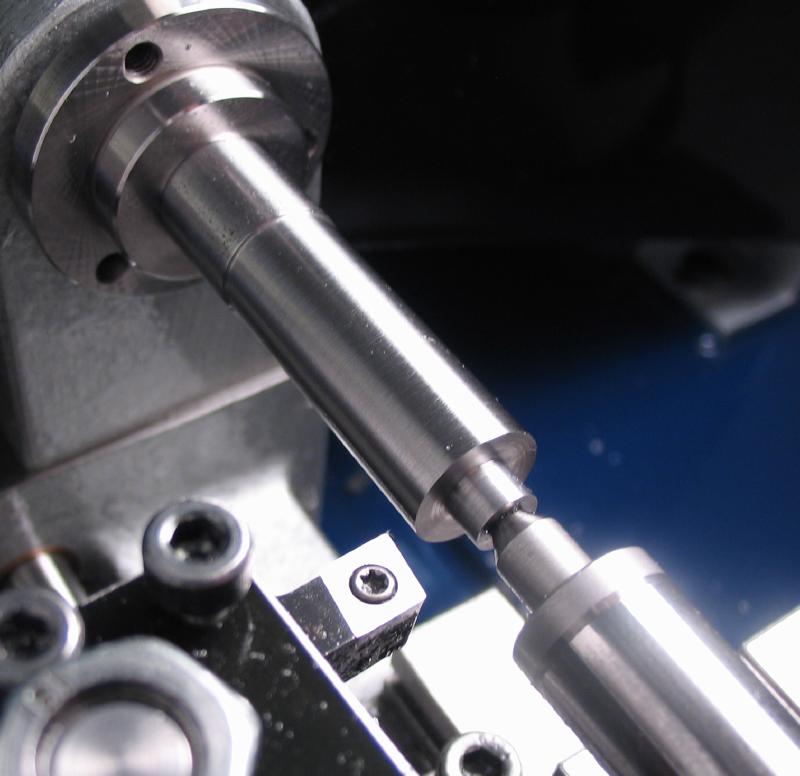
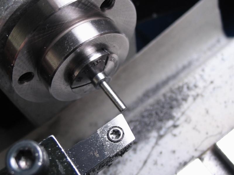
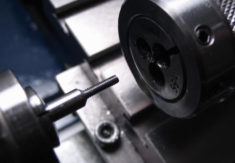
The collet was started from 6mm O-1 drill rod. It was faced and center drilled for center reference later on. The threaded portion was turned and threaded M3x0.5.
 |
 |
 |
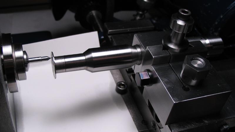
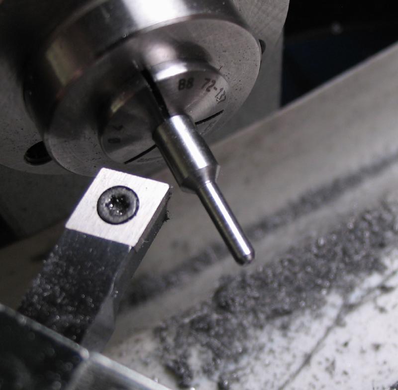
The body of the collet was turned to 3.0mm. To assist in turning a relatively long and thin diameter, the traveling steady was used. The traveling steady must be adjusted after each passing cut to account for the decrease in diameter, however, its use results in an excellent finish and uniform diameter throughout the length of the work (which is the point, of course).
 |
 |
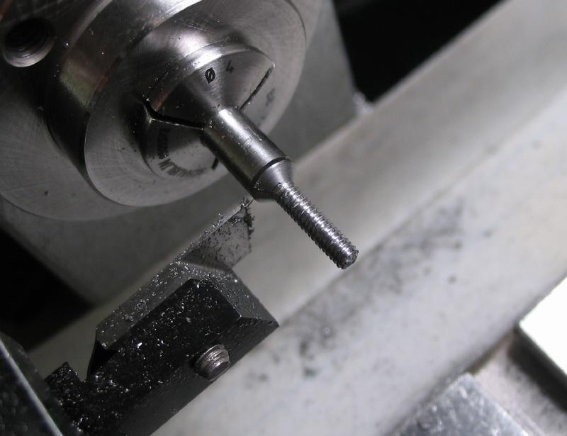
The taper for the collet head is turned using the top slide, set to 20 degrees.
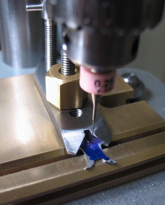
The unfinished collet is parted off.

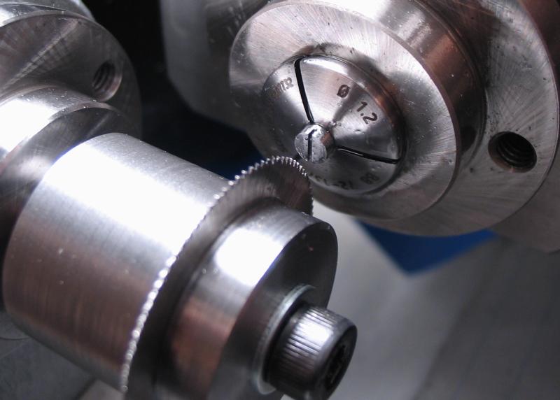
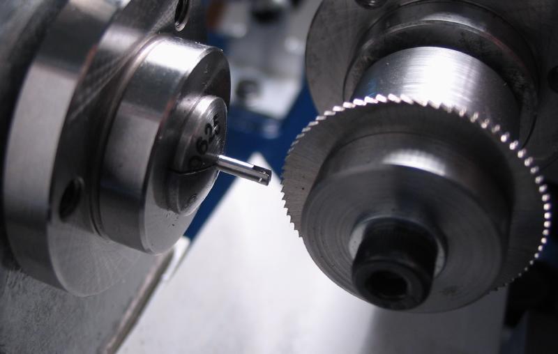
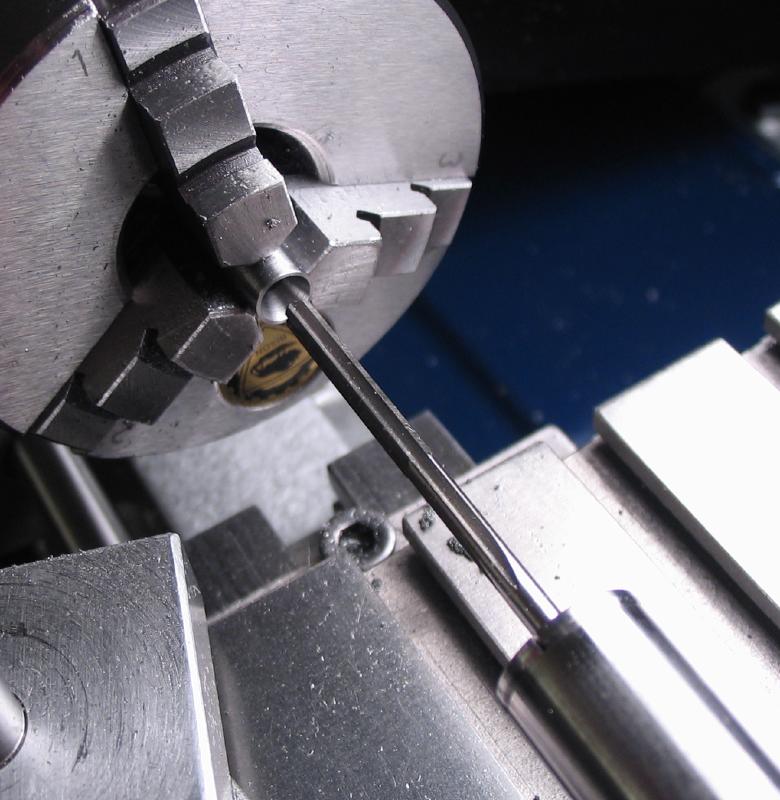
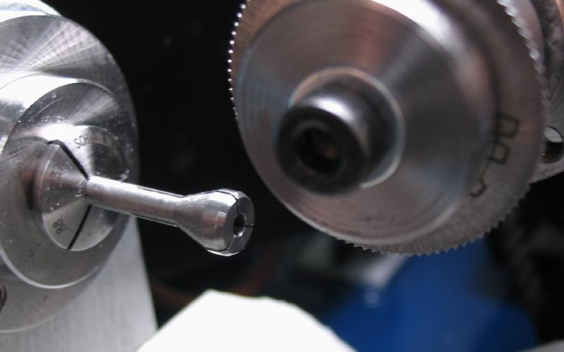
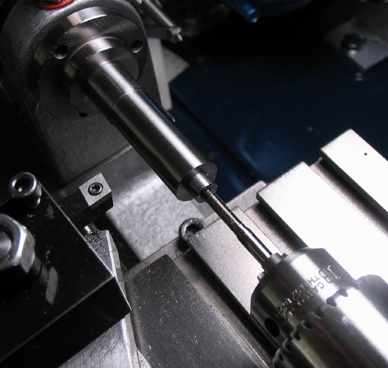
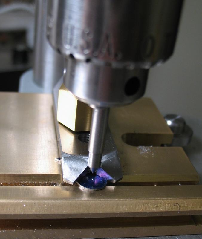
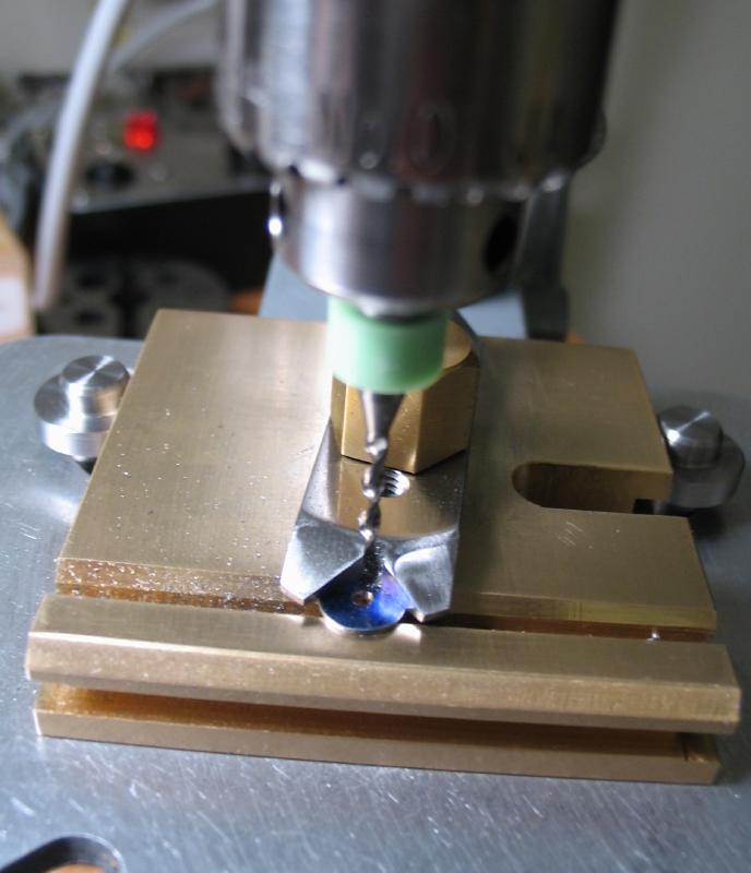
The collet is secured in a 3.0mm lathe collet and center drilled. The intended holding diameter of the turns collet is 2.0mm. It is drilled 1.95mm and then reamed 2.00mm.
 |
 |
 |
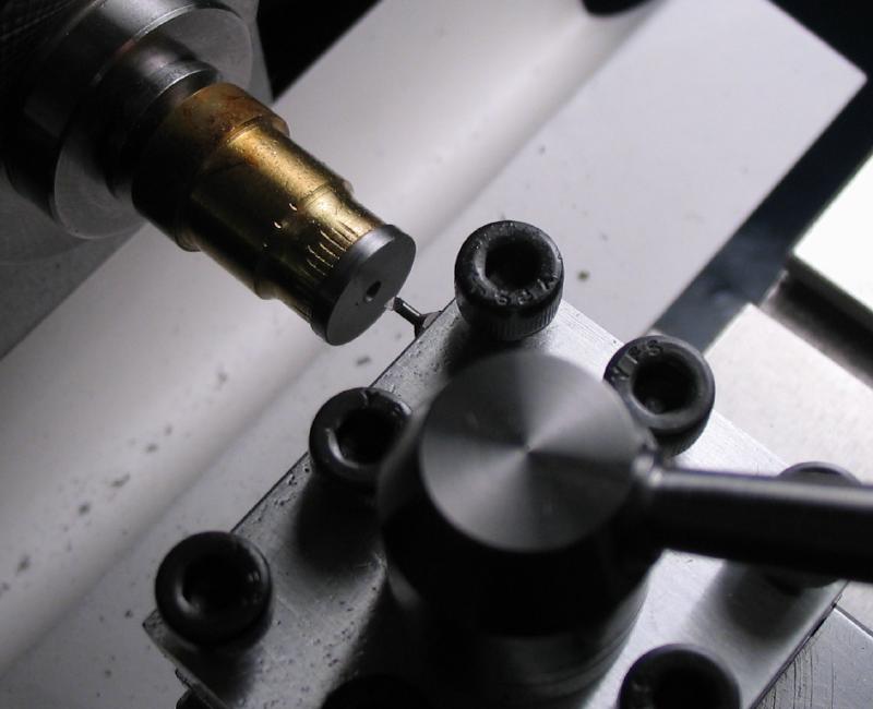
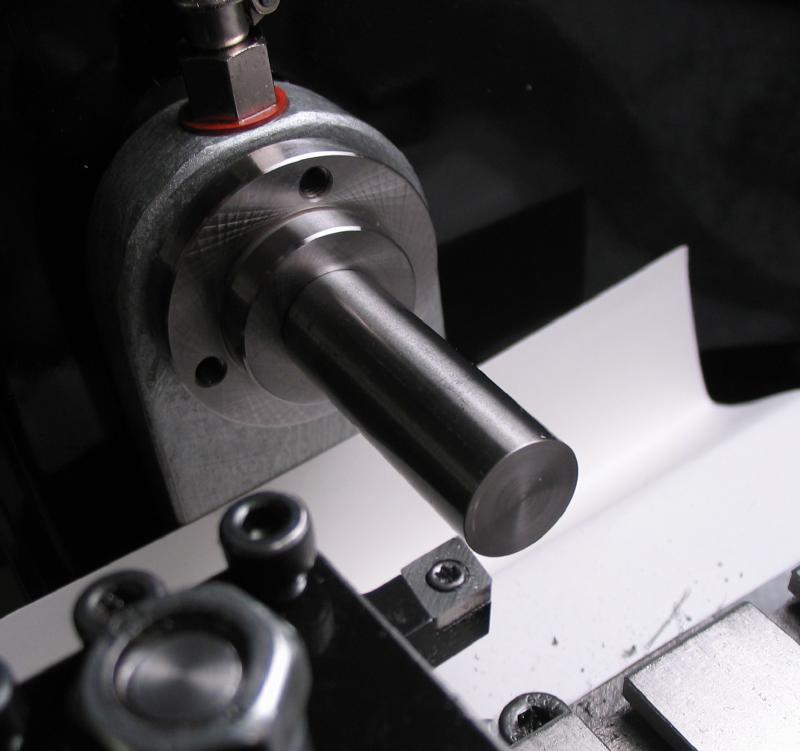
The headstock is locked and the collet slotted with a 0.008" slitting saw mounted in the milling spindle. The headstock is indexed through 120 degree steps.
 |
 |
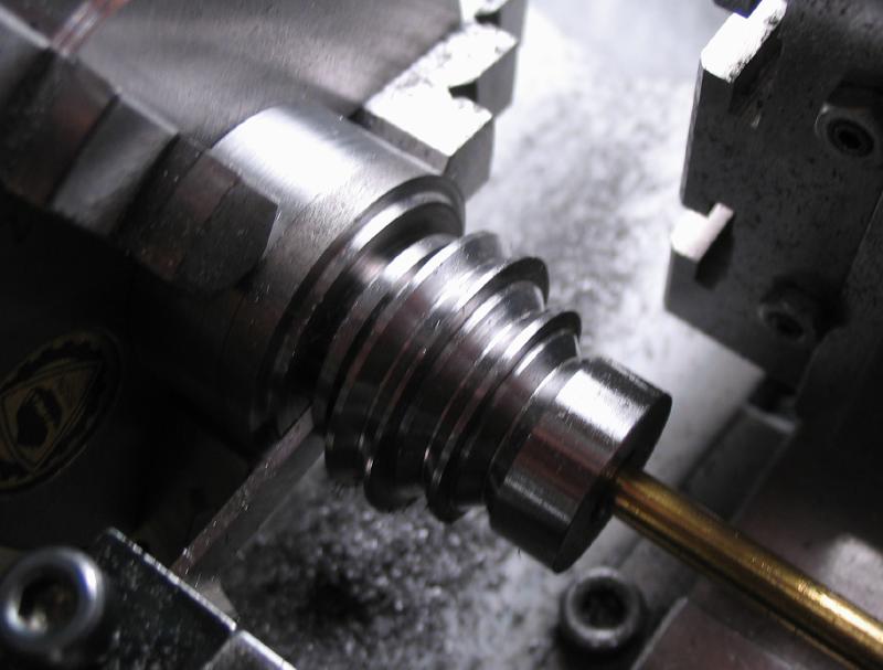
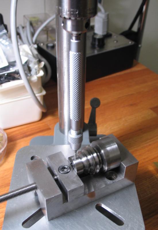
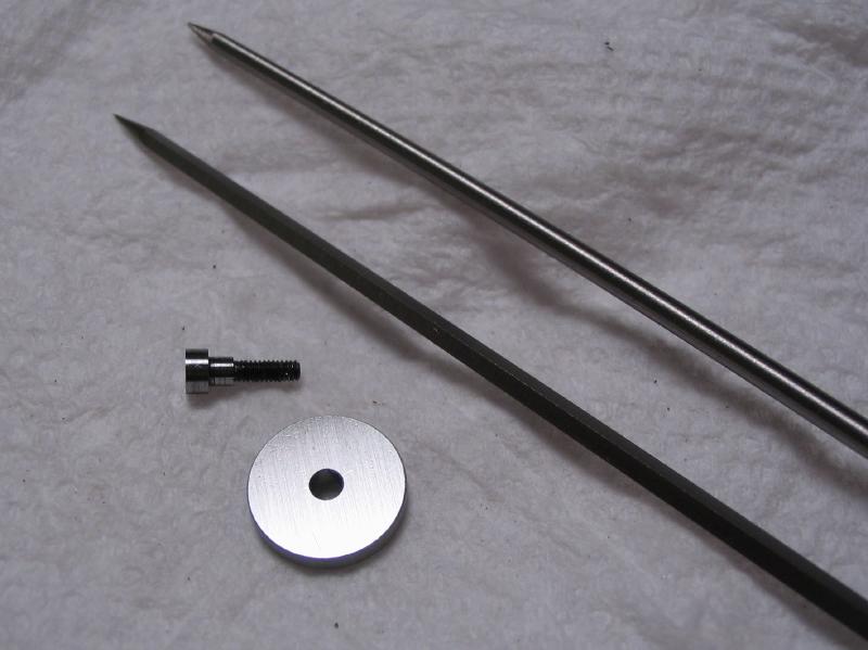
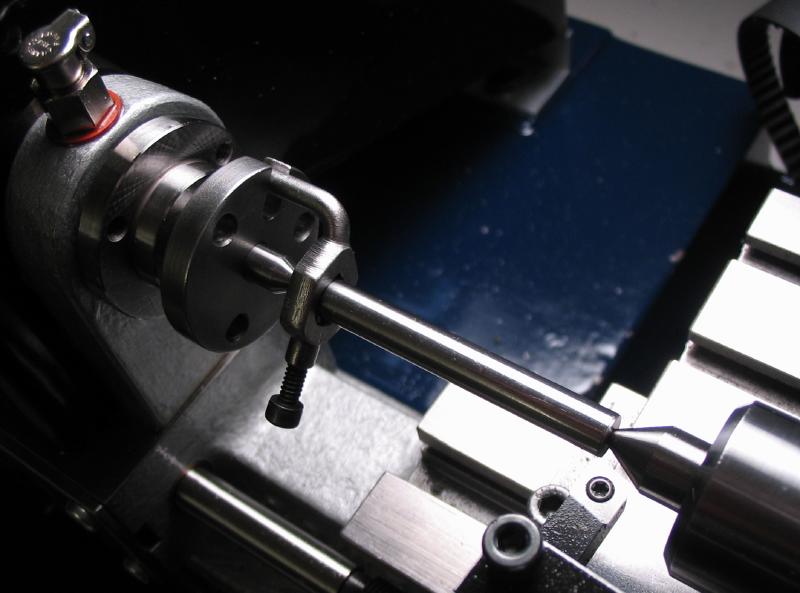
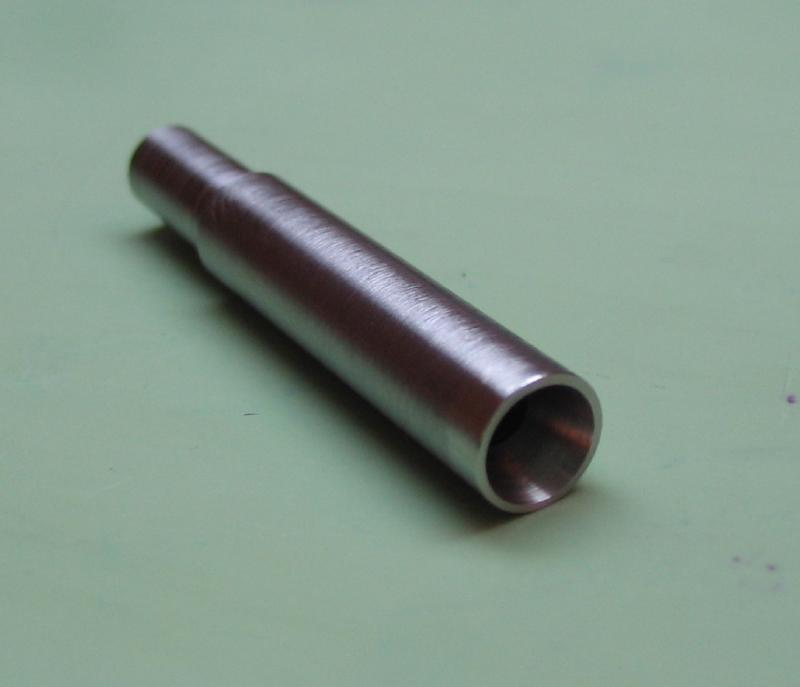
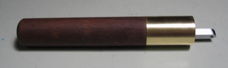
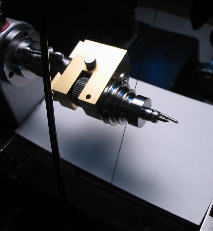
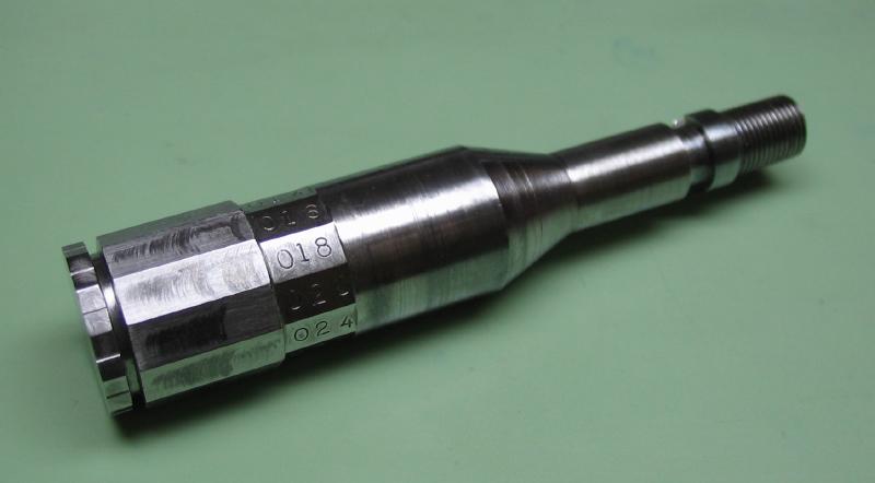
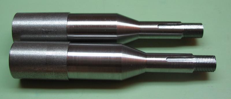
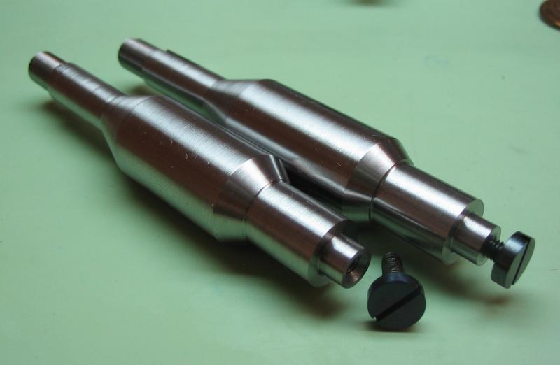
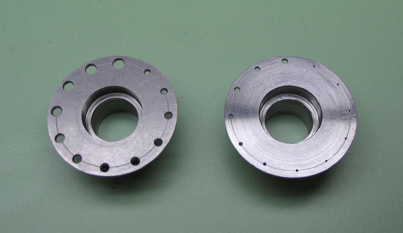
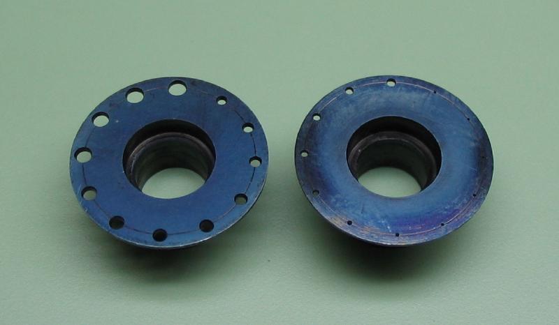
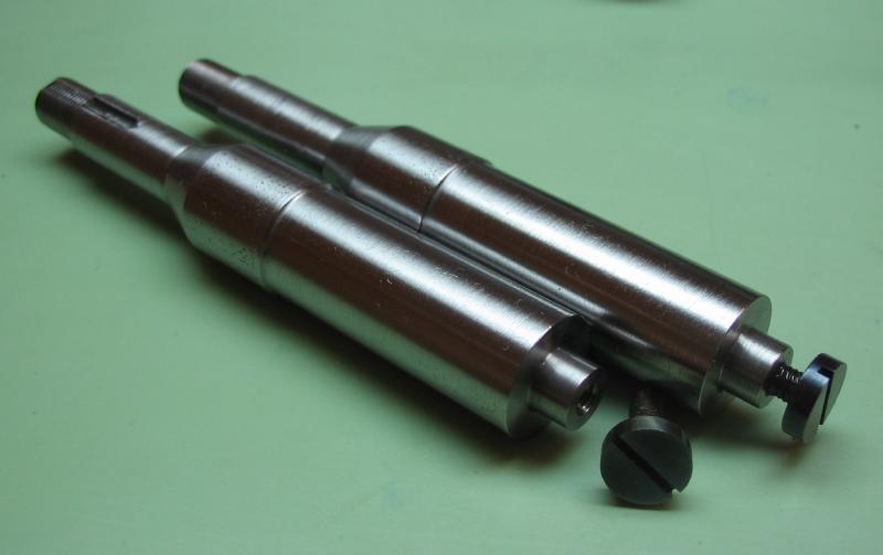
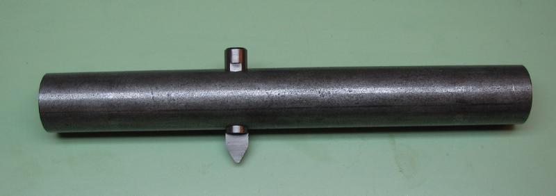
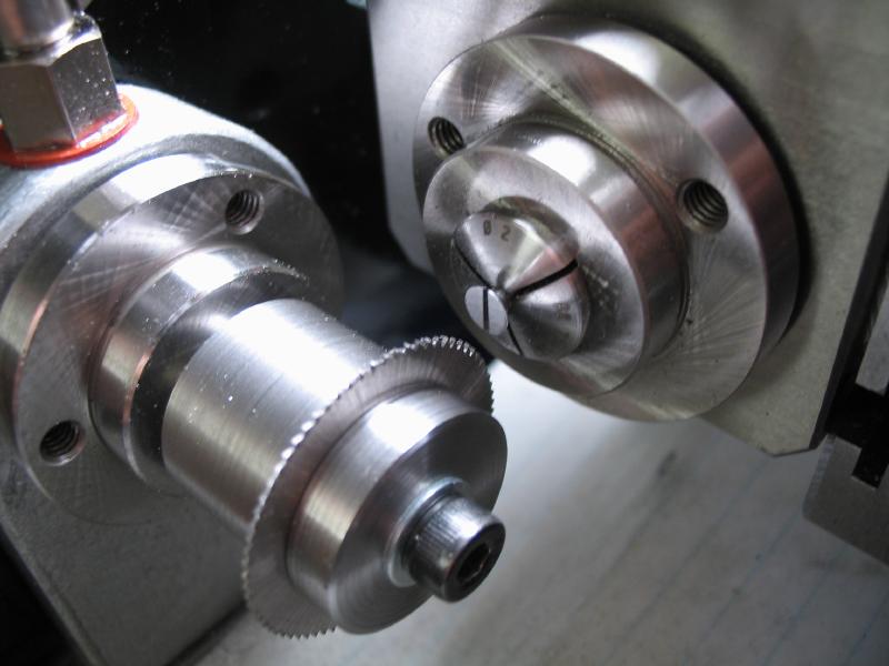
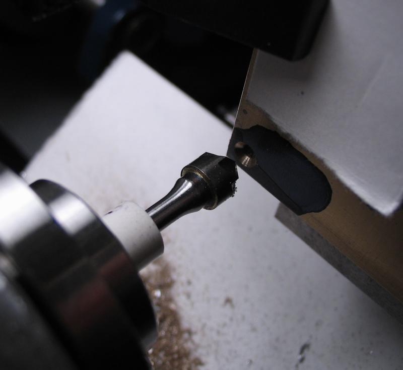
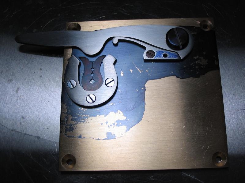
The completed headstock
|
|
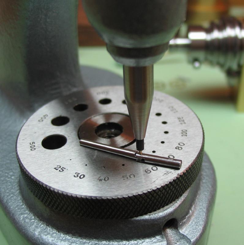
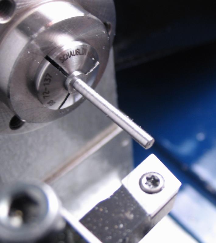
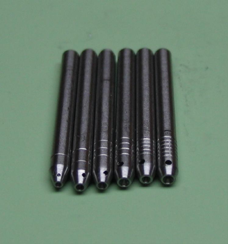
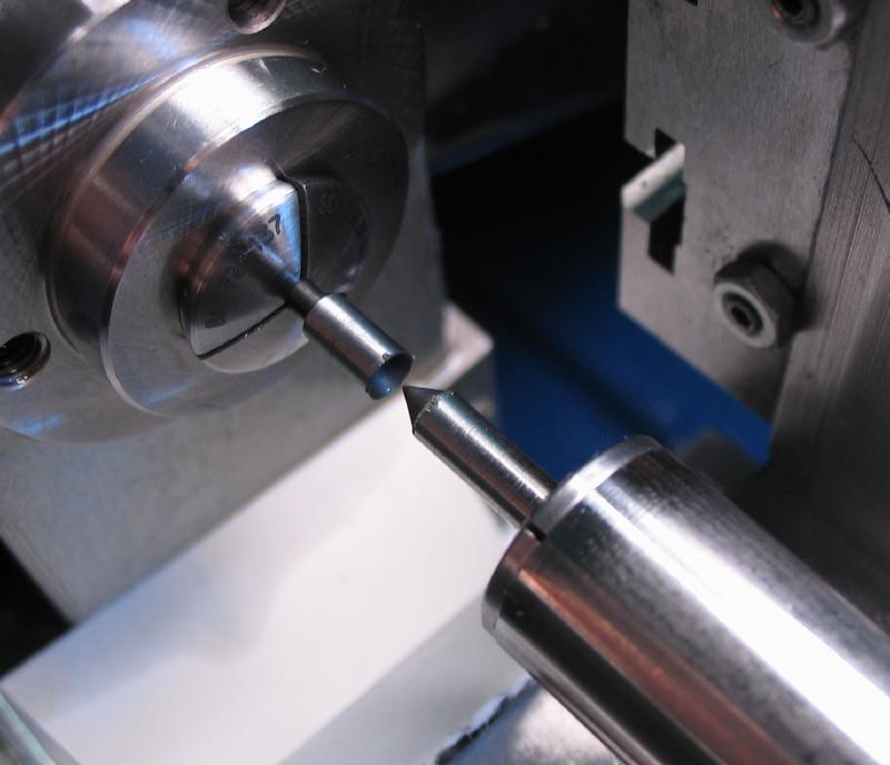
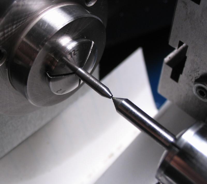
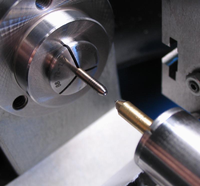
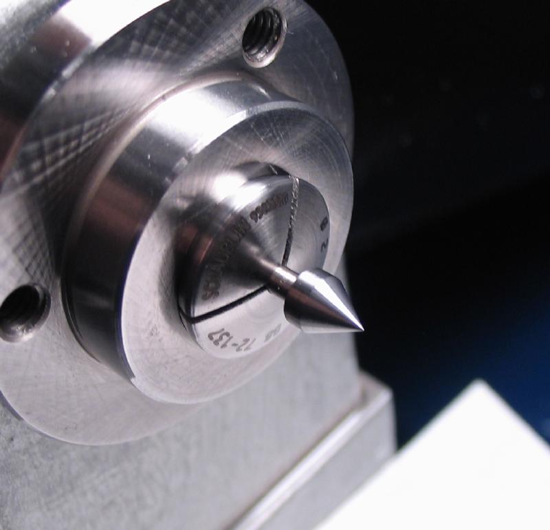
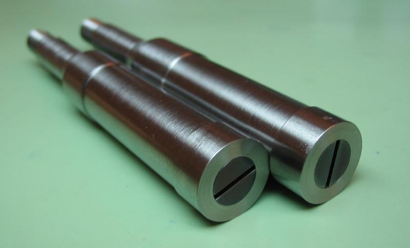
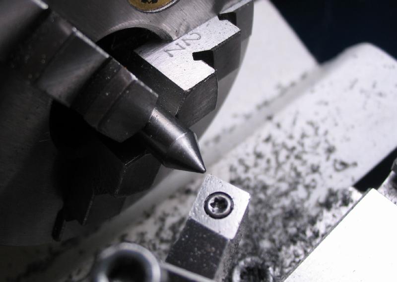
Centers / Arbors
A variety of centers can be made to fit the turns headstock collet. A batch of 2mm O-1 drill rod blanks were parted off.
Female centers can be made using standard combined center drill / countersinks
(i.e. Keo brand #5/0, #4/0, #3/0, #00, #0, and #1).
 |
 |
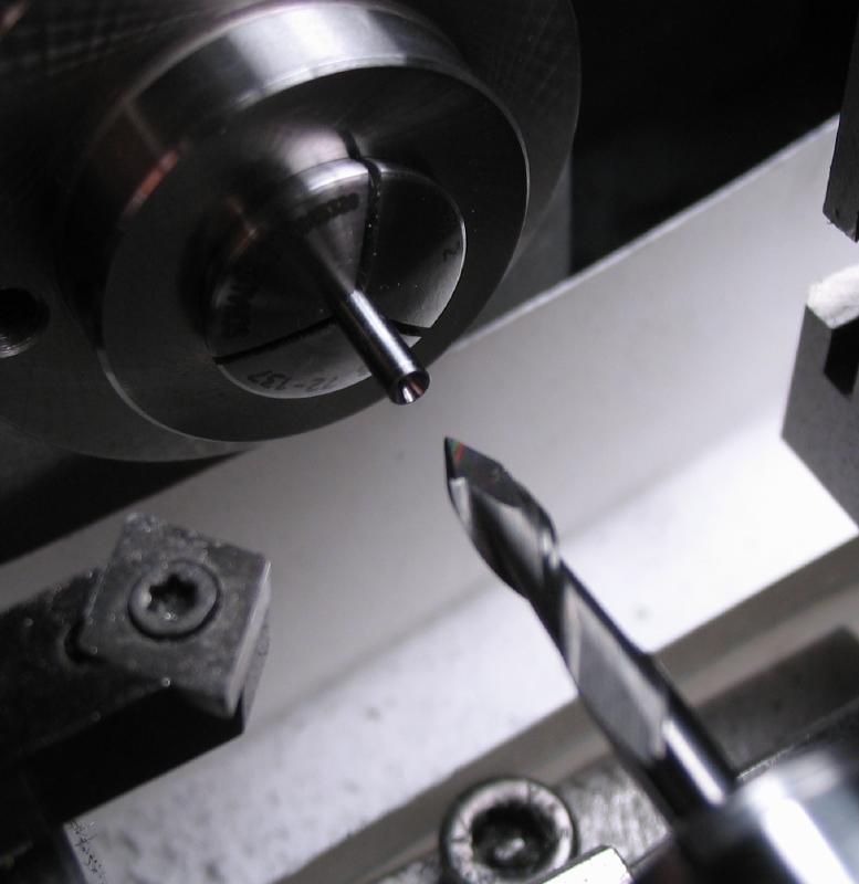
A set of 6 female centers were made by drilling (0.15, 0.20, 0.25, 0.35, 0.40, and 0.50). The end is taper turned 40 degrees. The hole is then countersunk 60 degrees using a 60 degree drill point endmill. Perhaps being an unusual bit, this one is a Melin AMG-402-DP60.
|
|
|

|
|
| Melin drill point endmills |
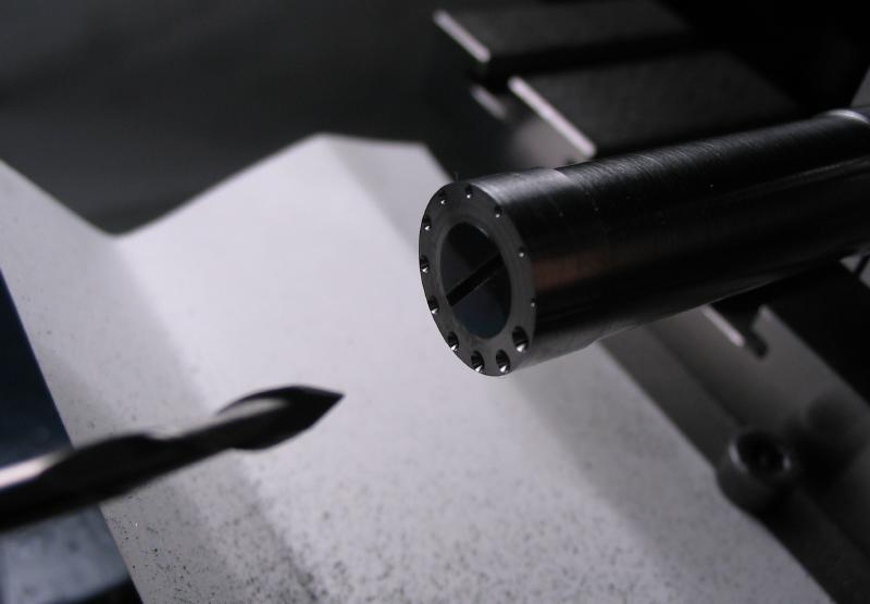
Another set of 6 female centers were made the same as above, but cross drilled to provide a clearance hole.
Since a number of different centers will be made, they need to be identifiable. A 60 degree lathe tool was used to cut grooves.
 |
|
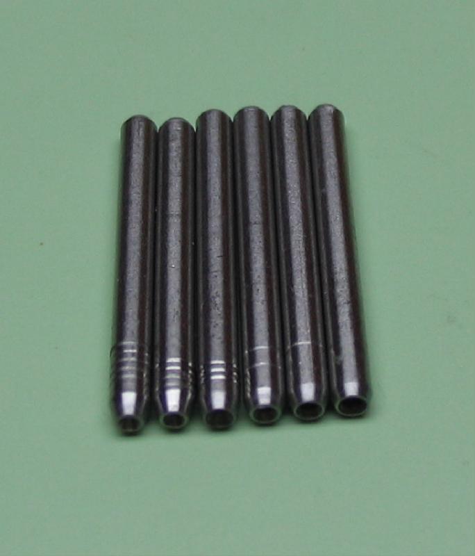
Male centers were made in 1mm, 2mm and 4mm diameter, but all having a 2mm shank and 60 degree point.
 |
 |
 |
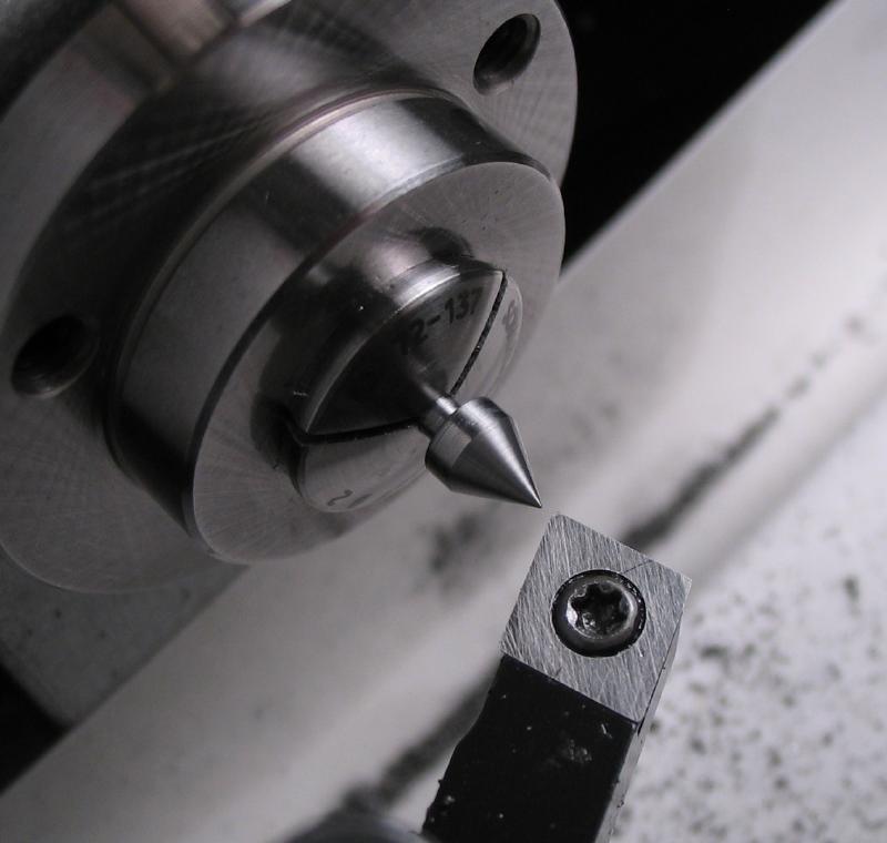 |
Similarly, three plain female centers were made in diameters of 2, 3 and 4mm using the drill point endmill to form the cone.
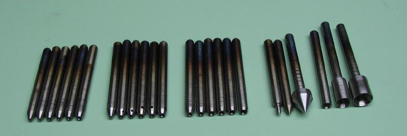
Photos of the completed set of centers after machining. They need to be hardened and tempered.
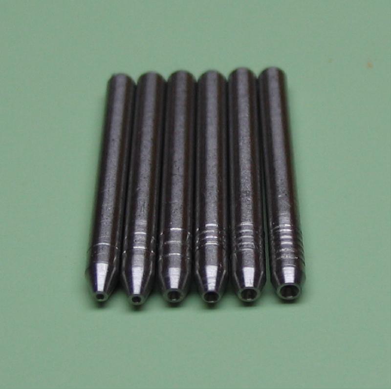
Female centers
|
Female safety
centers
|
Female centers -
'center-drill' sizes
00000 to 1
|
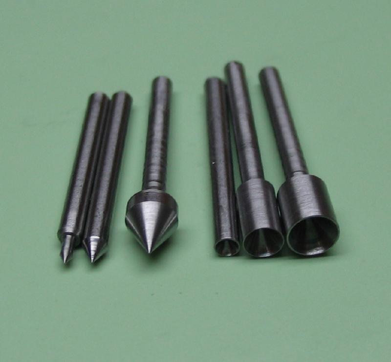
Male centers and plain female centers
|
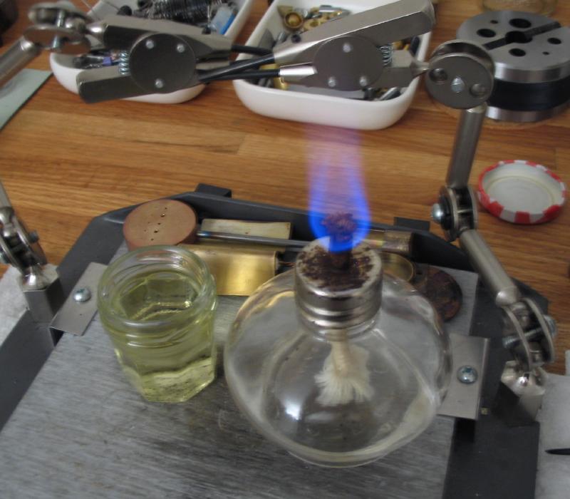
A sheath was made from iron wire for hardening the centers. After polishing, they were tempered using a small cutoff of brass rod which was drilled and reamed about 7mm deep to hold and expose the centers. The brass holder provides more control while heating in the alcohol lamp flame. The color change can be observed moving up the length of the steel. The rear end can have a softer temper, but the heating was stopped by quenching when the tip reached a light yellow color.
|

|

|
The critical surface on the female centers is the 60 degree countersink. This surface was polished with a mild steel 60 degree center with green jewelers 'rouge' mixed with oil, followed by a brass center with diamantine mixed with oil. The polishers were made from oversized rod. A 1 inch length was turned to 1/8" and parted off. This was held in a 1/8" collet and turned to a 60 degree point with the compound rest.
The male centers were polished with hard Arkansas slip stones.
|
|
|
|
|
The completed set of centers.

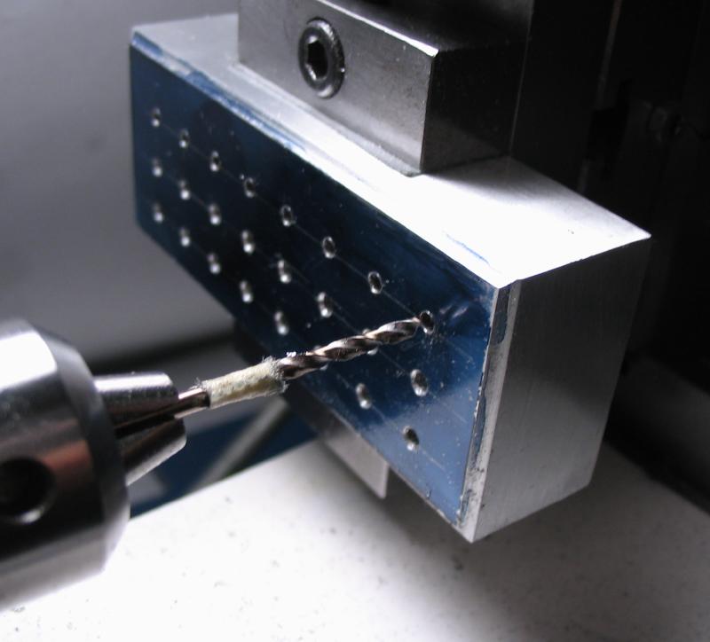
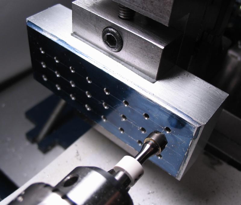
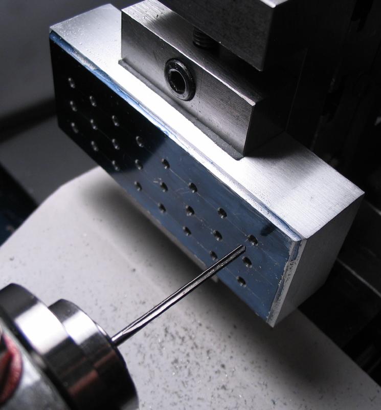
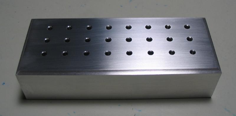
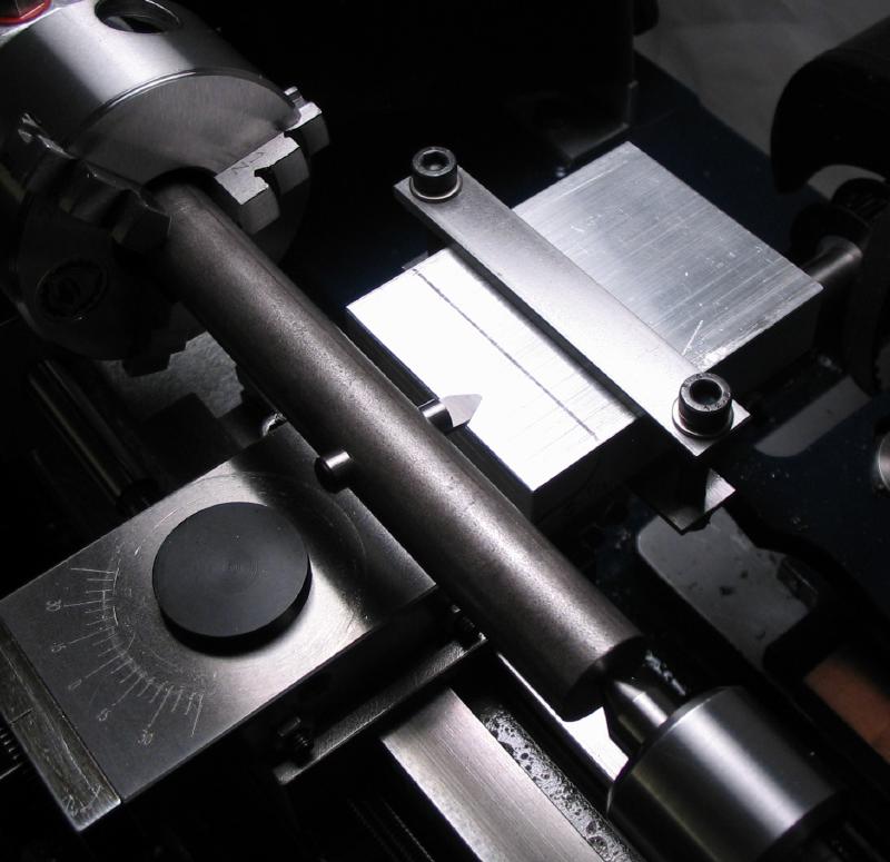
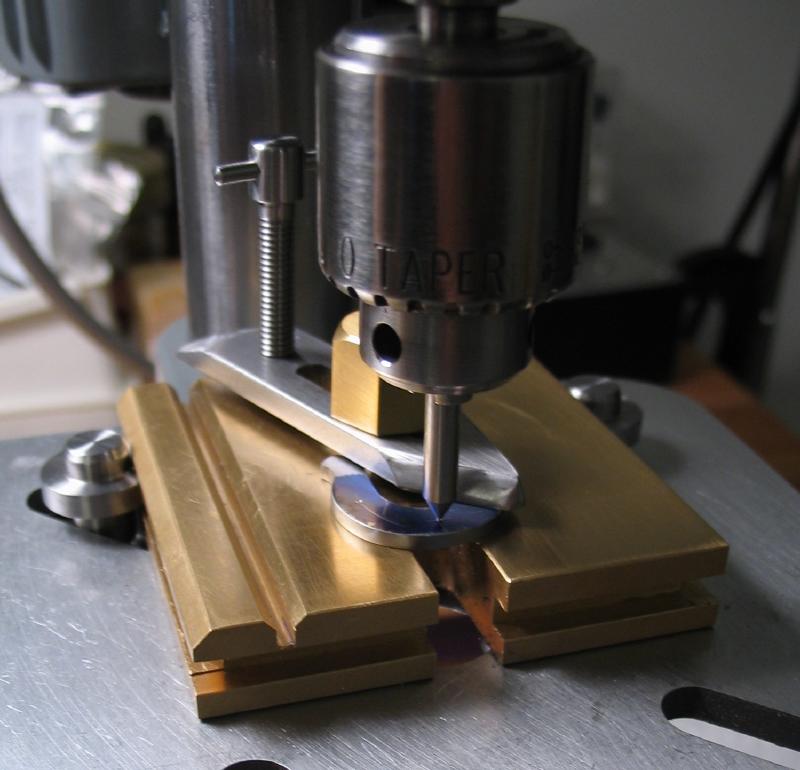
A base was made to accommodate the centers. A 3" length of 5/8" x 1.25" aluminum bar was squared up by milling on all sides with a 1/4" endmill. The top edge was relieved with a 1/8" ball end mill, and the bar was then lightly polished on 400 grit emery paper.
|
|
|
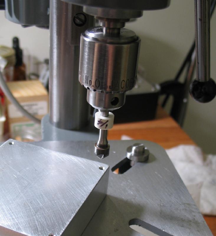
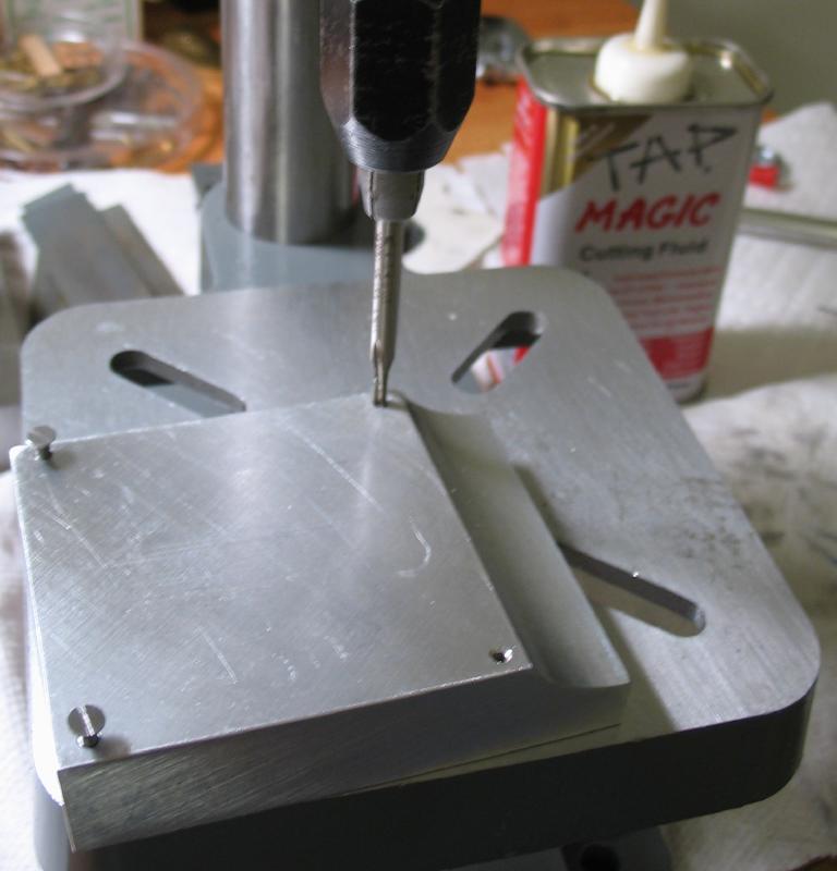
24 positions were laid out and drilled 1.9mm. The holes were then countersunk and reamed 2.0mm.
|
|
|
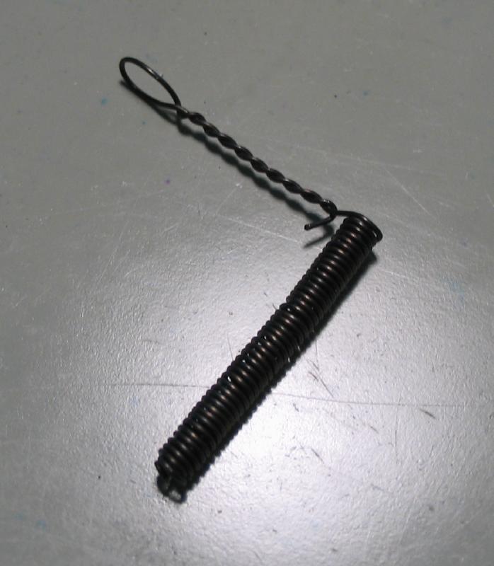
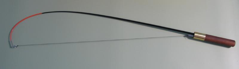
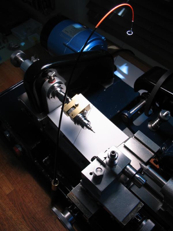
Bow
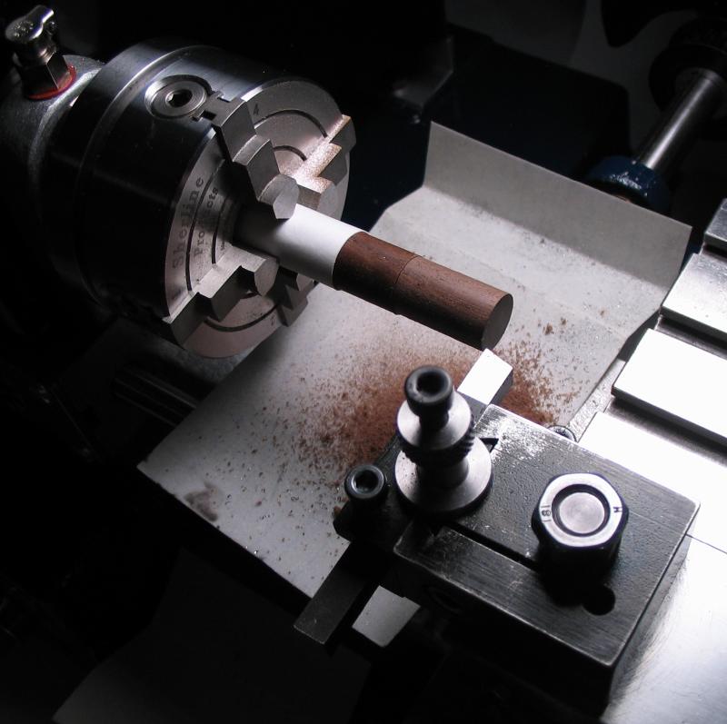
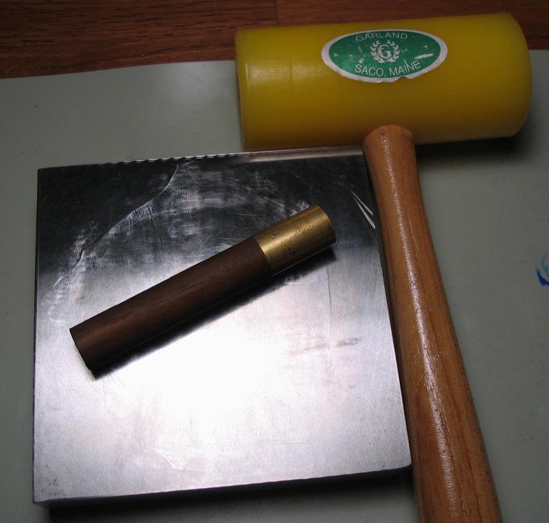
The headstock pulley can be driven with a hand-held bow. The work is started with the handle. A length of 1/2" walnut dowel rod was mounted in the 4-jaw chuck and centered. A 20mm length is turned down to 12.1mm to friction fit a length of brass tubing. The tubing can be tapped on with a mallet, and the work returned to the lathe to trim the brass down to size.
|
|
|
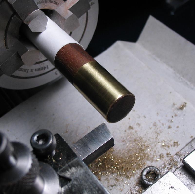
The work is offset in the chuck and drilled 5/32" and set over and drilled 1/8".

|
|
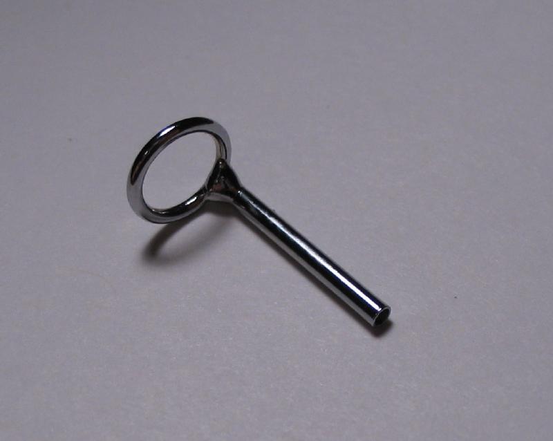
A one inch piece of 1/8" square O-1 tool steel was filed to shape and drilled 0.5mm, the holes were countersunk. This is then tapped into the 1/8" hole in the handle.
|
|
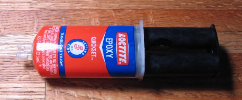
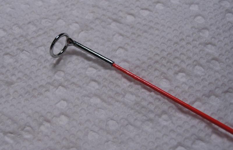
The main portion of the bow is made from a 17 inch, graphite-fiberglass composite, Microlite brand ice-fishing rod blank. The rod blank was under $3, and has a 0.150" diameter end, tapering to 1/32" at the tip. The butt was epoxied into the 5/32" hole in the handle, and the end piece epoxied onto the end of the rod.
|
|
|
The epoxy was let to cure overnight and the bow strung with nylon upholstery thread (Coates S964). Choice of string was purely experimental. The bow is made tight, but loose enough to make a loop for the headstock pulley.
|
|
T-Rest
A replacement T-rest is made to fit the Cowells T-rest mounting fixture. It is narrower than the T-rest supplied by Cowells. Starting with a 40mm length of 16mm diameter O-1 drill rod, it was faced and center drilled with a #2 center drill.
With tailstock center support, the rod was turned down to 5/16" (7.94mm) for a length of 22mm.

The rest is moved to the vertical slide, and the forward face milled flat to a depth of ~2.3mm with a 1/4" 4-flute end mill.
The top surface needs to be milled to approximately 55 degrees. The end of the post was butted against the center slot of the vise and the newly milled face was supported with a piece of 1/16" brass shim to provide a very close approximation. This was checked with a protractor.
 |
 |
The side faces can be milled to meet the milled front face. Perhaps more elaborate means of indexing could be used, such as the dividing head or a square arbor drilled to fit the post. However, the work is easily setup with a machinist square and to sufficient accuracy for its purpose.
 |
 |
 |
The resulting T-rest after machining.
 |
 |
 |
The tool marks are removed with a No.2 hand file followed by a No.6 to smooth.
 |
 |
It was then hardened in oil.

The rest was polished on 400 and 600 grit emery on a glass plate for the flat faces. Shown on the right is the finished rest next to an older and newer versions of the T-rests supplied by Cowells to show the relative difference in size.
 |
 |
Tailstock Components
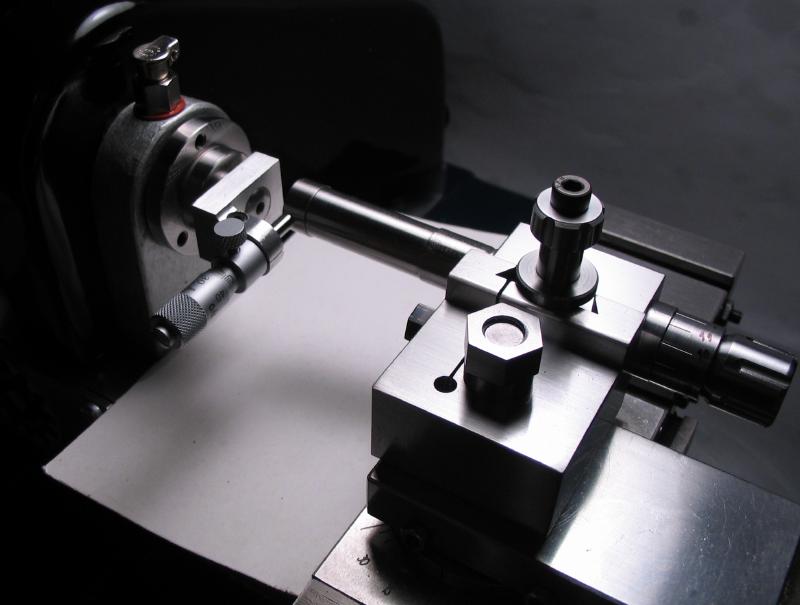
There are seemingly endless number of different accessories that can be made for the tailstock. The principal needs are offset female centers for small diameter turning, a lantern type runner for turning the ends of pivots, and a burnishing bed runner.
The Burnishing Bed Runner
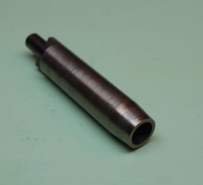
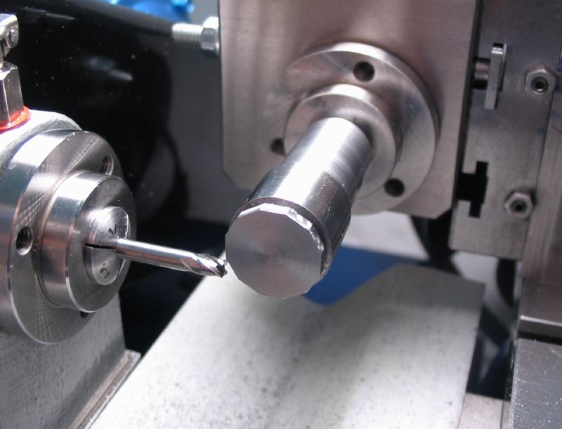
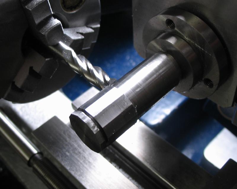
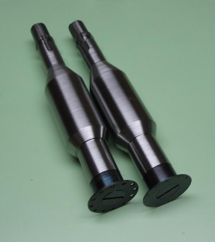
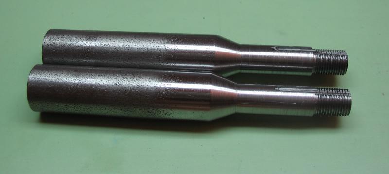
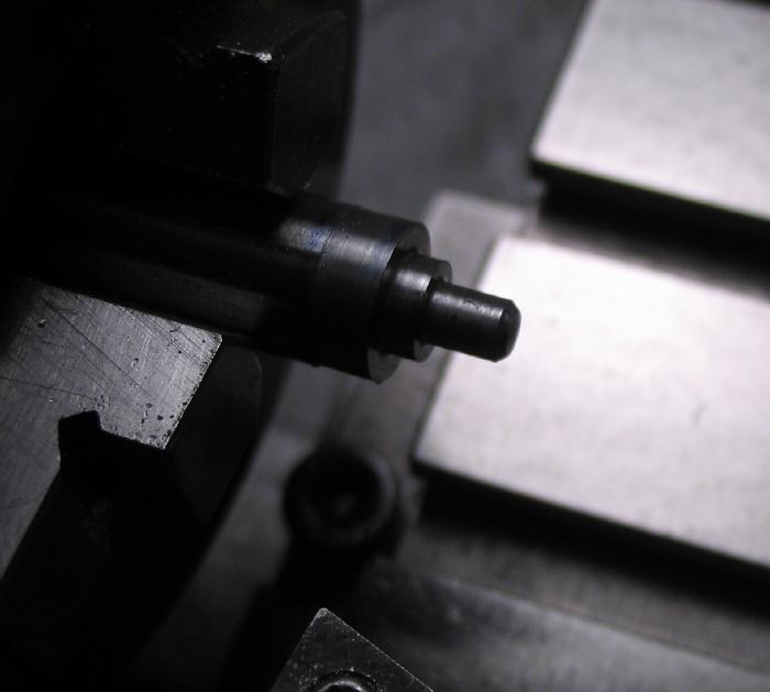
This piece is made to fit the tailstock quill. It will need to be hardened, therefore it is made from oil hardening drill rod (O-1). A 70mm length of 16mm diameter rod was given a B-8 type collet shank. A process that I am becoming very familiar with. Machining tool steel requires a bit more patience than mild steel.
 |
 |
Once the collet shank is made, it was fit to the tailstock and marked for the location of the register pin in the tailstock quill. The register pin will prevent the runner from rotating, that is, of course, why it is there. A groove is made with the parting tool to allow free rotation in the tailstock quill. It can be sufficiently locked into position for use by tightening the drawbar.
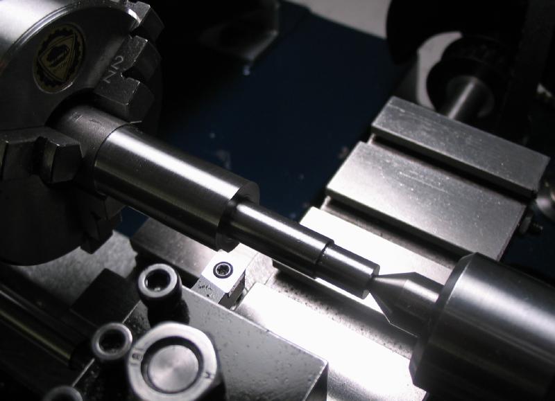
While chucked, 1mm clearance can be turned on the working end of the runner.
The runner is then secured in the headstock by drawbar. The end is turned down to 15mm for a length of 2mm. A groove is made 1mm wide and 1.75mm deep next the turned portion.
 |
 |
The runner is transferred to the dividing head and flats milled onto the reduced diameter to form a dodecagon (12 sides). This requires milling to a depth of ~0.26mm. With the dividing head, 3 and 1/3 turns with a 40:1 worm-screw provides an index of 12.
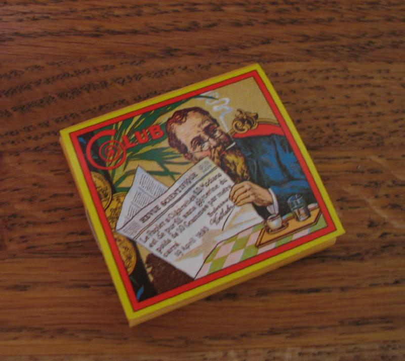
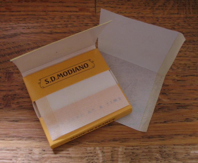
Many machinists describe the use a piece of cigarette paper to zero-set endmills against work. Basically the paper is held between the work and the endmill. With very slow advance it is found where the paper is just barely able to still pull away. Cigarette paper is almost always 0.001" (0.0254mm). It can be checked with the micrometer and added to the lead screw dial. I happen to be using S.D. Modiano - Club (France).
 |
 |
The guiding surface for the burnisher is milled next. These surfaces are one-half the pivot diameter above the bed flange. A 1/4" endmill was used and the cross slide was used to feed the work. The cutter is reset to zero to the flange surfaces for each step to avoid accumulation of any error.
For this prototype piece, I decided to go with the following twelve pivot diameters.
|
1) 0.10 2) 0.14 3) 0.16 4) 0.18 5) 0.20 6) 0.24 7) 0.30 8) 0.40 9) 0.50 10) 1.00 11) 1.20 12) 1.40 |
 |
The pivot beds are milled using a 90 degree double angle cutter and to depths equal to 0.65 times the desired pivot diameter. To zero the cutter, the flange surface was colored with blue ink, the cutter then fed until it just begins to show a mark. The dial is then set to zero.
The surfaces were lightly stoned with hard Arkansas slip stones to remove burrs. This was kept to a minimum so as to not affect the depths that were so carefully machined.
 |
 |
The runner was returned to the dividing head to mill flats on the reduced diameter portion. These flats are to be stamped with the corresponding pivot diameters.

Using 1/16" number stamps, the corresponding sizes were stamped onto the runner. The flats were milled with a ¼" endmill, the runner was supported on a ¼" lathe tool blank which was placed on a hardened steel bench block. The stamps were held free-hand and struck with the flat side of a 4 ounce ball pein hammer. A piece of Rodico was used to support the free end and keep steady. Overall, a fairly makeshift setup, but it served its purpose.
 |
 |
The runner was coated in boric acid prior to heating to red heat to minimize the amount of blackening oxidation. Those who have browsed this site may have noted the use of this method in other endeavors. It does help prevent blackening, however, it always results in a glass-hard crust which is just as time-consuming to remove, so I go through phases of use and disuse.
The entire runner is hardened in oil and left fully hard for use. The surfaces were again minimally touched up with an Arkansas slip stone only to remove oxidation.
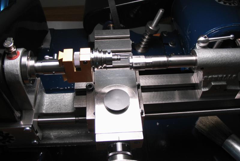
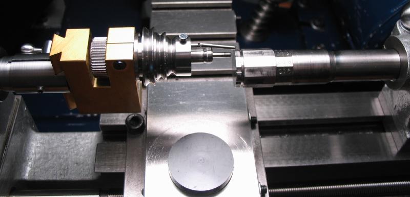
The runner setup on the lathe with the headstock (in its current state of completion).
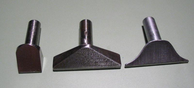
Lantern Runner
The lantern runner and point center runner will use reusable arbors that fit the collet holding tailstock quill. The working portions will be made from tool steel and hardened and tempered to a pale blue (to be softer than the work). They will attach with a screw, and therefore easier to replace without having to make a new collet shank. The arbors do not need heat treatment and can be made from mild steel, making things a bit easier.
I made the lantern runner arbors from 5/8" diameter 12L14 mild steel. The usual method of making the B-8 collet portion was repeated. The largest diameter will be 15mm.
 Turn major diameters |
 Thread for drawbar - B8 |
 Center work relative to headstock |
 Mill keyway for spindle register pin |
The working end is center drilled and with rotating center support it was reduced to 10mm for 16mm.
 |
 |
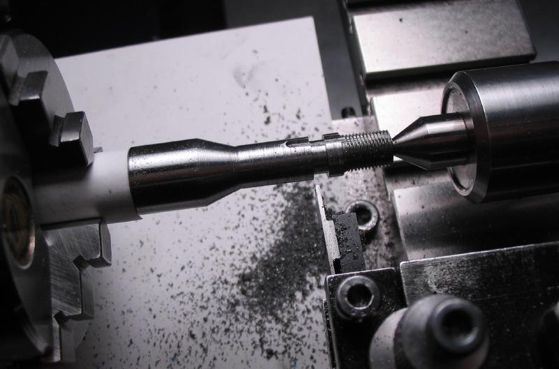
The mounting surface is 6mm diameter to fit the insert and was turned for a length of 4mm. The remaining plain portion was turned with the compound slide to 30 degrees. It is drilled and tapped M3x0.5 for the retaining screw.
 |
 |
 Drill 2.5mm for M3x0.5 tap |
 Countersink to assist tap and mate with screw |
 |
 Finished Arbor for the lantern runner (screws made below). |
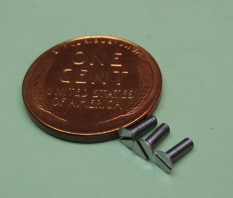
A batch of screws were needed to retain the inserts on the arbors. They are turned from 8mm O-1 drill rod. This was a cut-off of drill rod that was bent from shipping, and I designed the screwheads to be 7.5mm, so that the rod could be turned down to a clean and true diameter. The 7.5mm diameter was turned, and a 3mm diameter for a length of 8mm. The end is chamfered to assist in starting the threads.
The work was threaded with the tailstock die holder.
The screw was then parted with the Warner 1/64" parting tool.
 |
 |
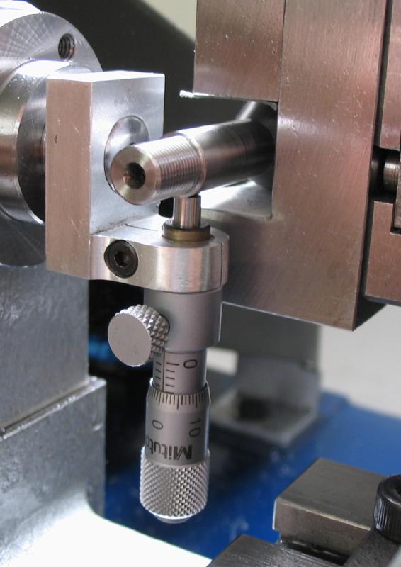
The screwheads were slotted using a 0.032" (~0.8mm) slitting saw mounted in the headstock and the screw held in the dividing head on the vertical slide. The centering micrometer was used to center the slitting saw.
 |
 |
The screws were polished on emery paper and hardened and tempered to a blue color.
 |
 Hardened in oil and repolished |
 Tempered blue |
The lantern inserts are made from 16mm O-1 drill rod. The ends are turned to provide clearance for the graver in use. The rod was pilot drilled to assist in parting off. A boring bar was used to give a 30 degree chamfer to mate with the rotating center
.
 |
 |
 |
 |

The parted work is then faced and bored to fit the arbor and retaining screw. To hold the insert blanks, a piece of 5/8 brass from the scrap bin was cleaned up, faced and bored. The ring was sawed to provide clamping movement. It was returned to the 3-jaw chuck and position noted, however, it should not be removed until work is finished. It was bored to fit the 10mm portion of the insert blanks.
The insert is faced to final thickness, measuring before mounting and checking with feeler gauges. One is 0.3mm thick for small pivots and a second was left 0.5mm for larger pivots.
The insert is then through bored to fit the arbor (6.0mm), then counter bored to fit the screwhead (7.5mm x 2mm deep).
 |
 |
The completed insert blank.
 |
 |
 |
 |
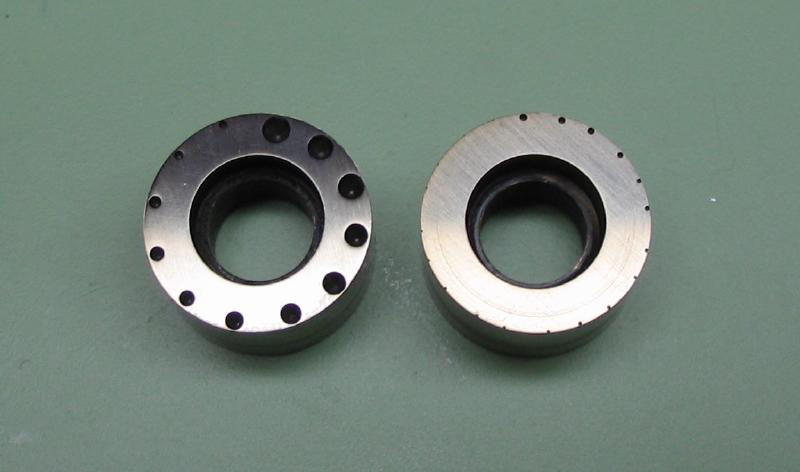
The mounted insert and arbor is secured in the headstock. A groove is turned in the face which will become the pitch circle for the various diameter pivot holes. The arbor is moved to the collet-holding toolpost, and the holes made by drilling through with appropriate sized drills and then countersinking 60 degrees with a drill-point end mill. The finished part was stoned with India and Arkansas stones to remove burrs and turning marks. The inserts are lightly broached to remove burs, hardened in oil, and tempered to a light blue.

|
|
|
|
|
 |
|
With the machining complete, the arbors can be grooved to pass the register pin.

|
|
Point-Center Runner
The arbors for the point-center runners were made from 1/2" diameter 1018 mild steel rod. After exhausting my supply of 5/8" 12L14 steel, I found a length of 1018 steel rod in the drawer. The same basics dimension are given to these arbors as well, B8 shank, reduced to 12mm and a 6mm spigot to hold the inserts, and tapped for a retaining screw.
 |
 |
 |
While making a tailstock center from ½" drill rod, the insert blanks were made. The rod had been given a B8 shank but was left long enough to make the inserts and leave enough to complete the project. The work was mounted in the headstock and drilled 1/8" and bored to 6mm to match the arbor.
 |
 |
 |
 |
The end was counterbored to accept the screwhead.
The blank can then be parted off..
 |
 |
The parted blank was fixed to a freshly faced cement arbor and the parted side faced. The boring was countersunk to provide a good fit to the arbor.
The work is mounted in the collet holding tool post. A 60 degree drill point end mill is used to mill the 'centers' on the perimeter of the insert. The micrometer centering tool is used to position the runner at half the pivot diameter. The insert is milled to a depth that can be calculated, but easier to observe when the drill begins to break the edge of the insert. In use these resulting centers allow turning with a graver on small diameter work.
On the first insert 12 pairs of centers are milled (0.10 to 0.60mm). The second insert is given 12 centers from 0.70 to 2.00mm.
|
|
|

The inserts were then hardened in oil, polished, and tempered to a straw-yellow color.
With the machining complete, the arbors can be grooved to pass the register pin.
|
|
|
|
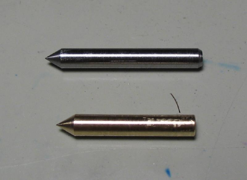
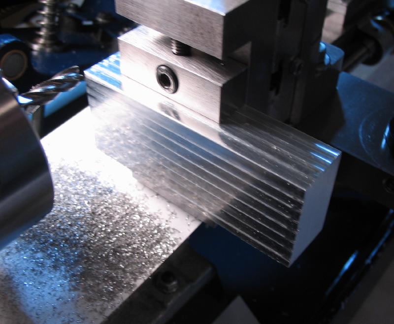
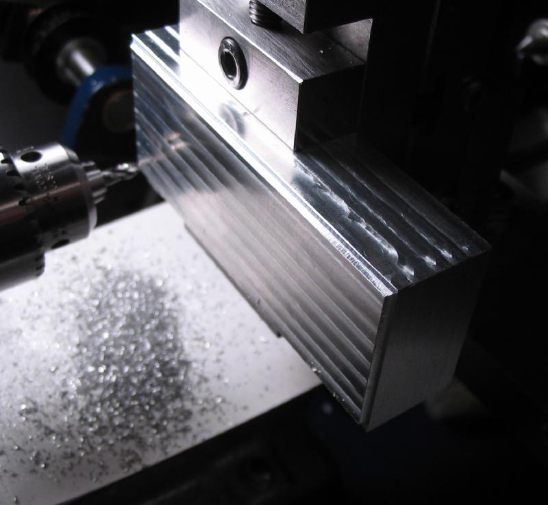
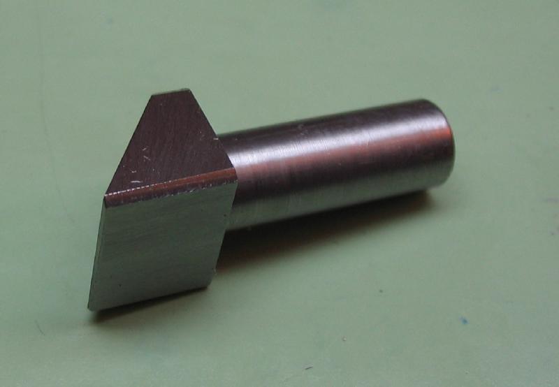
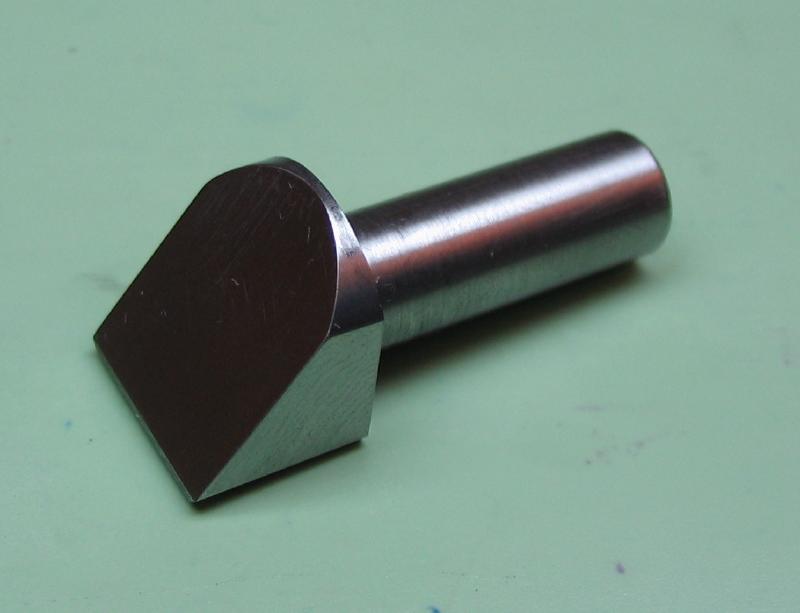
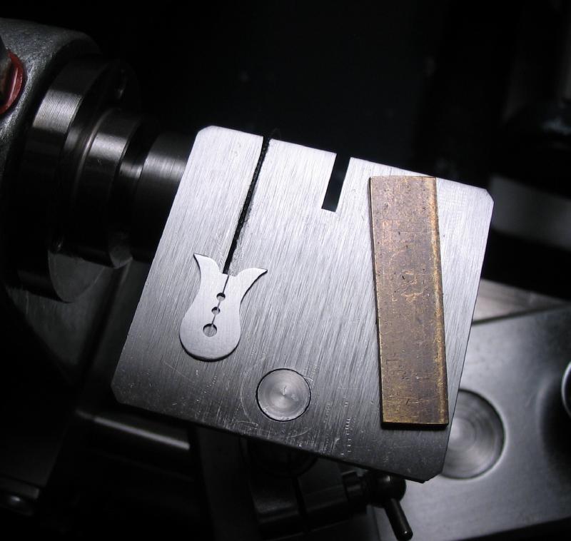
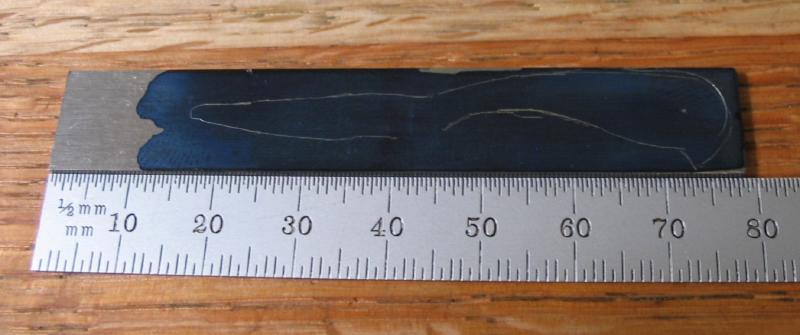
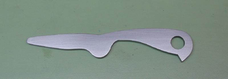
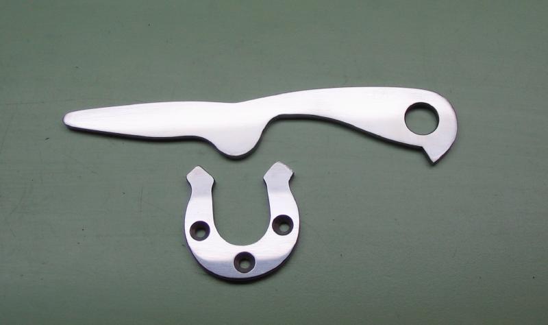
Work Carriers (work-drivers, entraîneurs, mitnehmer, arrastradores, etc.)
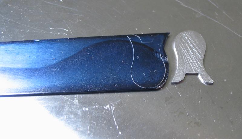
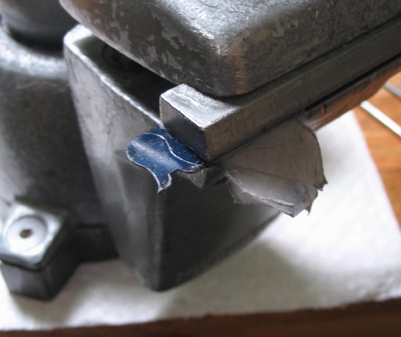
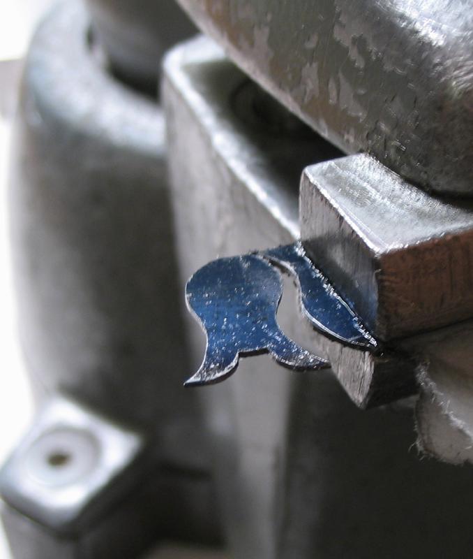
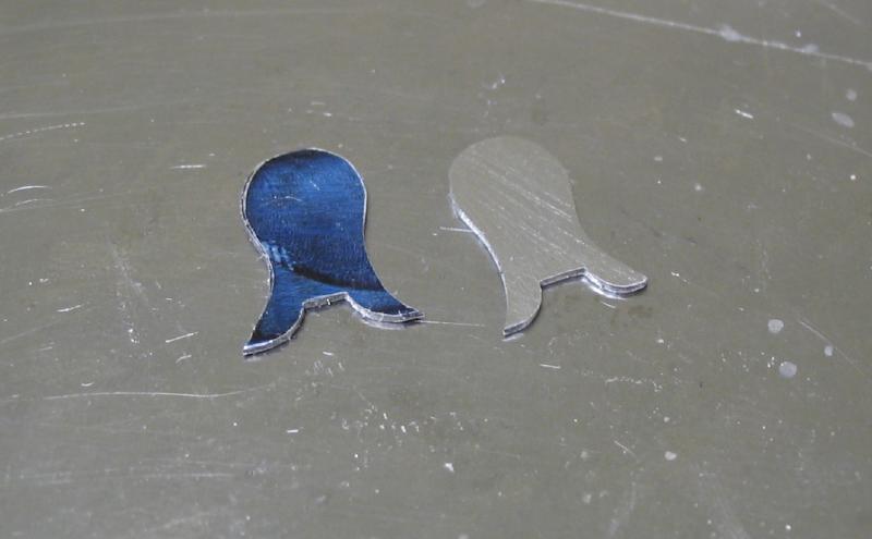
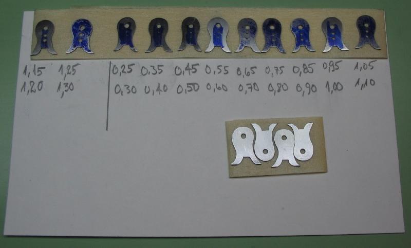
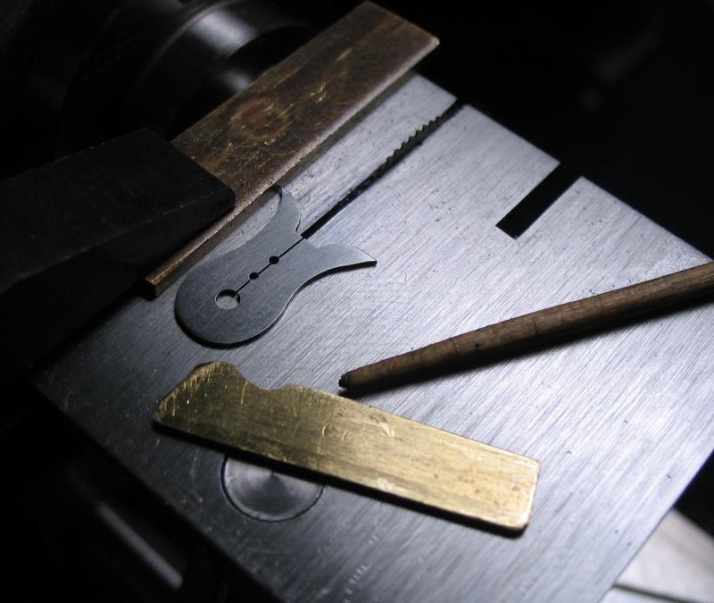
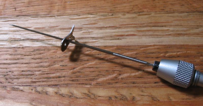
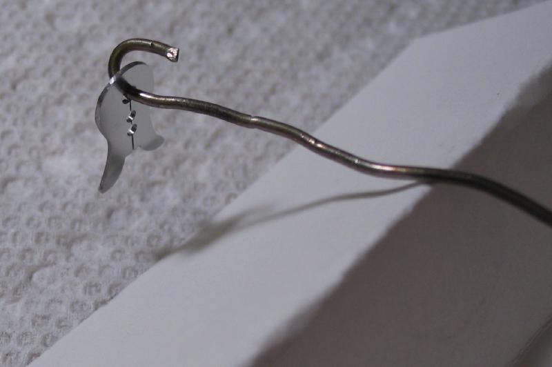
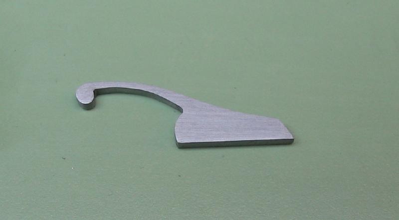
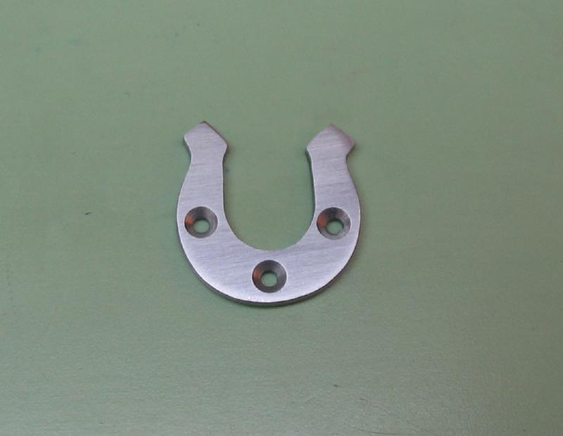
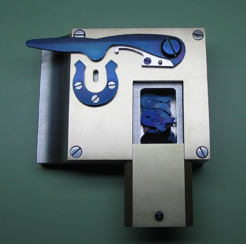
The work held between centers is driven by the pin on the headstock pulley which engages a carrier that is spring fit to the work. These carriers are essentially small spring clamps that are drilled to fit various diameter work. They are usually shaped like a fish, with an 'eye' that fits the drive pin, and tail fins that can also catch the pin as well.
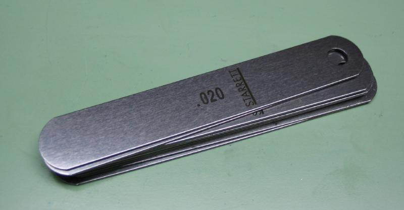
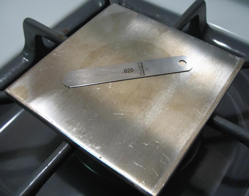
I made them from 0.020" Starrett feeler gauge. The width is 1/2" (12.7mm).
It is old stock, and I was able to purchase a package of them cheaply.
I made them from 0.020" Starrett feeler gauge. The width is 1/2" (12.7mm).
It is old stock, and I was able to purchase a package of them cheaply.
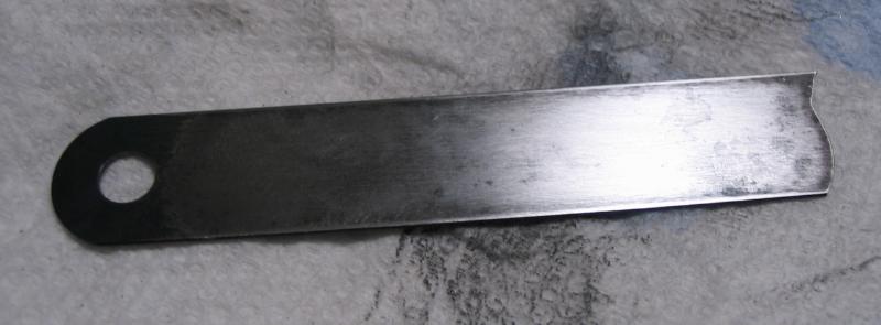
The gauge is spring tempered, and to be able to work the steel, they need to be annealed. I used a square block of 1/4" aluminum plate (6061); its usual function is for making espresso. The gas burner can be used to ensure a slow cool down. The gauge was lifted an raised to red heat with a propane torch and then laid back on the hot plate to cool.
|
|
After some difficulty in sawing the first piece, the gauge was annealed again.
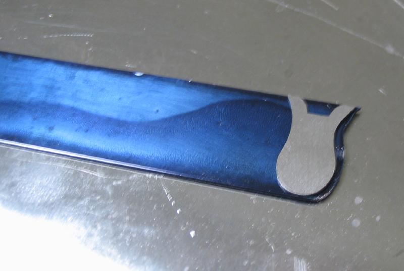
The shape allows for the pattern to be repeated with little waste of metal.
Depending on one's drawing and sawing skills....
|
|

|
|
|
|

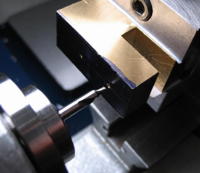
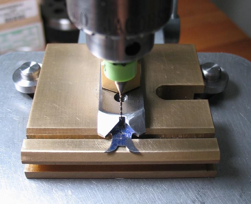
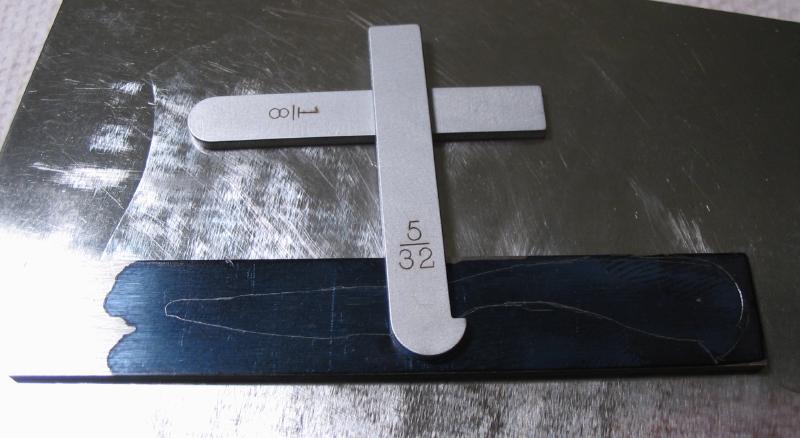
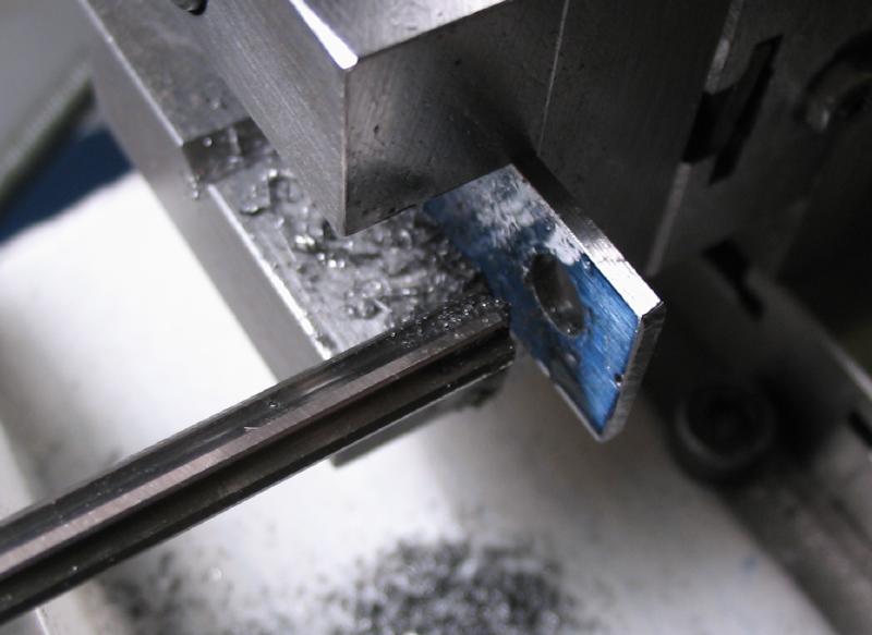
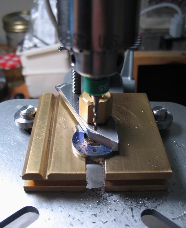
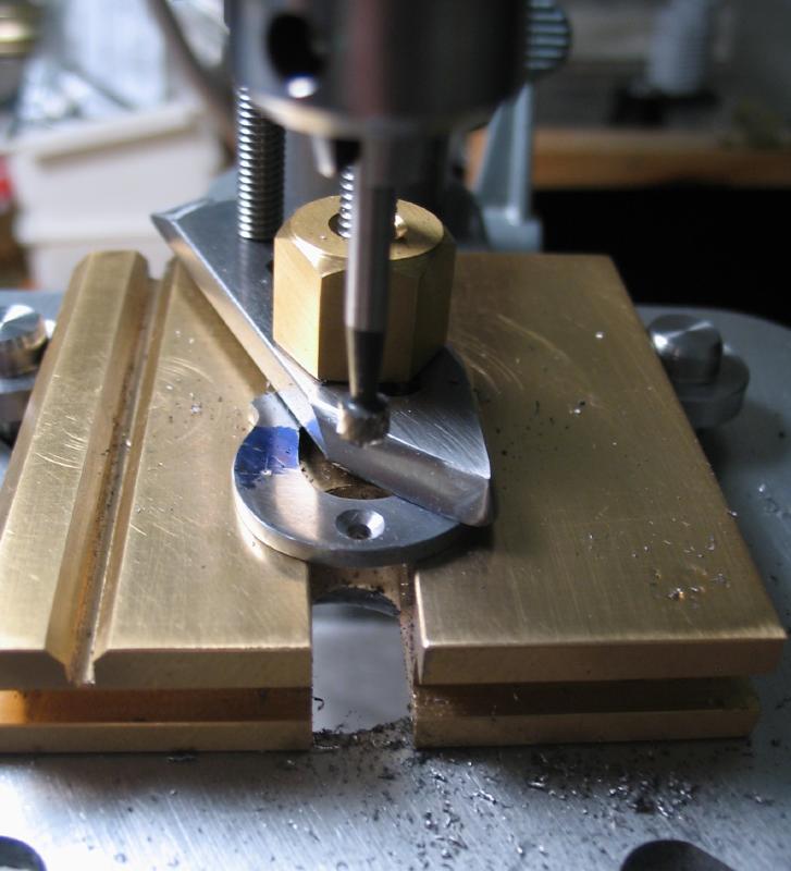
The catch hole was laid out, center punched and drilled 1/16".
The fingerplate can be used to hold the work steady. A 1/8" piece of drill rod was turned with 60 degree points, and one end reduced in diameter. It helps center the drill to the center punch mark. The drill head is raised and a drill bit exchanged into the chuck.
|
|
|
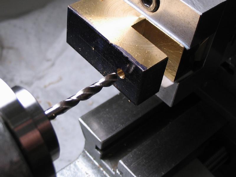
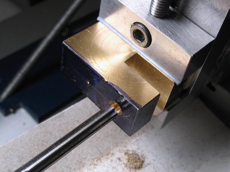
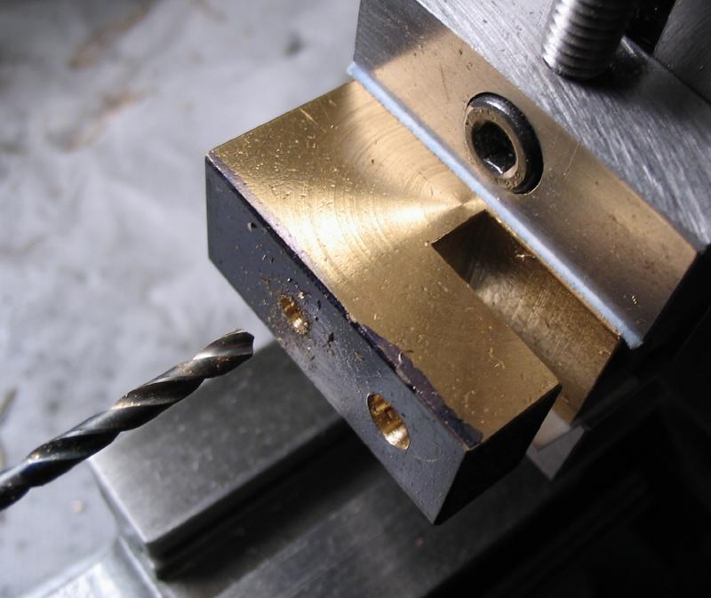
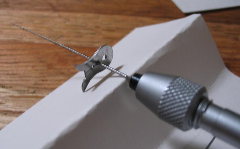
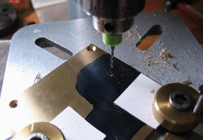
A center line was scribed, and two punches for work holding positions. The holes were drilled in a range from 0.25mm to 1.30mm in 0.5mm steps. Custom/special sizes can be made as needed, of course.

|
|
|
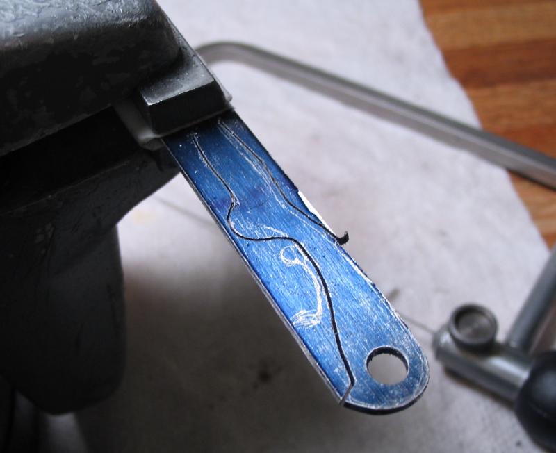
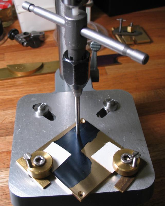
The drivers need a slit cut through the work position holes and into the catch hole. This provides a means of prying open to insert work. The previously made saw table was given a new slit closer to the edge using the Cowells saw table.
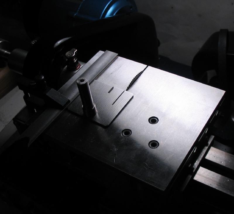
The saw table can then be mounted in the T-rest attachment with a 0.006" slitting saw mounted on its arbor.
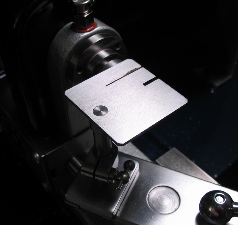
|

|
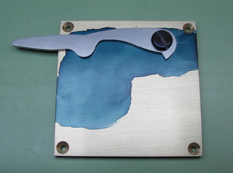
The larger sizes were cut free hand, but it was quickly apparent that more control would be needed. A fence was setup with a small piece of brass and a toolmakers clamp. The drivers were maneuvered with small brass strips and peg wood.
|
|
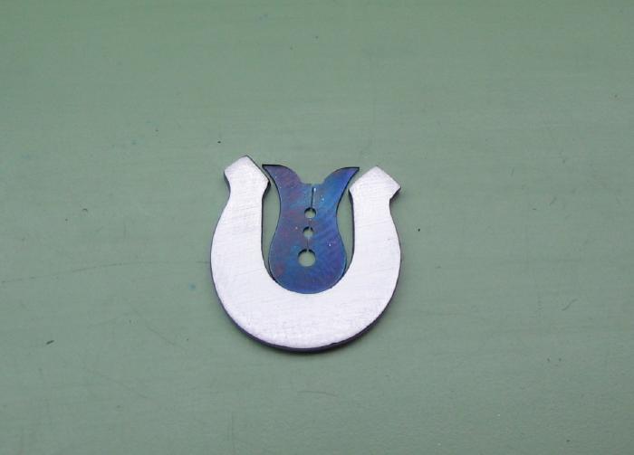
The holes were lightly broached to remove burs and then finished with a smoothing broach with oil. The finished carriers are dangled on a piece of stainless steel wire in the alcohol lamp to bright red and quenched in oil. After re-polishing on emery paper, they are tempered to blue on a strip of brass. This returns them to the spring state.
|
|
|
|

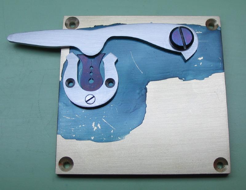
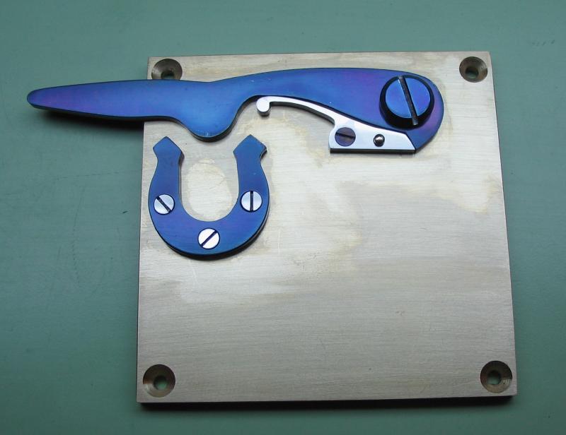
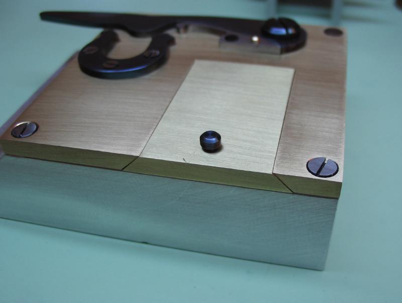
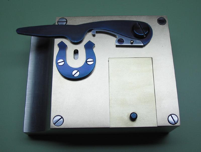
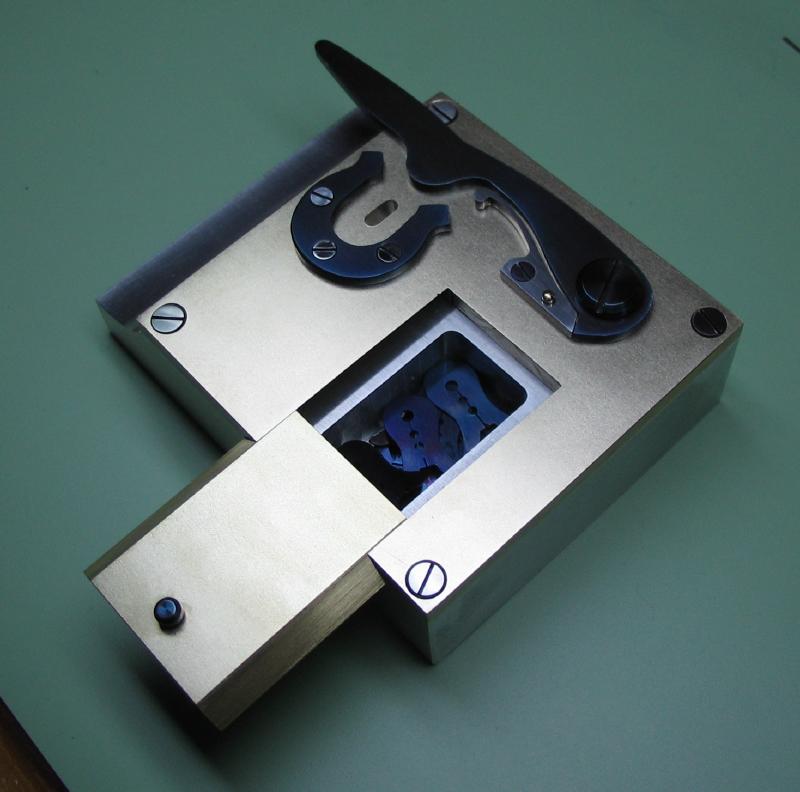
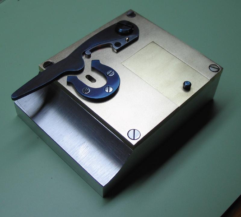
Driver opener and storage box
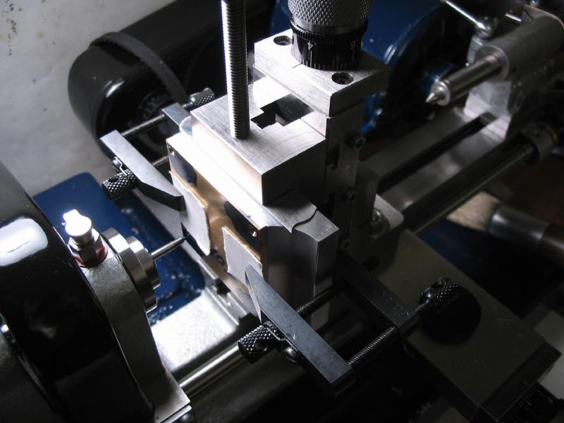
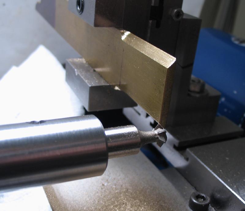
Described below is the storage box with opening mechanism for the work carriers. The work starts with the base piece. A fly-cut edge is to be attempted. So first, an arbor for holding a fly-cutter is made. A 5 inch piece of 5/8 steel rod is sawed off (or held in the vise).
The rod is faced and center drilled on each end using the steady rest for assistance.
|
|
At 3 inches from one end it was center drilled, and drilled 5.80mm. The hole is then reamed 6.00mm for holding a 6mm cutting bit.

|
|
|
|
The rod is turned 90 degrees and drilled 4.2mm for tapping M5x0.8.
An M5 set screw can be used to secure the cutter.
|
|
|
The cutter is started from 6mm O-1 drill rod. The non cutting end is faced and chamfered 45 degrees. The cutting end is taper turned 30 degrees, the tip rounded over with a file and then polished with oil stone and Arkansas slip stones.

|
|
|
The bit was moved to the dividing head and locating flats milled onto opposing sides of the shank. It was reversed and as best as possible, kept in alignment with one of the flats. The cutting tip was milled close to the center line.

|
|
The milled surfaces could then be touched up on slip stones. The cutter was then hardened in oil and tempered to a straw color.
|
|

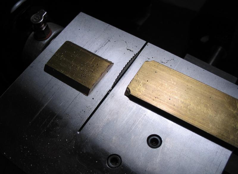
The base is made from a 2.5" length of 2" x 5/8" aluminum bar (6061). This happened to be the first job for the Hand-I-Hack (although already pictured above), the machine makes hacksawing almost effortless.
The cut-off is clamped to the lathe cross slide for fly cutting an edge. A pair of clamps were made from a strip of 1/2" x 1/16" O-1 gauge plate (to fit in the T-slot) and a 1/2" x 1/8" strip of mild steel. They are drilled 5mm while held together and fitted with 1.5" M5 socket head screws.

|
|
|
|
The coverplate is made from a 2" x 2" x 1/8" piece of brass plate (360). The edges were milled to get fairly squared up.
|
|
The coverplate will attach with countersink-head screws. 4mm O-1 drill rod was turned down to 2mm for 8mm, and the 90 degree included angle head turned with the top slide. The work was threaded M2x0.4. It was then parted off.
|
|
|
|
The screwheads are slotted on the lathe, and polished on emery paper. They were used in their annealed state while fitting the brass cover plate, and then hardened, polished, and tempered blue.
|
|
|
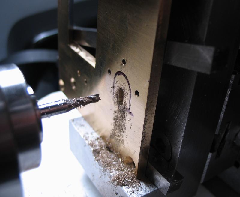
The base and coverplate were aligned as best as possible and fixed with toolmakers clamps. A position for a screw at each corner was laid out (3mm from edges) and centerpunched. The work was mounted in the machine vise. The positions were found using a point, spot drilled, drilled 1.6mm for tapping M2x0.4, drilled 2.0mm through the brass, and then countersunk to match the screwheads.
|
|
|
|
|
|
The parts were separated, the base was lightly countersunk to remove burs and to start the tap. The holes were tapped M2x0.4 using the drill press to help keep aligned.
|
|

|
After securing with screws, some of the edges can be milled to even things up.
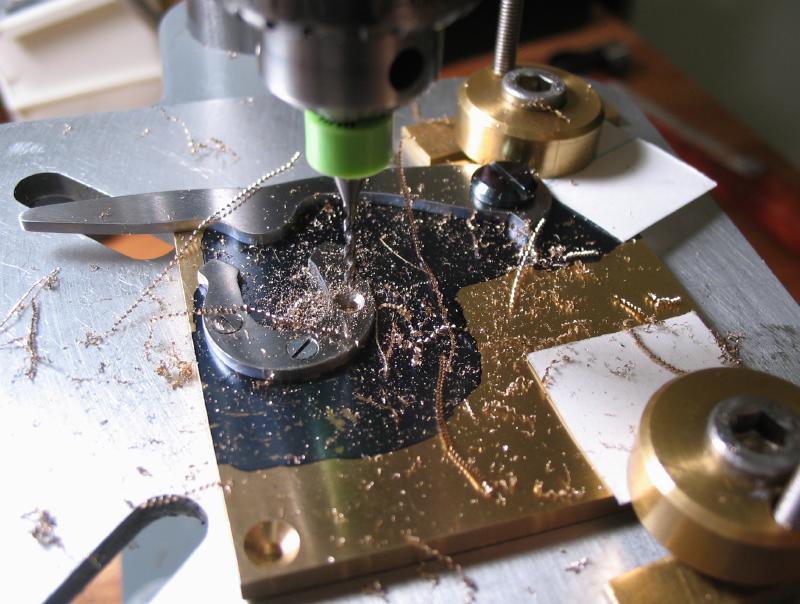
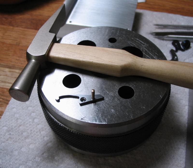
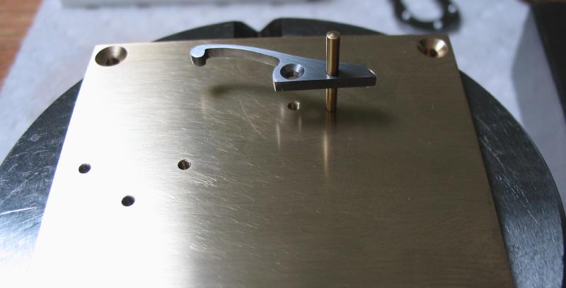
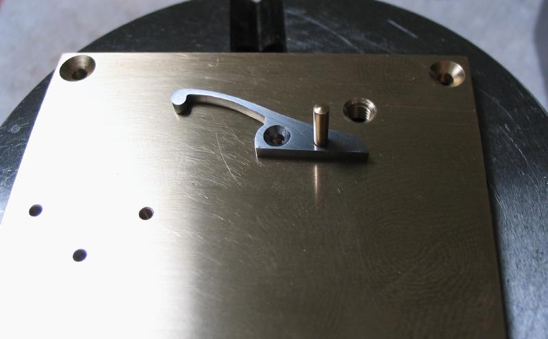
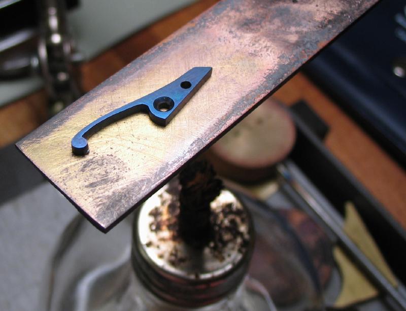
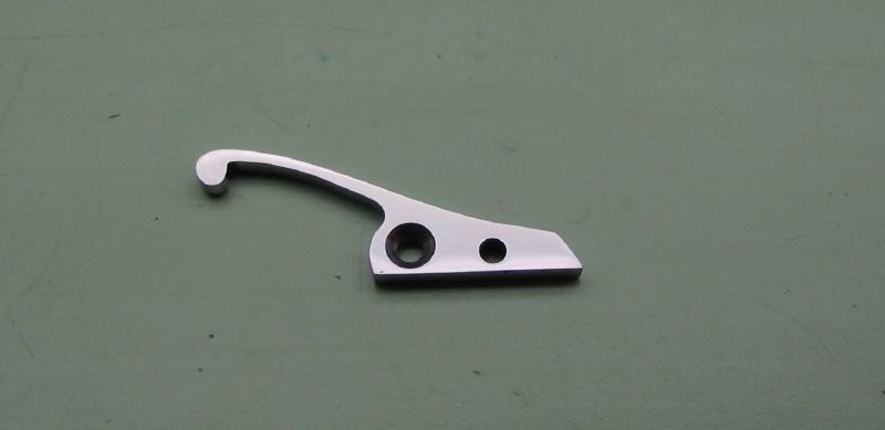
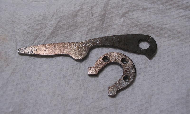
The opening lever is made from 1/16" O-1 gauge plate. A 1/2" wide strip was punched for the screw position and the basic outline of the lever scribed onto the surface. The shape of the portion that contacts the work drivers was determined with radius gauges until a good fit was found. The radius can then be scribed onto the plate.
|

|
|
The plate was mounted in the machine vise and drilled 4.90mm and then reamed 5.0mm.

|
|
The shape is cut out with the piercing saw and filed to clean the edges. A spring was scribed out and with careful sawing it can share the cut.
|
|
|
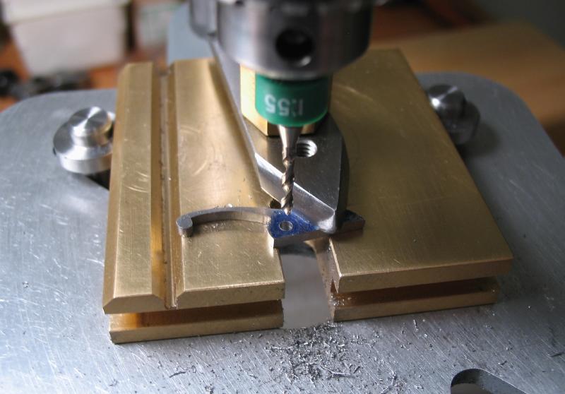
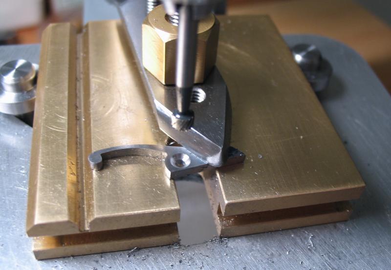
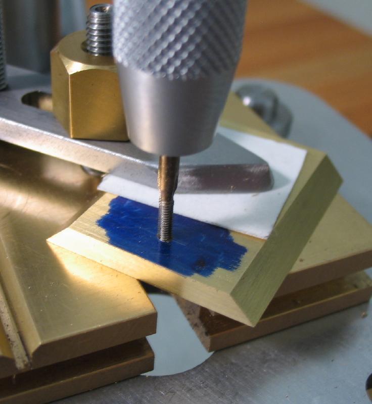
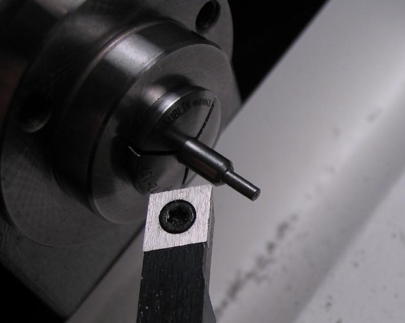
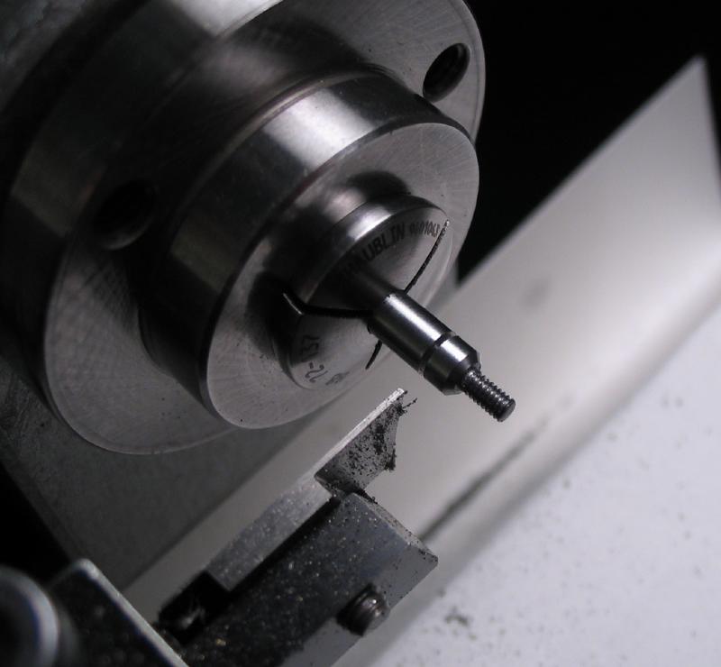
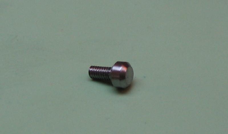
The opening lever is secured with a shoulder screw. It was made from 8mm O-1 drill rod, and turned to provide a 5mm pivot for the lever and to be threaded M3x0.5. The screwhead was given a generous 45 degree chamfer.
|
|
|
The screwhead was sawed 0.032". Hardened in oil and tempered blue.
|
|
|
|
The position for the screw was scribed onto the coverplate. The position centerpunched and the plate was fixed to the drill press table. The position was drilled 2.5mm and tapped M3x0.5. The lever can be mounted to the plate.
|
|
|
|
The work drivers will be supported against a small cut-out of 1/16" O-1 gauge plate. A horse-shoe shape was drawn using a driver as a template of the dimensions needed. The shape was sawed out with a piercing saw and cleaned up with files.

|
|
The support piece will be secured with three countersink-head screws. They were made from 3mm drill rod and given 1.5mm threads. They are smaller versions of the screws made above. The screwheads were slotted 0.016". They are polished, hardened in oil, repolished, blued, and the heads given a final polish.
|
|
|
The support piece is drilled for the screw positions. They are laid out, and center punched. The positions found on the drill press, drilled 1.55mm, and then countersunk with a 90 degree setting bur.
|
|
|
The position for support piece was found on the coverplate, and the lower screw position drilled and tapped 1.5mm. The screw is inserted and the other two positions can be ascertained and drilled and tapped.
|

|
|
|
The spring is drilled 1.5mm to clear the screw, and countersunk 90 degrees for the screwhead. The position for a steady pin was determined and drilled 1.25mm.
|
|
|
The spring position was tested and the screw hole drilled and tapped. With the spring screwed into place, the position for the steady pin was drilled through 1.25mm.
|
|
The spring was broached open to fit a brass taper pin. The pin was hammered into place, and the coverplate then broached to fit as well.
|
|
|
|
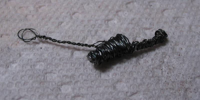
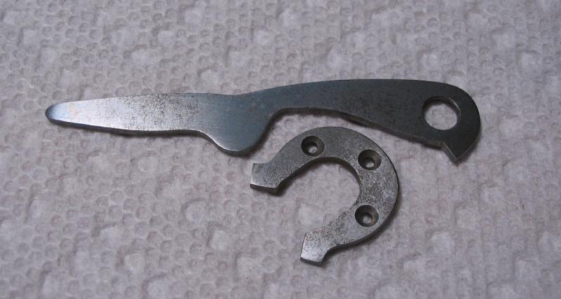
The spring can now be hardened and tempered. It was wrapped in fine iron wire for hardening, and after repolishing, it was tempered blue on a brass plate. The spring was then repolished.
|
|
|
The lever and support piece were coated in boric acid and hardened in oil. The crust left from the boric acid is shown in the photo. This crust was removed by rinsing under hot water. It is difficult to remove by physical means. The surface has what looks like a light rust, but is easily polished up.
|
|
|
Both pieces are then tempered blue.
The cover to the storage compartment was made from 1" x 1/8" brass plate. It was mounted in the machine vise and dovetails milled using a 90 degree double angle cutter. Several passes were required due to the small size of the cutter. A length of about 32mm was then sawed off using the table saw attachment.
|
|
|
|
The dimensions of the shorter width of the lid were scribed onto the plate. The table saw used to make the first two cuts. The section is then removed with the piercing saw.
|
|
The plate was setup in the vise and given matching dovetail cuts. Where the cutter cannot reach, it must be formed with a file. It will be preferable that the final fit be snug. So the final finishing is by filing and emery paper, but the milling step gives a good starting point. With some ink on a glass plate, the surfaces of the dovetails were rubbed to show high spots, this helped to keep a even surface.
|
|
|

The cover was drilled 1.25mm and tapped 1.5mm.
|
|
A small knob was made from 3mm drill rod. It was turned and threaded 1.5mm. The head was chamfered 45 degrees on either side. After polishing it was hardened in oil and tempered blue.
|
|
|
|

|
The base is then setup in the machine vise and a pocket milled out. The dimensions were to fit the space, 13mm wide, 25mm long, and 10mm deep. The milling was done with a 3mm 4-flute carbide endmill.

|
|
A recess for inserting work into a driver while open was milled through the coverplate. A 4mm long slot was cut with a 2mm endmill.
The coverplate was brushed with a steel wire wheel to give a frosted finish, and the components reassembled.

|
|
|
|
