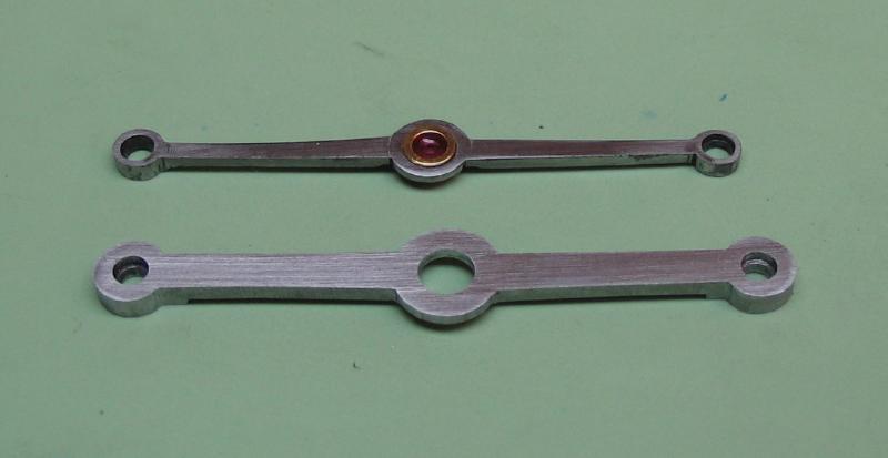
I made the bridge and pillars twice, the first attempt is presented first. Scroll down to "Remaking the bridge" further down on this page to see the second and current version.
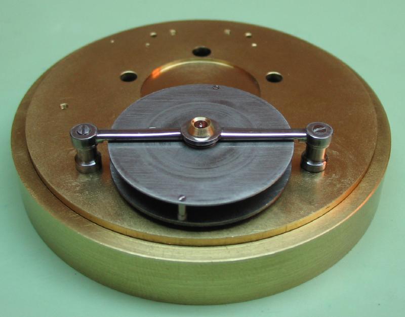
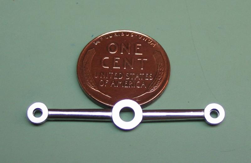
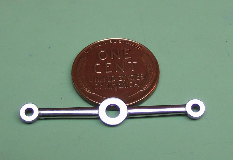
The Carriage Bridge Pillars
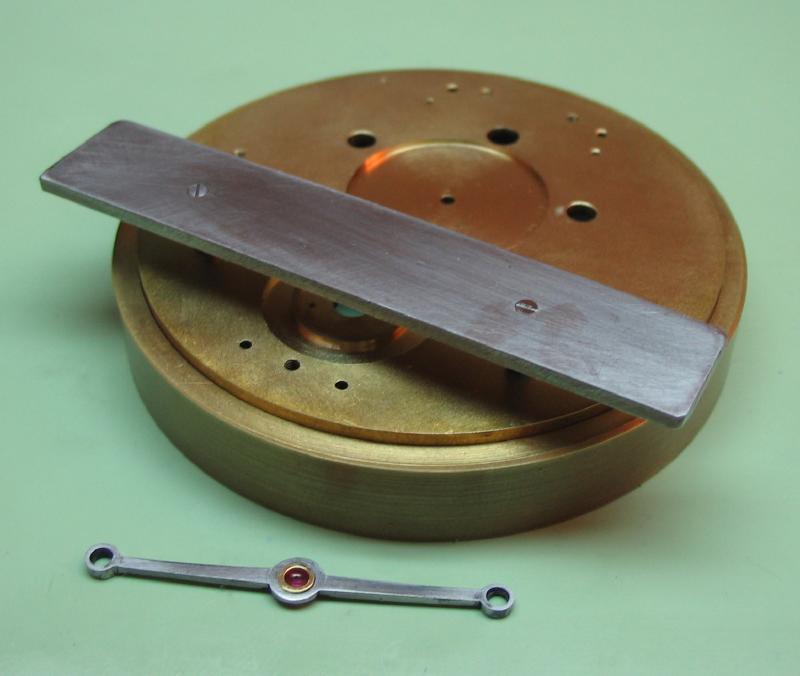
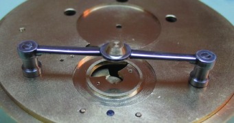
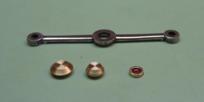
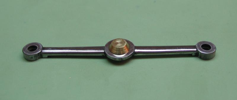
The tourbillon carriage is mounted beneath a steel bridge. This is started with the bridge pillars. Of which two will need to be made.
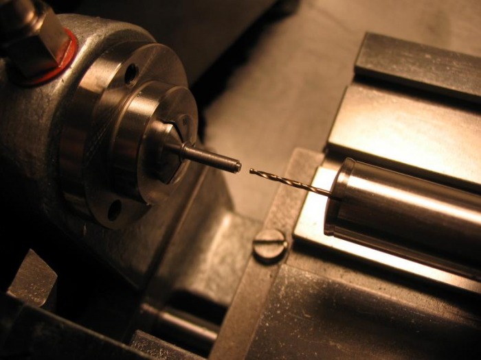
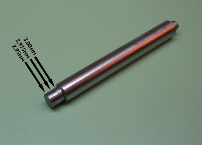
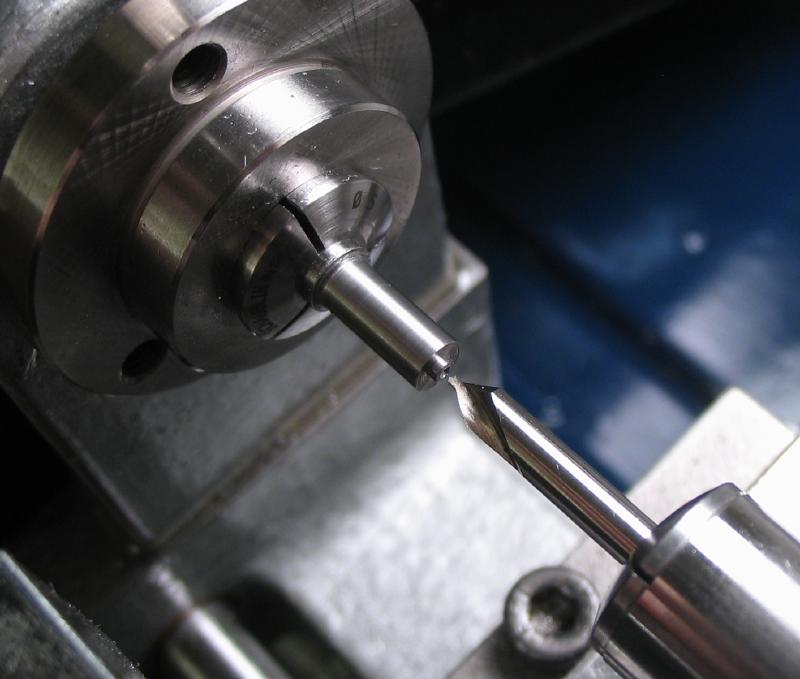
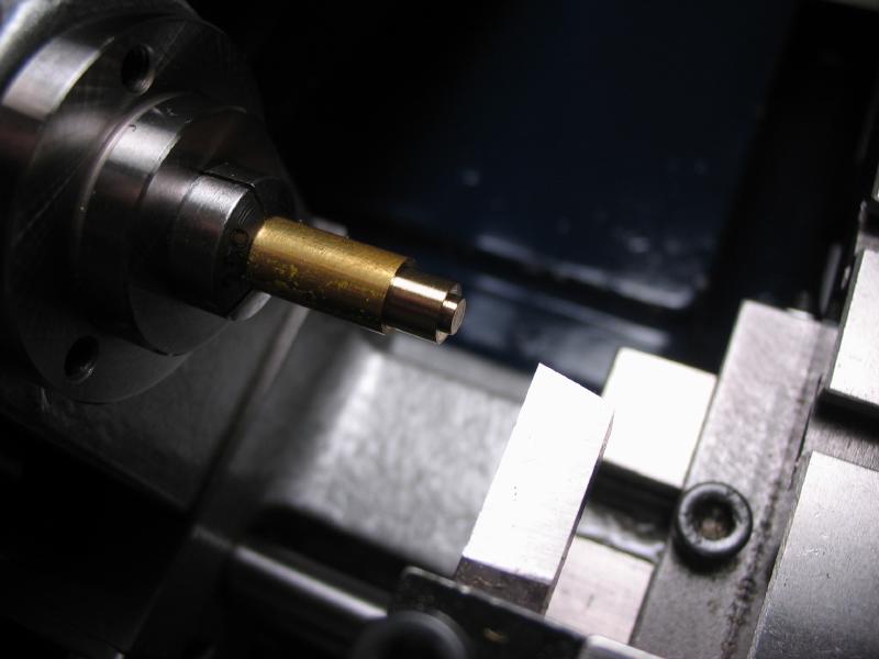
Starting with 4mm O-1 drill rod (3mm could have been used), the largest diameter (2.4mm) is turned. Then the shoulder for the bridge is turned (1.6mm diameter x 0.5mm deep). It is centered and drilled for the 1.2mm tap (1.0mm).
Link below is the full dimensions of the carriage bridge and pillars.
| tourbillon_carriage_bridge.pdf |
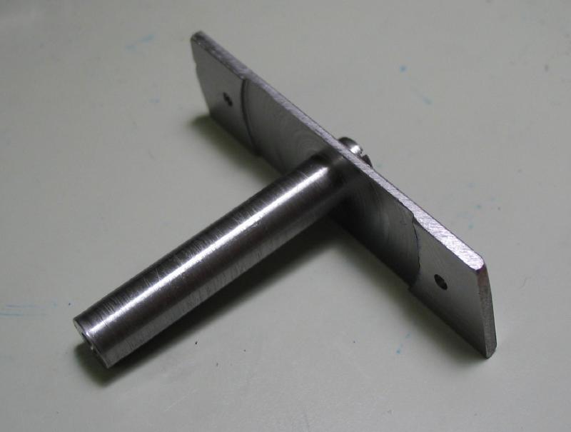
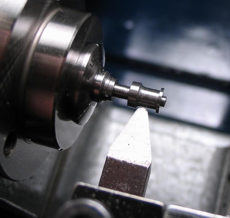
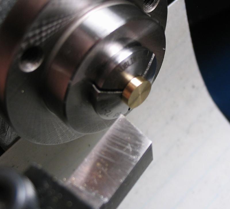
The base shoulder is turned and the post is parted off.
The post is reversed and held in a 2.4mm collet and the threaded base portion turned to size for the 1.5mm die (1.47mm). This portion is a bit oversized with a small tapered end to assist in the threading, after it is fit to the plate it can be shortened.
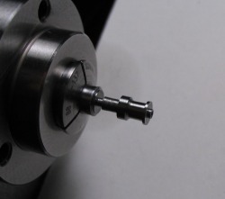
A waisted portion is formed, following the dimensions. The pillar is then polished.
Just to try an alternative, when making the second pillar, I started with 3mm drill rod, center drilled, drilled and tapped for 1.2mm.
I then turned the boss for the bridge, turned to full diameter and used the first pillar as a reference to form the length. It was then finished as before.
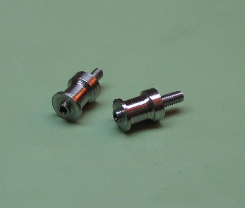
After fitting to the mainplate, the threaded shaft can be shortened and the pillar is then hardened, tempered to blue, and repolished. Of course, two must be made for this particular arrangement. One is marked, and shall from then on be assigned to a particular hole in the plate (which can also be marked for reference).
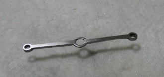
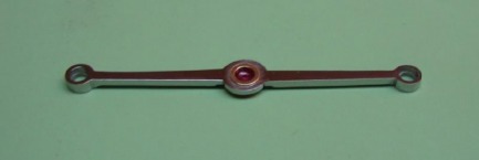
The Carriage Bridge
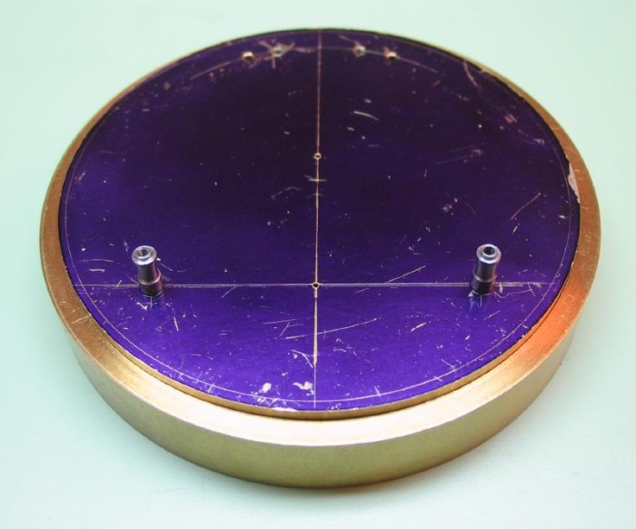
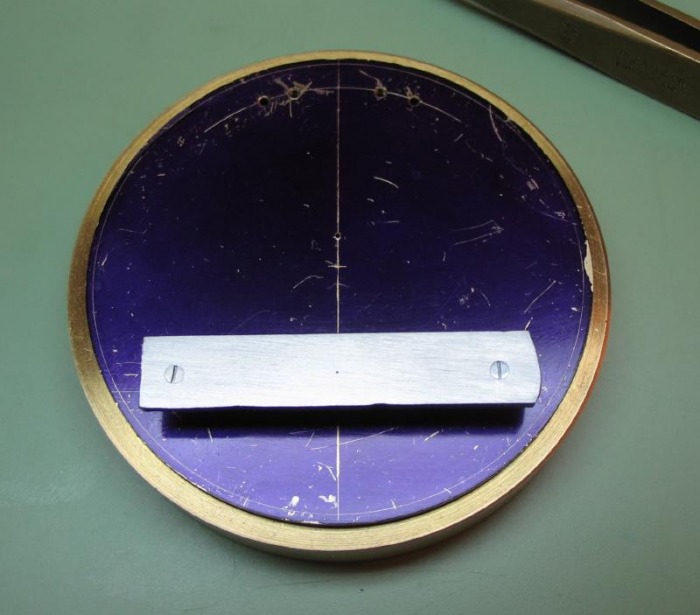
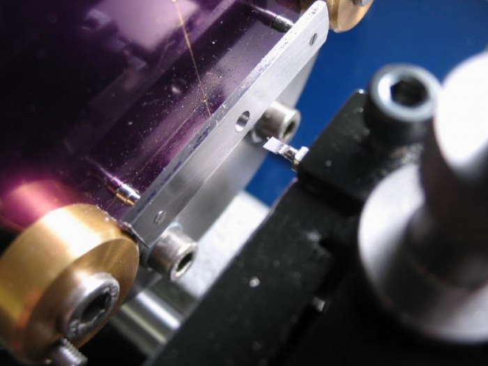
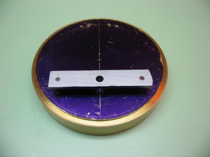
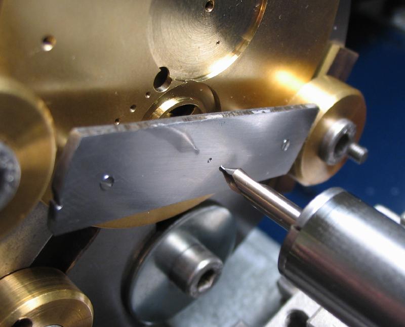
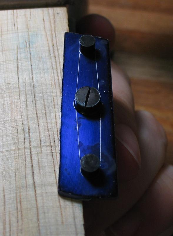
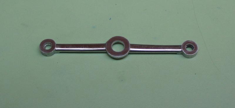
The bridge is made from 1/16" O-1 gauge plate. Daniels suggests a metric thickness of 1.5mm, after lapping the surface of the gauge plate it will be close to that and any variation can be accounted for. A section is cut out, about 10 x 50 mm , and coated in layout blue. An approximate center is found (exact center will be determined later, in situ) and the locations for the pillar holes are scribed with the compass (radius of 16.5mm). With the compass set, the positions are also marked on the mainplate.
The mounting holes are drilled undersize and it is lapped smooth on 220 grit emery. One hole is broached to fit the marked pillar (a reference is made on the bridge as well). The other hole location is assured and broached to fit.
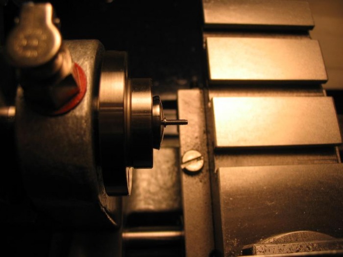
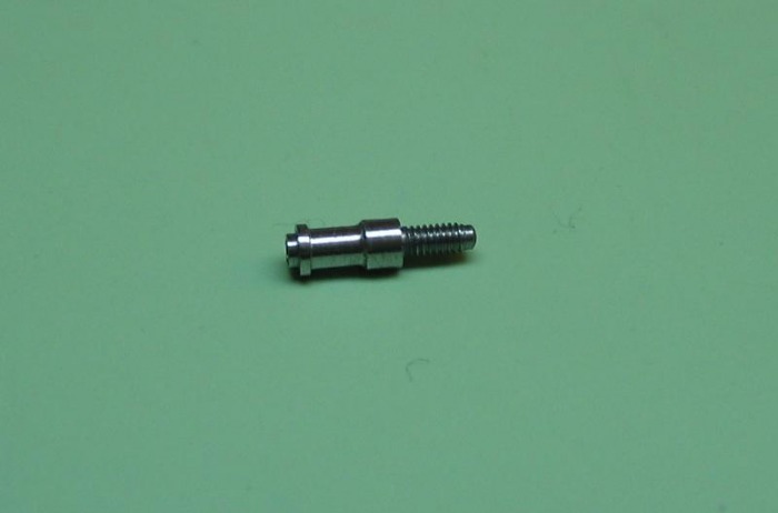
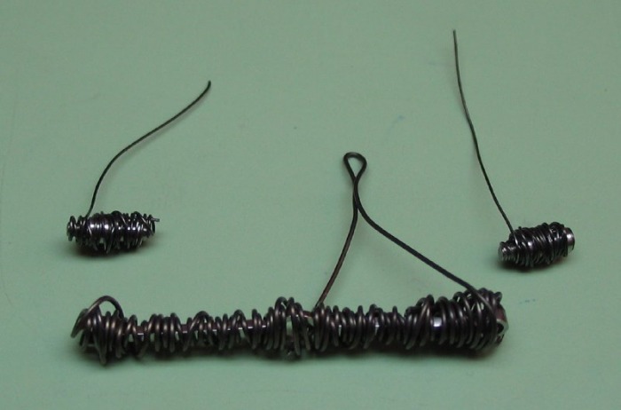
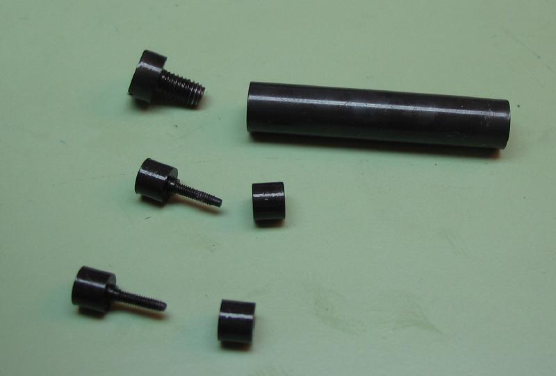
Screws need to be made to secure the bridge to the pillars. Daniels does not detail the type of screw, his drawing suggests a cheesehead type of screw which is only 0.3mm larger than the boss on the pillar. He does not mention counterboring or countersinking this dimension.
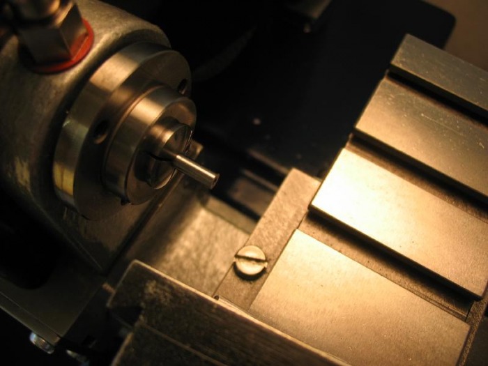
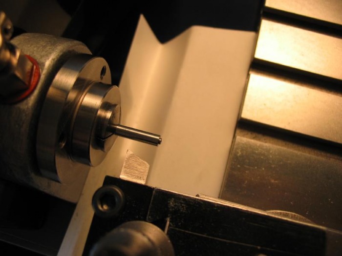
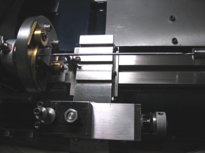
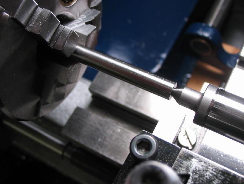
2mm O-1 drill rod turned to 1.17mm for the 1.2mm threading die.
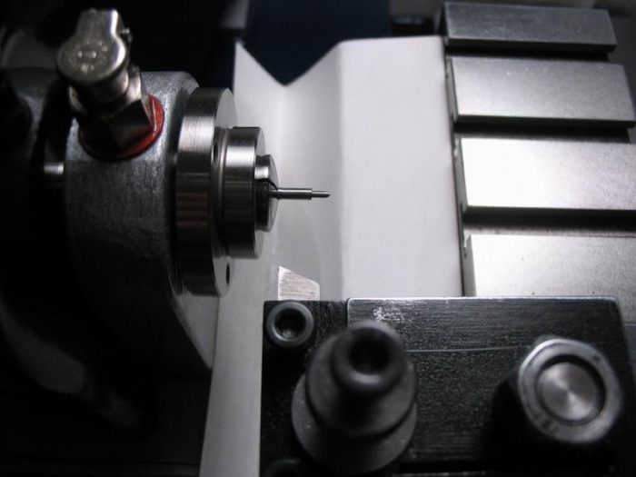
Threading in progress.

Finished screw, after forming the slot and polishing.

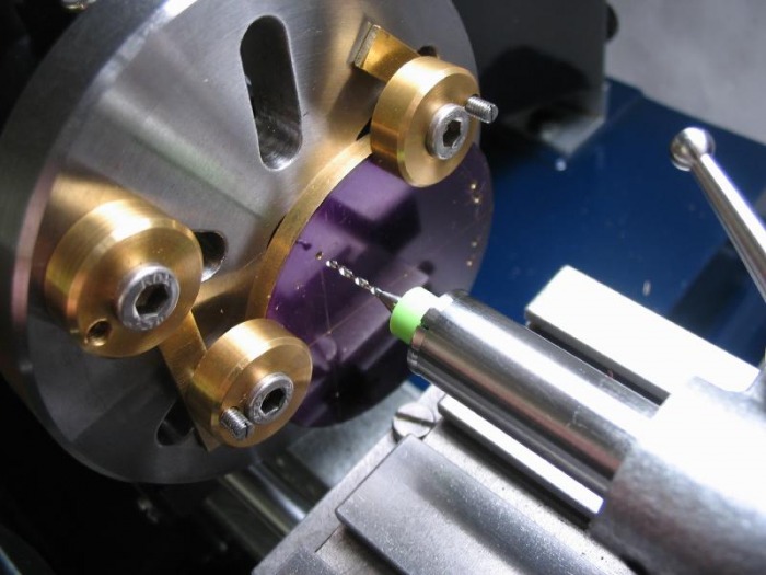
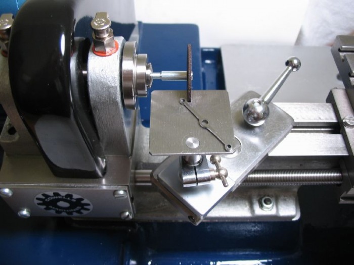
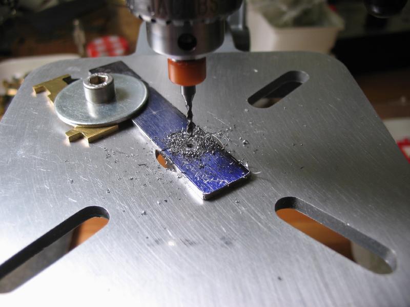
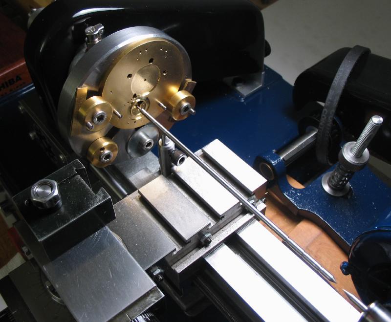
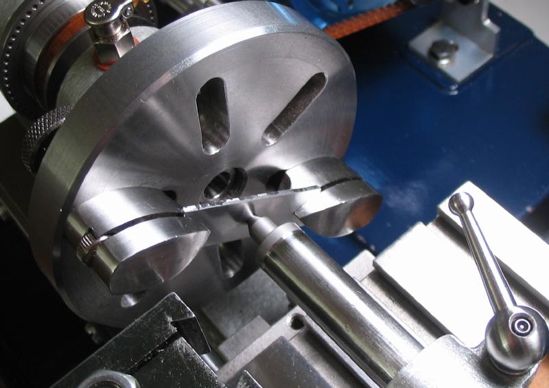
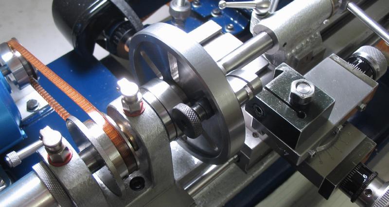
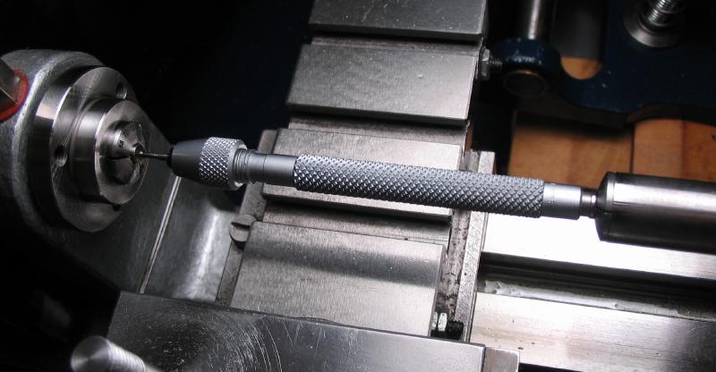
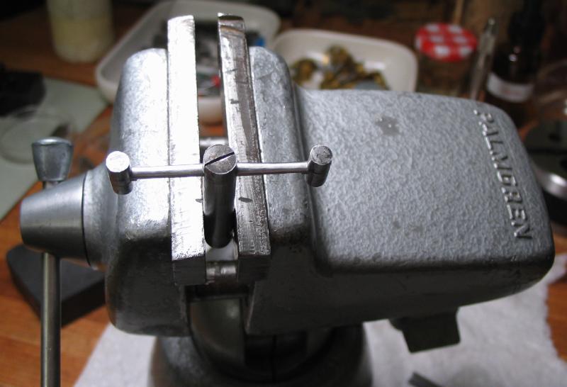
The mainplate is setup on the faceplate.
It requires a balancing weight.
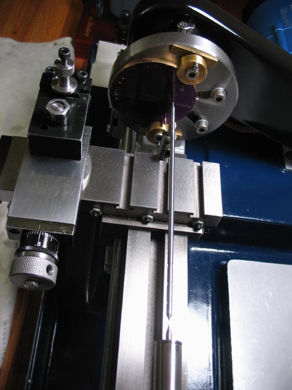
The pillar position is center drilled and then drilled 1.25mm for tapping 1.5mm
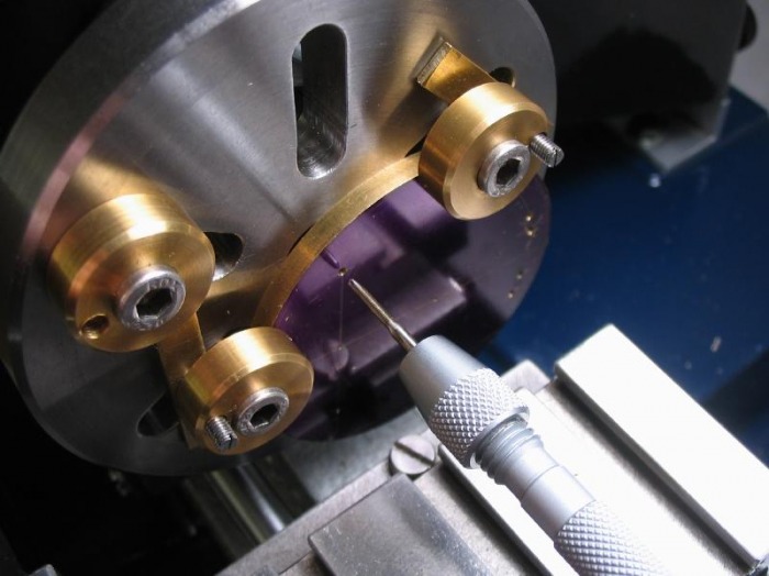
The hole can then be tapped, I used a pin vise steadied on an arbor in the tailstock
 |
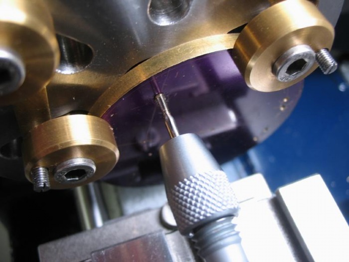 |
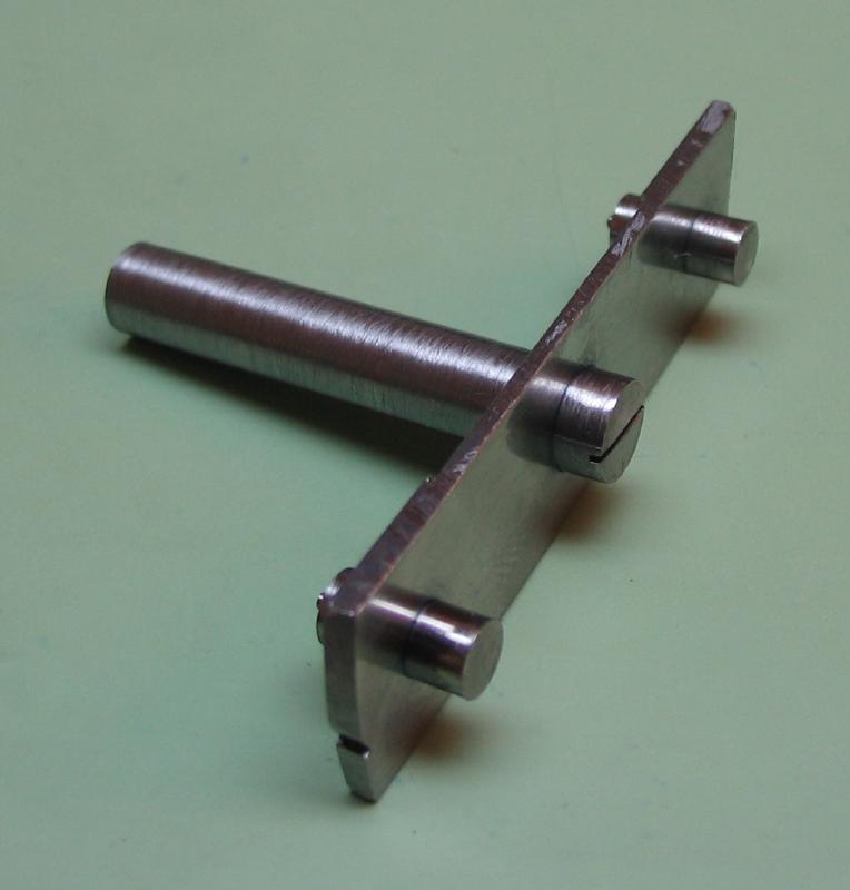
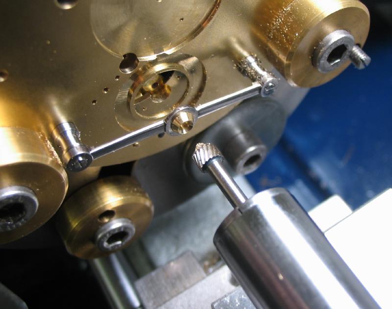
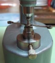
The pillars can be screwed into position.
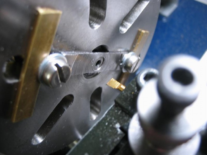
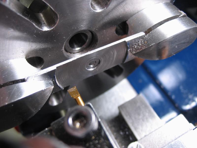
Counterboring the screw seats in the bridge with a carbide micro boring bar.

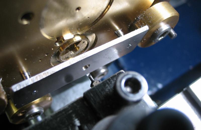
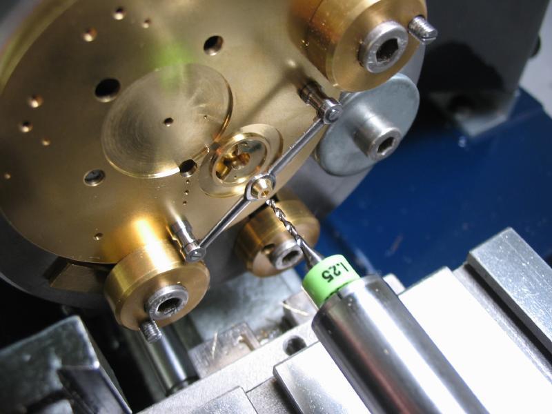
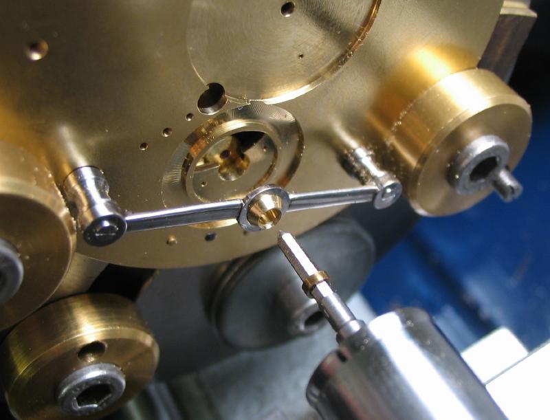
The rough bridge can be fastened to the pillars and screwed into position.
At this point the mainplate is centered to the carriage pivot position on the faceplate using a "wobble stick." See the toolmaking section on the fabrication of this gadget.
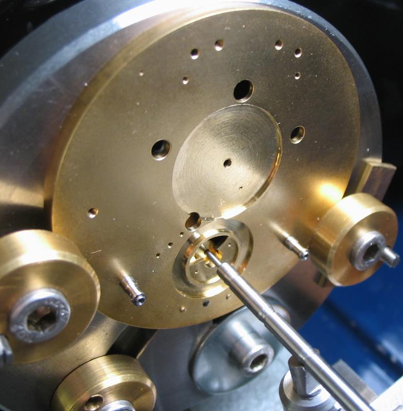
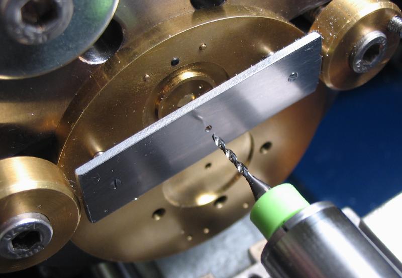
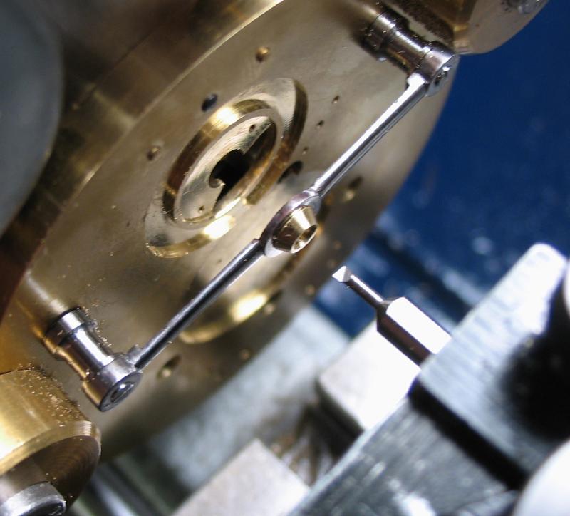
The bridge is secured and the center position made and drilled undersize (2.05mm) and then bored to 3mm for the jewel setting. A simple plug gauge was made in preparation to this step to check boring progress.
Drilled
Plug gauge.
Boring to 3mm with a Micro100 0.080" boring bar.
Boring complete.
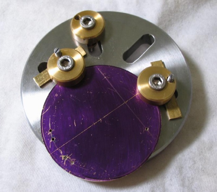
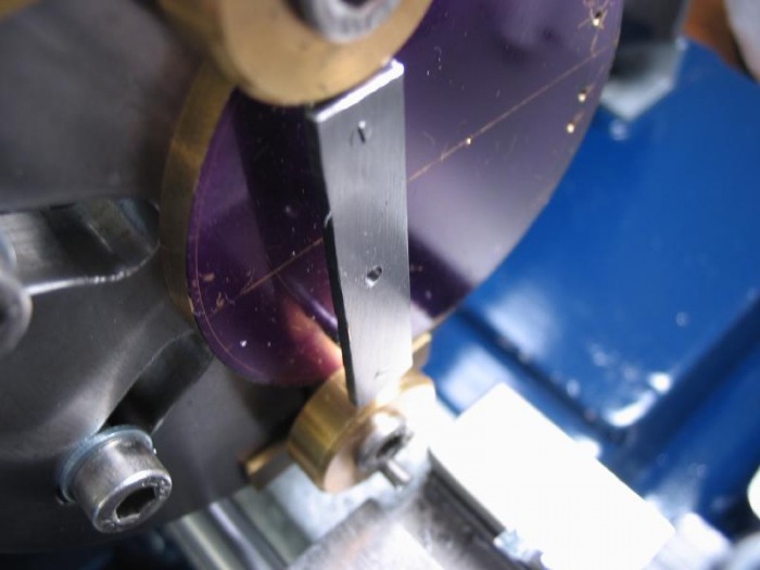
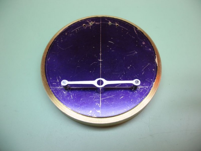
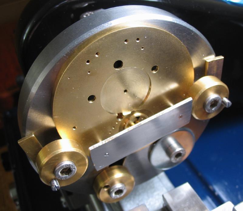
The bridge is removed and reversed onto the faceplate and recessed for clearence of the carriage components.
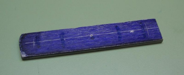
The basic outline of the bridge can then be scribed and cut out and filed to shape. Daniels describes the finishing of the bridge in manner which requires skilled hands to perform. Looking at the progression of his watches you can see that he began by leaving the bridge as flat piece of steel with a grained surface and over time developed a more lavish finishing (beveled, chamfered and highly polished arms of the bridge) to a very high standard. Although the latter is quite striking, I am content for the time being with a functional part, and any type of presentable finish.
 Daniels No. 4 |
 Daniels No. 8 |
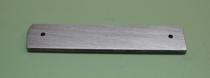
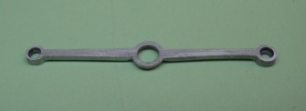
Machining complete
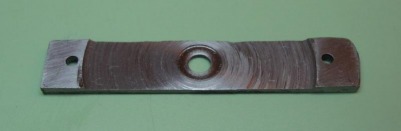
After sawing out and roughly filing to shape
I then set up the grinding table that I made previously (see toolmaking section). I used a aluminum oxide cutoff wheel as a grinding wheel to try to smooth and straighten the edges of the bridge. It also helped to round the ends. The center of the bridge stills needs a bit of work, however.
"Filing buttons"can be made to fit the bridge holes and provide a guide for forming the final shape. This technique is described in great detail in William Smith's book, "Clockmaking and Modelmaking Tools and Techniques."
The bridge can then be hardened and tempered. It was wrapped fairly snug in 1mm iron binding wire to help prevent any warping.
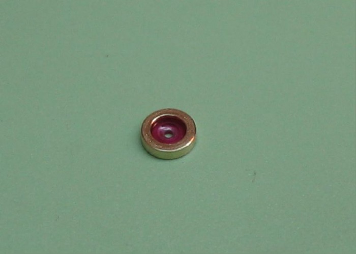
Jewel setting
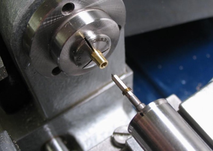
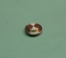
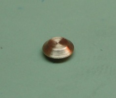
Brass rod (type 360) [it was left-over 3.5mm rod from a previous job] is turned down to friction fit the bridge. A pilot hole is drilled, 1.80mm. The hole is then broached open with a jewelling broach (from the Horia set - 1.98mm). It is then parted off and lightly polished up.

It is then off to the Horia jewelling press to have the stone installed. I am using a Seitz 30714 (200x50) center jewel for this pivot.
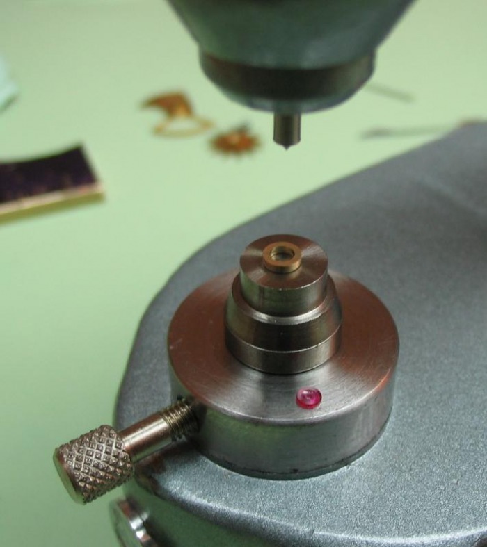
Jewel set flush with bottom of setting (micrometer zeroed on jewelling press)
 |
 |
The setting is then pressed into the bridge by the same method.
REMAKING the Bridge ...
I make a couple changes to the method above, but overall it is the same procedure.
A strip of 1/16" O-1 gauge plate was sawed out (about 60mm x 10mm). Screw positions laid out, punched, and drilled undersize.
The plate is counterbored for the screw heads and fit to the movement by broaching the holes to pass the threads. The extra length was useful for holding with the faceplate clamps.
The plate is shortened to fit on the faceplate while mounted on movement. It is setup on the lathe with wobble stick.
 |
 |
The carriage position is center-drilled, drilled, and bored to the final diameter using a plug gauge to monitor progress (made previously).

The plate is removed from the movement and mounted on the faceplate to bore the recesses on the underside. These were reduced in diameter compared to the previous. I am able to use the watchmaker's lathe faceplate clamps on the Cowells faceplate, which hold the bridge much more securely.
 |
 |
Safety plugs were made to fit the center and both screw positions. I did a better job of making these this time around. Time consuming as it was, I am hoping it will assist in a better final product. Turned from O-1 steel and hardened in oil, they are left in the full hard condition.
 |
 |
 |
 |
The general shape is sawed out and with safeties in place, the filing can begin.
I decided to have a try at beveling the arms of the bridge. This is the style and form that I would prefer, and one can never start practicing such a technique too soon. The bridge was held in the vise with the safeties in place, and filed with a No.2 barrett file, followed by a No. 4, then a No.6, followed by emery paste on mild steel, green rouge on steel, and diamantine on brass. It still needs hardening and tempering and then repolishing, but once again, extra practice is never time wasted.
A couple photos at different stages of filing.
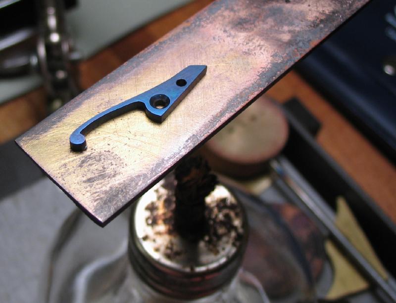
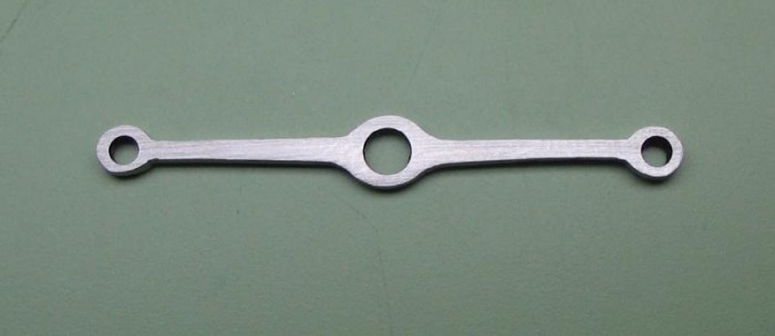
Wrapped in iron wire, hardened in oil, polished, tempered to blue, and given a final polish.
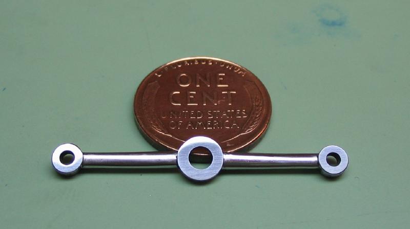
With the new bridge made, it did not look quite right after mounting it on the pillars. I made the center and screw position parts of the bridge a larger diameter than previously. So I decided a new pair of pillars were in order as well. The basic design will be the same, but the main body will be a larger diameter, 4mm with a 3mm waist. For a good finish I started with 5mm O-1 drill rod and turned down to 4mm. The same methods were used as in the beginning of this page. Turn boss, drill, tap (1.2mm), and turn waist. Reverse, turn and thread 1.5mm. Repeat.

Reduce the threaded post length to be flush with the mainplate.
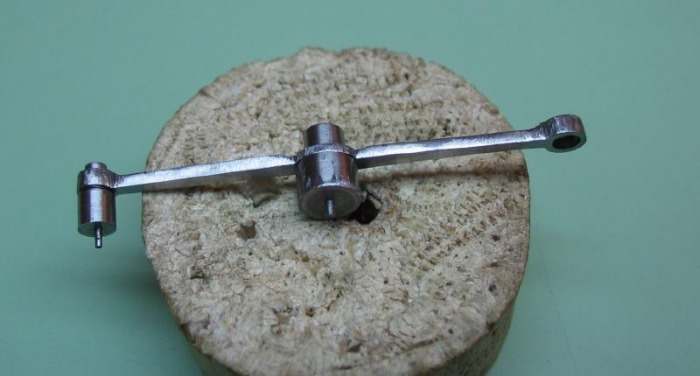
The collet holder, simple depth gauge, cup bur, and an old file work well.

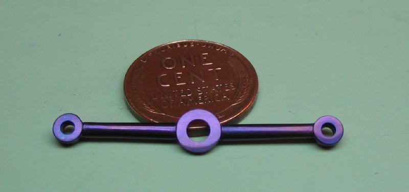
Polish, harden, polish, temper, and polish...

A mistake was made while making the first bridge, I intended to correct it, but then decided to remake the bridge completely. The mistake lies in the jewel bearing. I made the bearing separately, and it was made perfectly concentric. However, it is more accurate to make a jewel bearing blank, fit it to the bridge, and then center the movement back onto the faceplate (centering on the lower carriage pivot jewel), and drill-bore-broach the jewel hole in the upper bearing. The resulting jewel hole may not be perfectly concentric with the diameter of the bearing, however is it far more important that the pivots be perfectly upright.
I therefore made a jewel bearing blank to fit the bridge. This one is a little different in design, it has a flange and is beveled and will chamfered while boring the jewel hole.
 |
 |
Setting up on the faceplate with the wobble stick.
This is where having a second faceplate would be handy, the mainplate could have been left in place while making the bridge using a second faceplate.

Center drill.

Drill to clear boring bar.
Bore to jewel diameter minus 0.05mm.
(2.00 - 0.05 = 1.95mm)
Plug gauge was made to monitor progress.
Setting bur used to chamfer the opening.
Jewelling broach used to fit jewel (1.98mm).
Jewel set using press with micrometer, set 0.05mm below flush.
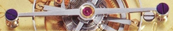
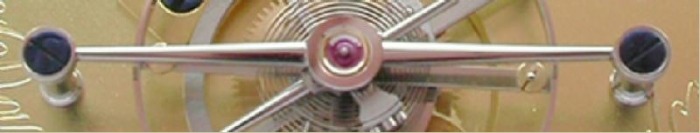
Finished bridge and test fit of tourbillon carriage, success !