Care and Maintenance of the Cowells 90 CW
Maintaining the Cowells 90 lathe is rather straightforward, and I thought readers may wish to see some of the various components of the lathe while disassembled, since this information cannot be found elsewhere, that I am aware.
At the conclusion of a machining project, I sweep up the swarf and metal chips using a brush. I found a German made, goat-hair, goldsmith's brush that is a convenient size to use on the Cowells. A small paint brush and disposable 'flux' brushes come in handy while working on small jobs and to sweep away swarf in tight cervices.

I always oil moving parts before starting any work, and wipe the machine down and re-oil after use. I periodically give the machine a coating of light-weight oil (Nye Oil) on all exposed steel/iron surfaces to prevent rust. If I know it will be a while until the lathe will be used again, I usually cover the lathe with a thin cotton cloth. The cotton will absorb oil, but is not a concern for a short period of time. It helps keep dust and debris away.

Most of the text below is from the instructions included with the lathe.
General Maintenance Rules
1. Pay attention to lubrication at all times.
2. Keep working surfaces clear of swarf as much as possible. Swarf is abrasive and in some cases can absorb oil, resulting in 'drying out' of a previously lubricated surface.
3. Always clean the machine, re-oil after use, particularly if water soluble oils or paraffin have been used as cutting lubricants. These products can cause rust.
4. Do not use abrasive fluids (metal polish etc.,) to clean the machine. Remove any swarf with a soft brush - wipe with a clean dry cloth and re-oil.
5. Never leave the machine unused for long periods with the belts tensioned. Always release the belt tension at the end of working period.
NOTE : These rules should also be applied to machine accessories.
General Notes on Lubrication
Oiling points are provided for the headstock and leadscrew bearings. All other working surfaces such as slides, leadscrews, etc., are lubricated by applying oil directly to the surface. Use a good quality SAE 20 or 30 grade of machine oil such as Myford NUTO, for all lubrication. Do not use 'sewing machine' type oils of the 3 in 1 kind. These are for light duty only and are not suitable for the Cowells machine. I purchased a quantity of Esso NUTO H32 (equal to Myford Nuto) for the headstock spindle and use NyOil (a light highly refined mineral oil) for general lubrication.
Frequency of lubrication is dependent upon the duty of the machine but:
(a) Always lubricate before use and after cleaning down.
(b) During prolonged machining operations lubricate at regular intervals paying particular attention to the headstock oil cups. I usually top off the headstock oil cups about once an hour or so when working for long periods of time.
Disassembly
First the compound slide is removed, to remove the compound slide assembly, remove the two screws to allow the angle pins to move outwards. Then, rotate the unit back and forth, pulling upwards to push the pins clear. Note that the assembly is a tight fit and some force is required to remove it.
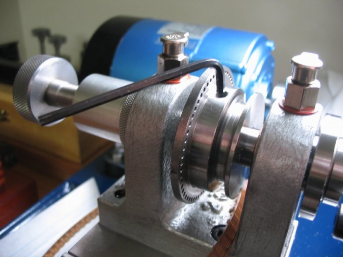
The arrow is pointing to one of the set-screws being removed with a hex driver
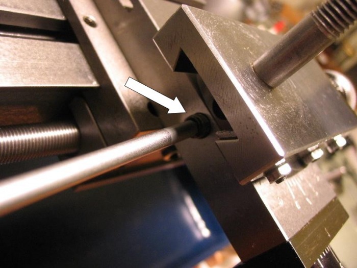
The compound slide has a permanent mounting bolt for attaching the tool posts, etc. and the slide attaches to a dovetailed mount (with gib strip) that pivots in the cross side.
 |
 |
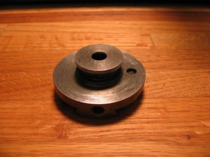
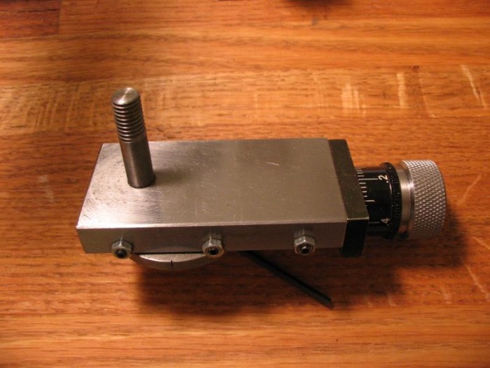
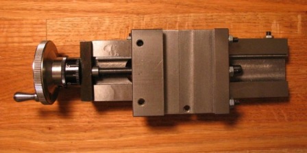
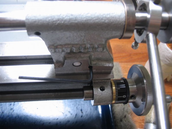
To remove the cross slide carriage from the lathe bed, the leadscrew handwheel must be removed first because it is in the way. The handwheel and thimble assembly are pulled off the leadscrew arbor after loosening the set-screw and removing the slotted screw that fastens the handwheel to the lead screw.
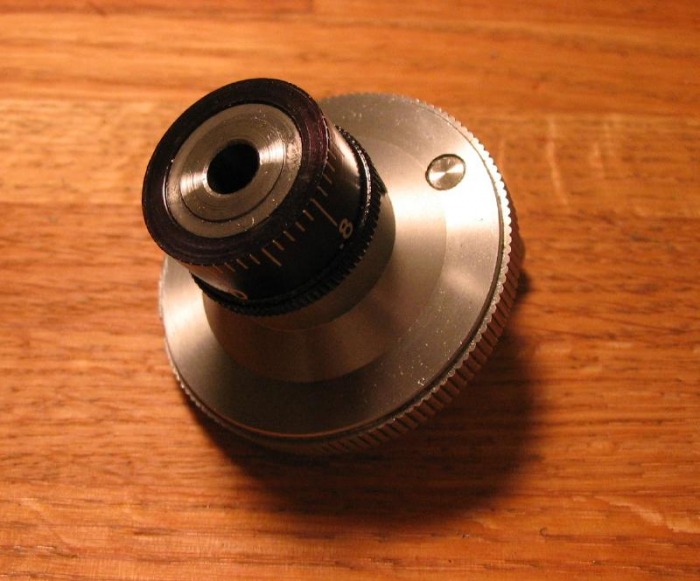
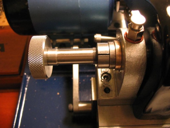
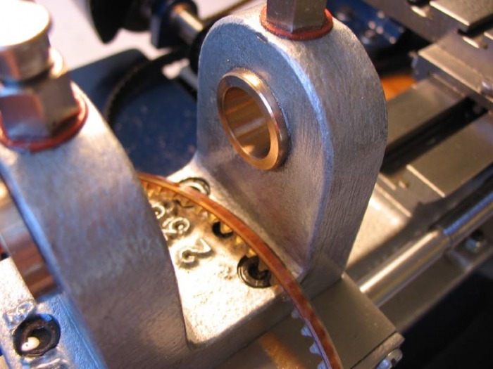
You can see the handwheel has an Oilite bearing on its mount which also acts as the pointer for the dial thimble. Cowells make use of Oilite bearing in a number of different places on the lathe. They are made in Ipswich England (keeping with Cowells' "Made in England" philosophy) and theoretically do not require lubrication, however, I find myself being more comfortable with adding a drop of oil to these contact points as well. Also in the photo below you can see the oil port on the lathe bed bracket which holds the lead screw in place. A drop or two of lightweight oil gets added here periodically to keep the leadscrew bearing lubricated. I use NyOil as my general purpose lubricant for the bed, slides and handwheels, screws, etc, (everything but the headstock spindle).

To disengage the cross slide carriage from the leadscrew the apron must be removed. This is bolted onto the saddle.
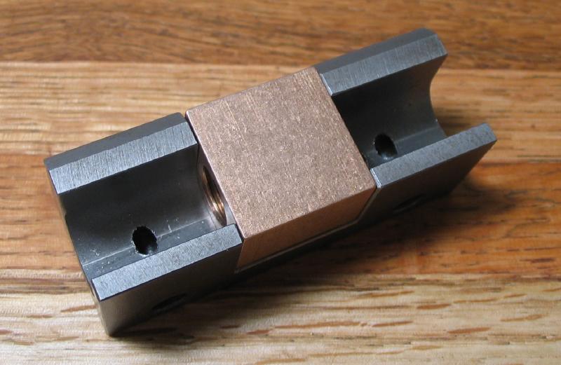
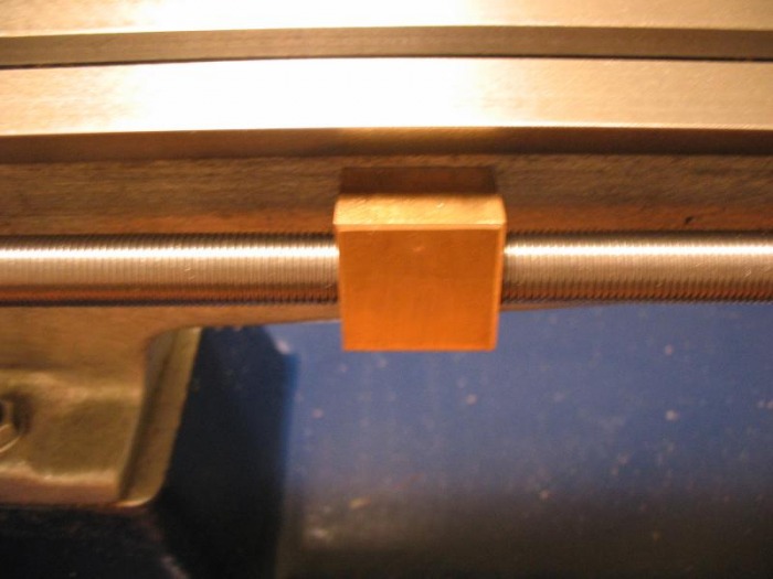
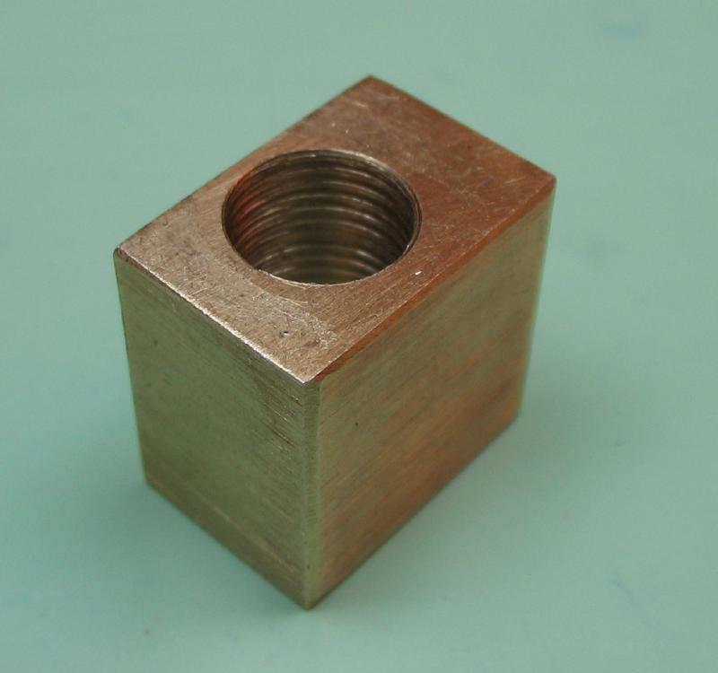
Here are a couple photos of the apron itself, it engages with the brass/bronze follower block that is threaded to the leadscrew and has an adjustment screw. This is the same apron used on the 90ME lathe and therefore has a milled slot and tapped hole for attaching the auto-traverse stop arm.
 |
 |
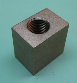
The leadscrew follower nut
The cross slide and saddle can then be slid off the lathe bed.
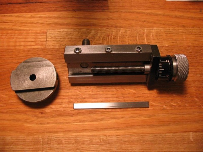
Here is the cross slide, by itself, with its gib strip laying next to it. I simply brush the swarf away and wipe it down with with an oily cotton rag. The screw gets some extra attention to remove the build up that collects on all the screws.
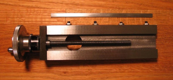
Everything is liberally coated in NyOil, and the gib strip is put back into place.
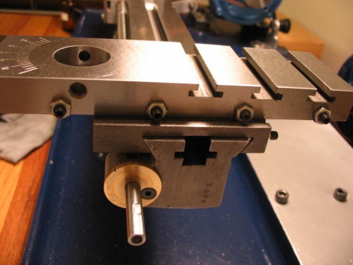
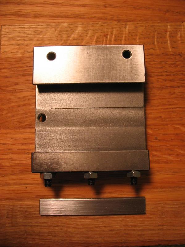
Here is the cross slide saddle. This is the part which rides along the lathe bed and connects to the main leadscrew. In the photo you can see the top of the saddle including the dovetail which mates with the cross slide, the milled slot that allows the cross slide gib adjusting screw nuts to pass along, and three tapped holes. The two holes at the top are for attaching the leadscrew apron and the tapped hole to the right is for mounting various attachments, such as the roller filing rest or traveling steady.
 |
 |
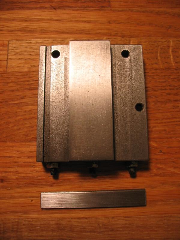
Cross slide mounted back onto the saddle, in the following photos you can see the underside of the saddle. This side mounts onto the lathe bed, and therefore, has its own gib and adjusting screws.
General Adjustment Notes
Belt Adjustment
Gib Strips
Gib strips are steel inserts fitted between the faces of sliding parts to provide accurate control of the fit of the parts, thus allowing for initial setting and compensation for wear. They are positioned and secured by means of screws and locknuts and are used on the compound slide, cross slide and saddle. To adjust any of the gib strips, slacken the appropriate locknuts and then set each screw in turn to achieve a good slide action, without sideplay and without undue loading of the feedscrew. Tighten the locknut as each screw is set to ensure that there will be no further movement when the effect of the setting is checked. Readjust each screw if necessary to achieve a good slide action for the whole of the travel.
The dimensions of the adjustment screws and nuts are as follows:
Topslide Grub Screws : 1.5 mm
Topslide Locking Nuts : 5.5 mm
Cross Slide Grub Screws : 2.0 mm
Cross Slide Locking Nuts : 7.0 mm
Leadscrew Follower Grub Screw : 2.0 mm
Leadscrew Follower Locking Nut : 7.0 mm
Leadscrew Backlash
Leadscrew backlash is controlled by the position of the handwheel on the leadscrew extension. To adjust, slacken the screw in the side of the handwheel and then turn the slotted screw in the front of the handwheel clockwise until the backlash is 5 divisions or less of the graduations. Tighten the screw in the side of the handwheel. Note that it is impossible to eliminate backlash completely and that any backlash is always accounted for when performing machining operations.
Headstock Spindle Bearings
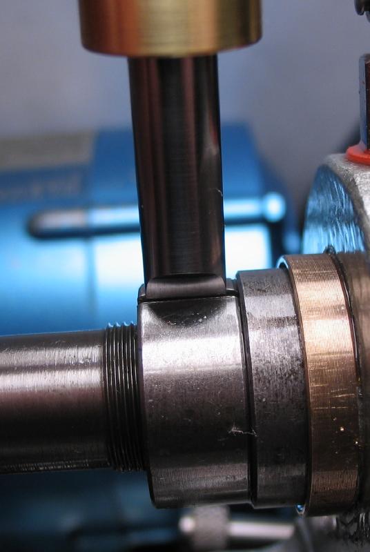
The CW Lathe has tapered cone bearings. Adjustment is provided at the rear steel cone by adjustment of the split adjuster nut. This is easily done with a small screwdriver to splay the nut and tighten or loosen as appropriate.
Remove aluminum dust cap

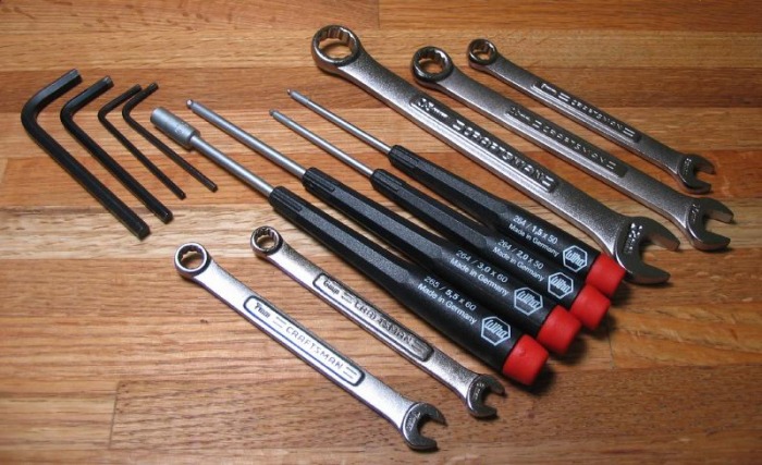
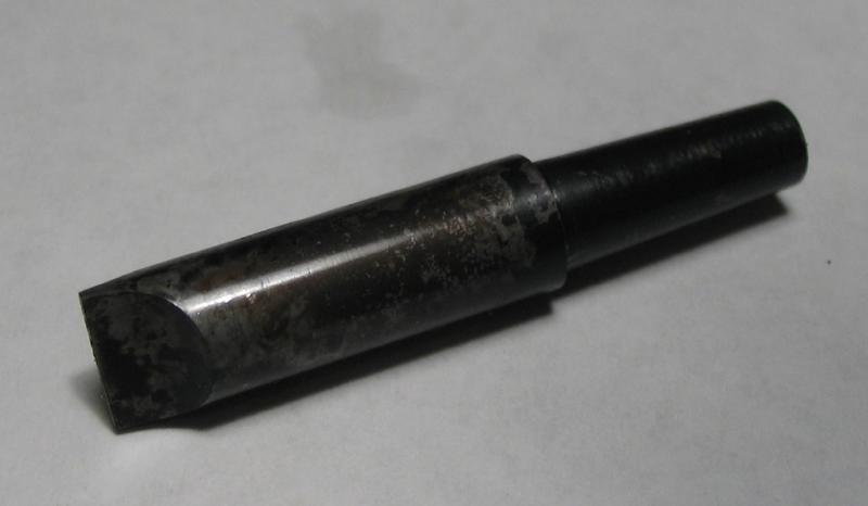
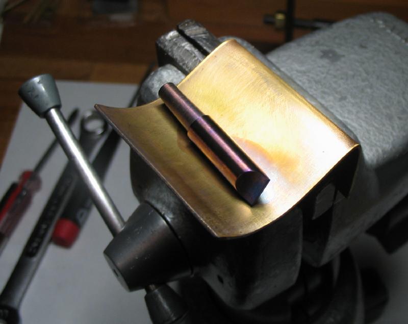
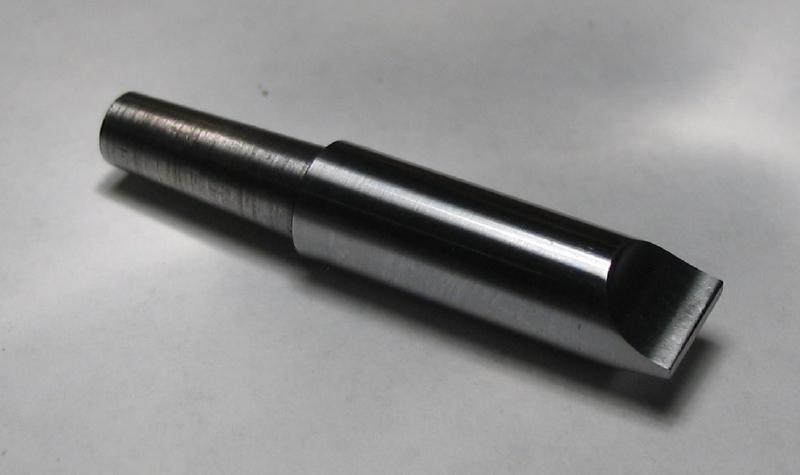
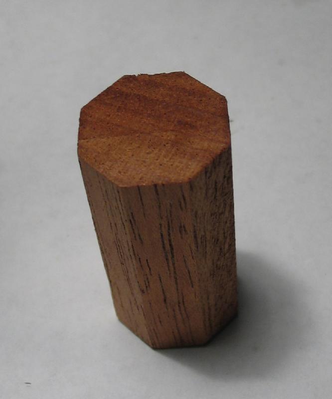
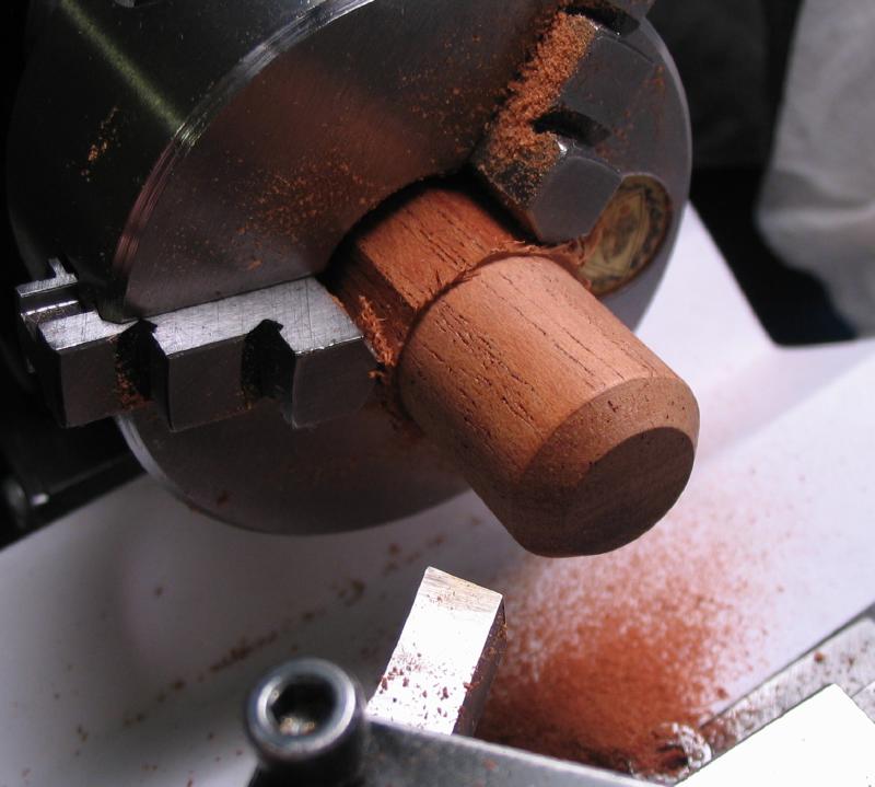
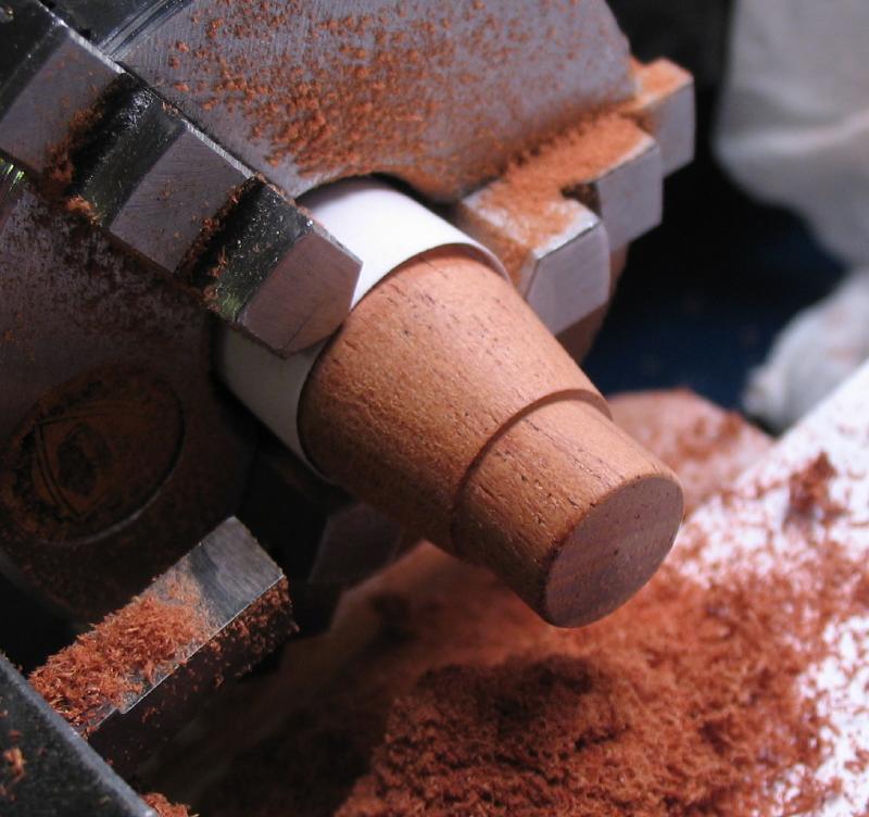
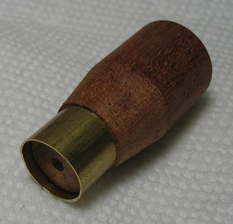
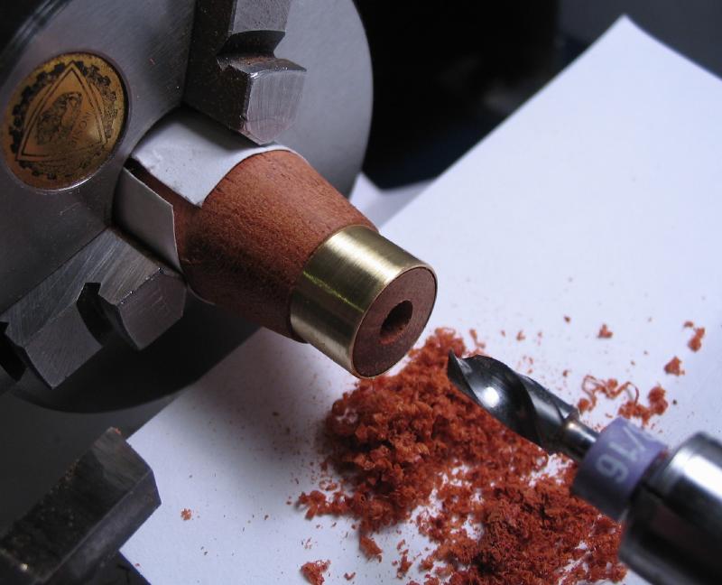
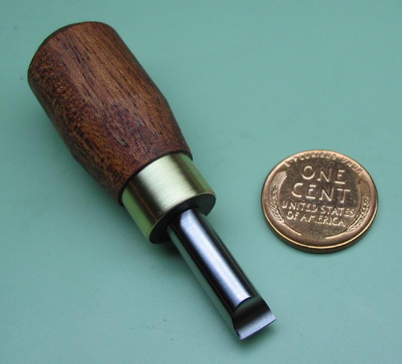
I always used the nearest screwdriver to splay adjustable split-nut for tightening/loosening or removing for attaching the dividing plate. A dedicated tool was made to fit the split nut. It was started from a short length of 1/4" oil hardening drill rod. One end was turned to a taper and the reverse milled with a 3/8" ball-endmill. It was hardened and tempered to a dark blue and then re-polished. The handle was made from a short length of 3/4" cherry "pen blank." It was turned round and chamfered, and the reverse end turned to fit 1/2" brass tubing and then a 10 degree taper. After hammering on the tubing collar, it was turned to match the wood. The handle was drilled 3/16" to match the diameter of the bit at about half way up the taper). Finally, the bit held in a vise and the handle hammered on, and the wood rubbed with mineral oil.
|

|
|
|
|
|
|
|
|
|
|
|
The pulley is loosened by its set screw and the headstock spindle can be pulled out through the front.
The various components
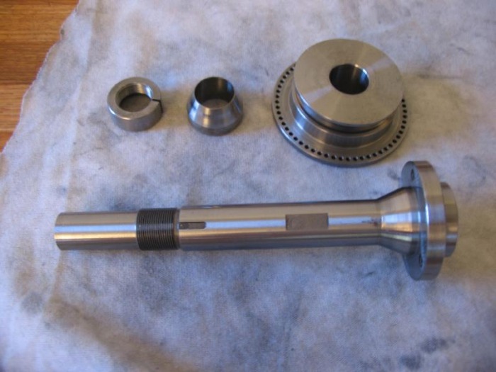
You can see the phosphor bronze cone bearings
Tailstock Alignment or Tailstock Set Over.
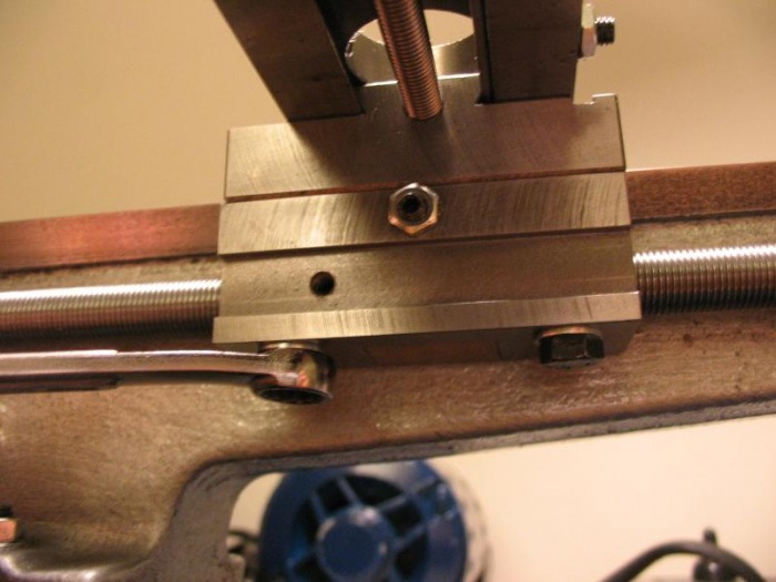
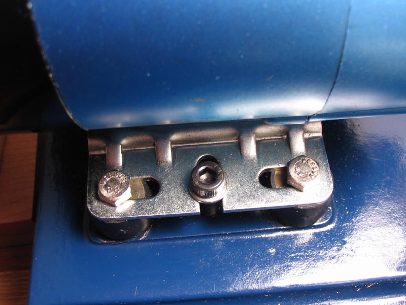
The tailstock centre can be moved out of alignment with the lathe centre line to enable taper turning to be carried out. The total movement is limited to 6mm and this method of taper turning is normally restricted to very small angles. To set the tailstock over: a) Release the clamp lever at the rear of the tailstock body. b) Using the two screws (one at the front, and one at the back of the tailstock body) move the body sideways on its base alternately slackening one screw and tightening the other until the desired amount of set over, in the desired direction, is obtained. The tailstock can then be used in the normal way except that the parts turned will have a taper in diameter equal to twice the amount of set over. To set the tailstock back to its centre position repeat the operations in (a) and (b) but in the reverse direction, using a test bar and dial test indicator to obtain accurate alignment. Alternatively, alignment can be set by turning the ends of a bar between centres to check the setting. The setting is correct when the diameter obtained at each end of the bar is the same FOR THE SAME TOOL SETTING.
Another method of checking tailstock alignment described in machinist texts is to use a test bar. The test bar is fairly simple, and can be reused (an advantage to the method above). It is made from a length of drill rod, which is turned between centers at one end. This turned section is measured with a dial indicator mounted on the cross slide. The bar is reversed, and the measurement taken again at the other end, they should match, any discrepancies are corrected by tailstock adjustment.
Making and Using a Testbar
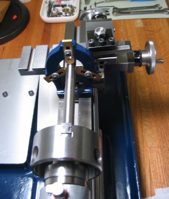
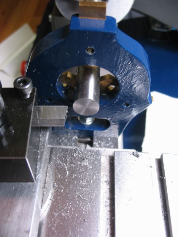
The testbar was made from 7/16" diameter O-1 drill rod, the diameter is not critical, the larger the better, I presume. The length is the longest that can fit on the lathe between centers, in this case about 120mm. The bar is mounted in the 3-jaw chuck and supported with the steady rest on the opposite end. The bar can then be faced and center drilled on each end. Note: this was my first use of the steady rest, and although I suspect it may not matter, I mounted it backwards!
Each end faced with right hand knife tool.
Each end is then center drilled.
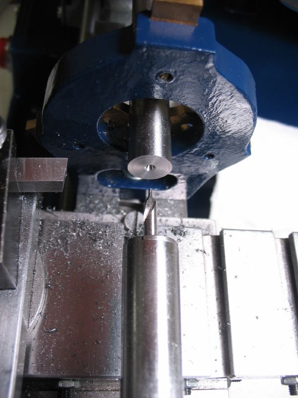
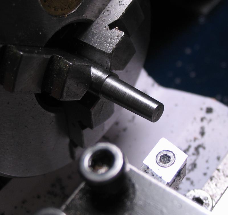
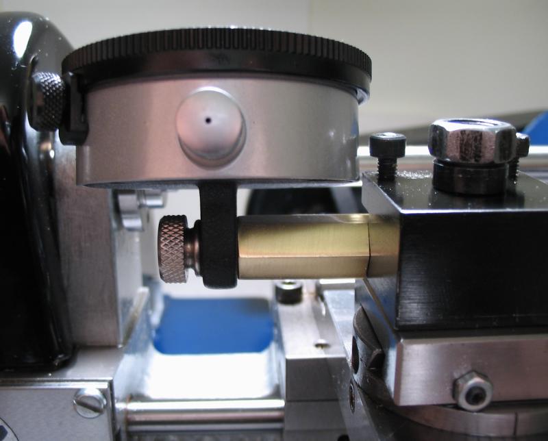
I then installed the faceplate and the zero-morse taper, male center into the chuck adapter and installed the rotating male center into the tailstock. A driving dog is mounted onto the testbar and dog-leg inserted into one of the slots of the faceplate. With the bar now mounted between centers, a portion of the tailstock end can be turned down until smooth and true.

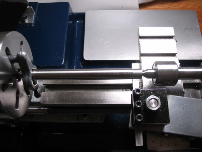
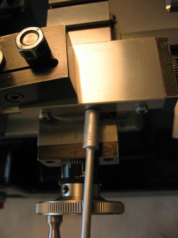
A plunger-type dial indicator is mounted onto the cross slide. I also removed the chuck adapter, faceplate and center and replaced them with the hardened collet shank center. The other may be just as accurate, but I chose this setup as it seemed more simplified.
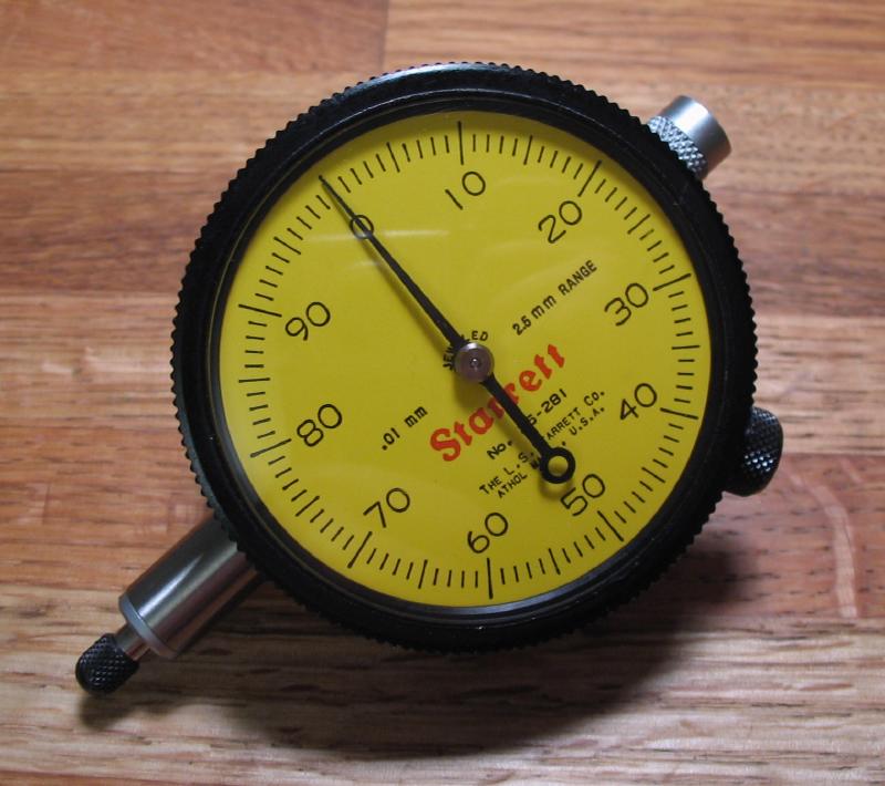
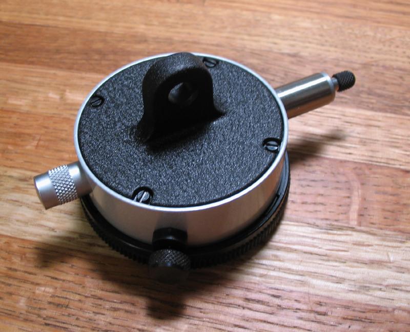
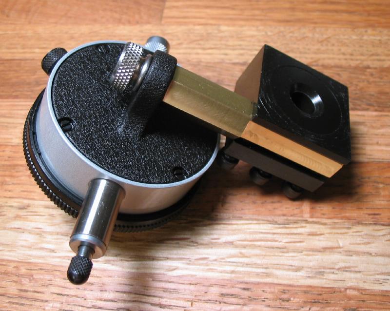
I am using a Starrett 25-281 Metric indicator (2.5mm x 0.01mm). The gauge has a 1/4" mounting flange on its back.
 |
 |
 |
 |
 |
 |
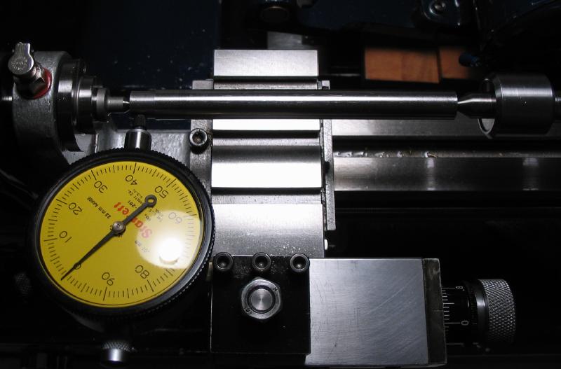
A measurement is taken at either the headstock or tailstock end, the bar flipped, and the measurement taken at the other end (on the turned portion of the bar, of course). These measurements should match, otherwise the tailstock is adjusted to correct the variation.
 |
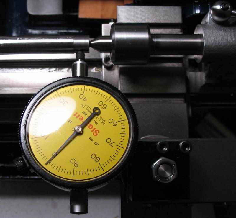 |
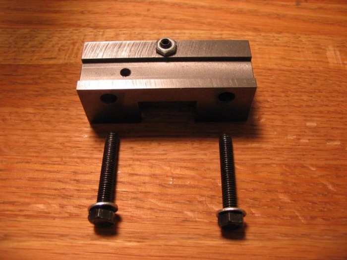
Correction is made by alternately adjusting the set screws in the base of the tailstock in order to move it in the direction needed to put it on center. Incidentally, I made this about a year or so after using the lathe, and it was about 0.10mm off center, so frequent checkups may be a good idea.
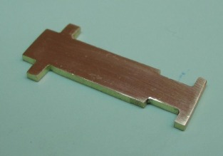
T-Slot clearer: I made a simple gadget to clear out the T-slots of the cross slide and the lathe bed. It is made from 1/16" brass plate and was simply scribed and sawn, and filed to shape. The cross slide slots measured 12mm wide, and 2mm deep, with a center width of 6mm. The bed t-slot is 9mm wide at the bottom and 3.5mm up to the T-slot, which is 16mm wide and 3mm deep.
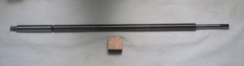
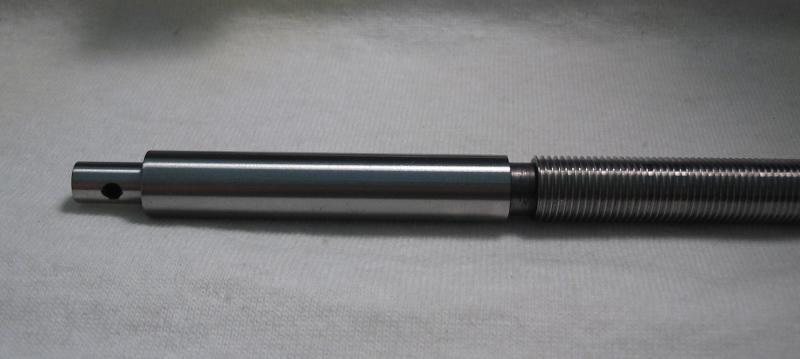
A New Leadscrew and Follower Nut
Cowells sent out a replacement leadscrew nut with the caveat that the fit may not be ideal. When building the machines a nut is selected that matches the leadscrew with the best fit possible. The replacement nut was a very tight fit, and ultimately it was decided to return the leadscrew to Cowells to have a new nut custom fitted. Although inconvenient to internationally ship parts back and forth, the fit of this nut to the leadscrew directly relates to the sensitivity of feed and backlash, etc in the handwheel.
In the future I will try to be more lenient with the tightness of the gib and the nut adjustment screw, which I have a hunch was the ultimate cause of the damage. Mr. Childs (at Cowells) suspected that some swarf may have made its way into the threads and caused the damage, therefore I shall be more diligent with keeping the leadscrew clean as well.
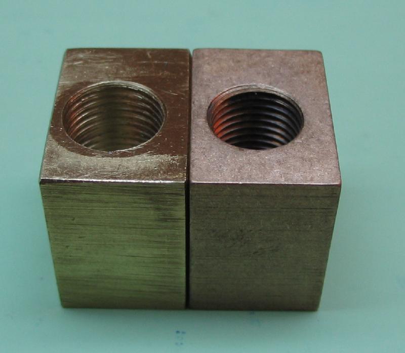
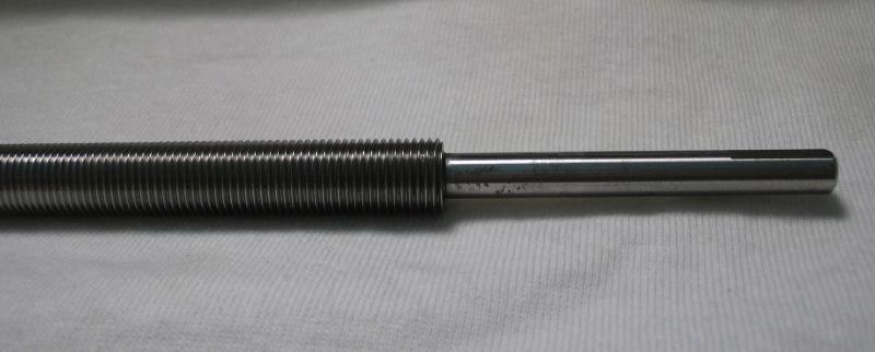
While there, I was then informed that the leadscrews currently being fitted to their machines have been improved since my machine was built. The current design consists of a hardened steel leadscrew with ground threads and a phosphor bronze follower nut. My previous leadscrew was unhardened with what appeared to be a brass nut. I decided this was an opportune moment to upgrade to this new version.
 |
 |
 |
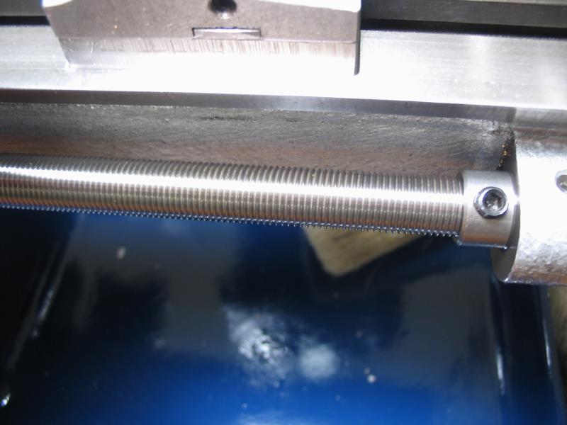 |
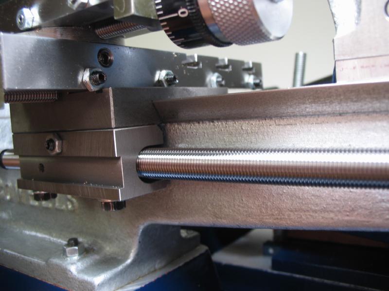
The new nut is slightly oversize and is lightly treated to some emery paper until it snugly fit the carriage apron.