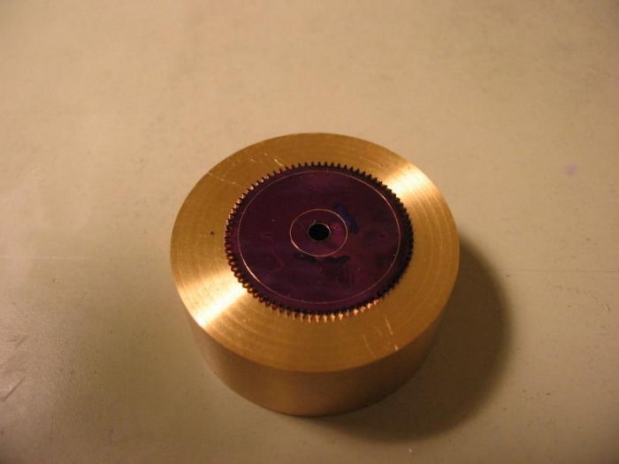
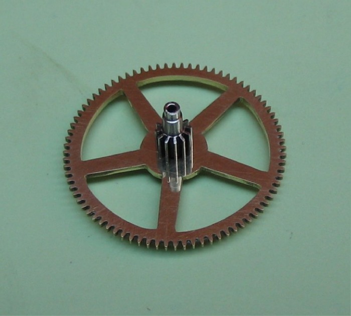
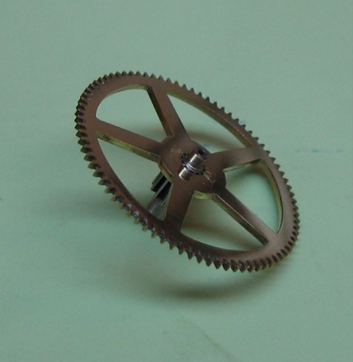
The Center Wheel
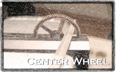
The next component to be made is the center wheel. After making the barrels, the initial steps of the center wheel are fairly simple. I decided against sawing out a disc from the brass plate, since this brass does not machine well. I parted off a disc from the type 360 - Ø1" brass rod, and attached it to one of my trusty super glue arbors and machined it to the basic dimensions.
Click link below for complete dimensions in PDF format
| centerwheel.pdf |
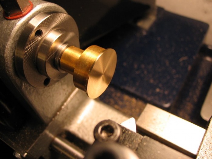
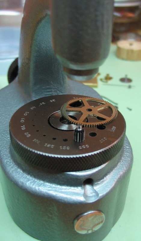
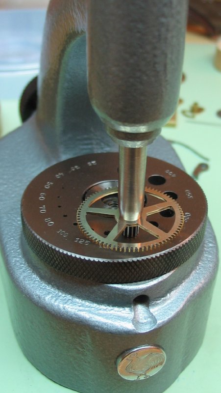
Then the lathe is setup for gear cutting, if you have read the post on making the barrel, this is the same setup, with the same module cutter. The center wheel is to have 80 teeth, and this again is found on the Cowells G2 index plate.
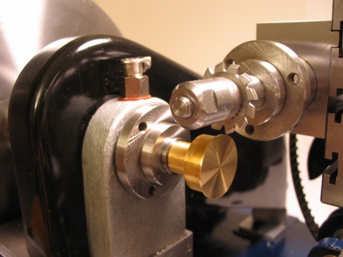
The hole for the pinion was drilled and bored to dimension. This was determined as 2.25mm, approximately 2/3rds the full diameter of the pinion. A gauge was made from 3mm drill rod, to test the hole diameter, since accurately measuring this with the calipers isn't feasible. The gauge was made with steps of 2.10 and 2.20 mm, to keep tabs on boring progress.
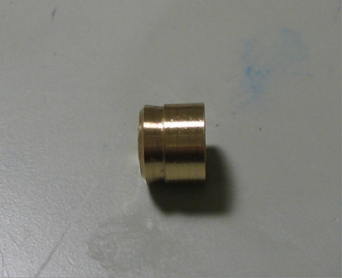
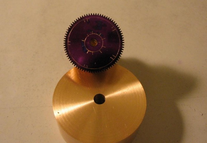
Following this it was simply removed from the arbor with a torch and cleaned up a bit.

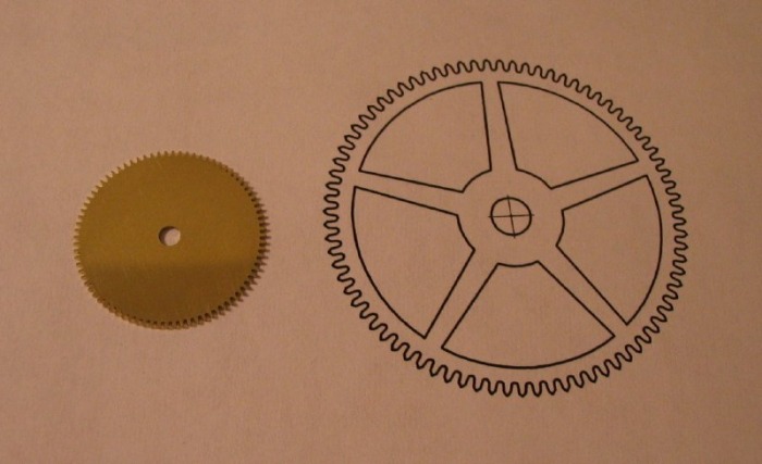
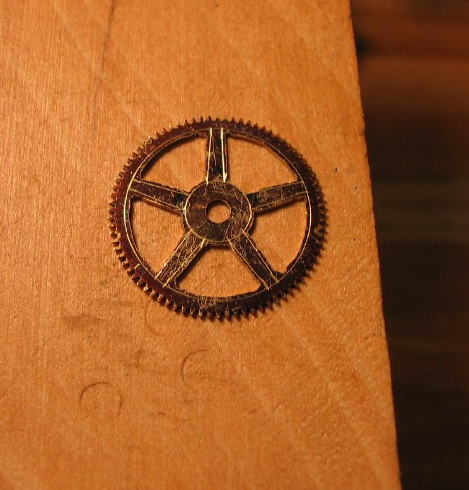
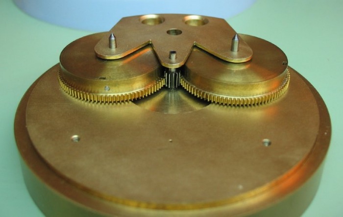
Next the wheel needs to be "crossed out," i.e. the spokes and such marked out and then cut away.
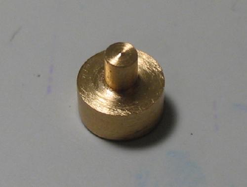
I started by making a little cheater; the hub is to be 6mm, so I turned down a piece of ¼" brass rod to 6mm and turned a 2.25mm spigot. This could then be inserted into the bore and the hub circle scribed around it. I then used a depthing tool to scribe the rim circle. I used the depthing tool since it has a trumpet runner, which can be used to center on the pinion bore, where a compass divider would not be able. The rim is 17.5mm in diameter.
 |
 |
 |
 |
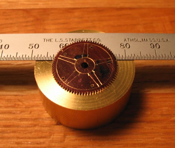
The marking out of the spokes was done in such an obtuse manner than I hardly feel that I should repeat it verbally.... I used the lathe with a series of indexing maneuvers to approximate my dimensions in an angular manner and marked the rim and hub circles with the scriber mounted in the tool post. Afterwards the points on the circles are connected with the scriber and a ruler. I felt the most critical point was to ensure even spacing, which appears to have been accomplished.
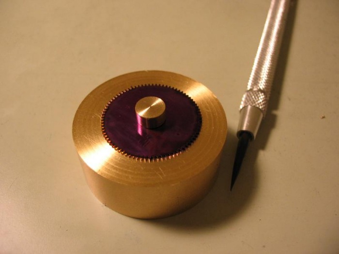
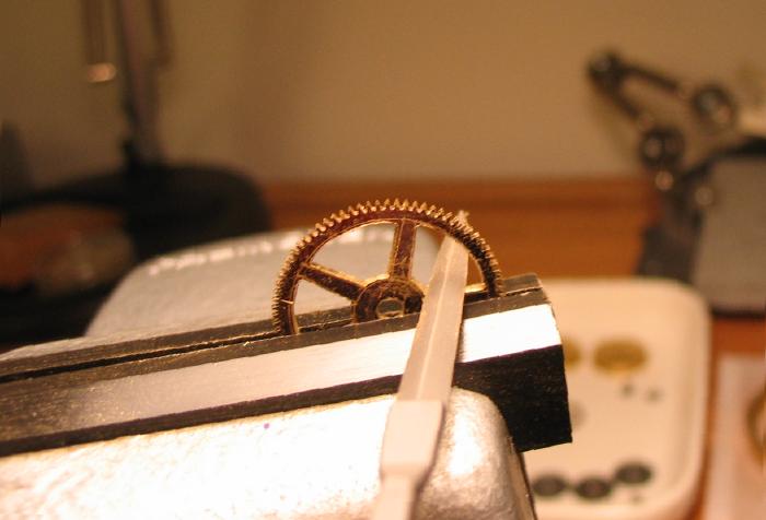
Shown here is the wheel resting on the bench pin after drilling the starting hole and cutting the space out with a 4/0 piercing saw.
Following the method described in 'Watchmaking' (especially figure 236) I ordered the necessary No. 6 escapement files and ground a safety edge on them using a coarse India stone. An as-is barrette file for the spoke arms, a safety barrette for curvature of the hub, a safety crossing for the rim and spoke-rim corner, and a safety square for the spoke-hub corner. I used the combination of a hand vise, a rubber block, and a adjustable Palmgren vise (now sold under the name Panavise) with nylon jaws. Not as simple as a task as it may appear, it required very small reductions and constantly double checking the effects.
The Center Pinion
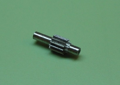
Making pinions seems to draw up some apprehension, from the various texts that discuss the subject, it seems to be one of the more difficult tasks of general watch making/repair. Choosing to start with a center pinion, seems to be an even more challenging prospect. The center pinion of this watch is 'hollow,' not because it has a seconds arbor running through it, but because it will be key-set and a minute arbor will be made to friction fit the hollow center of the pinion, which will provide the means of setting the minute and therefore hour hands. In order to maintain concentricity this hollow needs to be formed first, then turning the blank to dimension, and the 'leaves' milled while holding the pinion blank between male centers. Trying to follow the text of 'Watchmaking,' one must flip around quite a bit to get the complete start to finish instructions for making this component.
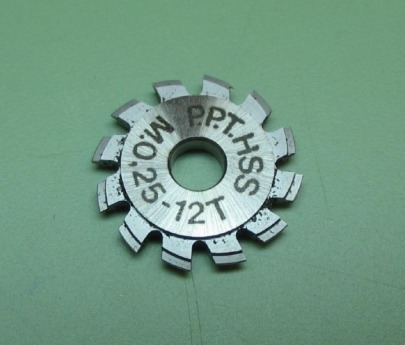
First, on page 120 (1st edition) under The Centre Pinion we can find the general guidelines for design of this pinion. Noting that it will receive the greatest load, directly from the barrels of 96 teeth, Daniels recommends that the center pinion have 12 leaves. Keeping the 0.25 module used to make the barrels, a 0.25M x 12 leaf pinion cutter was purchased from P.P. Thornton. Turning to the end of Chapter 6, Making Small Components, one can find the general description of the hollow center pinion and tapered key-setting arbor.
One can then proceed to the section in this chapter to read the instructions for Pinion Cutting and hardening and tempering. The center pinion being hollow and receiving a friction fit arbor, one then goes back to page 78 in the "Turning" chapter under the section Fitting a Double Roller to find instructions for fitting a tapered arbor. Finally, we then go to the section in "Turning" titled Turning and Fitting Pinions to find the instructions for the finishing of the pinion and fitting it to the center wheel. Daniel's book is interesting in this respect, when getting down to the nuts and bolts of what exactly I needed to do and determining dimensions, I quite often found myself needing to flip all over the book, sometimes in places you wouldn't think of at first, but just about everything you need to know is in there somewhere, and he saved a lot of paper by not repeating descriptions or drawings.
Pinion Specifications
No. of leaves: 12
Pitch circle: 3mm
Full diameter: 3.4025mm
Root diameter: 1.95mm
Leaf thickness: 0.3125mm
Addendum radius: 0.205mm
Addendum form: 1/3 ogive
Tooth/pitch ratio: 2/5
Addendum: 0.20125mm
Dedendum: 0.525mm
Full Tooth depth: 0.72625mm
Archie Perkins in his book "The Modern Watchmakers Lathe and How to Use It" describes the same basic setup as Daniels for making a center pinion. The use of a faceted male center for turning the arbor is used after forming the basic pinion blank.
A CAD drawing of the initial dimensions of the blank is below. Later as the pinion is finished a hand drawing was made to sketch out the final dimensions.
| center_pinion_-_cad.pdf |
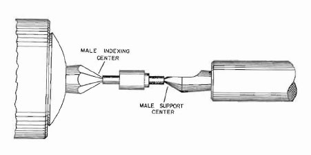
Scan from "The Modern Watchmakers Lathe and How to Use It" 2003- Archie Perkins
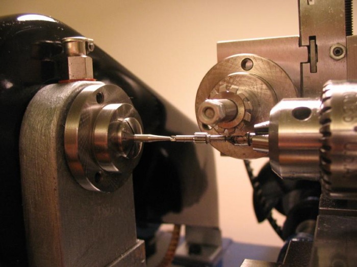
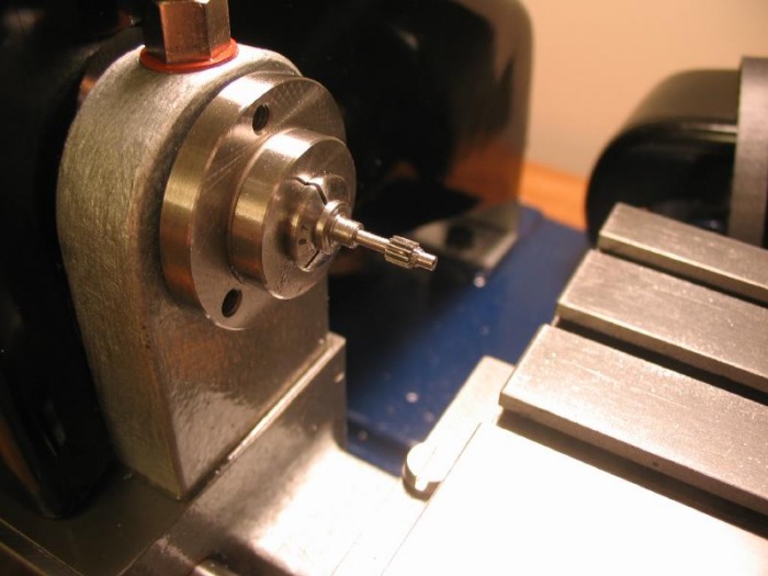
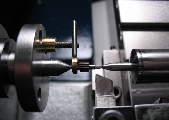
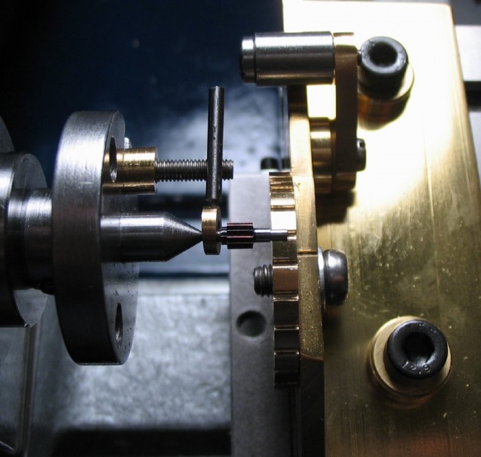
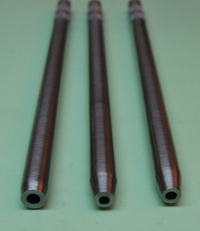
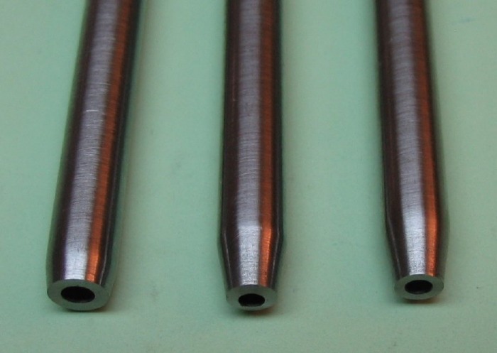
I was unable to make the faceted male center, none of the texts which describe it explain how to make one, I suppose I am missing something obvious here, it seems like a simple enough object, but the angled, concentric flats are not easy to produce. I tried to come up with an alternative and decided to use a jewelers 'bud' bur. It works with some success, at least the pinion looked okay afterwards, however I am sure this method introduced far more run out error than should be allowed. Here are some photos of the setup. I am running the mill on the slowest ratio, with the speed reduction wheel mounted on the spindle (300 rpm).
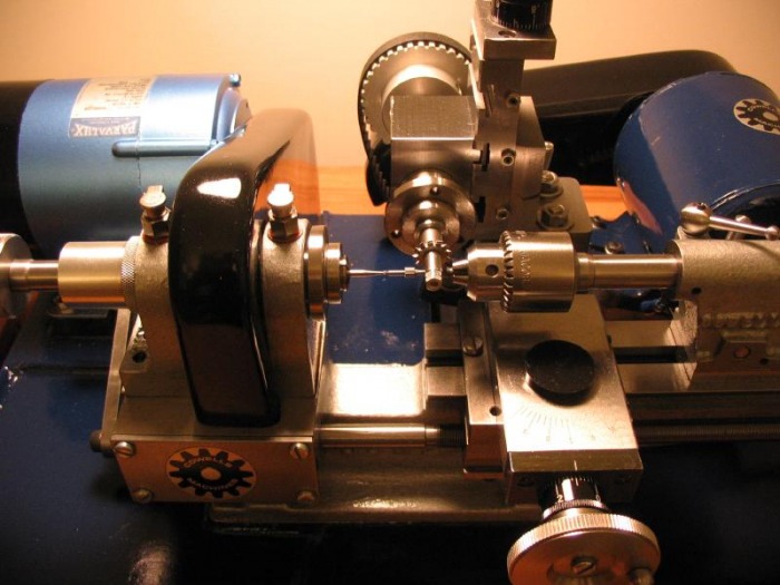

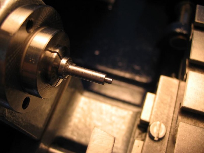
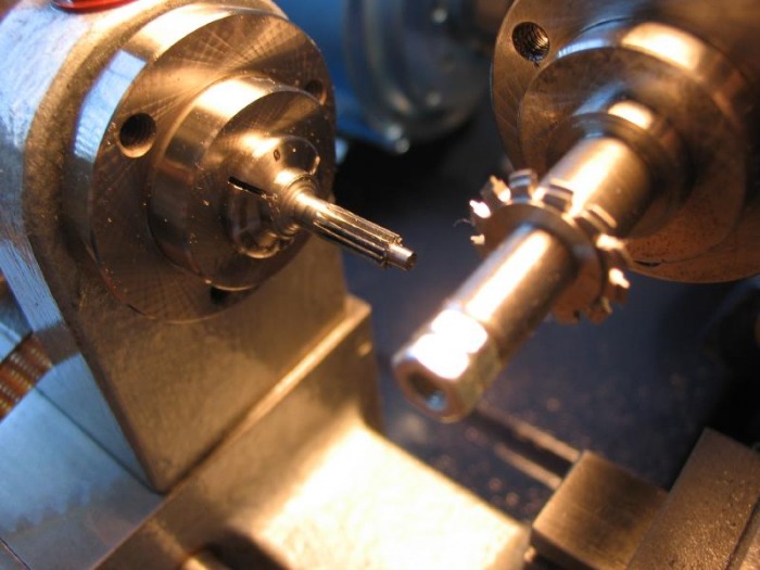
After some discussion on the NAWCC message board, it was suggested to me that I try making the pinion in its entirety in a single chucking from drill rod at least twice the pinion diameter, which should provide sufficient rigidity. So I used a section of 7mm drill rod and turned the basic dimensions, milled the pinion leaves and then center drilled and drilled to length using a carbide 0.65mm drill. The leaves at this module are quite fragile and it would be advisable to turn the complete dimensions, including wheel seat, etc. prior to milling the leaves.
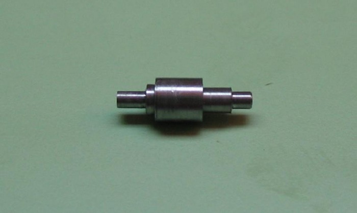
Dummy Pinion
| center_pinion_dimensions_-_hand_drawing.pdf |
Finishing
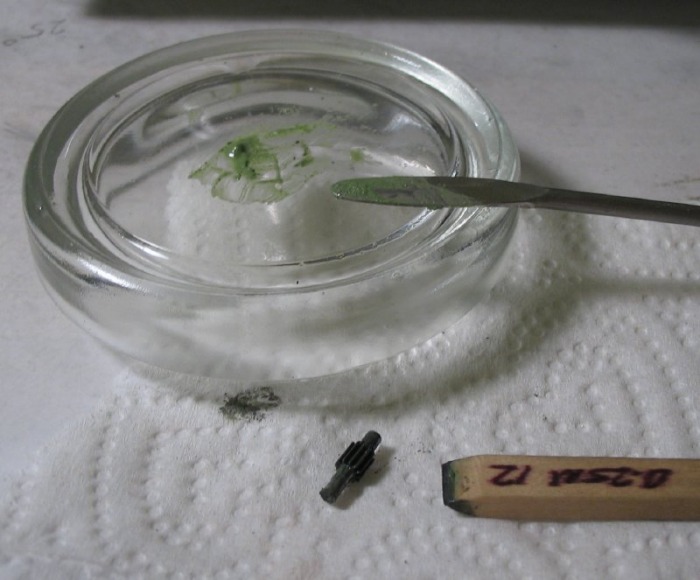
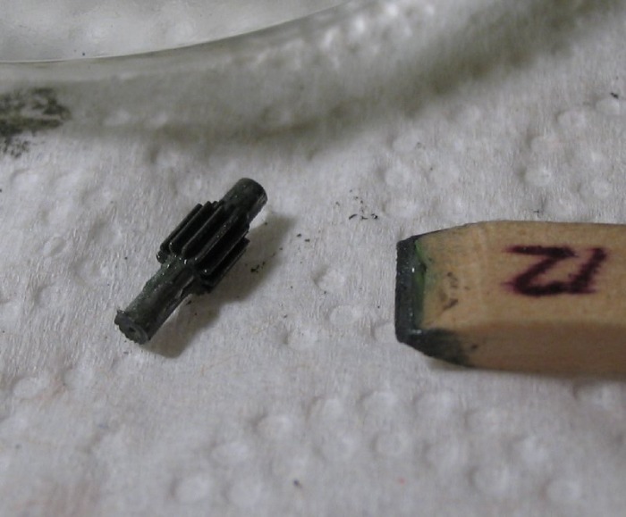
To begin, the previously made pinion must be hardened. It was loosely bound in iron wire (so loosely that it came undone during the photo...), and was heated in an alcohol lamp and quenched in oil.

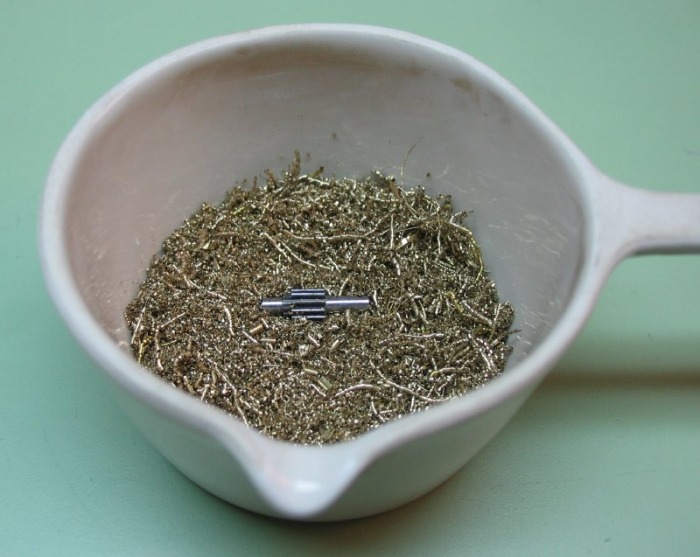
The blackened pinion was then polished with chromium oxide paste mixed with oil and applied with a piece of sharpened boxwood. The green paste is a medium polish between what I would consider oilstone and diamantine. This is to bring back a shiny surface only to be able to view the color changes during the tempering process to follow.
 Paste mixed with oil |
 Close up of the mess |

 |
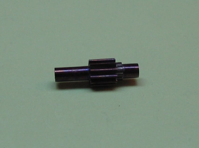 |
The pinion is now ready for its final turnings. I refer the reader to Daniels for the complete instructions, I summarize the process below.
The pinion is held in a collet by the leaves (gently) and trued by touching the face of the graver against the leaves. Once secured, the arbors are then turned true and to the shoulder diameter. To minimize the number of times it is removed and rechucked (to avoid accumulated error), the top portion was turned first and then the bottom and turning the wheel seat rivet. The rivet is undercut using a lozenge graver which I ground with a acute angle (~35 degrees). I found forming the rivet to be quite tricky, and this is confirmed in 'Watchmaking.'
The pinion was mounted between centers and the pivots turned using the dummy pinion as a guide for length. The pinion was supported on a Jacot drum and the pivots were smoothed with the pivot file and burnished.

The pinion could then be tested again for fit. The shoulder needed to be shortened just a tad for more endshake, which is a much better situation to be in than having too much endshake, since that can not be corrected. Afterward, the pinion can be shortened to be flush with the plates.
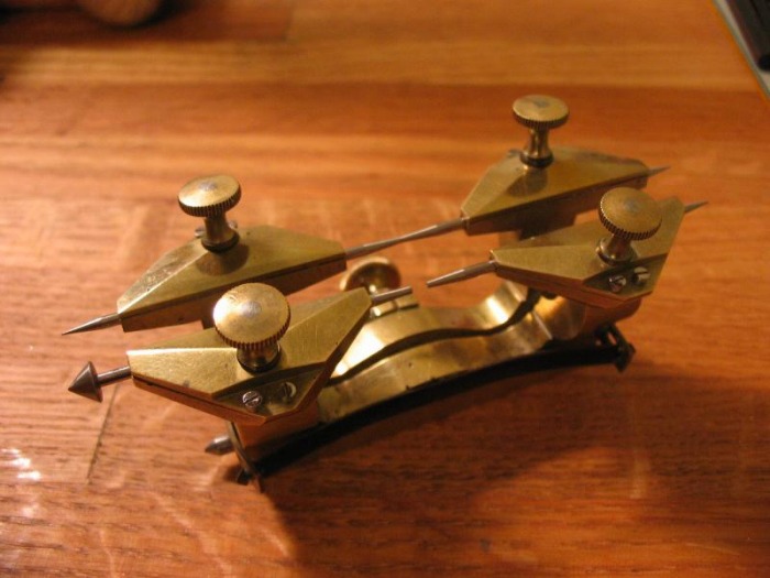
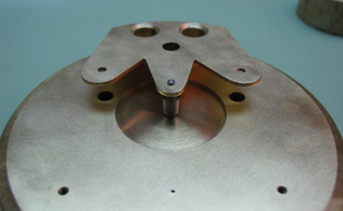
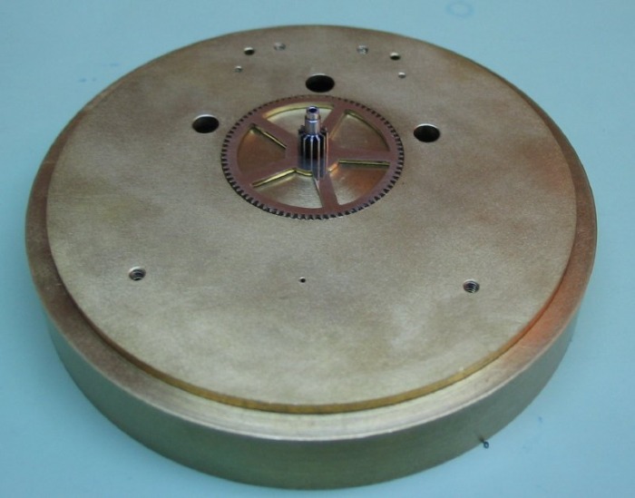
Staking Wheel & Pinion
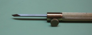
The punches from left to right 2.25mm hole flat punch, 1.75mm spreading punch, and 1.75mm hole flat punch.
 |
 |
The pinion is inserted rivet up into the anvil using the smallest hole that will clear the arbor, in this case 2.00mm. The flat punch above can then be used to tap the wheel onto the rivet.
 |
 |
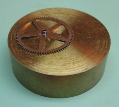
The spreading punch is used to open the rivet and the last flat punch is used to close the rivet and secure the wheel, as described above. I did not photograph these steps since it looks the same as above. The completed, staked wheel and pinion are shown below.
 |
 |
Testing the wheel in the plate, revealed that I was little strong handed with the hammer, and there was some distortion to the wheel. I then placed the wheel onto the brass barrel jigs to use them as a flattening anvil. A couple blows with a hammer and the distortion was corrected, however, in the future I will heed the warnings to use delicate hammer blows when staking a wheel.
 |
 |
Polishing the pinion faces
Polishers were made, following the technique described by Daniels and also by Archie Perkins. They are made from brass, about 25% larger in diameter than the pinion and a bore which is about 25% larger in diameter than the arbor portion. One of these, prior to parting off, was soft/silver soldered* to a small disc of zinc. The zinc is then drilled and turned flush, and the finished polisher parted off. The working surface is finished with a smooth file. The small notch turned on the end is for holding the polisher during use between fingernails.
* Various books refer to soft soldering or silver soldering, and I did not know what that meant. I am using a product branded StayBright silver/tin alloy solder (see specifications sheet below). It is supplied with its own bottle of flux, it melts at a low temperature (about 430 F / 220 C) easily done with a butane torch and no oxygen needed. It produces an excellent strong hold.
| staybright_solder_spec_sheet.pdf |