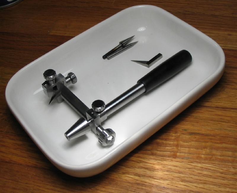
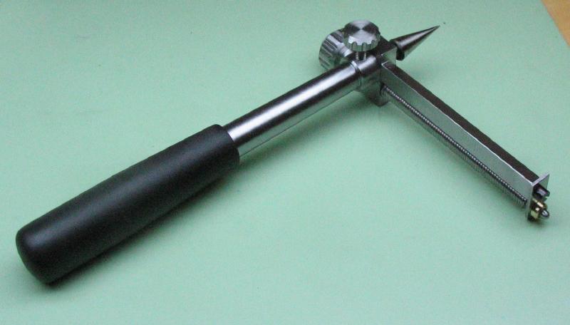
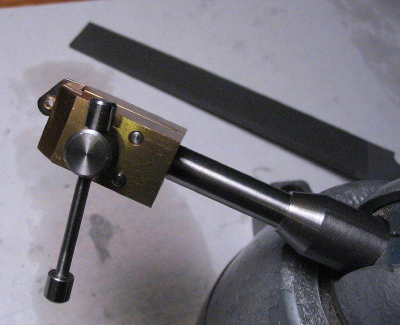
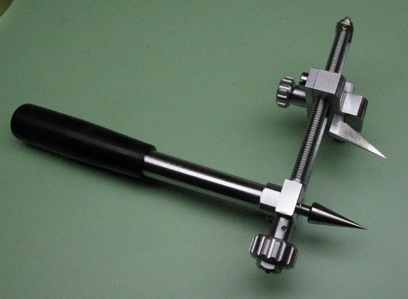
The tool described below may go by various names, but is simply a compass or divider intended for scribing arcs or circles from a central hole. It features a screw feed for setting the radius of the scribing point, which remains parallel to the center point regardless of radius. My design is based on a line drawing in Daniels "Watchmaking" and photos of similar looking tools that can be found around the internet. Bergeon offered a version of this tool (No. 6472), but appears to be long discontinued.
Since I may not get around to creating a proper drawing, a scan of the sketch used at the workbench is attached below. Keep in mind that many of the dimensions and various details in the drawing do not match what was ultimately decided on.
| Compass Sketch |
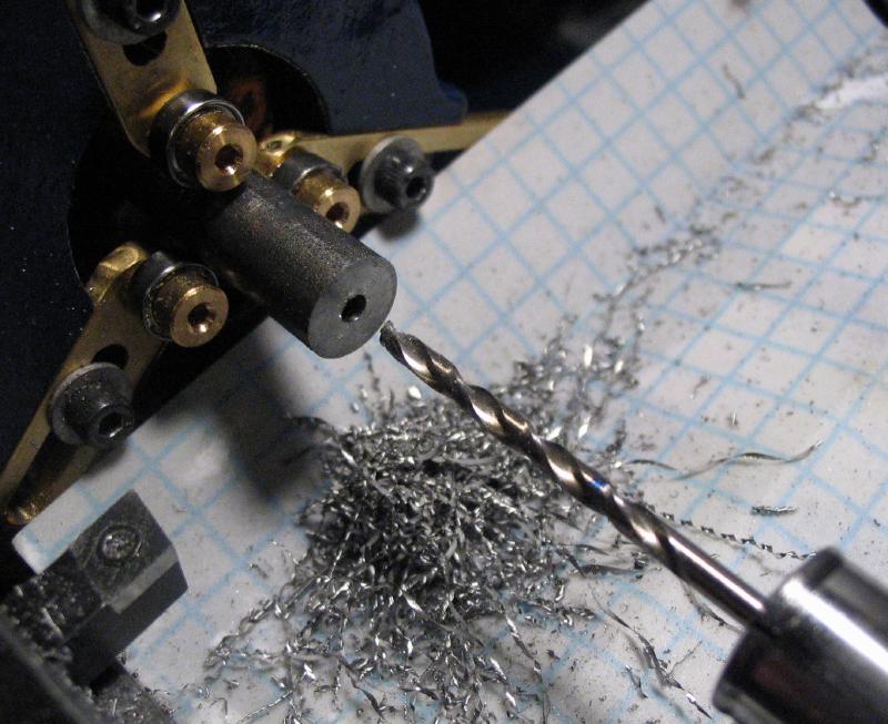
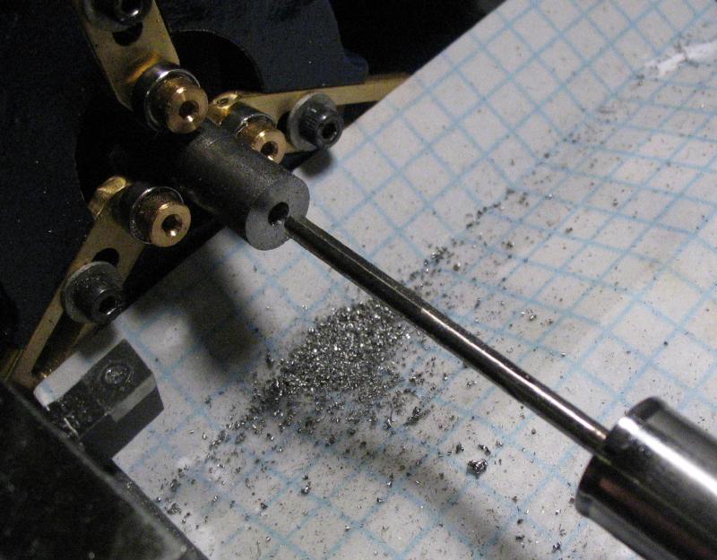
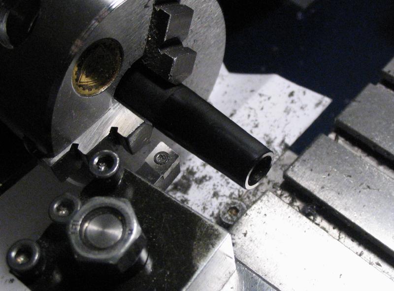
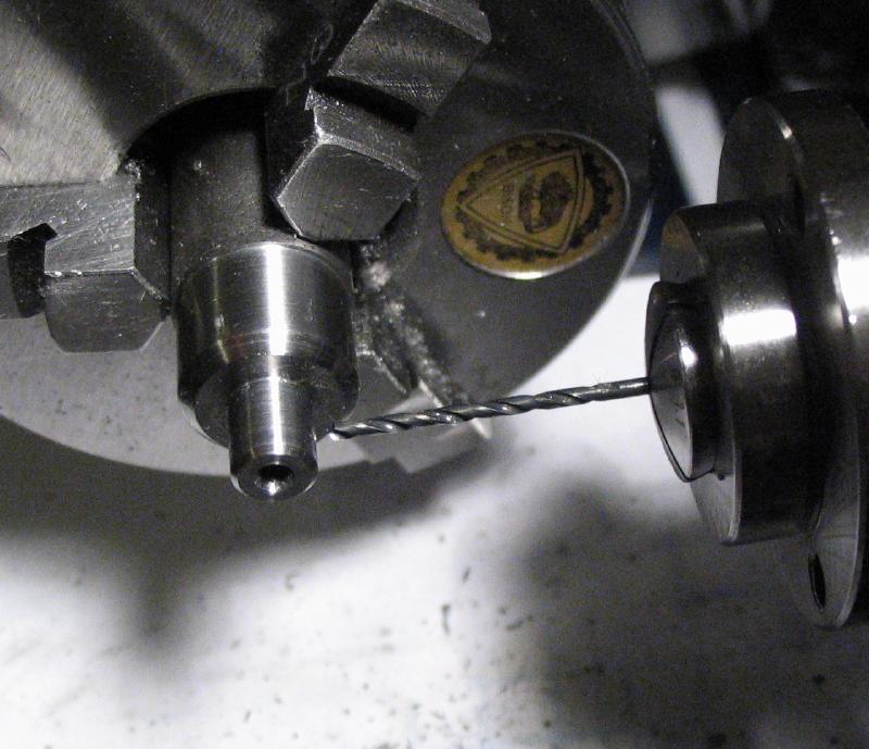
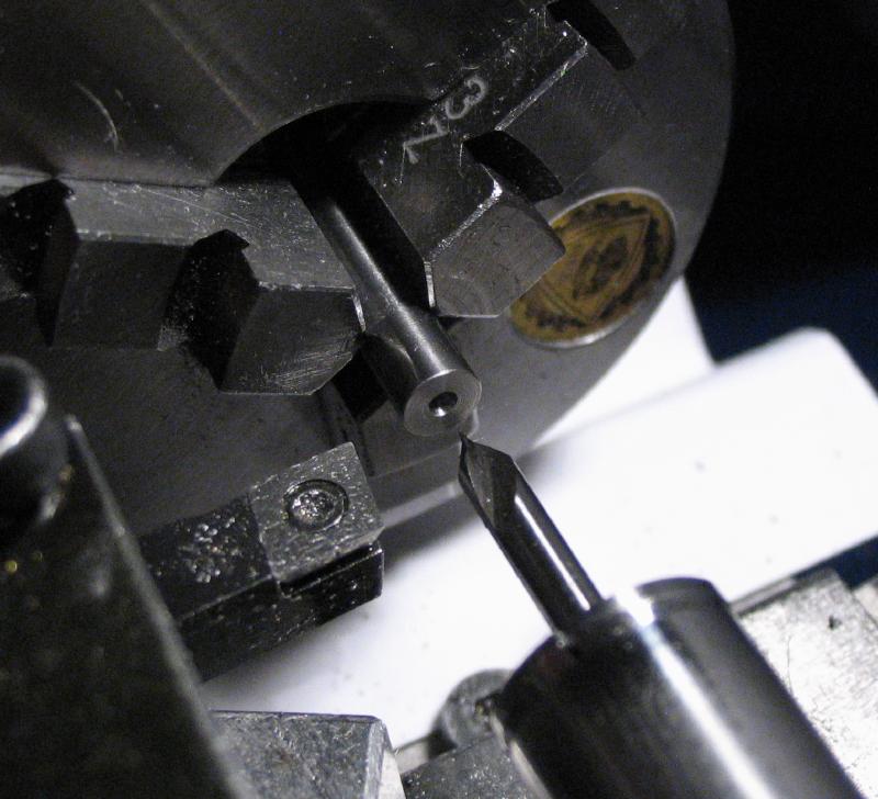
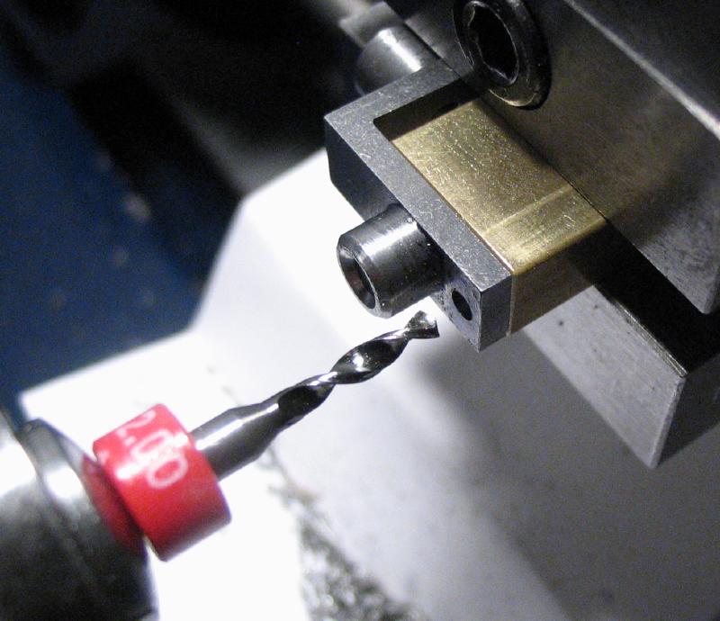
I started with the easier components, beginning with the central shaft of the tool, which will attach to a handle on one end and hold the center cone point on the other. It will also attach to the remainder of the tool, primarily the guide bar assembly. A length a little over 2 inches of 3/8" diameter 12L14 cold roll steel rod was faced on either end using the steady-rest for support, and then one face spot drilled, drilled 2.5mm for about 20mm in length, and then reamed open to 3mm (a slightly larger drill would be preferred, say 2.7 or 2.8mm, but 2.5mm was the closest I had on hand in the required length).
|
|
|
|
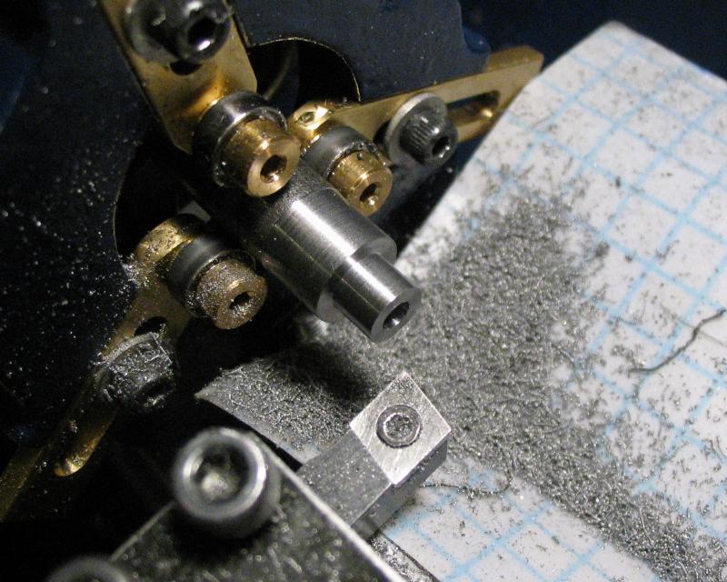
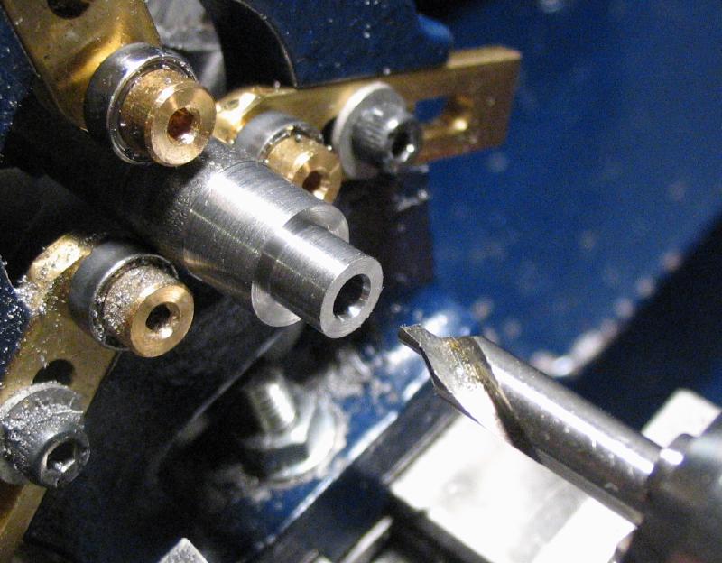
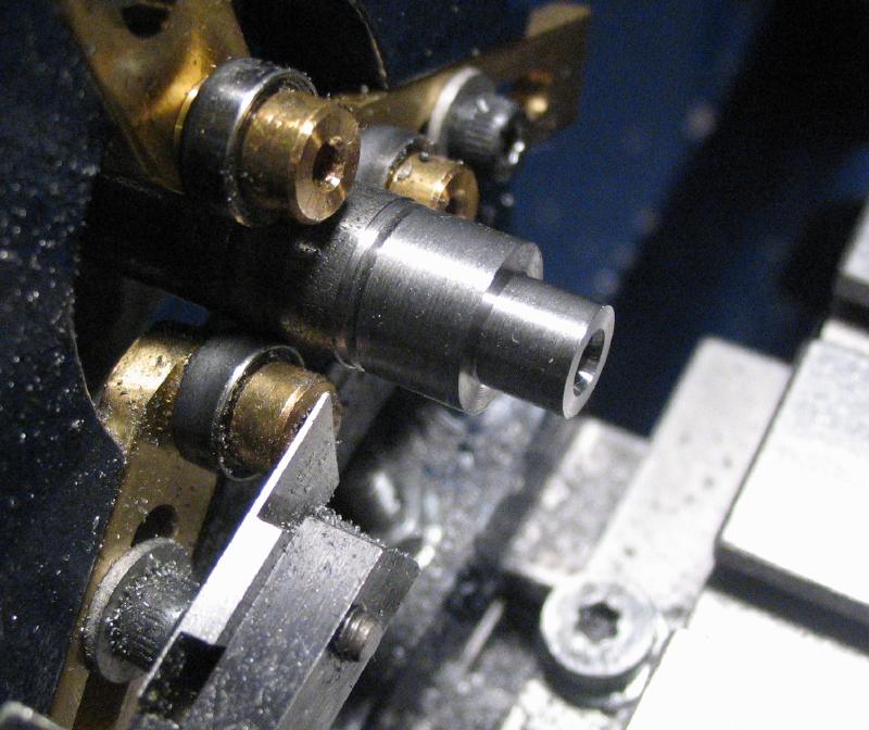
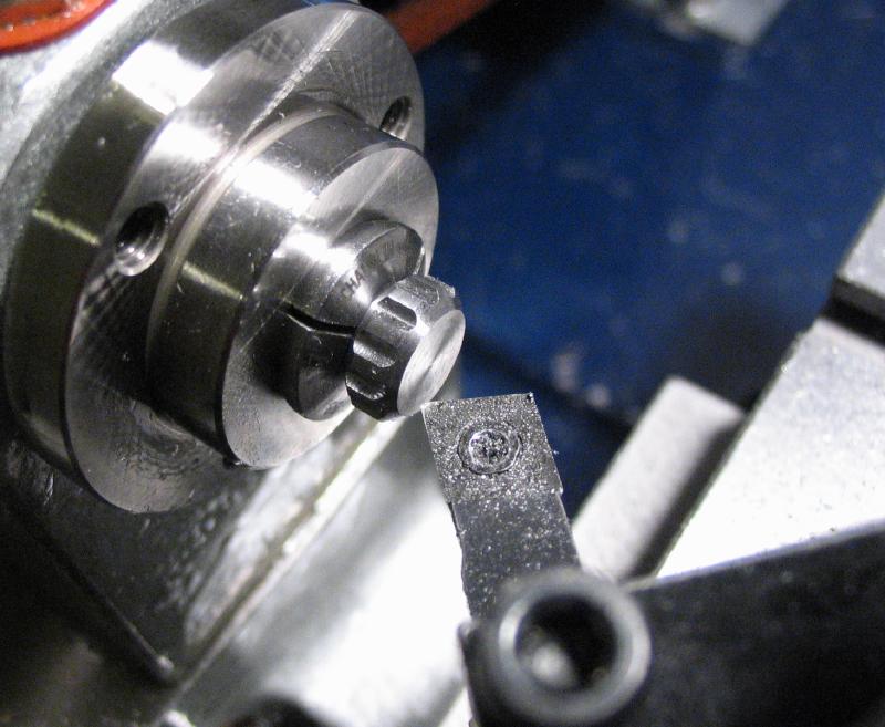
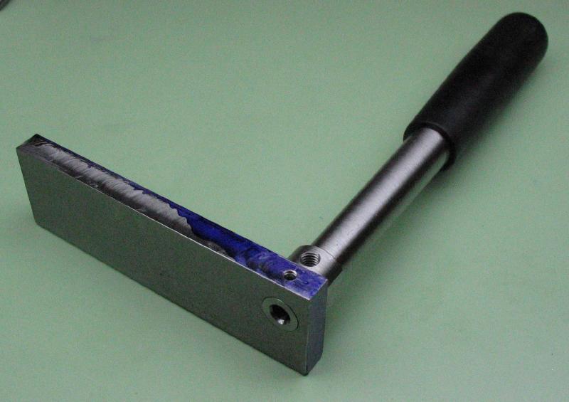
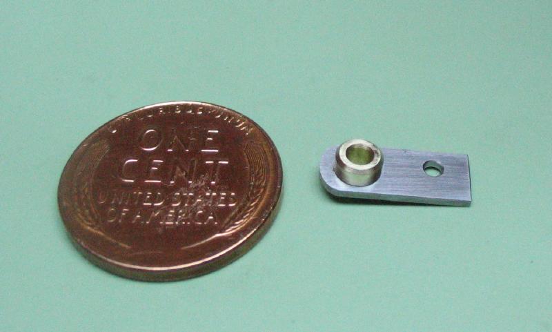
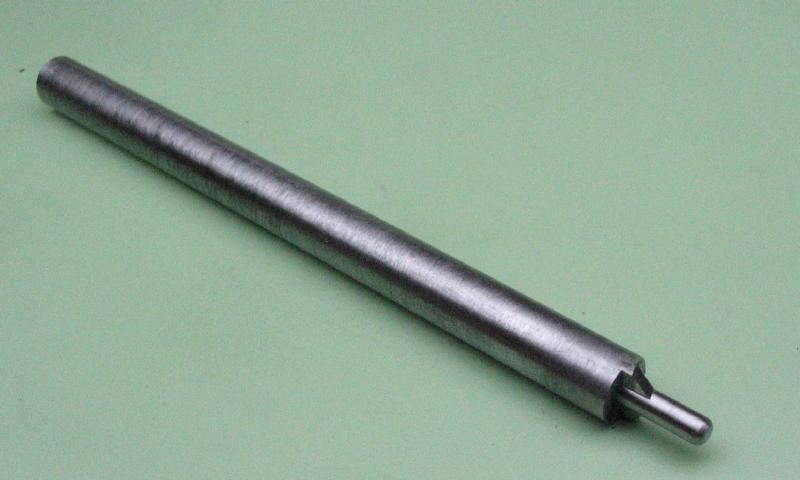
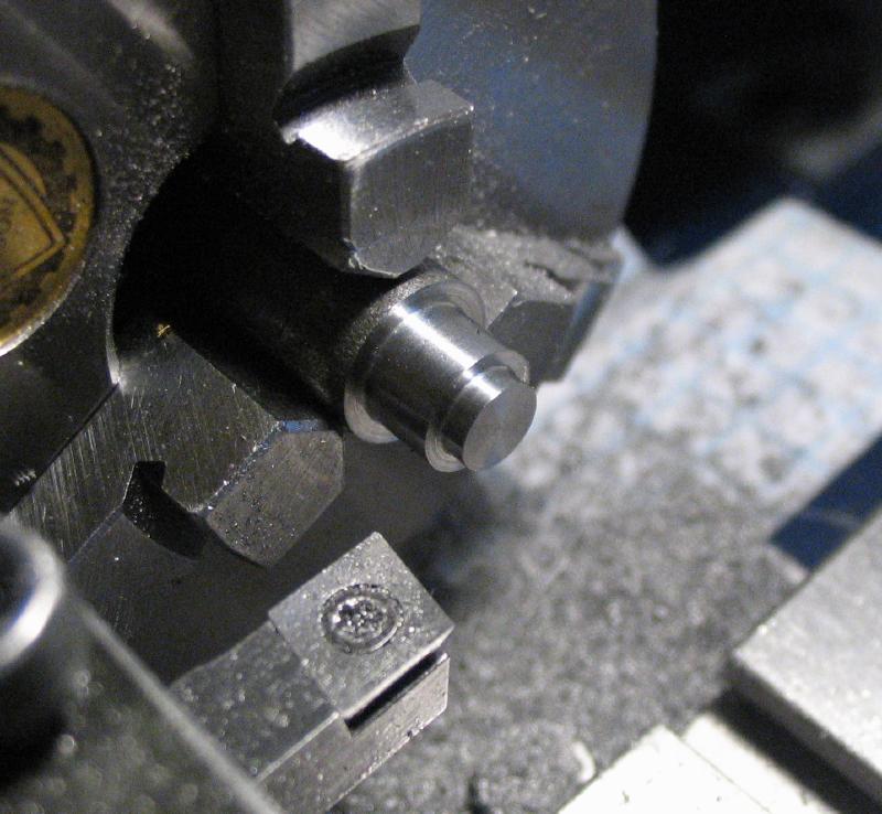
The end of the rod was turned true and left at about 9.2mm for about a half inch length (I originally planned on 9mm diameter, but was redesigned on the fly and could be left larger). The end was turned down to 6mm for 4.8mm in length (slightly longer than 3/16"). The hole was countersunk 60 degrees with a countersink drill for tailstock support in the next steps, and a parting tool was used to rough out the flange portion.
|
|
|
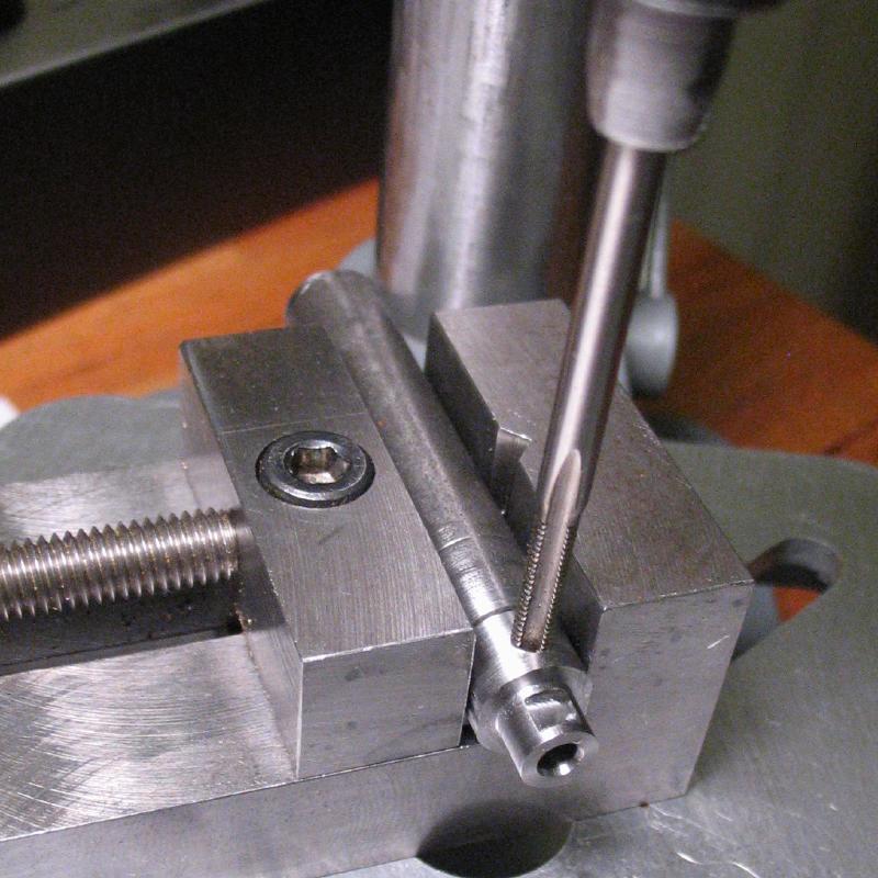
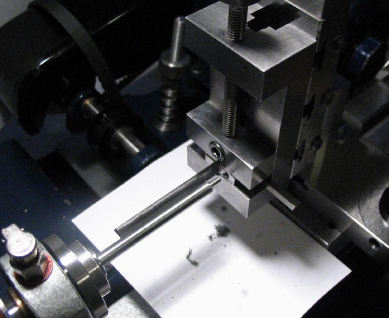
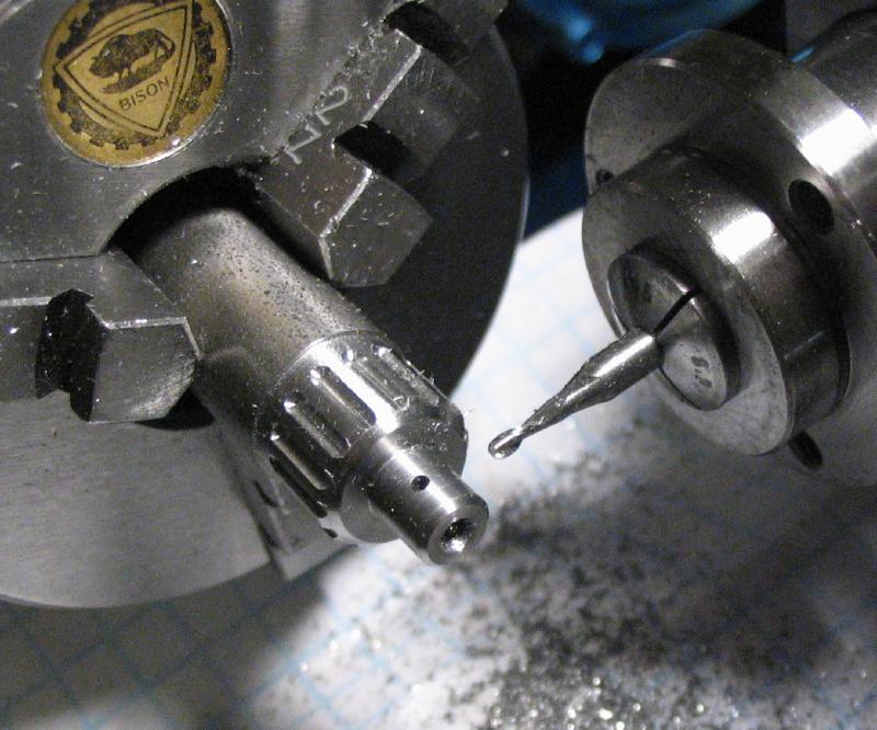
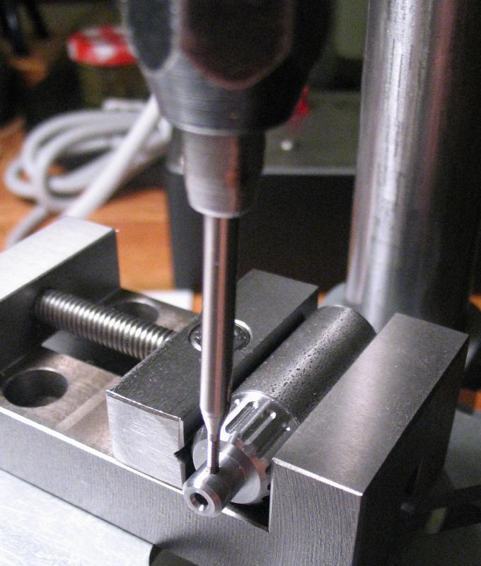
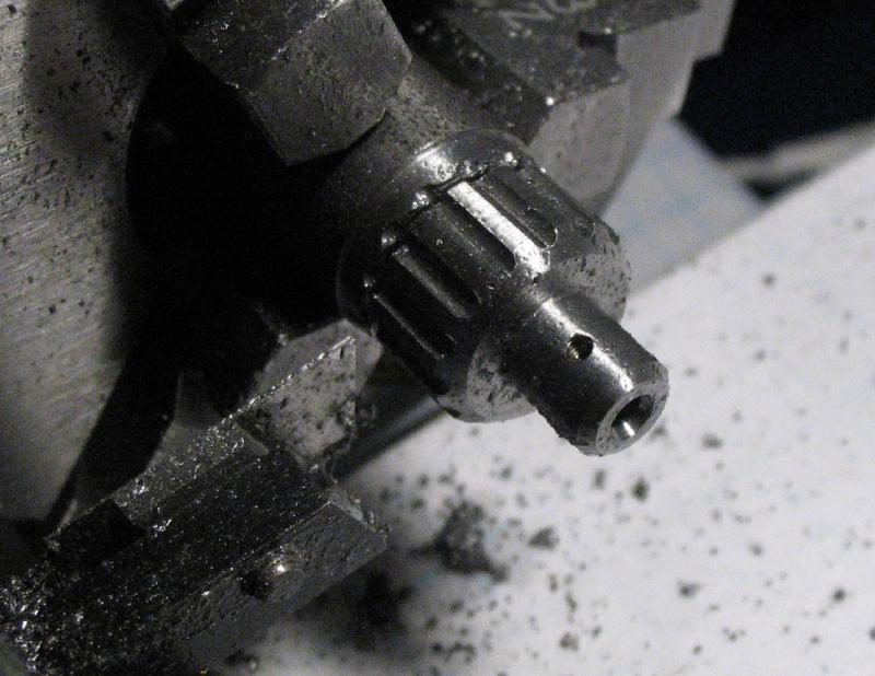
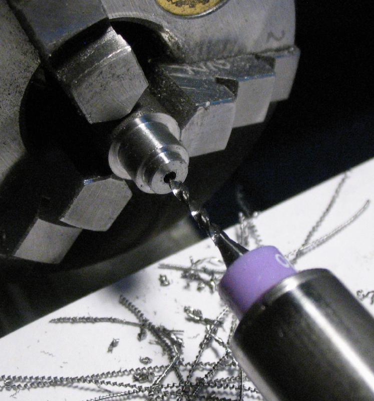
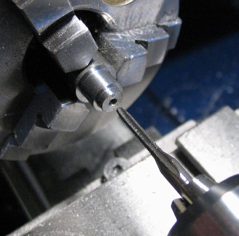
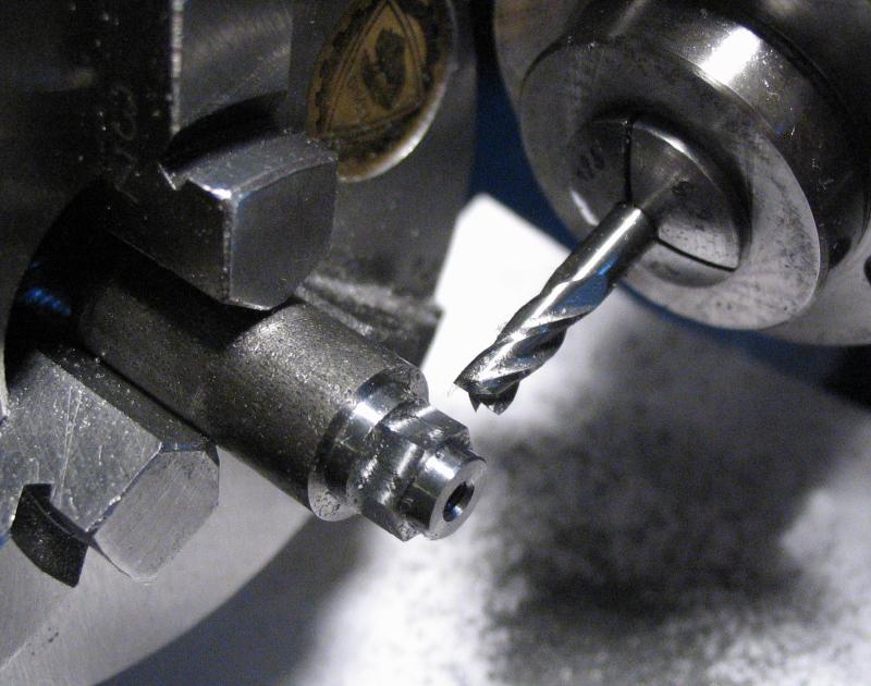
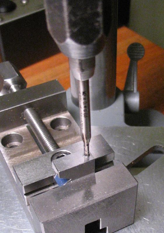
The milling spindle with a 1/8" endmill was installed and with the headstock locked, a flat was milled into the 6mm diameter end for a set screw. The spindle was put onto center height and the flange drilled 2.5mm, and flats milled on the other 3 faces opposite to the drilled hole. The work was moved to the drill press to use as a set up for tapping the hole M3x0.5mm.
|
|
|
|
|
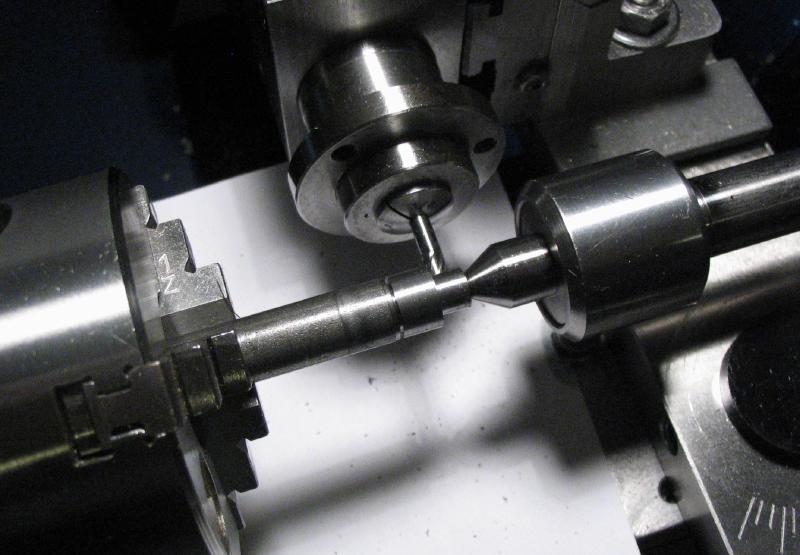
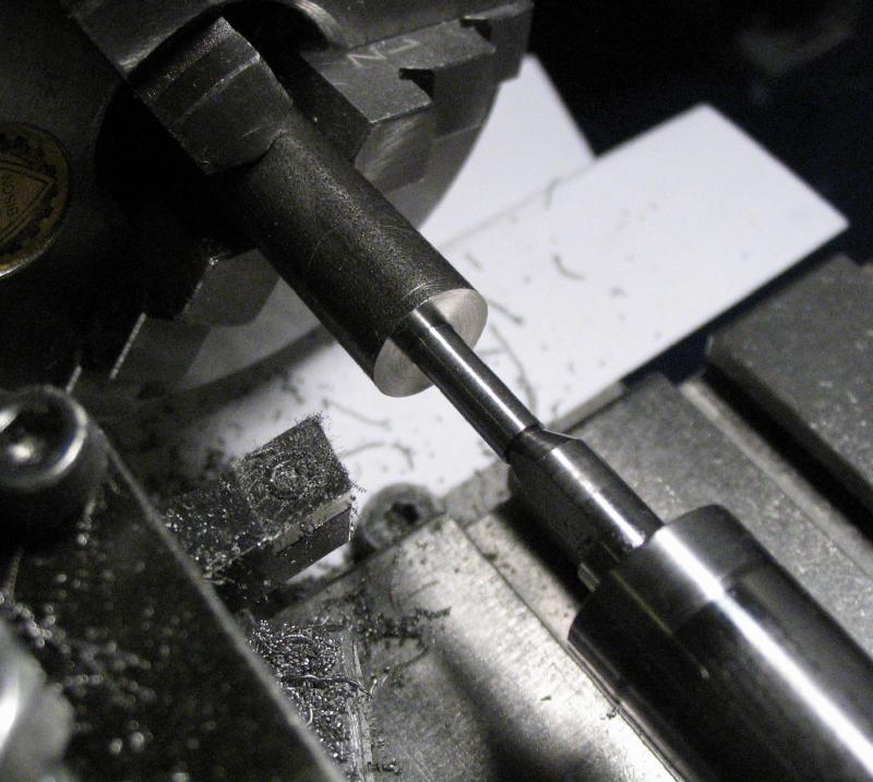
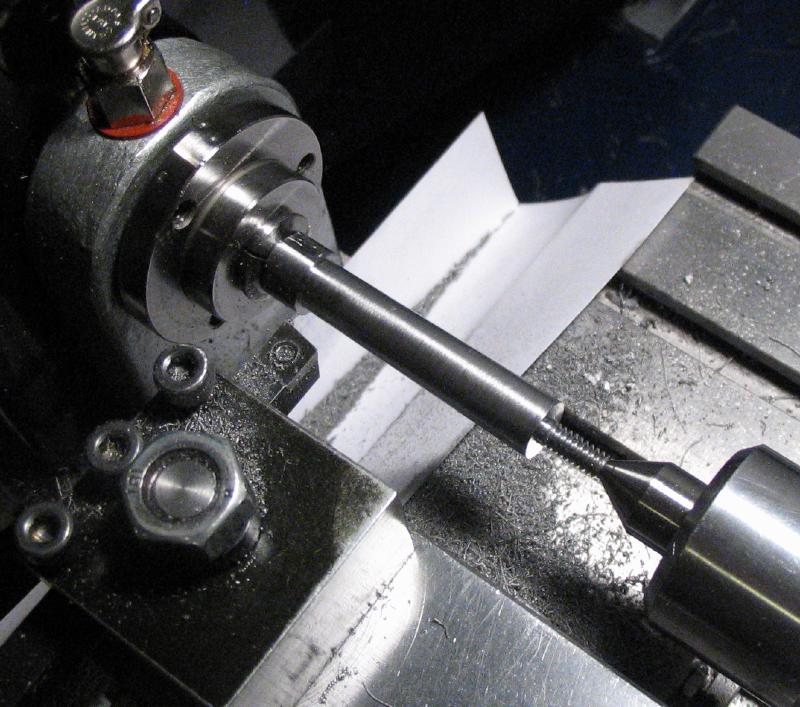
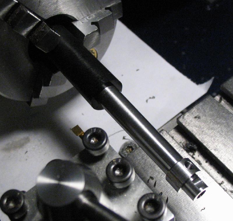
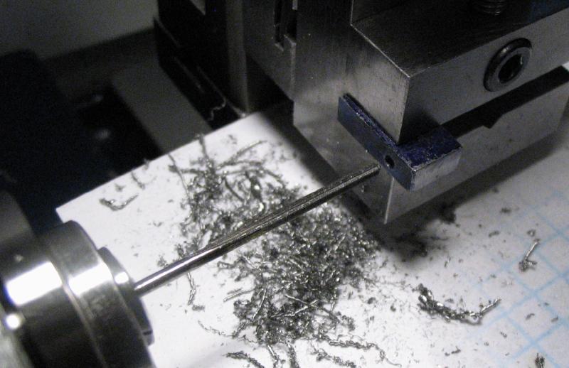
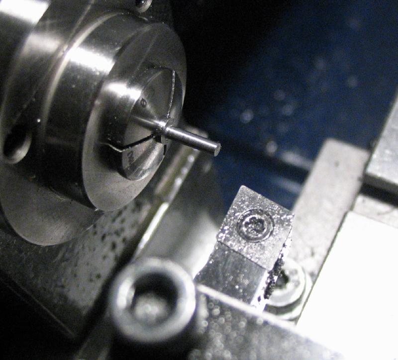
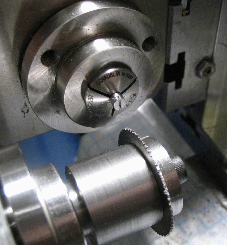
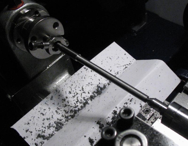
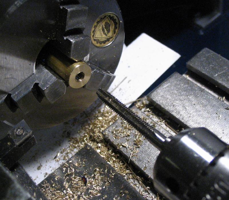
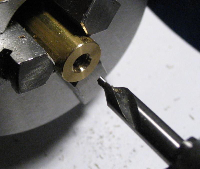
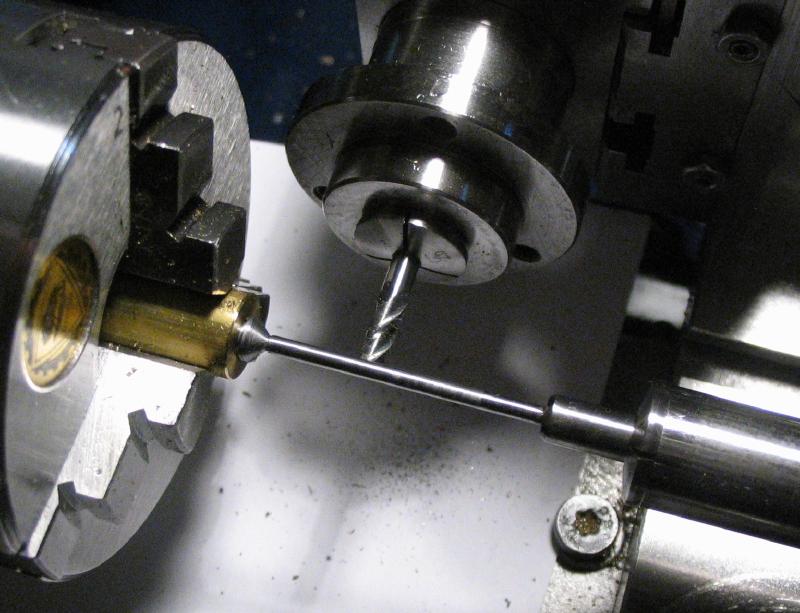
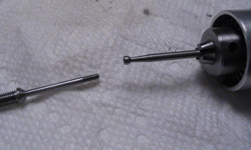
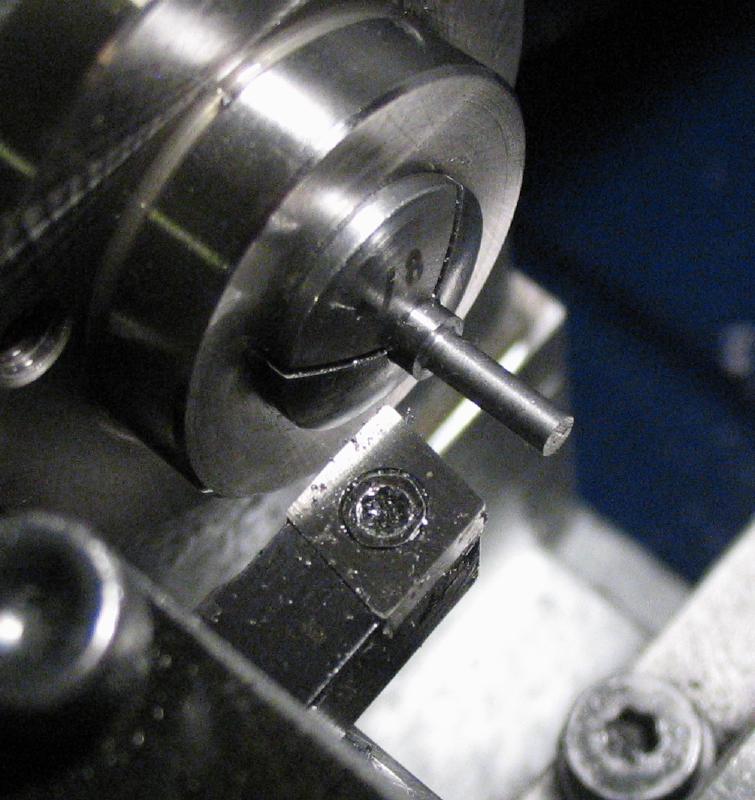
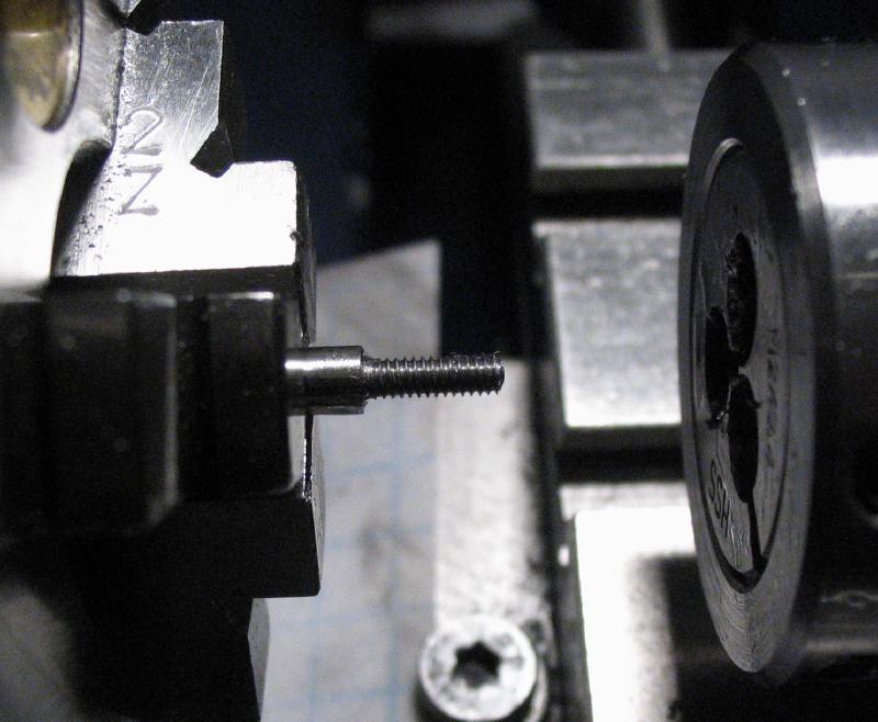
The work was reversed back into the 3-jaw chuck and center drilled for tailstock support. The end was turned down to 3.5mm and threaded #6-32. I used this thread size as a compromise between choosing M3 or M4. The work was transferred to a 6mm collet and the compound slide set to about 1 degree and used to turn a taper that has extreme diameters of about 7 and 8mm and is about 32mm in length with a short length left at 8mm, which will fit into the handle.
|
|
|
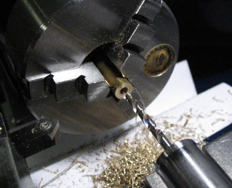
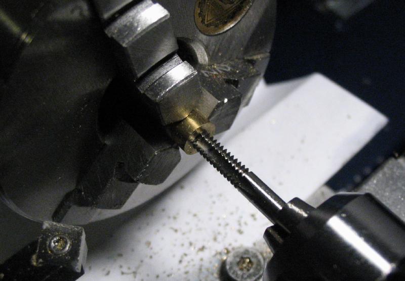
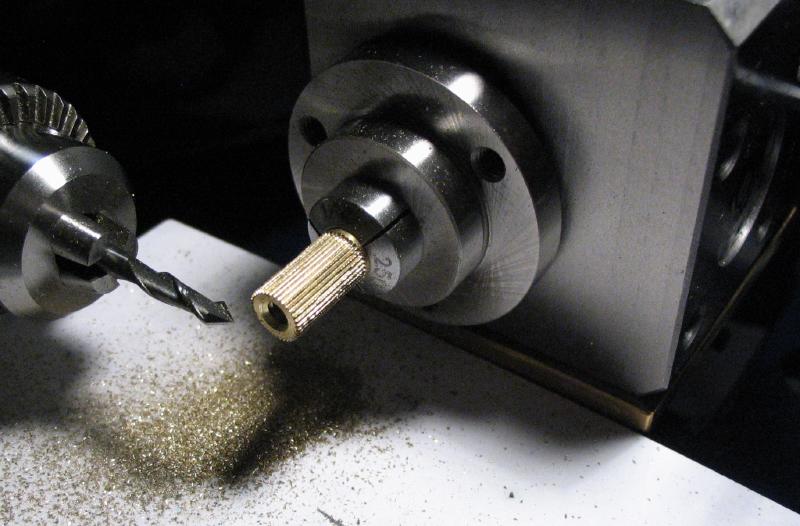
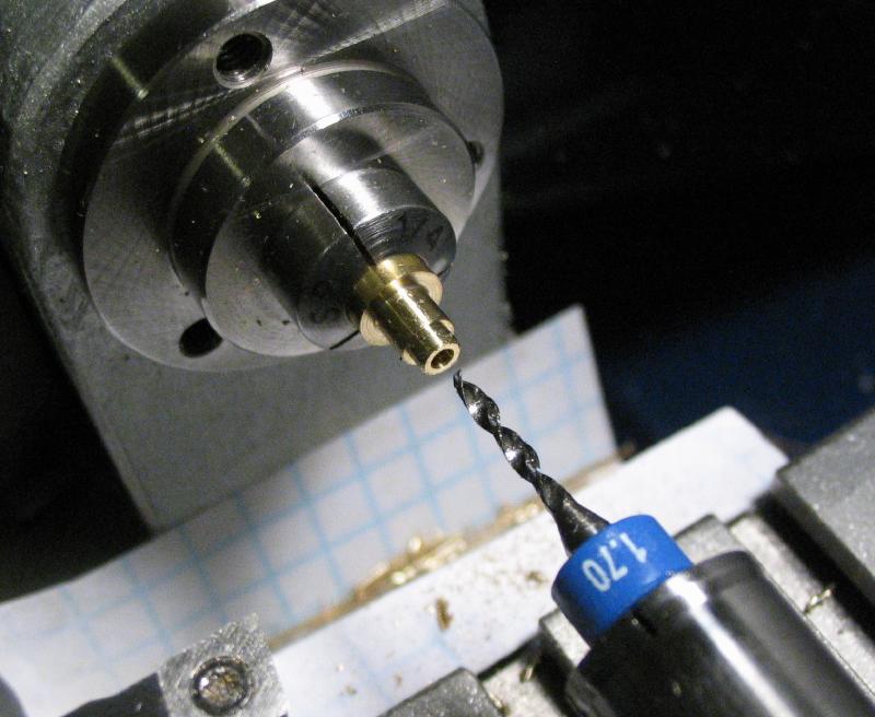
A threaded insert for the handle was made from a short length of 1/4" brass rod. It was drilled #36 and tapped #6-32, and then moved to the dividing head for milling 36 splines with a 60 degree mill-drill. These mill-drill bits are not intended for cutting a groove (can be used for just about anything other than that), but these are fairly shallow grooves, and the quality of the groove is not critical as they need only grip the inside the handle. The end was chamfered and the insert finally parted off at about 10mm in length.
|
|
|
|
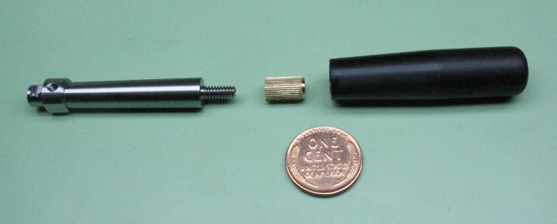
I originally planned on a wood handle, but changed my mind to black polyoxymethylene (POM), usually known by the brand name Delrin, but this piece has a different manufacturer. It machines well and could likely be drilled and threaded to fit the shaft, but instead it was simply drilled to fit the brass insert already made. I started with a 2 inch length of 1/2" diameter rod, and rounded the end with a graver and smoothed with a file. The exposed portion of the rod (about half the length) was smoothed with emery paper and the rod then reversed in the chuck. The other end was faced, and drilled 6mm to a depth of about 14mm. The hole was counterbored to a depth of 1.5mm and to fit the full diameter of the shaft (8mm). The shaft piece can be tried in the bore between the final passes of the boring bar to find a good fit.
|
|
|
|
The handle was turned with a taper of about 3 degrees, and finished with emery paper.
|
|
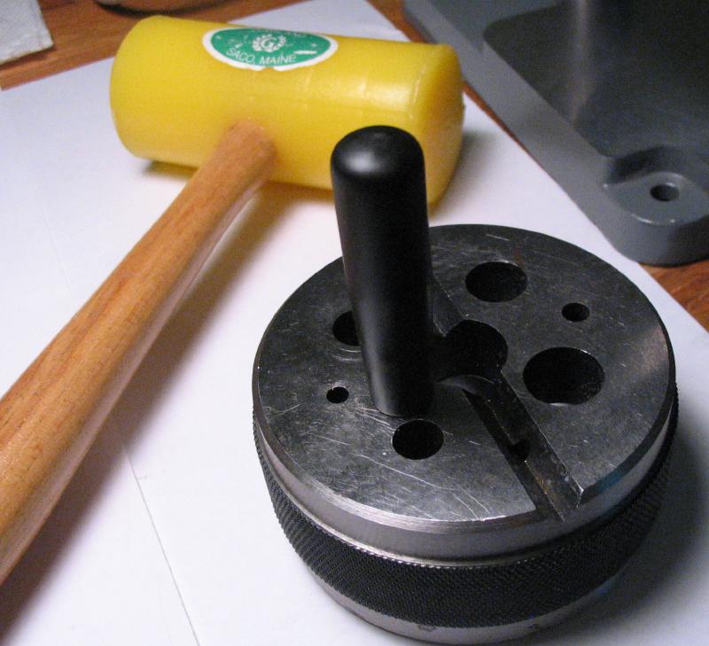
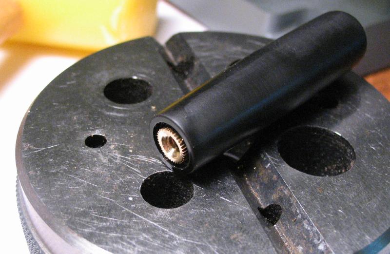
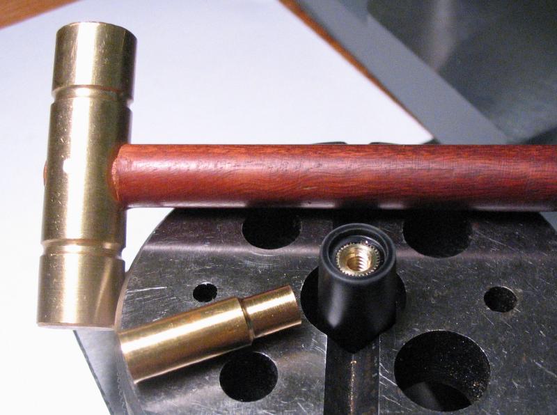
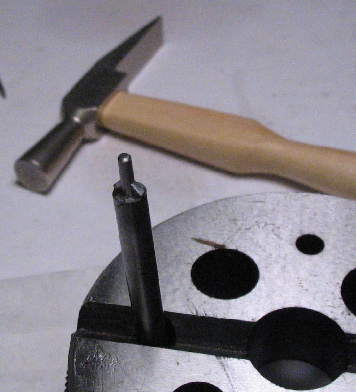
The handle was driven onto the threaded insert with a mallet and the bench anvil and a short length of brass rod was used to drive the insert flush with the counterbore.
|
|
|
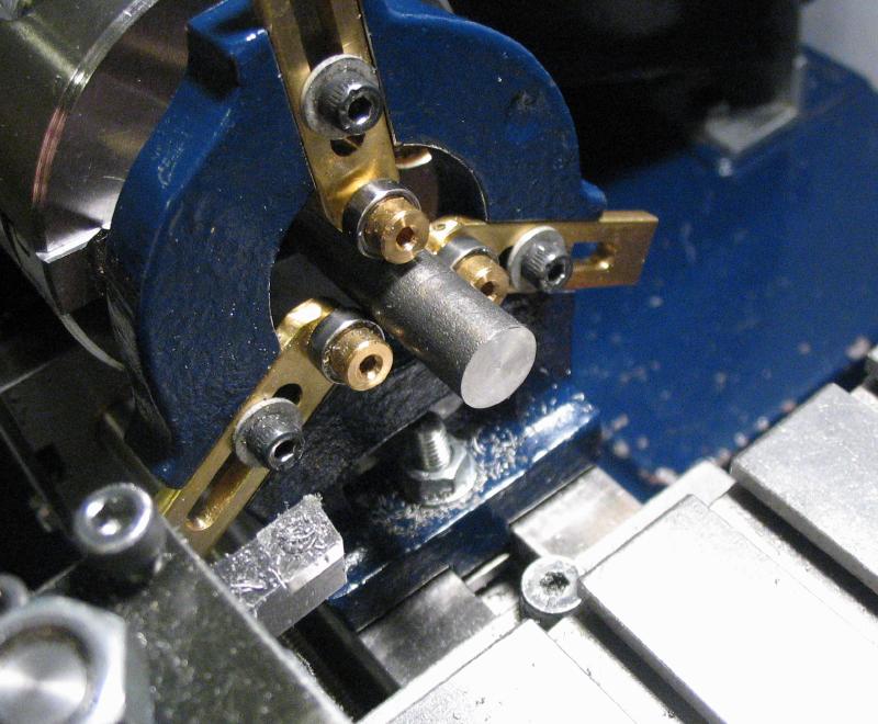
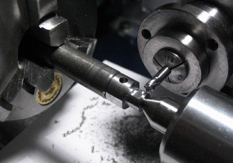
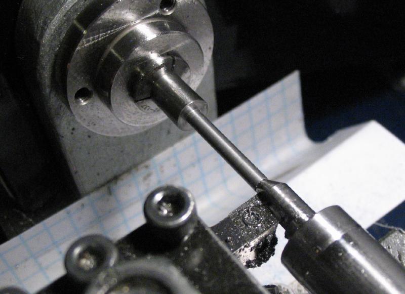
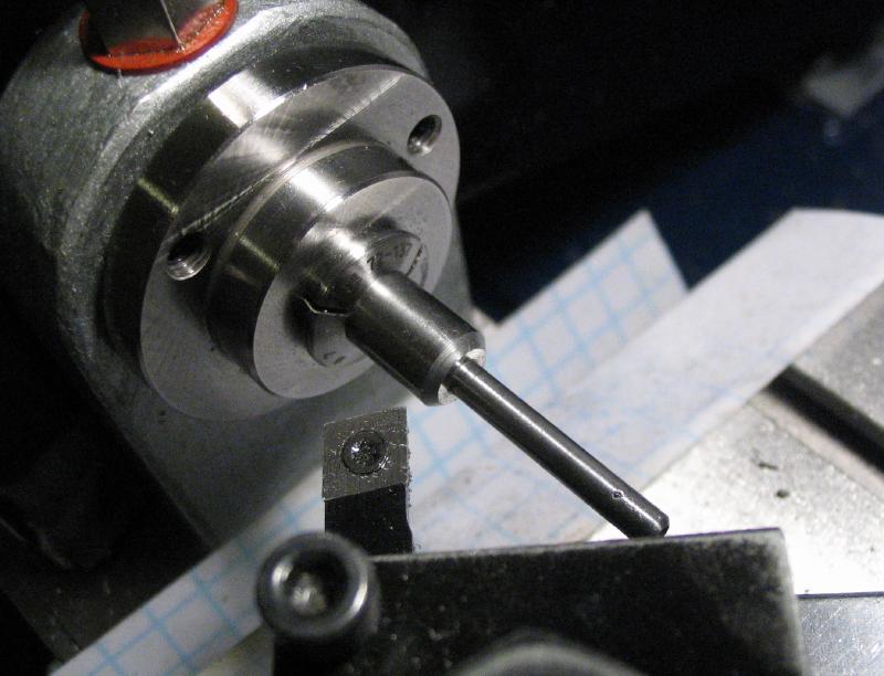
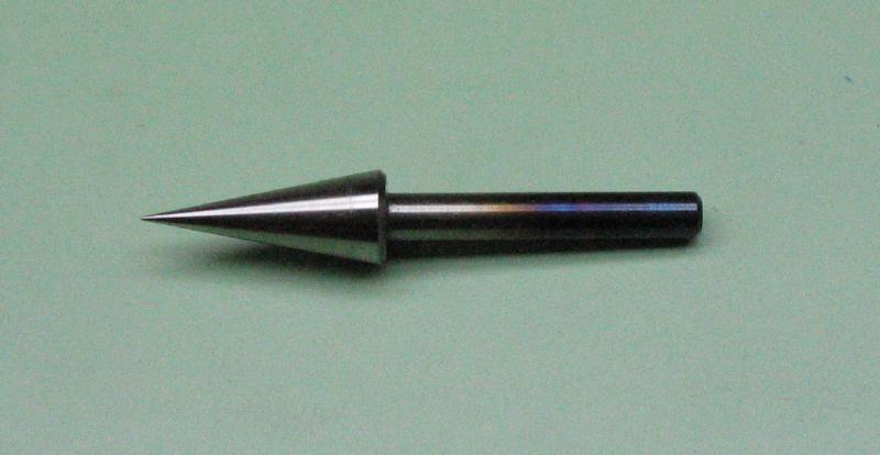
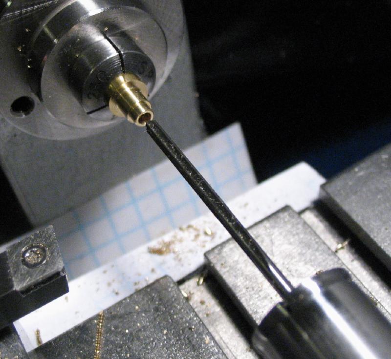
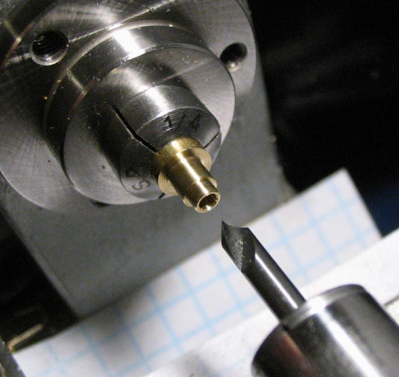
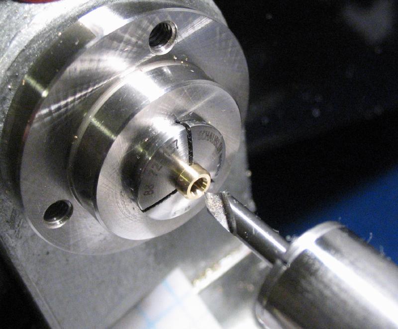
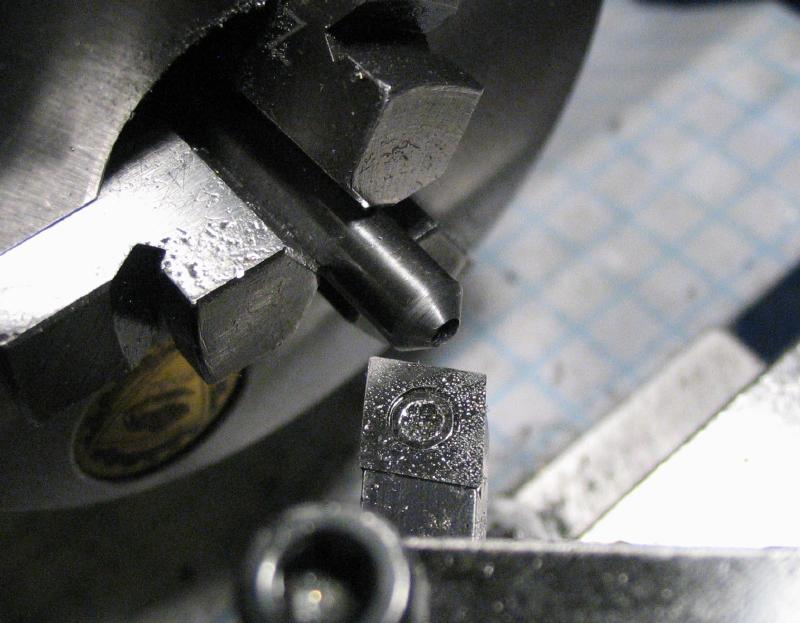
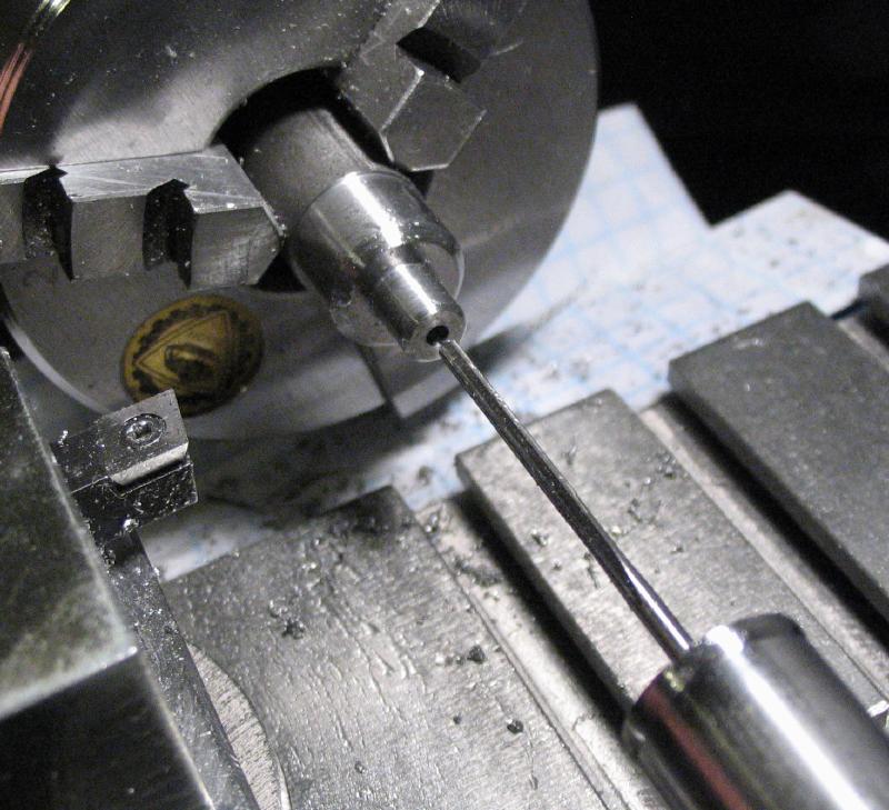
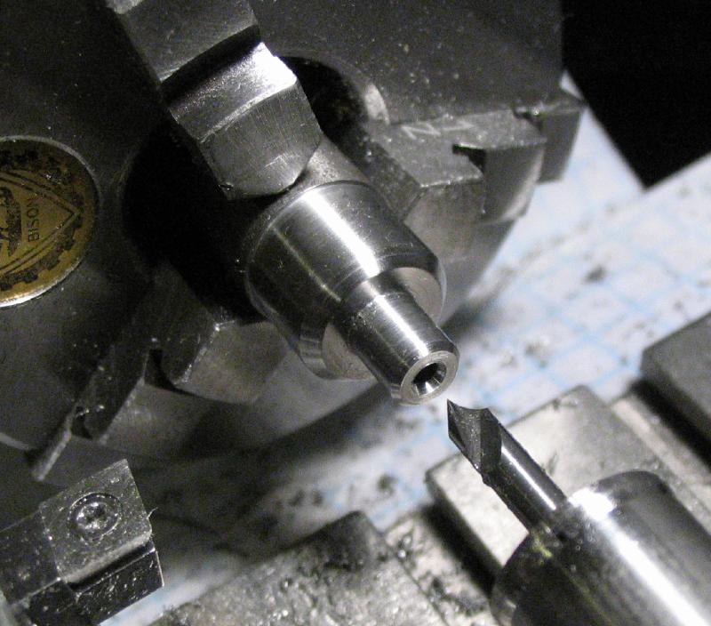
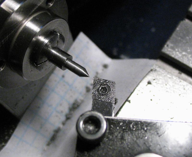
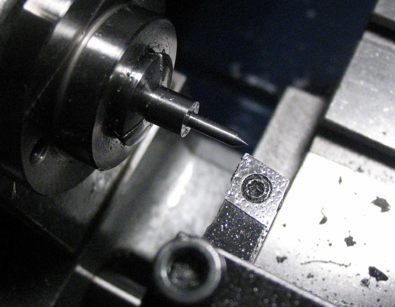
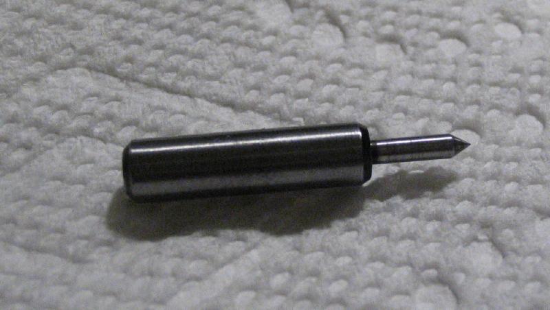
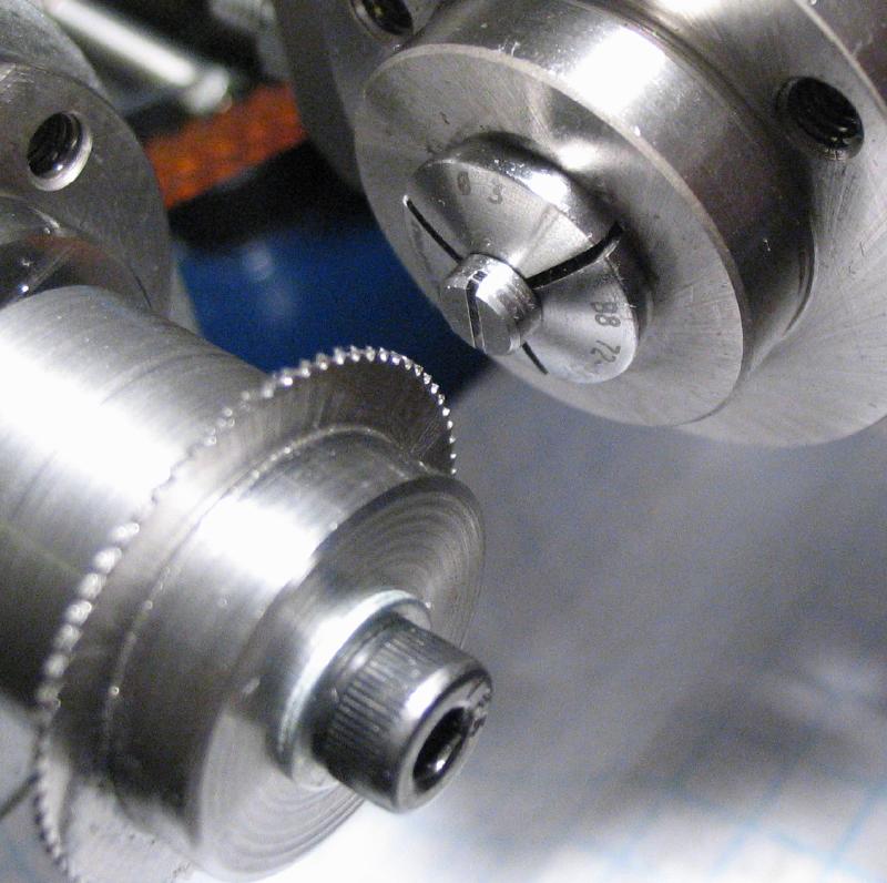
A cone center was made from oil hardening drill rod. It was first faced and center drilled for tailstock support using the 3-jaw chuck. It was moved to a collet and a length of 20mm was turned down to 3mm. It was then reversed into a 3mm collet and a 10 degree taper turned to form a long cone point. I initially started with 7mm drill rod, but planned on a 15 degree taper, so needed to sacrifice some diameter to accommodate the change. The full diameter of the cone ended up as 6mm.
|
|
|
|
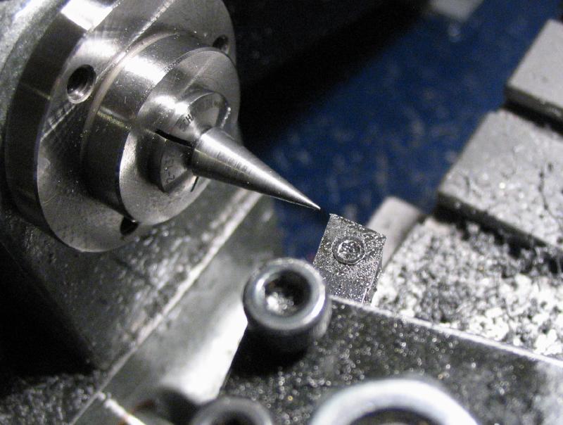
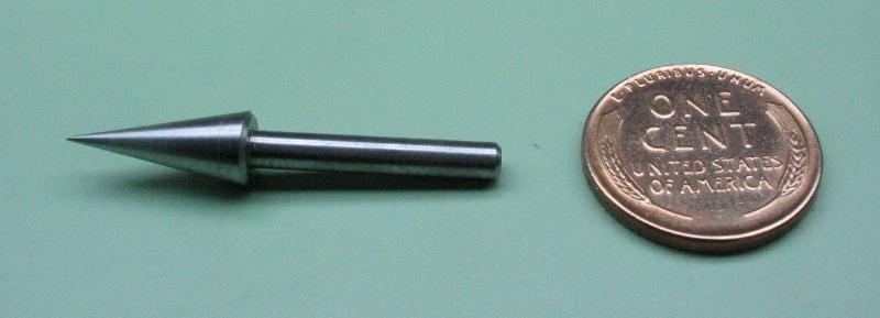
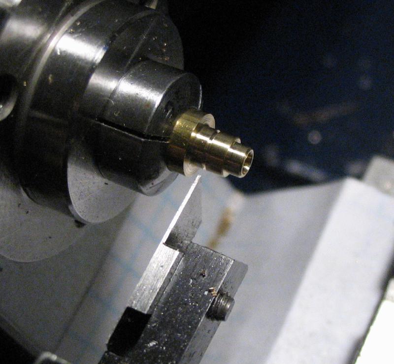
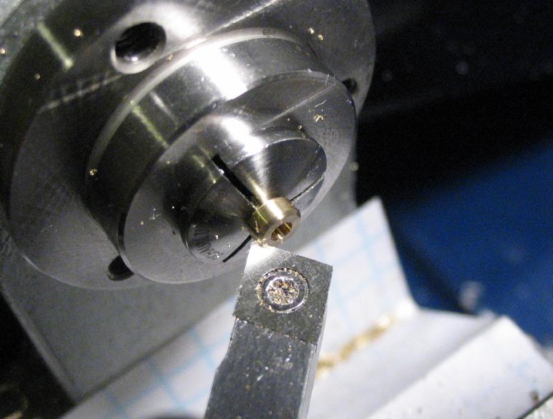
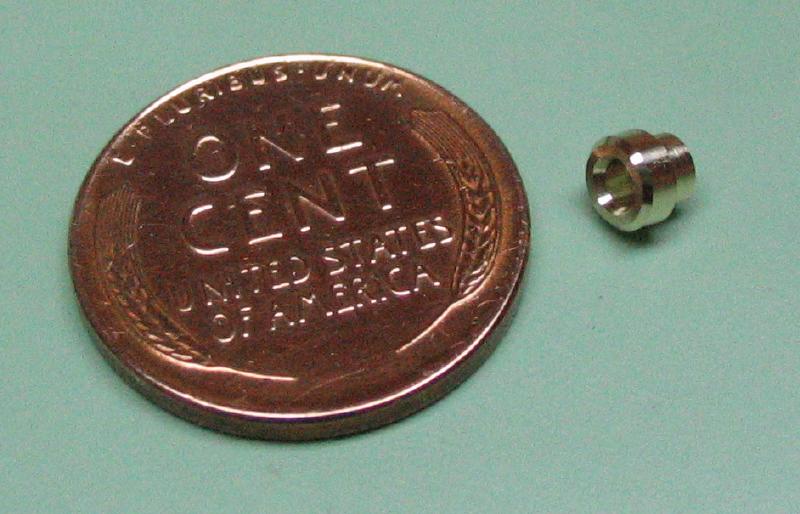
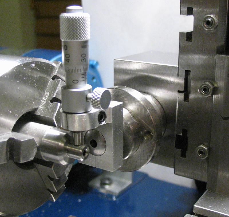
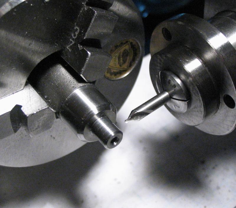
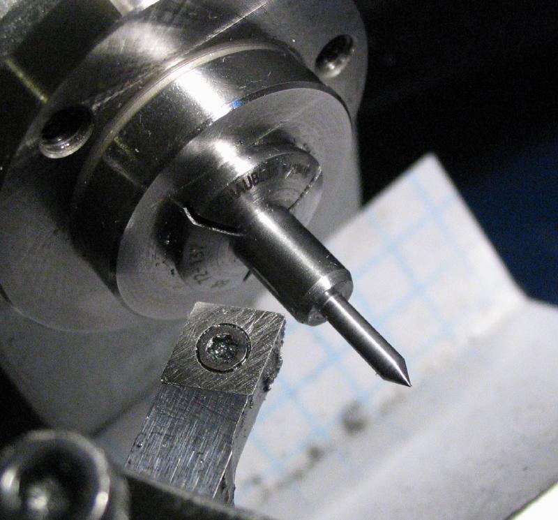
The center was polished with an India stone slip and then hardened in oil. It was inserted into a piece of brass rod that had been drilled for short length to fit the 3mm shank of the center. The brass was heated with an alcohol lamp and stopped when the the tip of the center began to change color to straw. This should leave the cone portion fairly hard and the temper of the shank will range from straw to blue, but this should not matter.
|
|
|
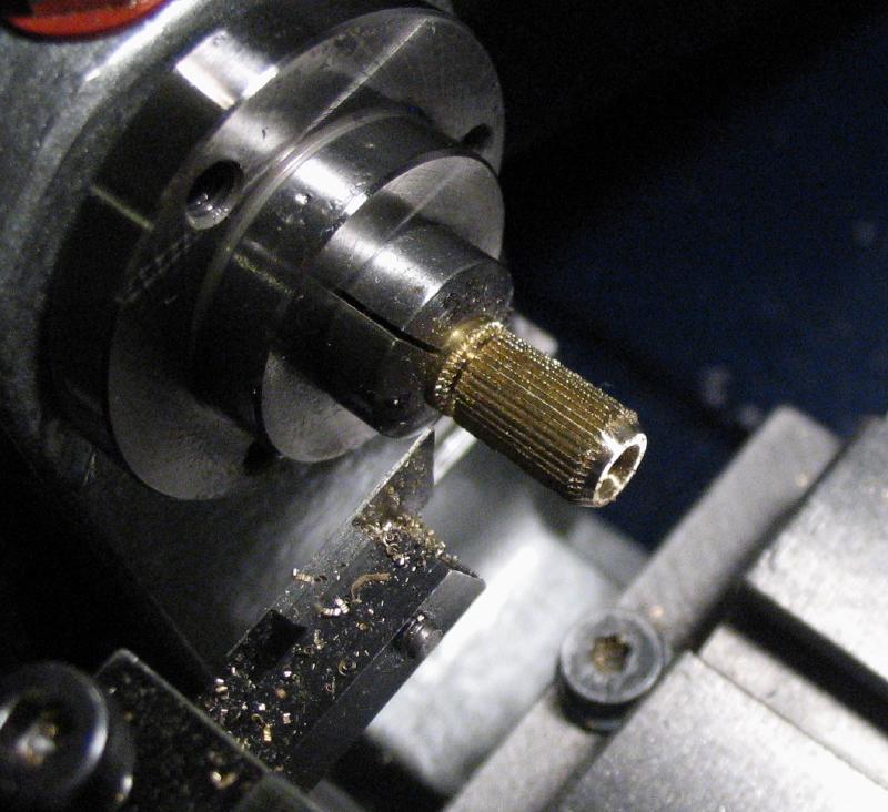
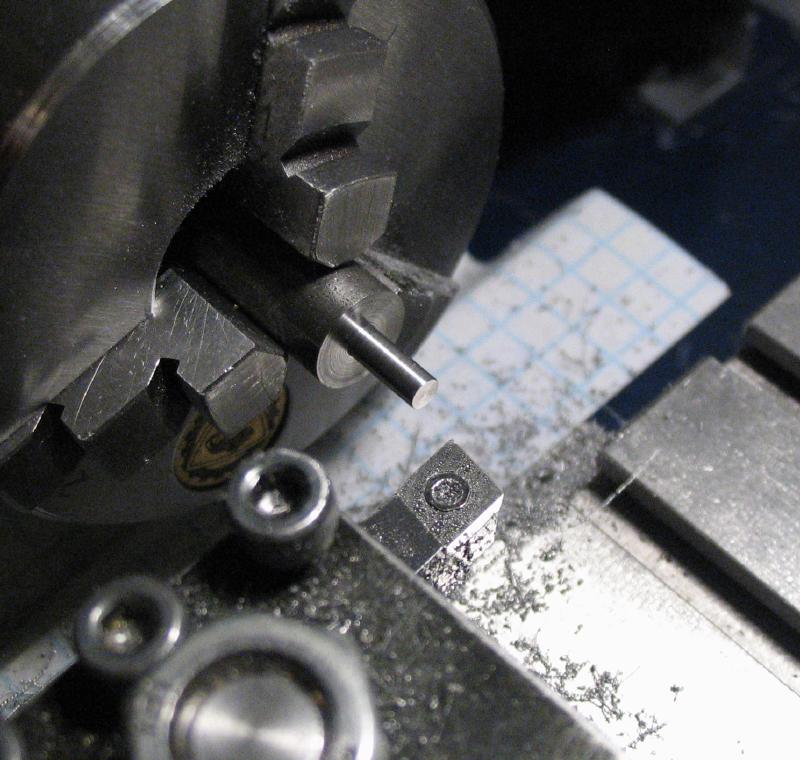
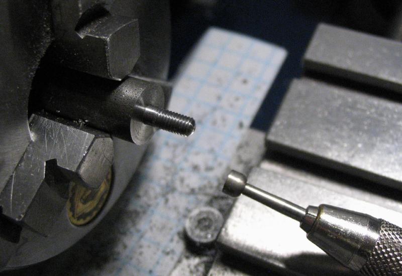
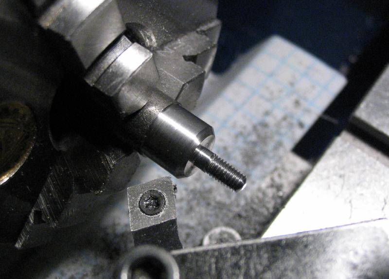
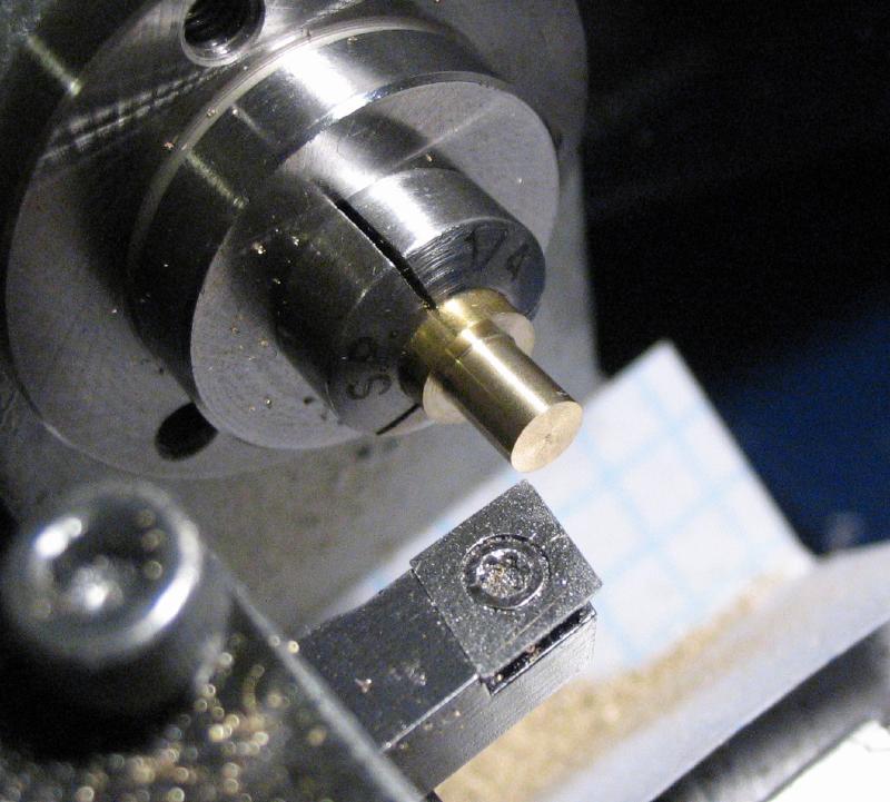
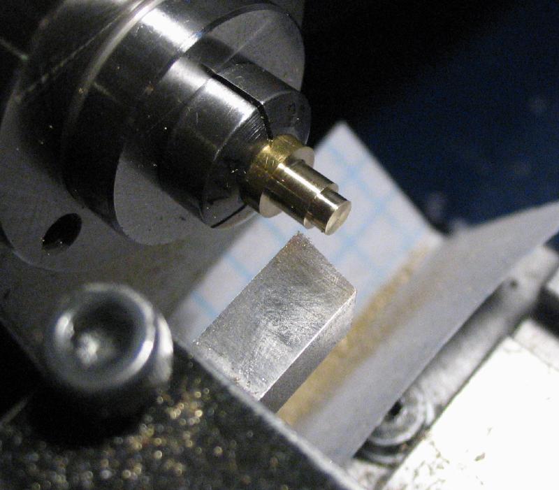
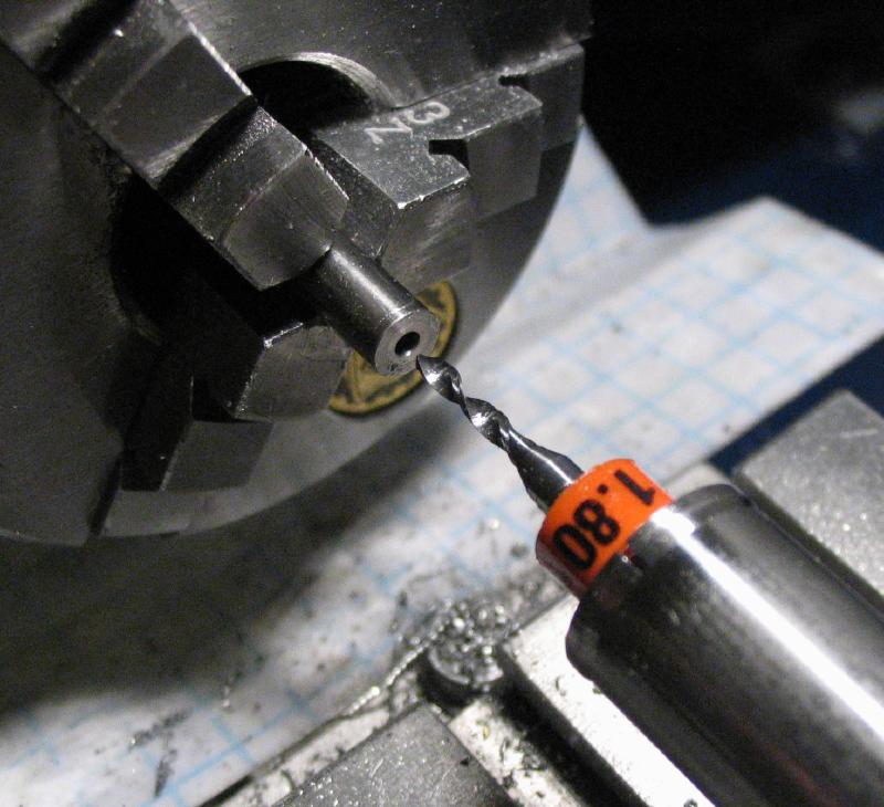
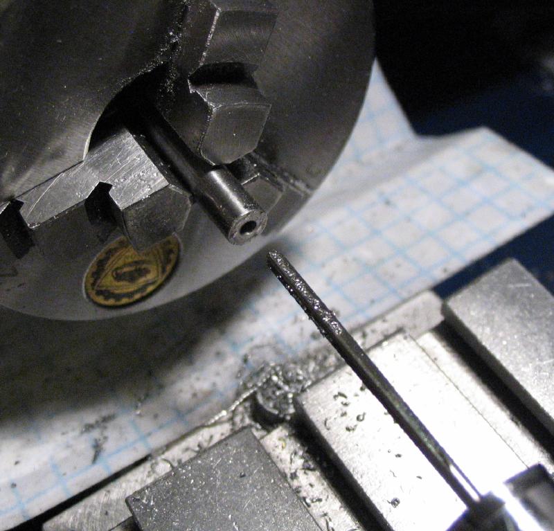
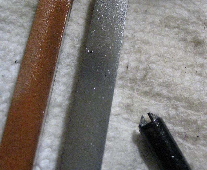
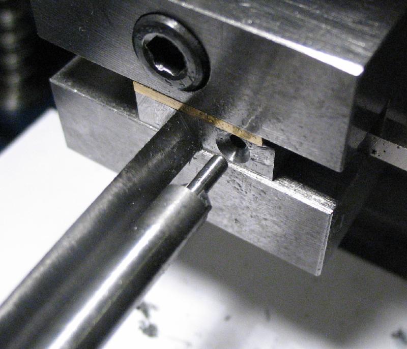
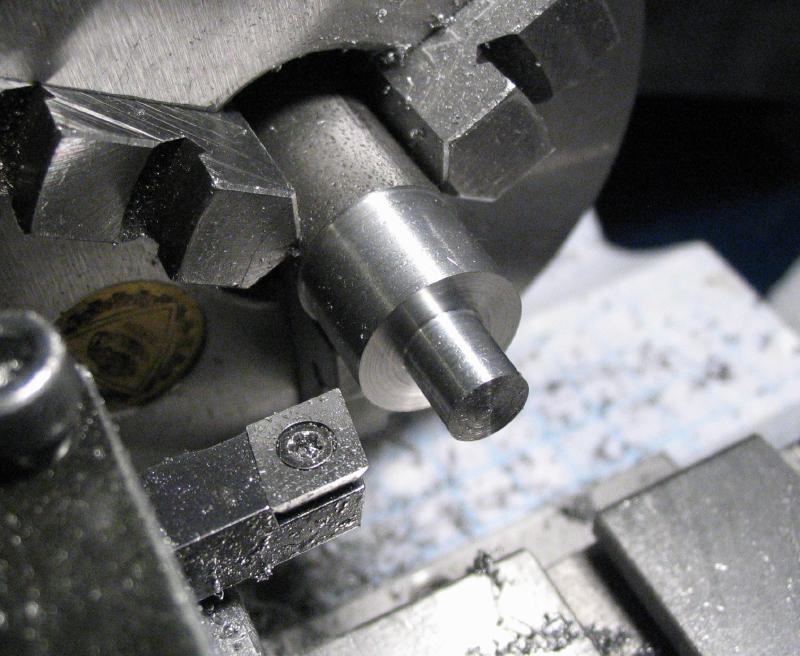
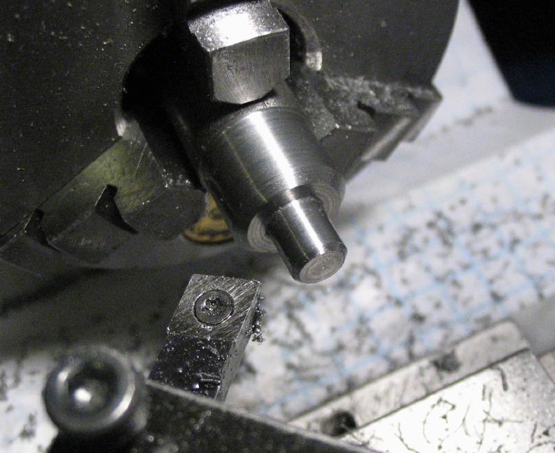
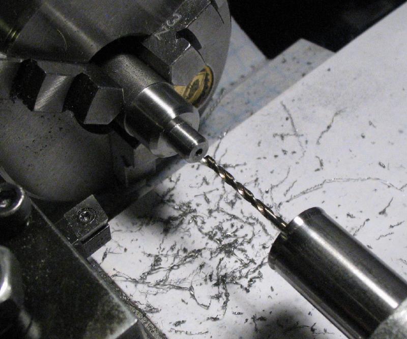
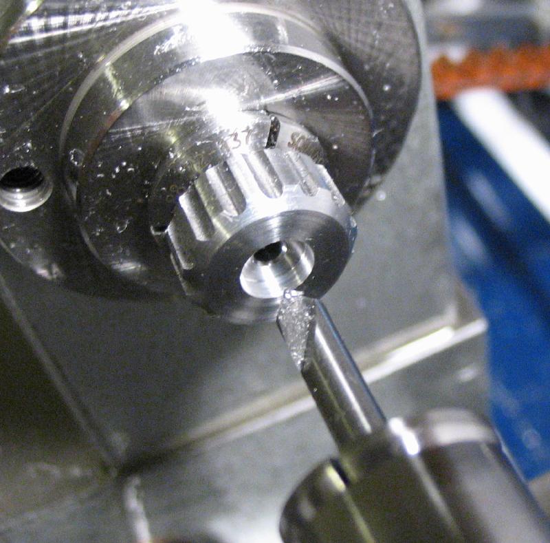
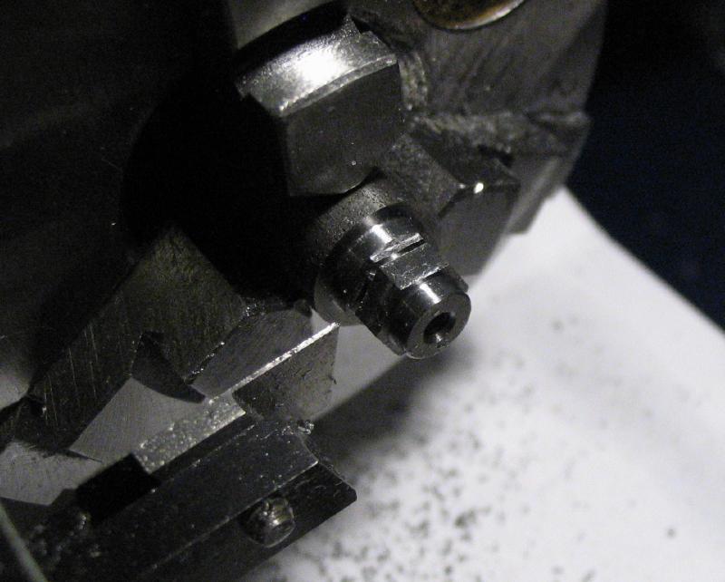
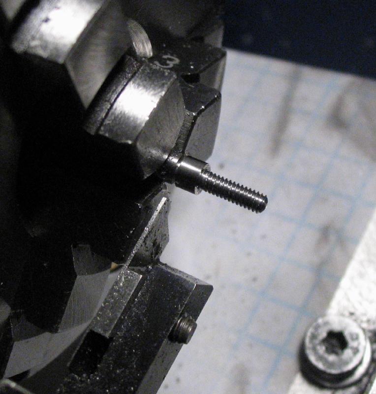
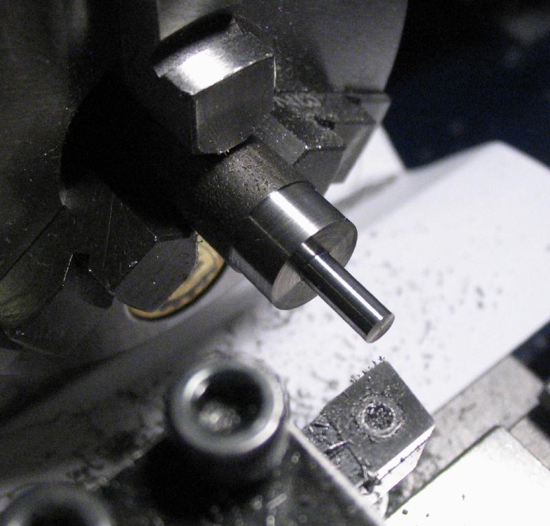
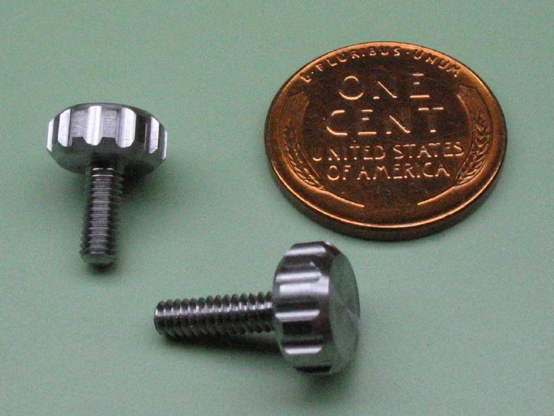
A thumb screw was made for locking the position of the cone center. A length of 3/8" cold roll steel rod (12L14) was turned to 3mm diameter for 7.5mm length. The screw will need to clear the lower portion of the tool, so the length is slightly oversized. A portion of this was threaded M3, and the end rounded over with a cup bur. The rod was extended from the chuck and turned down to about 9mm and the corner chamfered.
|
|
|
|
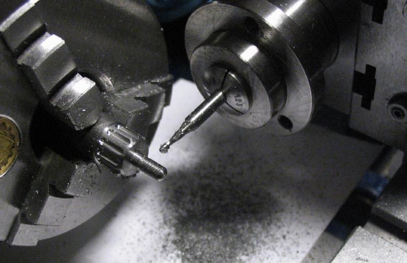
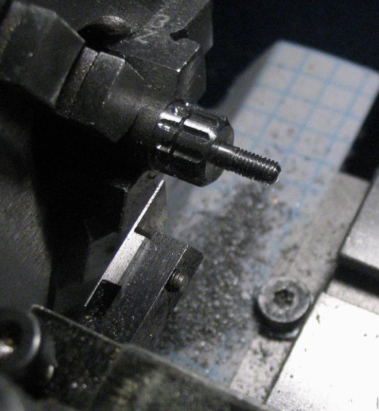
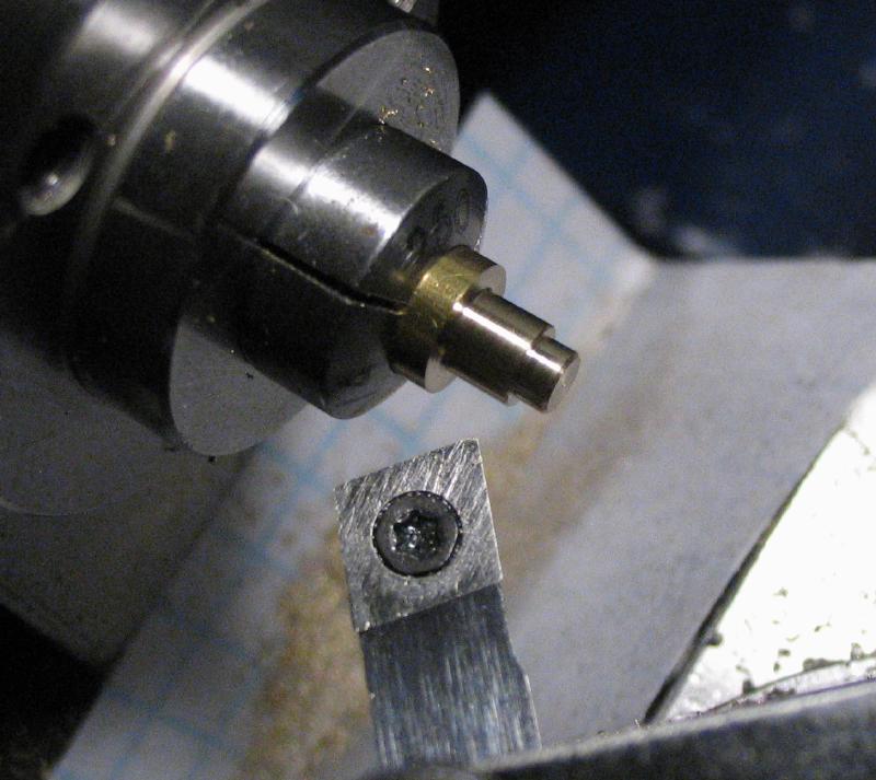
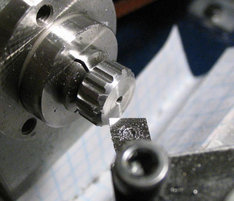
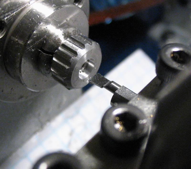
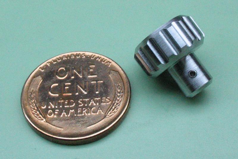
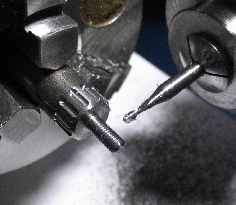
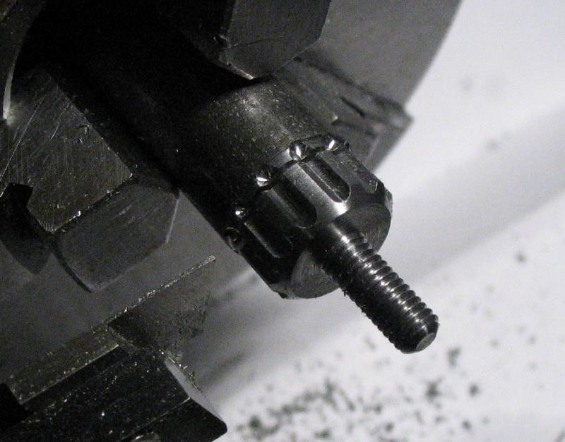
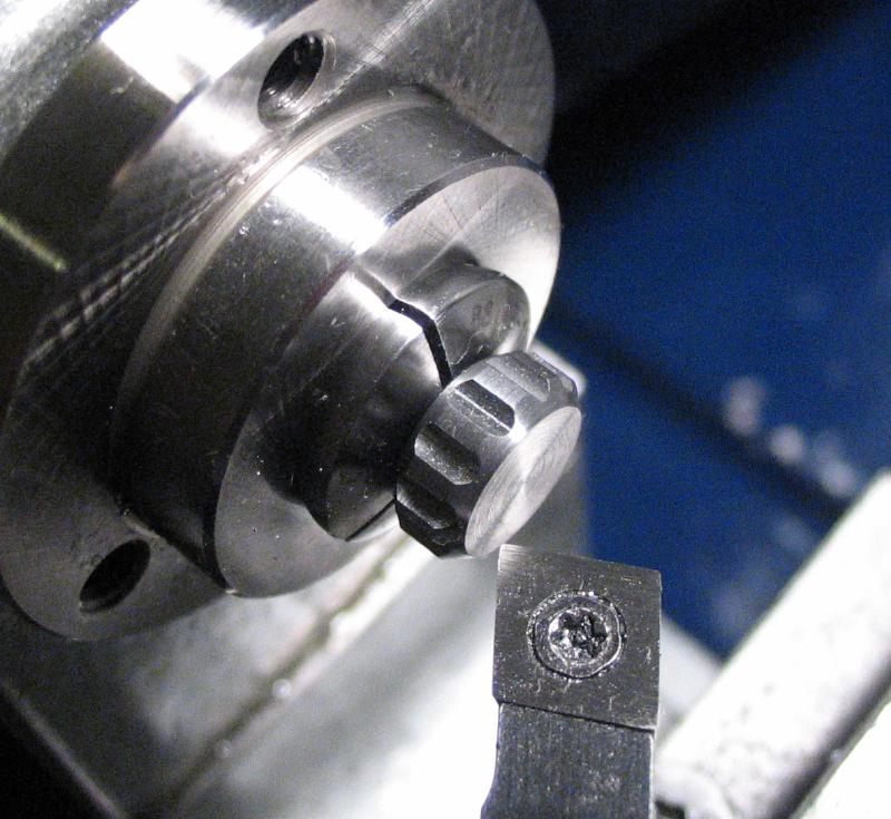
The thumb screw was milled with 12 grooves using a 1/16 diameter ball end mill to a depth of 0.5mm. The work was then parted off at a thickness of about 4mm. It was then reversed into a collet and the parted face turned and the corner chamfered to match.
|
|
|
Another test fitting...
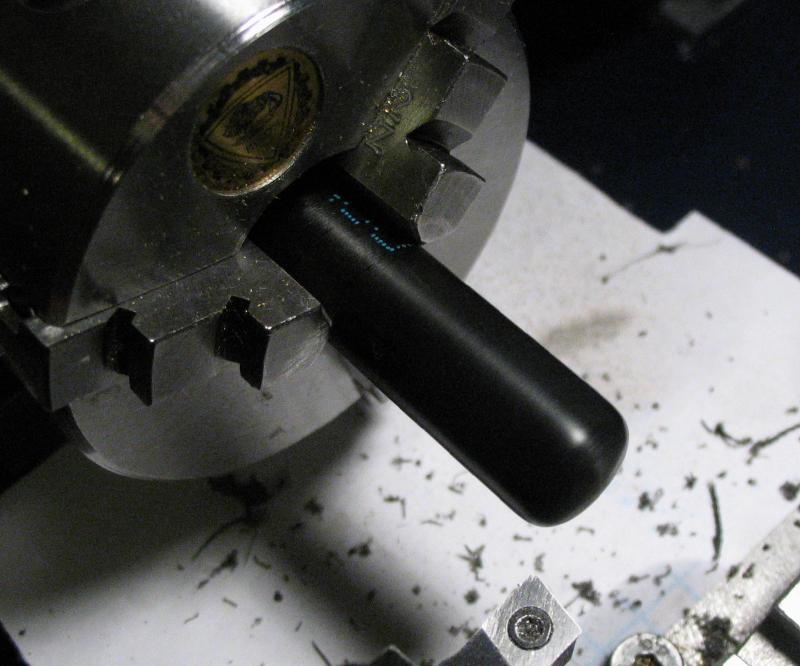
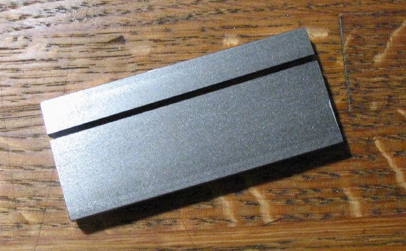
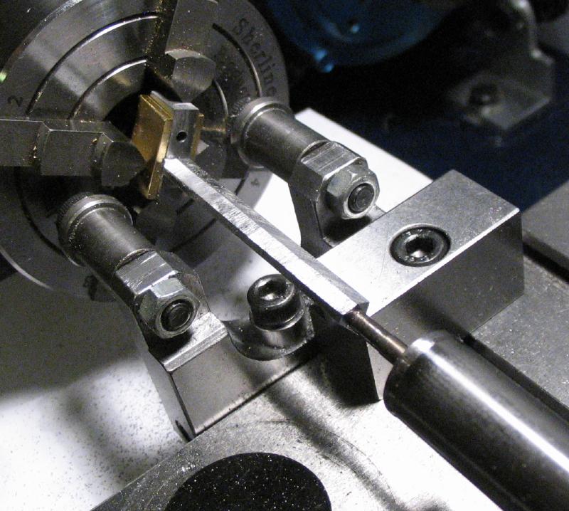
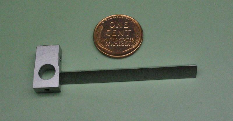
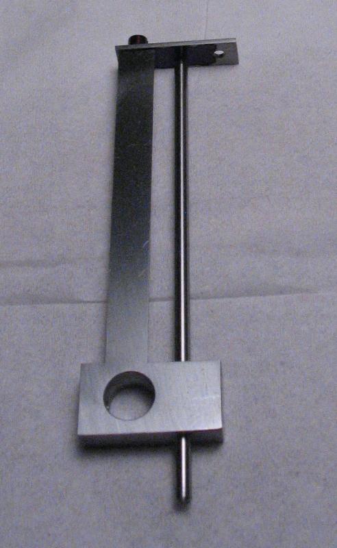
A length of about 57mm of 3/16" x 1" cold roll steel bar (1018) was sawed off and the ends squared up by milling. The width was reduced by sawing; the Hand-i-Hack tends to cut at a slight angle, something I've intended to address but is only significant on long cuts, so the bar ranged in width from 17.4 to 18mm. This edge especially and the others were squared up by milling, and the bar was about 57x17mm when done and this includes some excess.
|
|
|
|
|
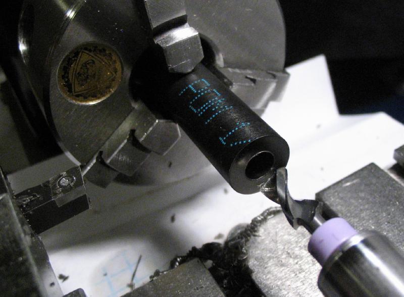
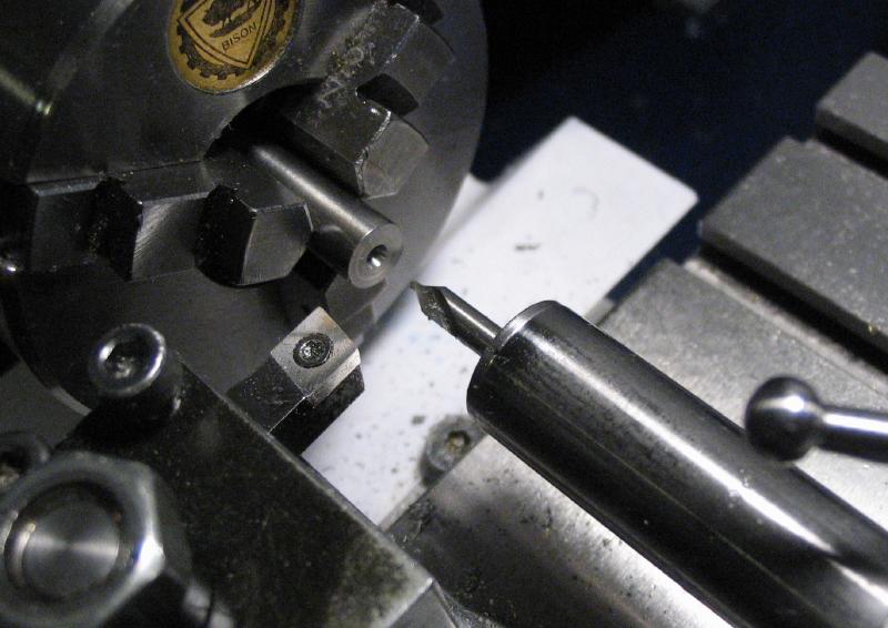
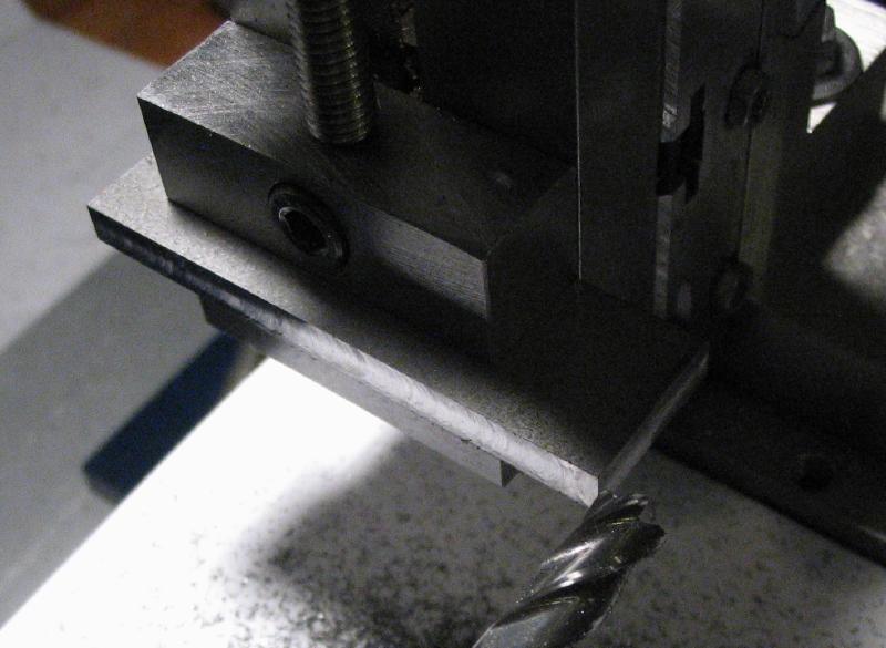
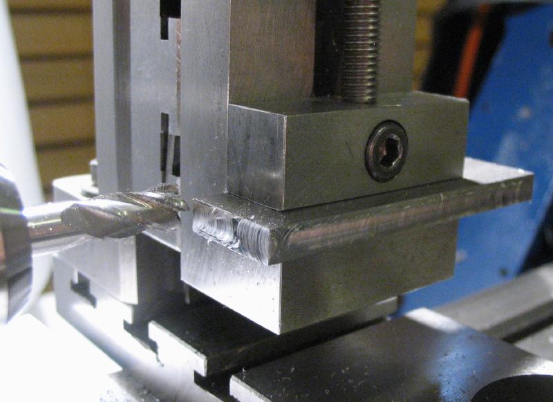
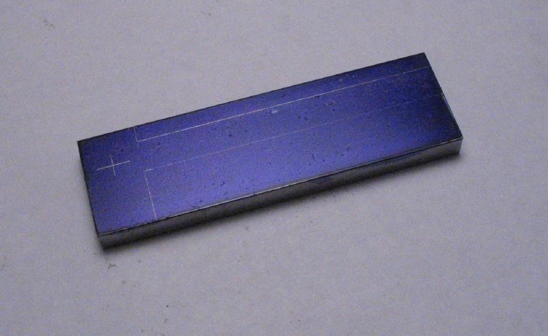
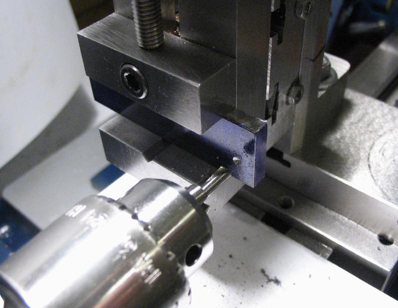
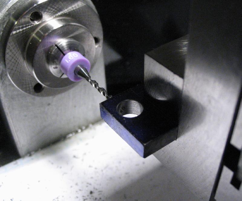
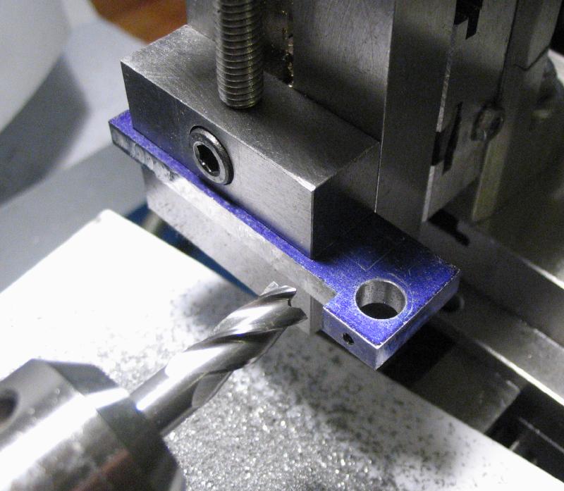
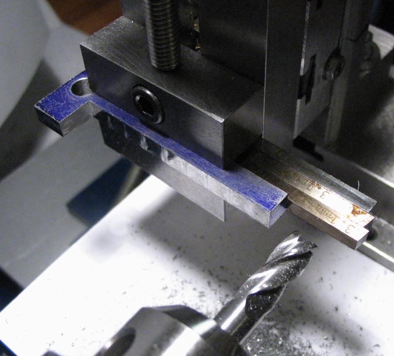
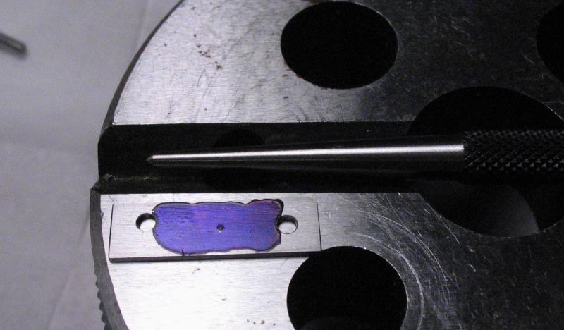
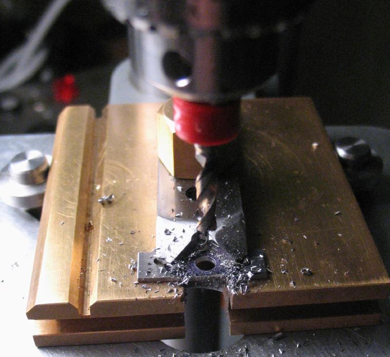
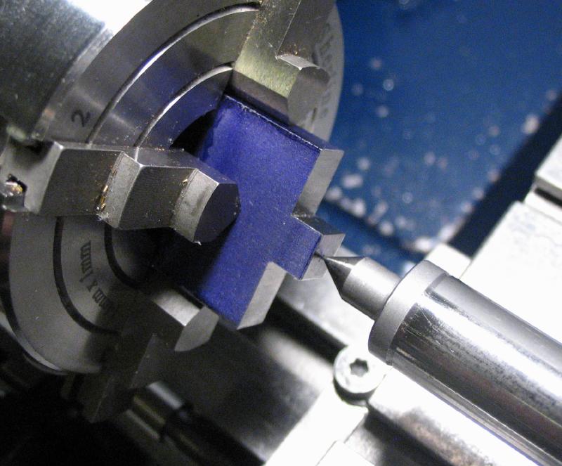
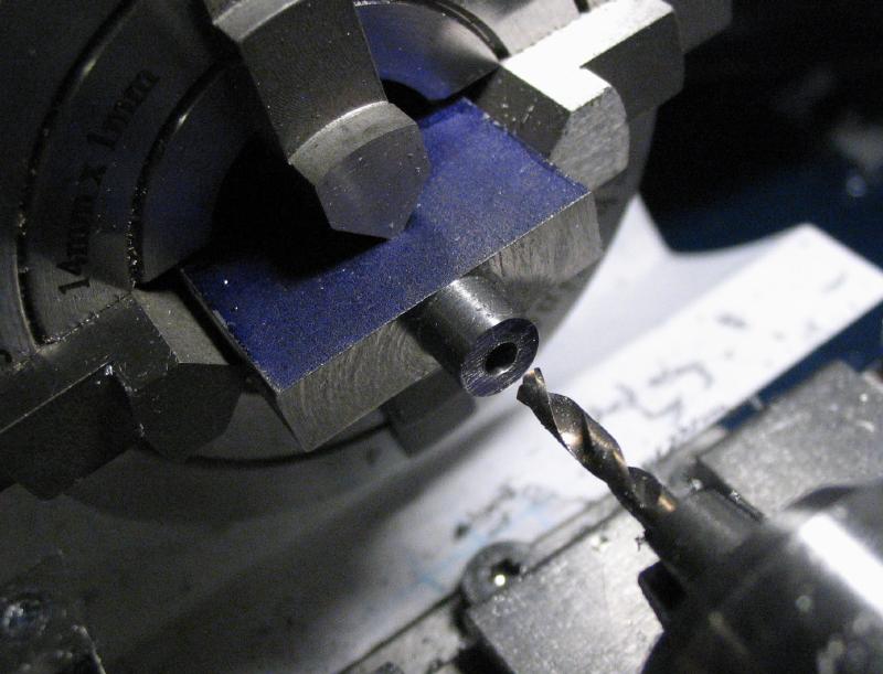
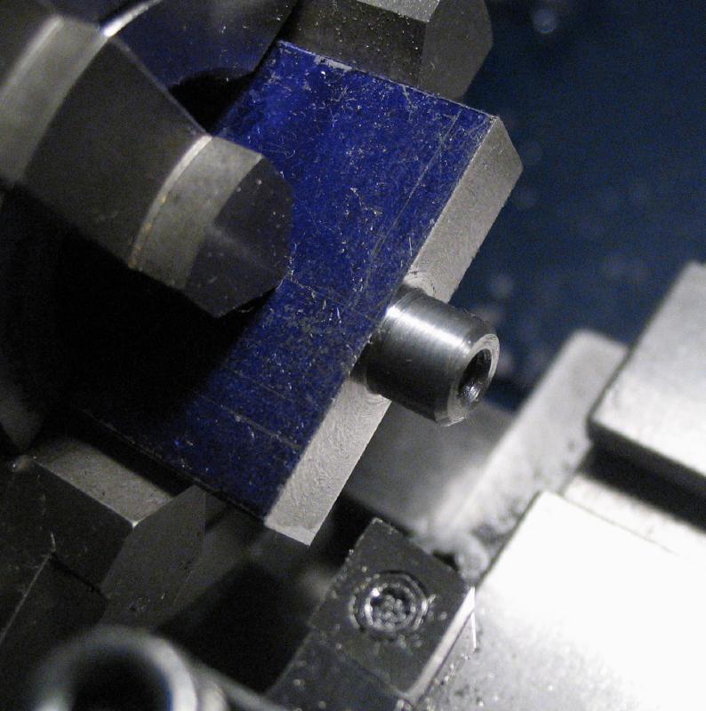
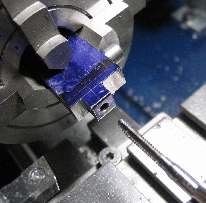
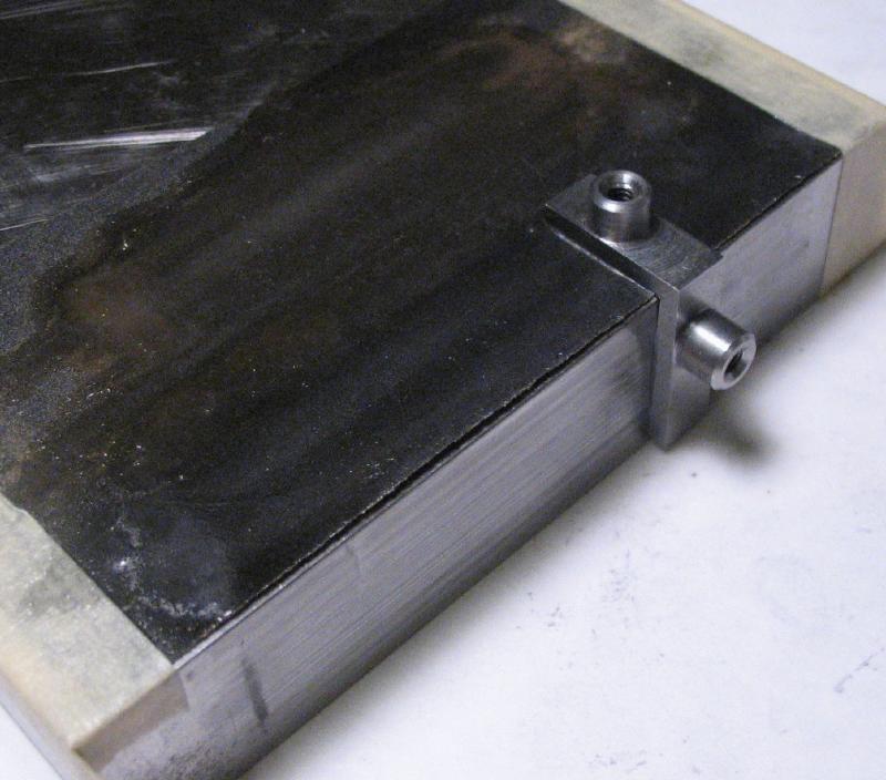
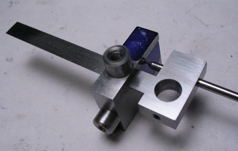
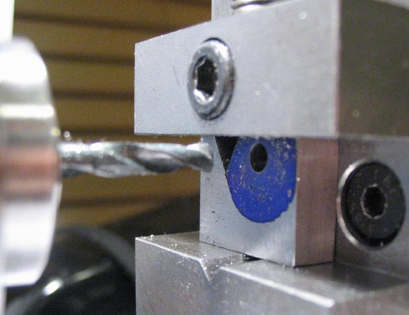
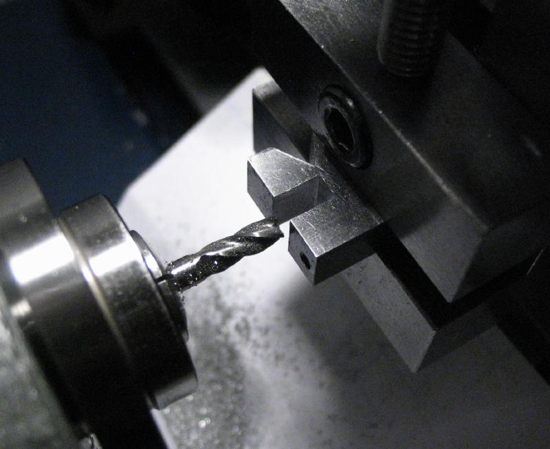
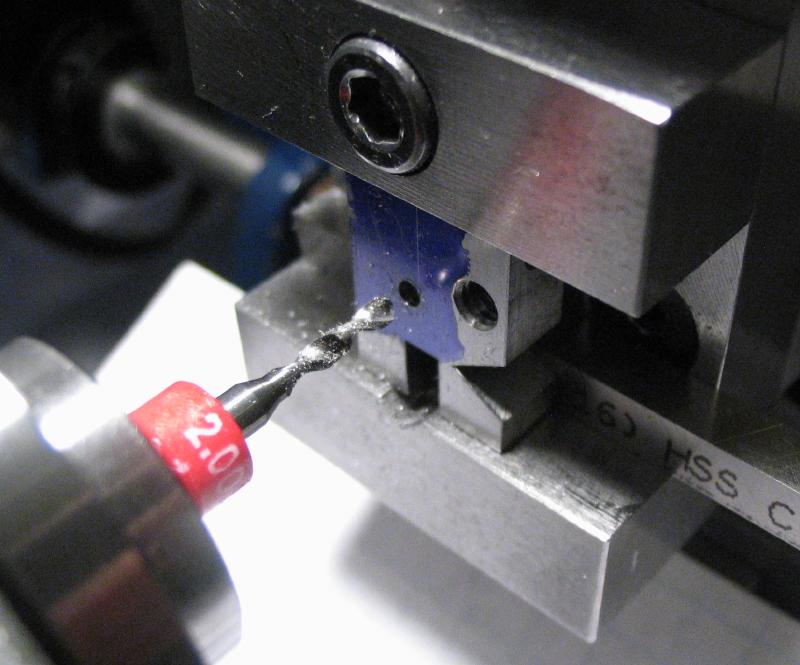
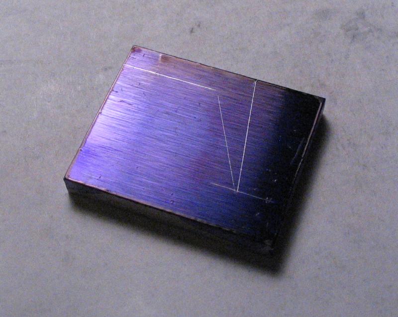
The steel bar was coated in Dykem blue and the location for the hole for the shaft and its set screw were marked out. Some of the other basic dimensions were scribed as well, although these are approximations. The bar was moved to the machine vise and the marked position found, spot drilled, drilled 5.8mm, and then reamed 6mm. The hole was lightly countersunk to remove burs.
|
|
|
|
|
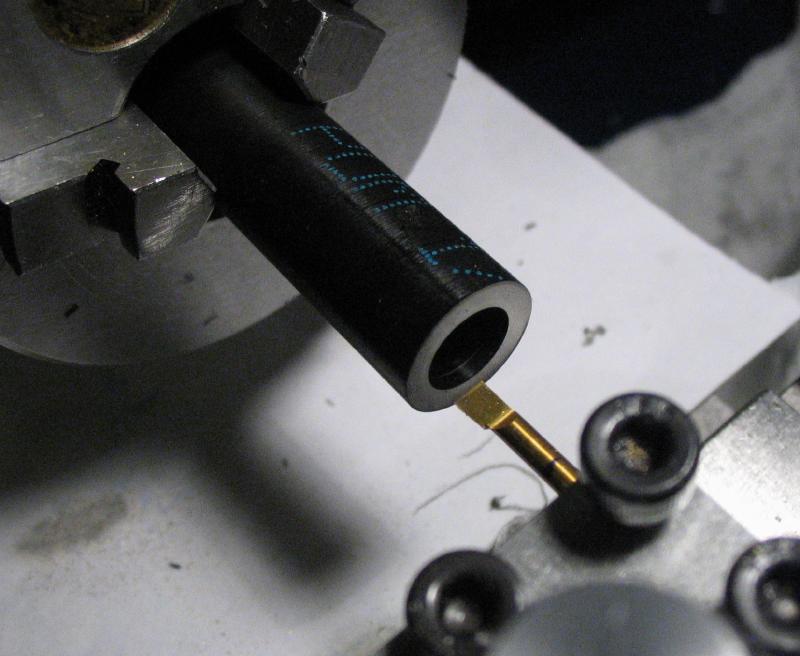
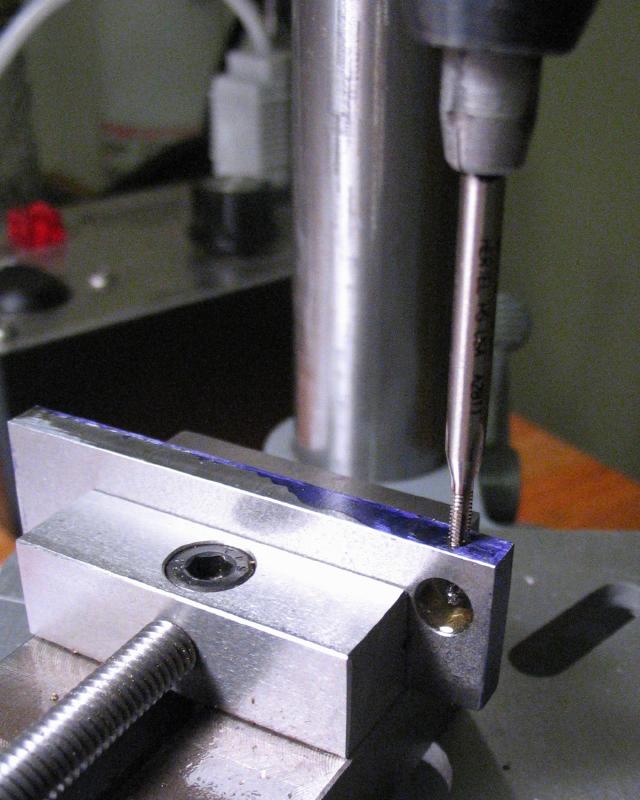
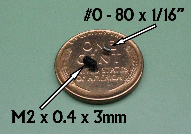
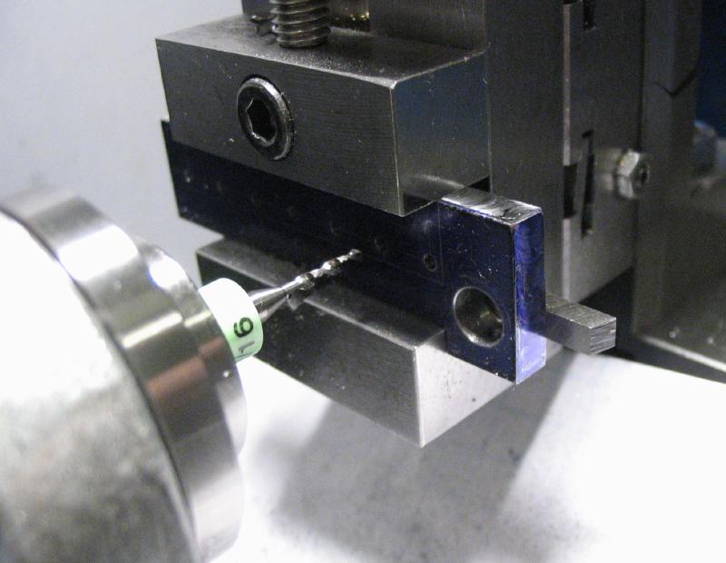
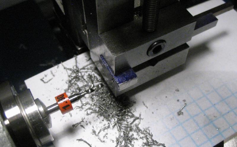
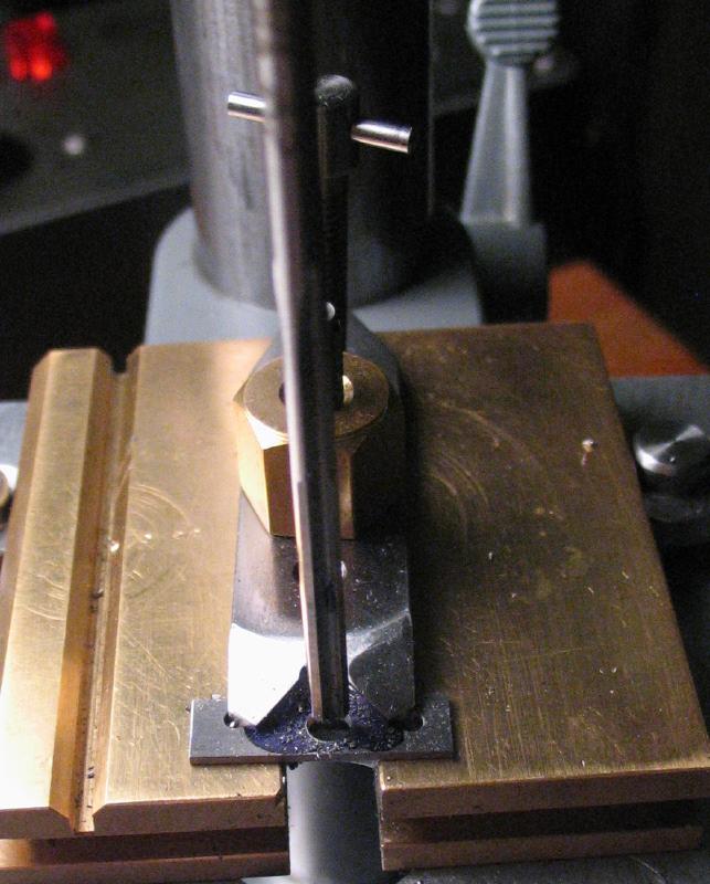
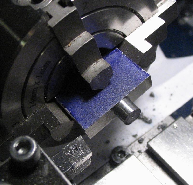
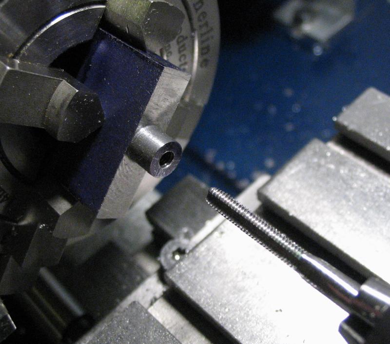
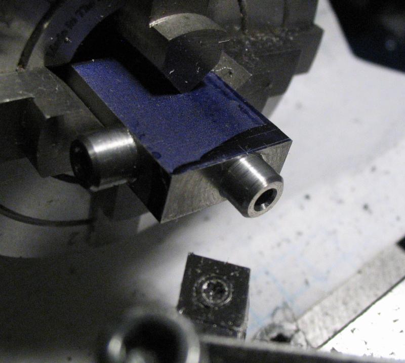
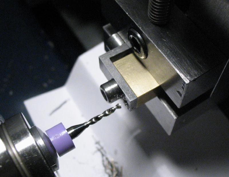
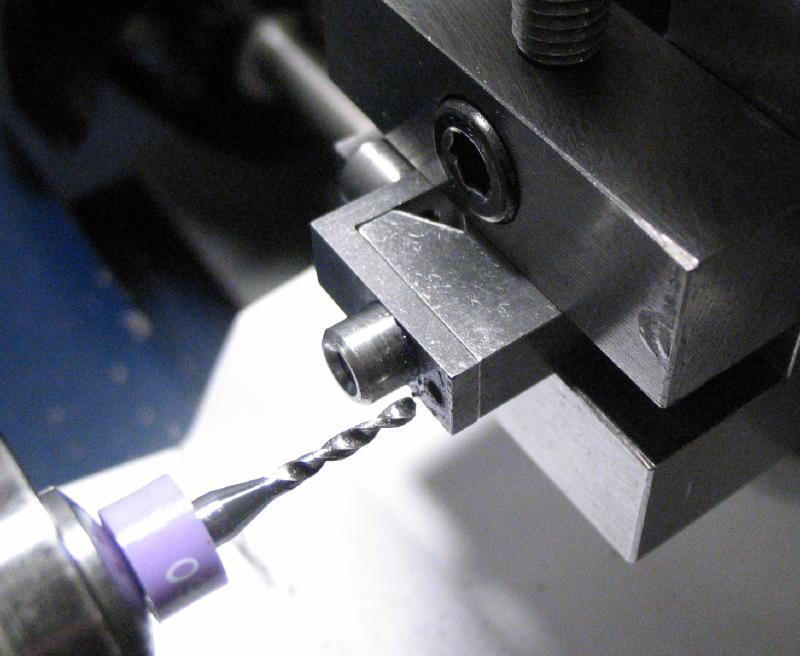
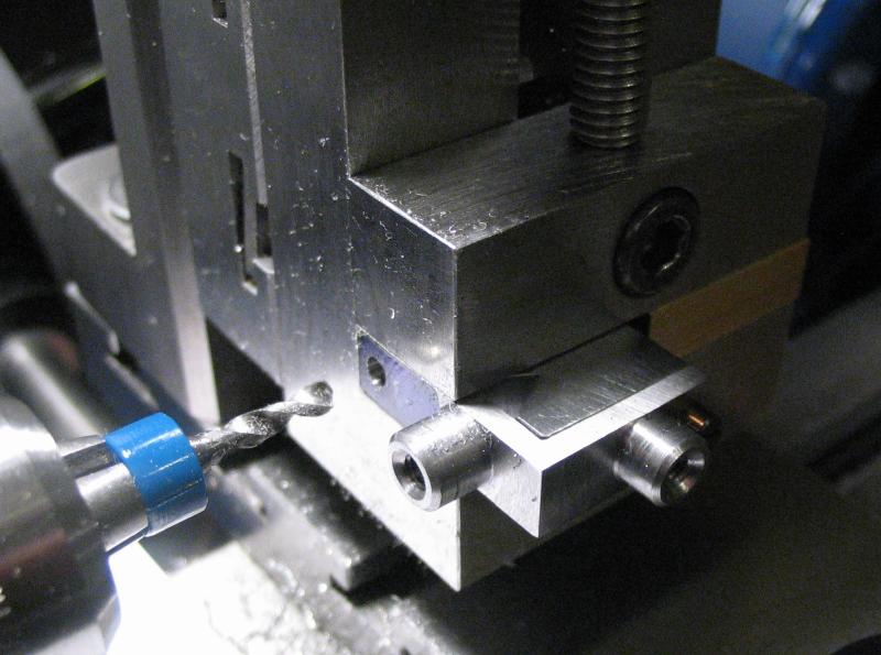
The bar was returned to the vise, and the hole for the set screw drilled 1.6mm and then tapped M2x0.4. A couple very small set screws were purchased for this project and shown below - M2 x 3mm and #0-80 x 1/16". Another test fit was in order, and appears that the thumb screw for the center point can be shortened a bit, but this was expected.
|
|
|
|
|
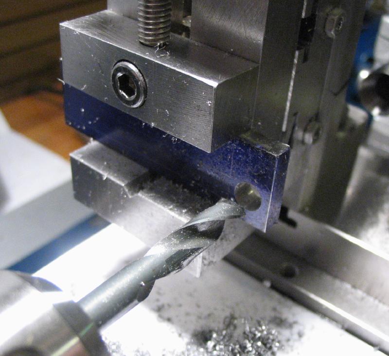
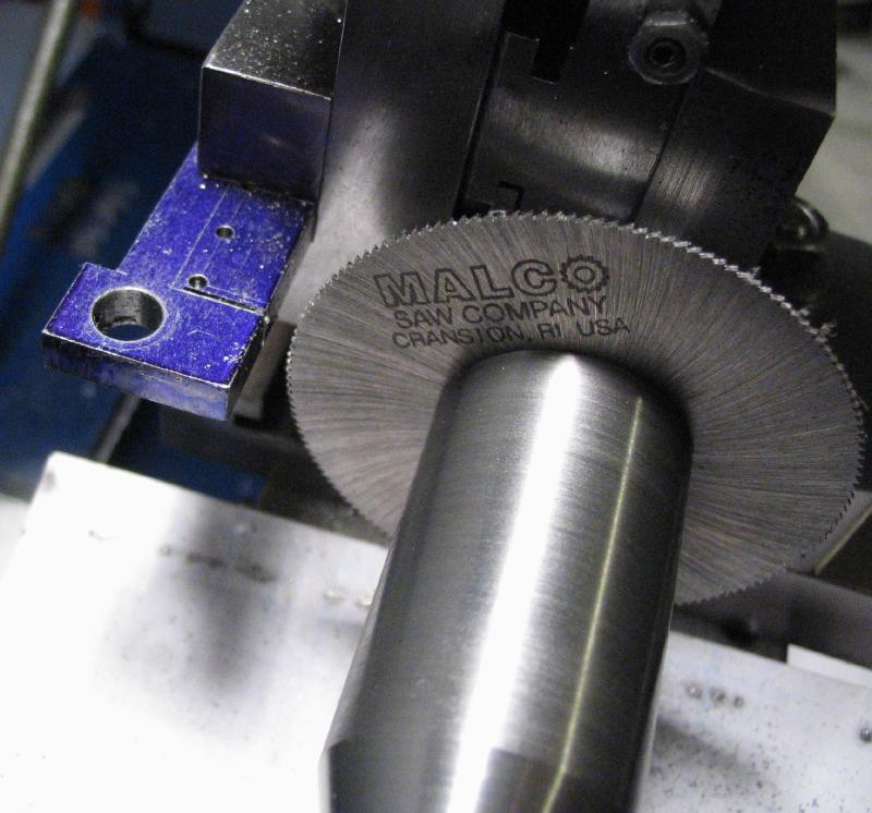
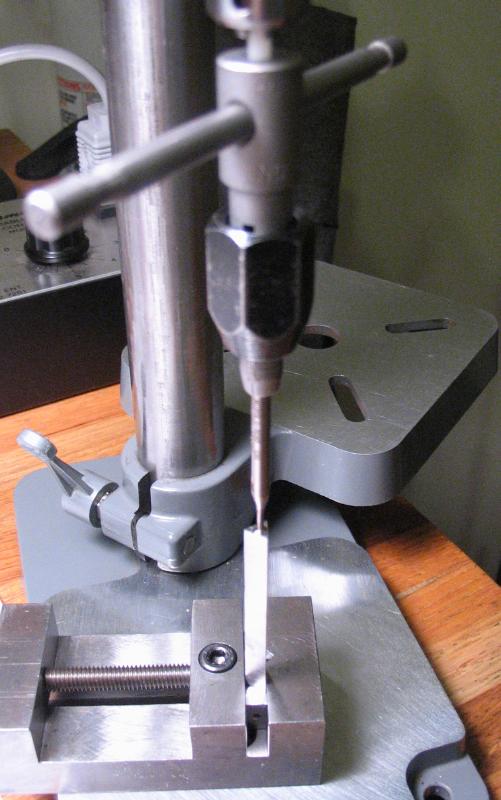
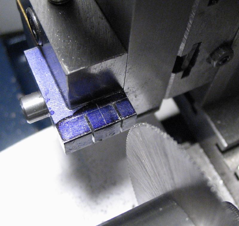
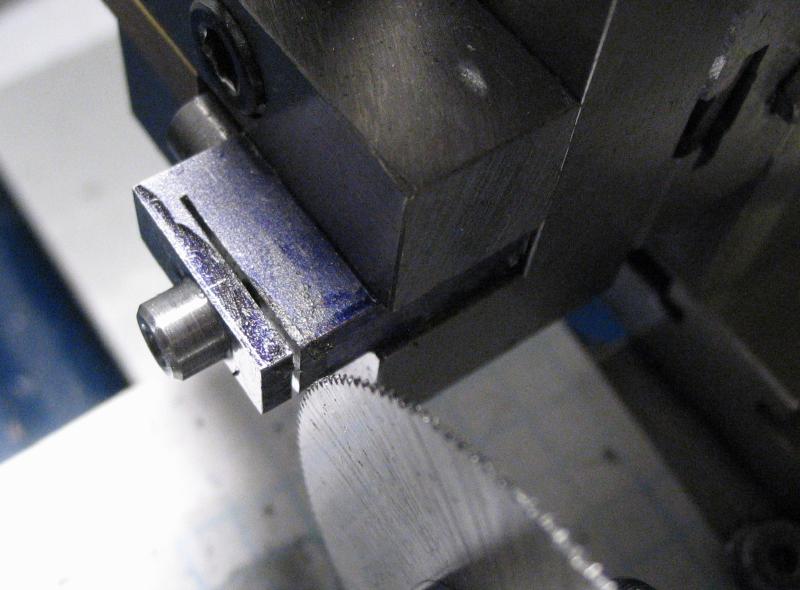
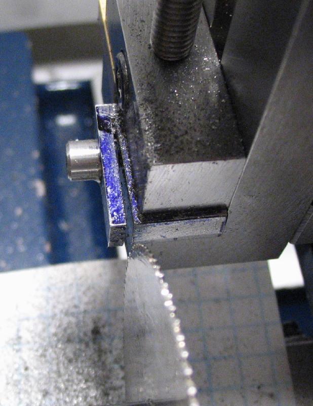
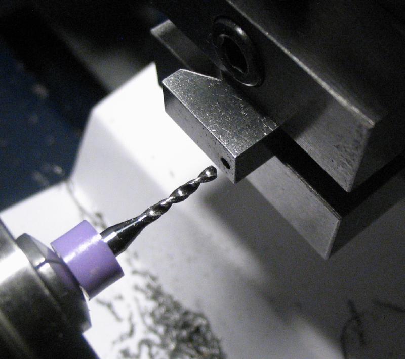
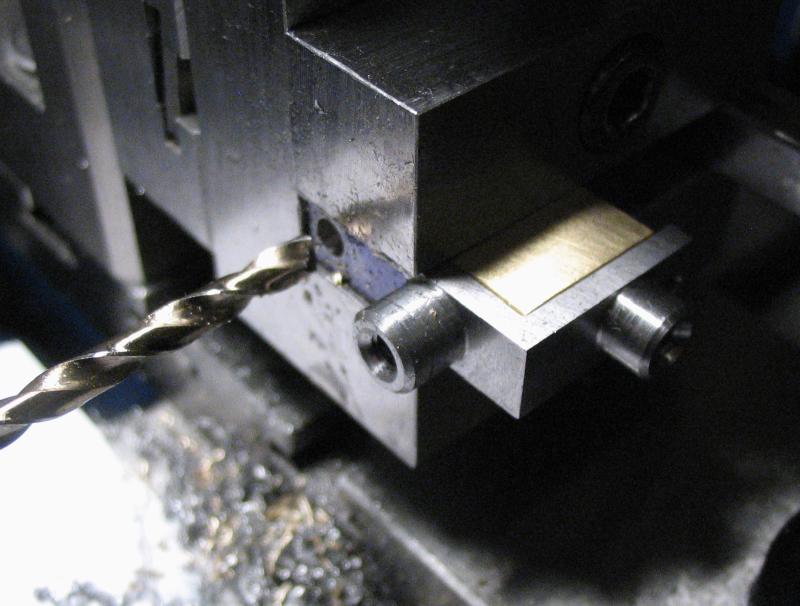
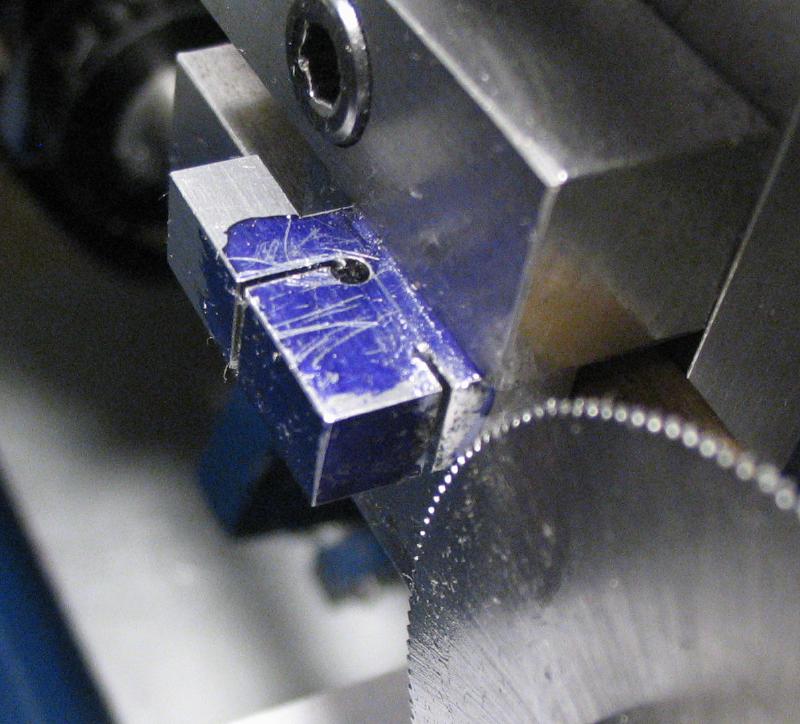
The steel bar was returned to the vise and 3mm removed from the front edge with an endmill to form the start of the guide rail. The reverse side was sawed to remove the bulk of the stock. Since sawing a straight line by hand is challenge for me, I drilled 1/16" holes along a sawing line at a safe distance from the final width. The holes are 7mm apart and provide a convenient place to pause and relubricant the saw blade. The work was re-positioned and a slotting saw used to make a perpendicular cut. It was also an excuse to try out a recently made saw arbor.
|
|
|
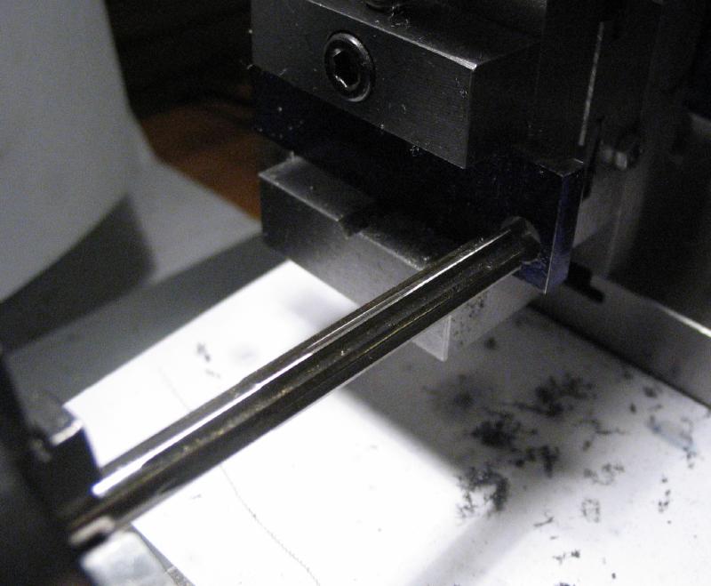
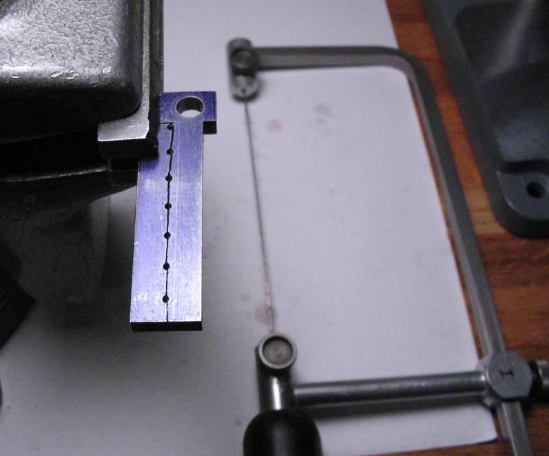
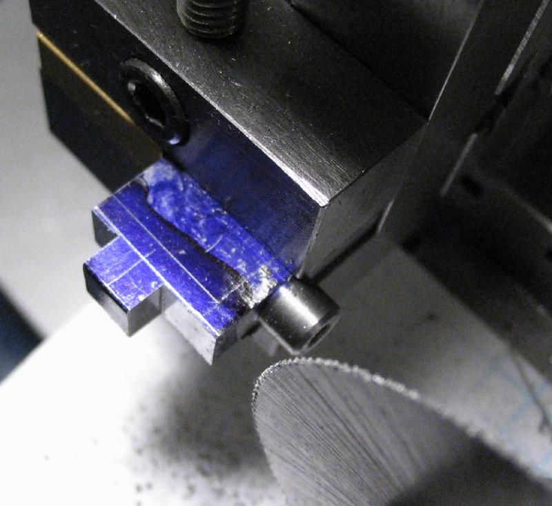
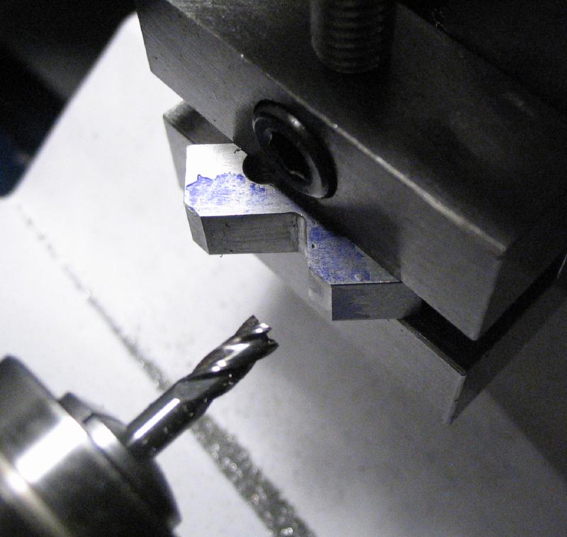
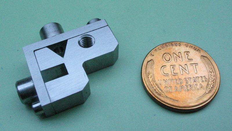
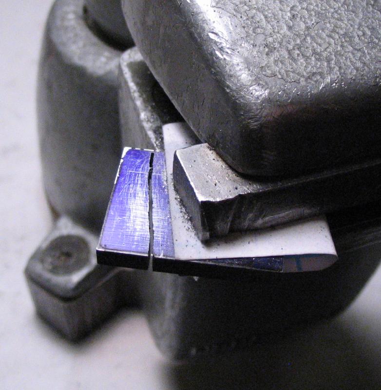
The surplus material was sawed out with a #6 jewelers saw blade. The edge was then squared up and brought to a final width of about 5.2mm. I am planning to form a triangular shape that will act as the guide for the scribing point assembly. The height will need to be under 3/16", so for 4.5mm geometry rules give a width of 5.196mm.
|
|
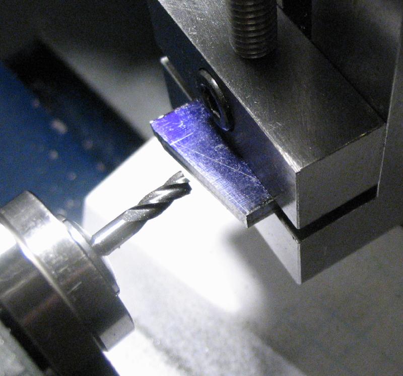
A hole was made that will act as one of bearings for the feed screw. It was drilled 1.8mm and then reamed 2mm.
|
|
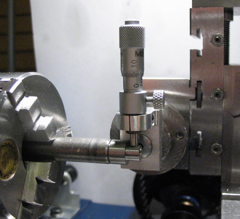
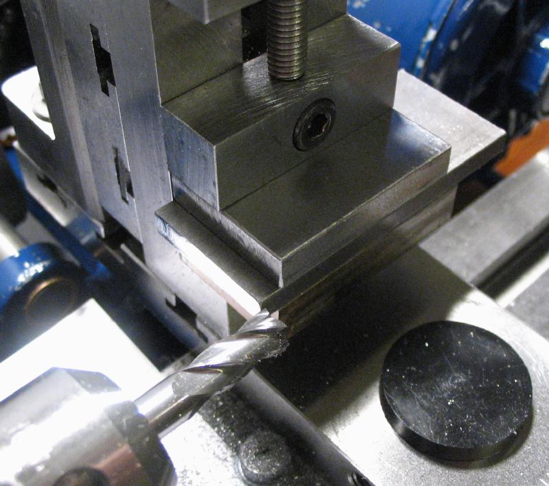
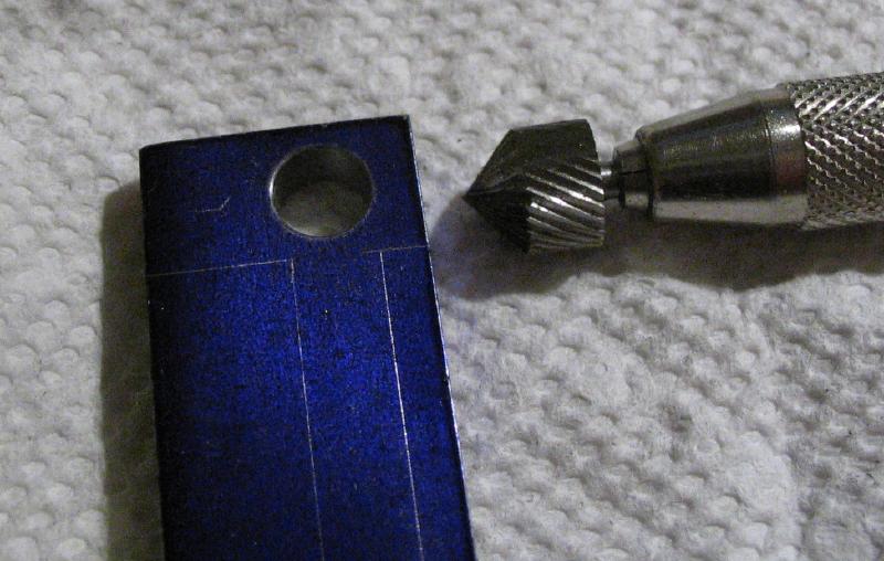
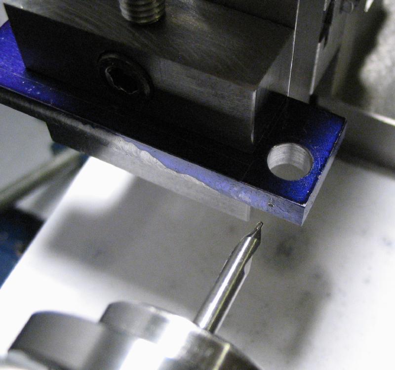
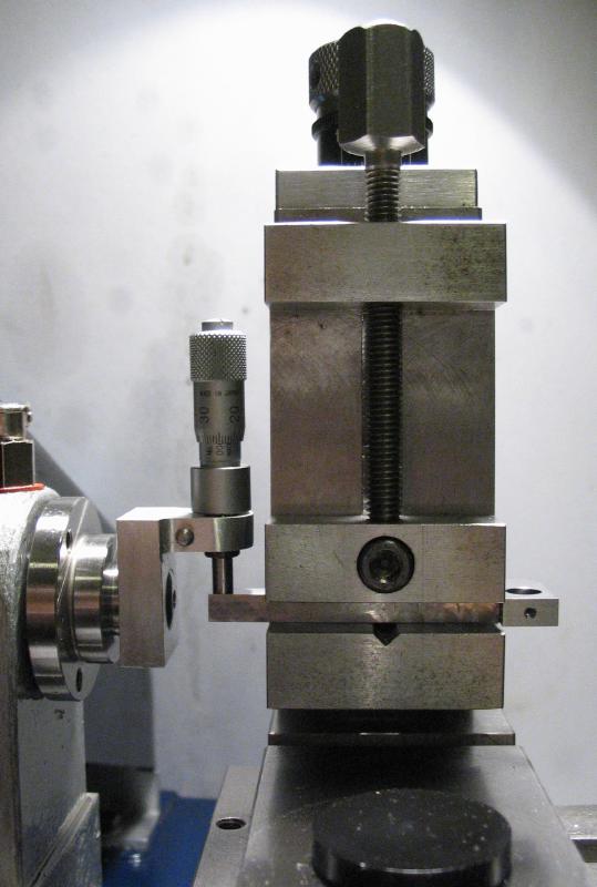
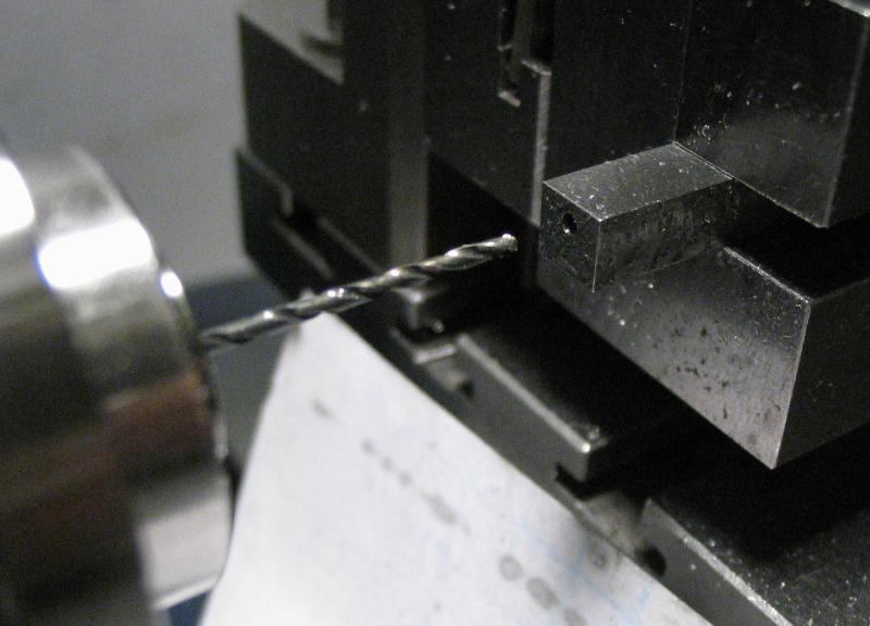
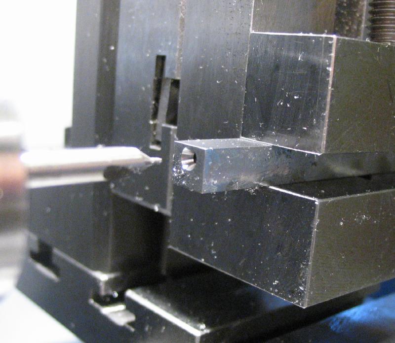
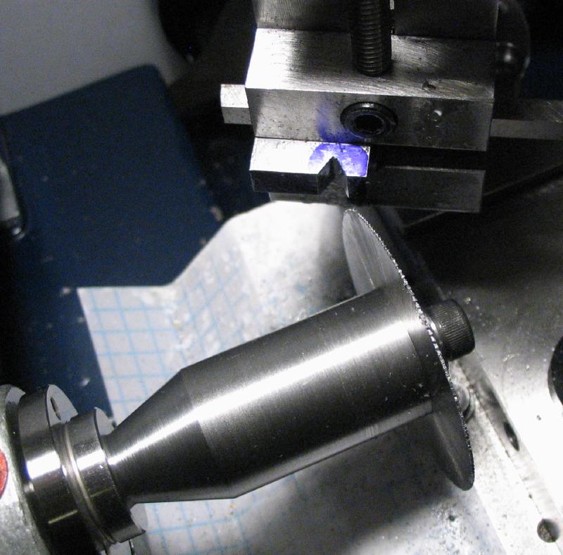
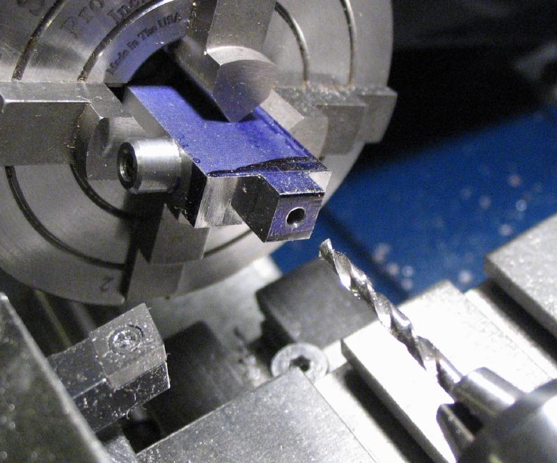
The bar was setup in the machine vise and positioned using the micrometer centering tool so that lathe center is 1.5mm from the top face and centered with the bar. The position was spot drilled, drilled 3/64" for tapping #0-80 later on, and the hole then countersunk 60 degrees.
|
|
|
|
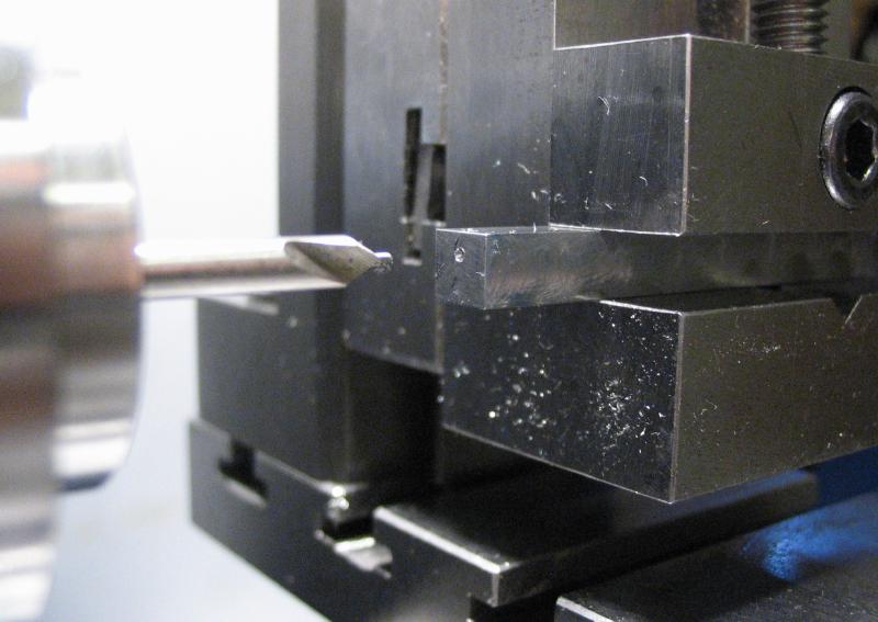
A male cone tailstock center was made from 1/8" oil hardening drill rod. It was turned down to 2.9mm to just clear the file in use and given a 30 degree taper to match the countersunk hole in the end of the bar. The center was hardened and tempered to about a straw/brown color. The other end of the center rod was turned to 2.5mm for perhaps another use since it can just as well be double ended.
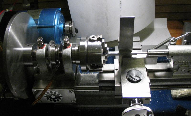
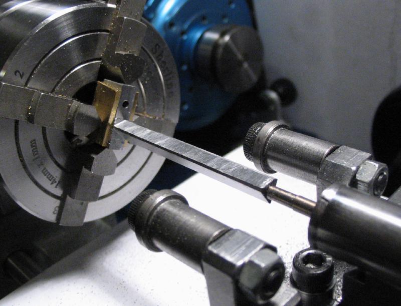
The work was setup in the independent four-jaw chuck and the tailstock center used for support. The setup is relatively simple, but difficult to describe. I am planning to use the indexing plate to provide the necessary angles, but it needs to be "zeroed in" first, which involved a little trickery. The indexing plate adapter was installed onto the headstock spindle but only loosely tightened, both it's own locking screws and the tightness against the spindle bearing. A square was placed on the cross slide and the top face of the work made upright. The first photo is the first of a several attempts at getting this squared up. I added pieces of brass plate under the chuck jaws to help hold the work evenly. The 120 count index plate was locked by first tightening the index plate adapter on the spindle to move the plate to the next closest locking position. The locking screws on the adapter were then tightened up at this point as well. The work can then be indexed about, as needed, in 3 degree increments with reference to the top face. I could not manage to find a setup to mill the two other faces of the triangular guide, and decided to file them by hand. The Cowells filing rest was installed on the lathe and was lowered with the cross slide feed. Measurements were taken with a micrometer while filing the work to check progress and the bar was left at a width of about 4.6mm when filing the first side. The work was then indexed to the third face and the process repeated. I used my coarsest file on hand, a Nicholson "mill-bastard" and finished with a No.2 Grobet hand file and various needle files for smoothing high spots. The file rest needs to be moved along and the work filed in steps.
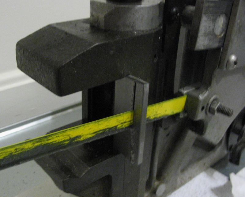
After filing one of the two sides
|
First pass of filing the second face.
|
Second pass with the coarse file.
|
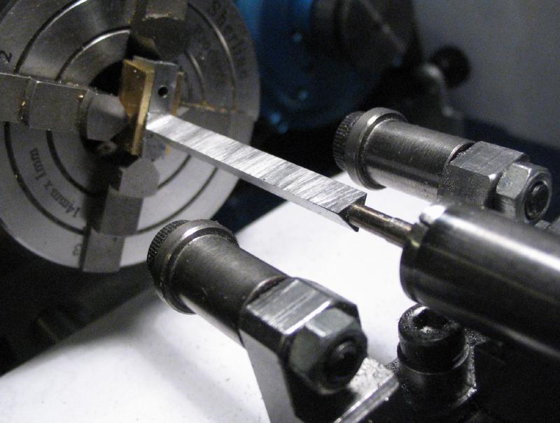
After the final passes of filing, and smoothing high spots.
|
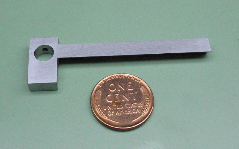
This is quite a bit of filing, and the filed areas will still need some hand finishing, but I am saving this for later when fitting the mating components and will likely need some alterations. Shown is the work after removing it from the lathe and cleaning up.
|
|
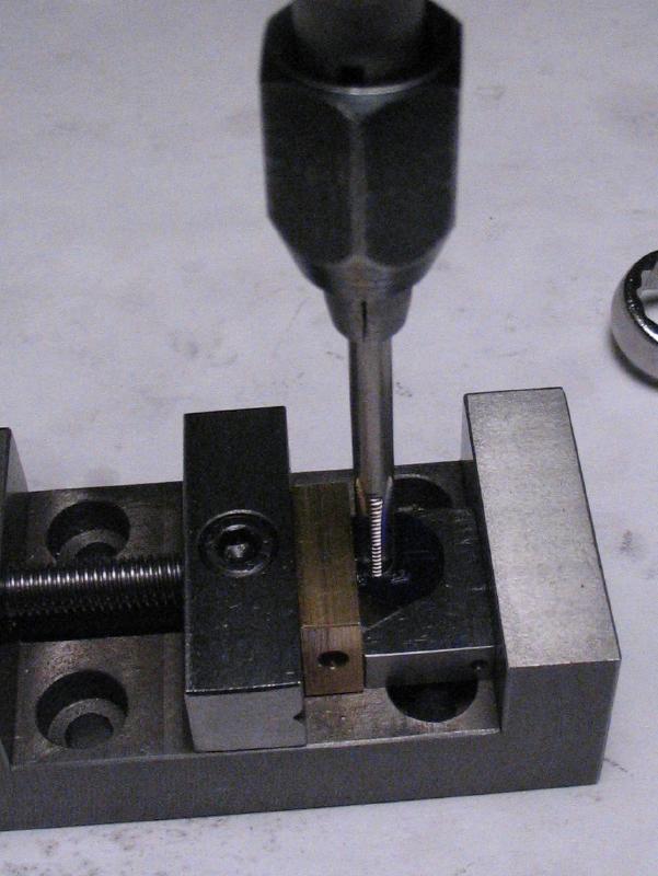
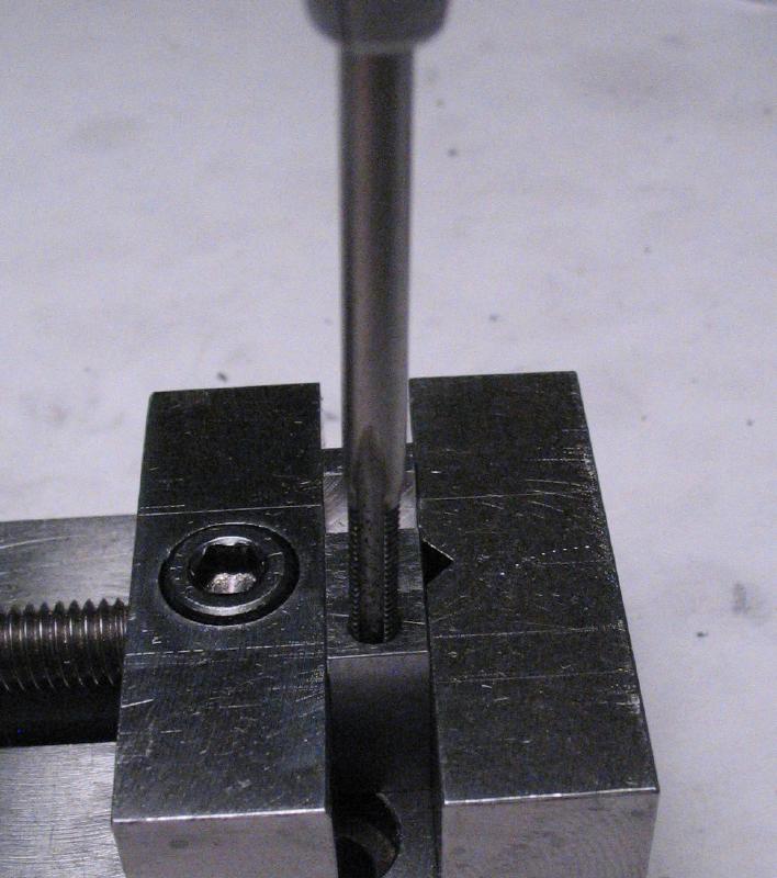
The guide bar was held in the vise on the drill press to tap the end hole #0-80. This is an awkward setup, a relatively deep blind hole, and a small size, so tapping was carried out carefully and at about a quarter turn at a time before backing out. Some TapMagic cutting oil was used as well.
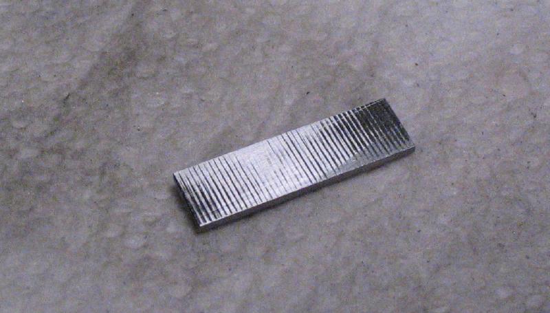
A small bracket was started that will attach to the end of the guide bar and hold a bearing for the screw feed rod. The bracket was made from 1/32" thick oil hardening gauge plate. A piece a little over 5mm width and 20mm or so long was sawed off. The surface of the stock is fairly coarse, and is shown in the photo after rubbing on a No.6 file for a few strokes. It was smoothed with the file and on 400 grit emery paper. A misplaced hole was drilled, but this end will be cut away. A 1.6mm hole was drilled to attach the bracket to the guide bar with a #0-80 screw.
|
|
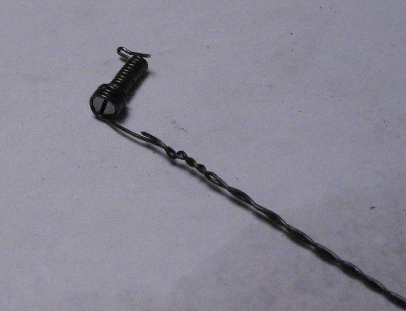
A screw was made from 3mm drill rod. About 5mm was turned down to 1.52mm and threaded #0-80. The screw head was parted off at about 2mm thick and flattened on 400 grit paper, and slotted with a 0.020" saw.
|
|
|
|
|
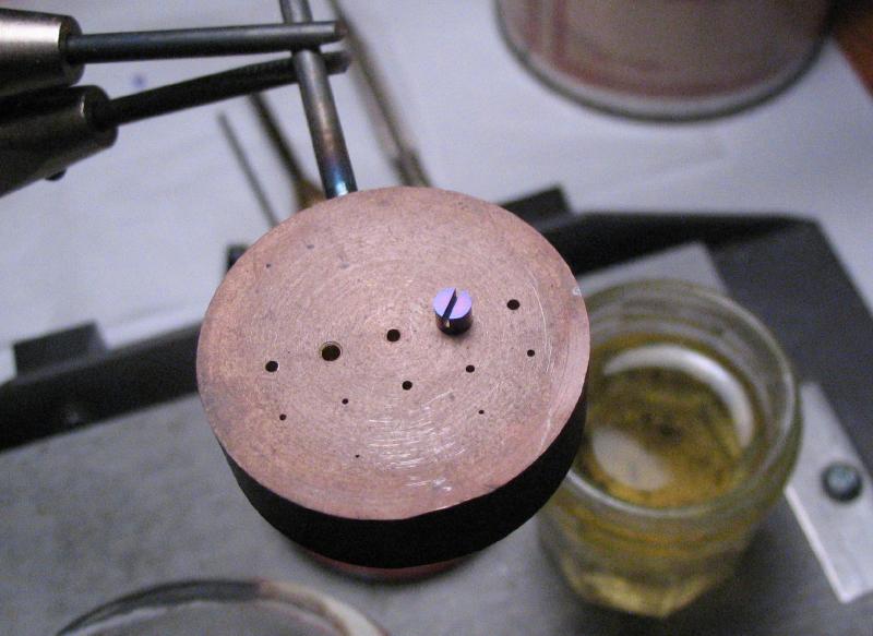
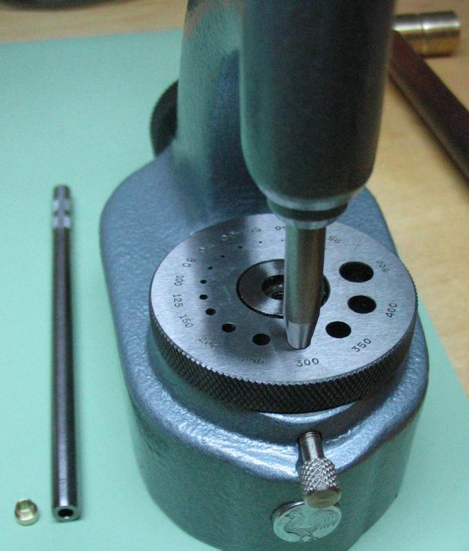
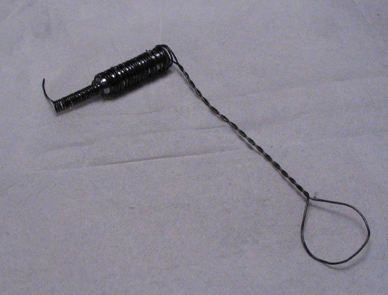
The screw wrapped in iron wire and hardened in oil, polished up again, and tempered blue using an alcohol lamp and a piece of drilled brass as a holder made specifically for doing such.
|
|
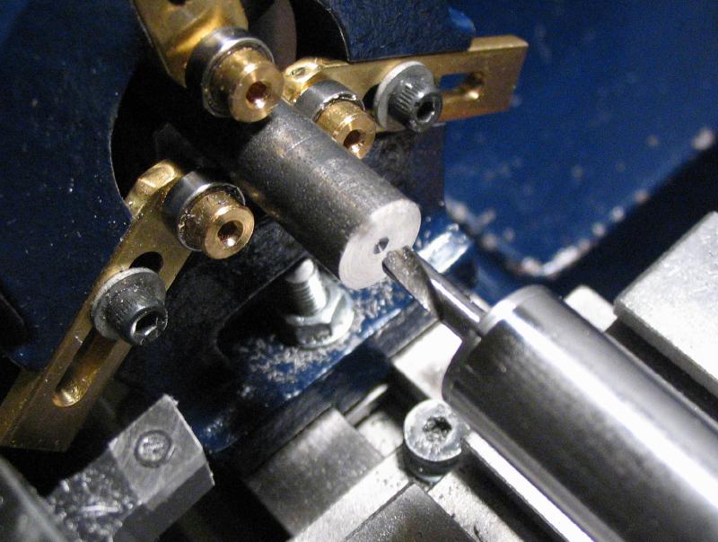
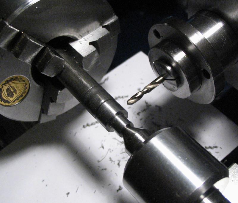
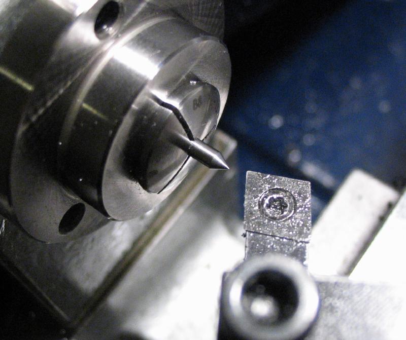
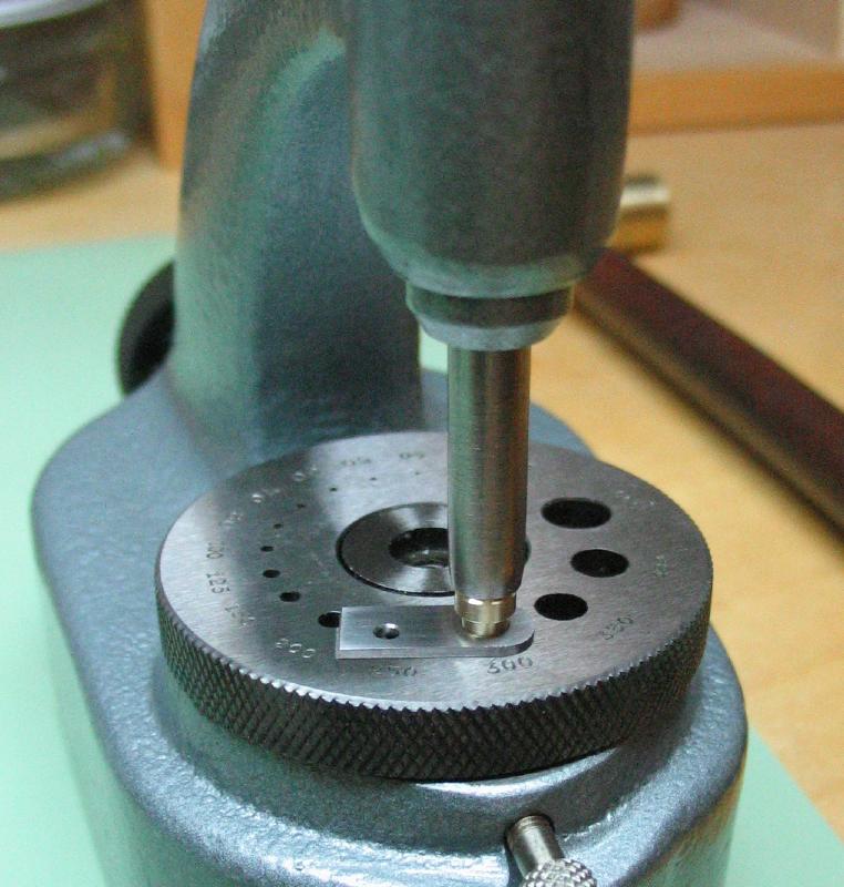
A point was turned onto the end of a length of 2mm drill rod for determining the location for the bearing. The bracket was coated in layout blue and installed on the guide bar. The 2mm rod was inserted into the tool and used to make a mark on the bracket. This mark was located with a prick punch and then center punched. It was returned to the drill press to drill and ream a 3mm hole.
|
|
|
|
|
A bearing was made from 1/4" brass rod (360 type). It was turned down to 4mm and a sharp tool installed for turning a length of 1.5mm down to 3.02mm. The corners were lightly chamfered 45 degrees and the rod drilled 1.8mm, reamed 2mm, and countersunk 60 degrees.
|
|
|
|
|
|
The bearing was parted off at slightly over 3mm length and the parted face turned true and chamfered and countersunk as well.
|
|
|
|
The staking tool was used to drive the bearing into the bracket. The bracket was shortened and roughly rounded over. It will be reduced to its final shape later after the guide bar is complete. The staking anvil plate was centered on the 3mm hole, however, I intended to use the 3.5mm hole since the bearing is slightly over 3mm to friction fit. I realized the mistake upon finding the bearing very nicely staked to both the bracket and the anvil! However, it was freed without too much struggle. The 2mm pointer rod was used to test the alignment of the bearing to the other bearing hole in guide bar body.
|
|
|
|
The hole in the guide bar body needs a bearing surface on the inside face to draw the screw feed rod into from the other side. I would have used a jeweler's 90 degree setting bur, but did not have a way to make it reach the hole. So a custom piloted countersink was made.
The countersink was made from 5mm oil hardening (O-1) drill rod. One end was faced and chamfered, and the working end faced, drilled 1.8mm, reamed 2mm, and then turned with a 45 degree taper. The milling spindle was installed and by indexing the headstock, opposing sides of the rod were milled, leaving the work 1mm thick.
|
|
|
|
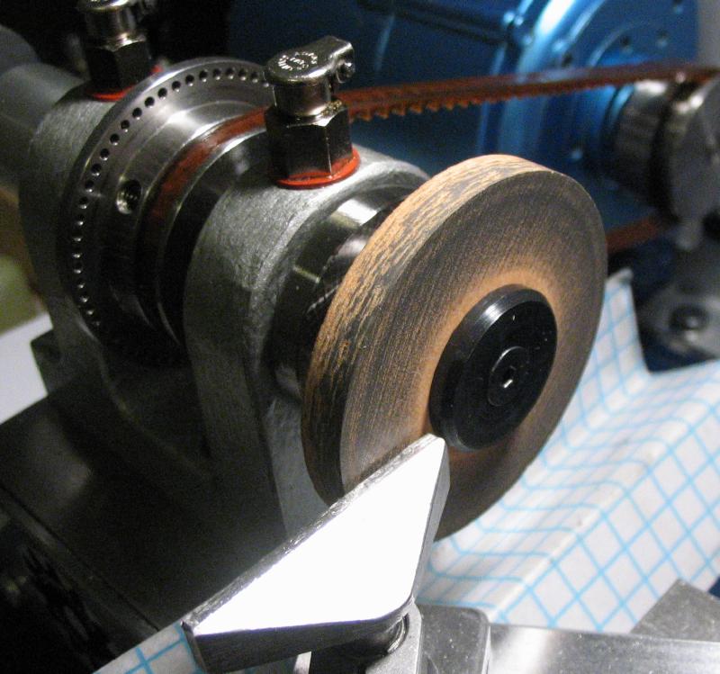
The cutting faces were ground using a Norton 38A400 wheel and the T-rest for support. I don't like grinding on the lathe, but this required very little time to form an edge. The other faces were smoothed with India and Arkansas stones. The countersink was hardened in oil and left fully hard for use. The black scale was removed with a stone on the lathe and the cutting faces touched up using the same methods as before. A pilot was made from a short length of 2mm drill rod with the ends chamfered. The pilot was inserted with the aid of a few taps of a small hammer.
|
|
|
|
The countersink was held in a collet and the guide bar setup in the vise on the vertical slide. The bearing hole was located with the pilot of the countersink and with some cutting oil applied, the cutter plunged in.
|
|
A thumb nut was made for adjusting the feedscrew. It was made from 1/2" cold roll steel rod (1018). About 15mm was turned down to 12mm in diameter and then 6mm turned down to about 5.5mm. The corners were chamfered 45 degrees using the compound slide. The rod was spot drilled, drilled 1.7mm for about 15mm, and then reamed 2mm. The hole was countersunk 60 degrees as well.
|
|
|
|
|
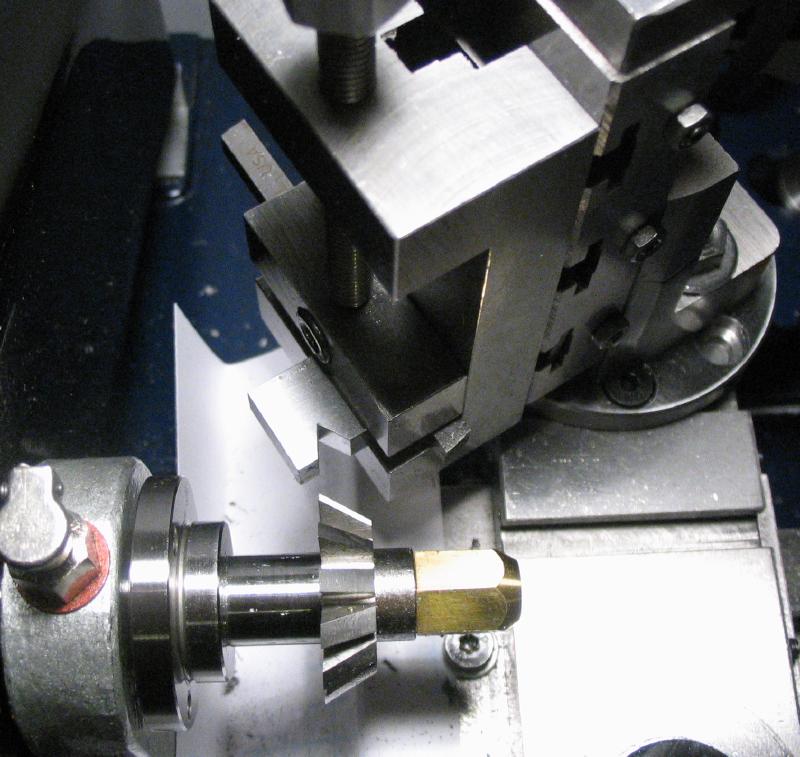
The headstock was locked and the milling spindle installed and brought onto lathe center and centered on the small diameter boss to drill 3/64". The headstock was indexed through 15 steps and grooves milled with a 1/16" ball end mill to a depth of 0.5mm.
|
|
|
|
The work was removed from the chuck and setup in a vice for tapping the small hole #0-80 for the stainless steel set screw shown up above (it need not be stainless steel, of course). The nut could finally be parted off with the total length of about 12mm.
|
|
It was reversed into a collet and the parted side faced and chamfered 45 degrees to match the other side. It was bored open to 5mm diameter for 1.5mm depth to fit a draw-in nut, however, this is unnecessary and perhaps better if left flat. The small hole was countersunk while still mounted on the lathe and the bore opening countersunk by hand.
|
|
|
The draw-in nut was made from 3/8" cold roll steel (12L14) rod. It was turned down to 7mm and a 1.5mm long boss reduced to just under 5mm diameter. The rod was drilled 1.6mm and tapped M2x0.4mm, and a hex shape was formed by milling to a depth of 0.5mm on each of six faces (starting with hex rod would be easier, of course). The nut was parted off with a 2mm thick hex portion and tool marks removed with emery paper.
|
|
|
|
|
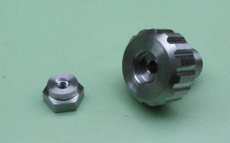
The nut was chamfered 45 degrees to match the knob and take the sharp corners off.
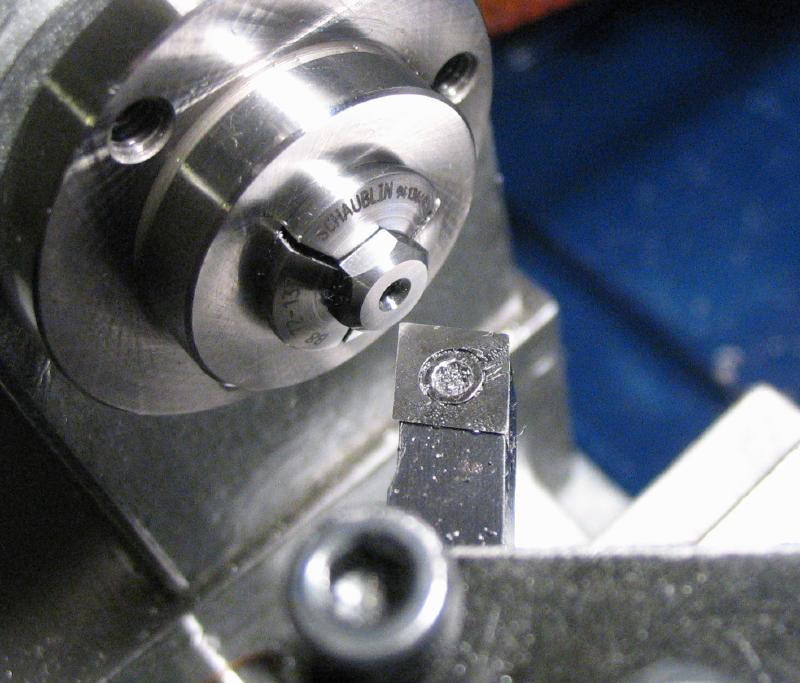
A small center was made from 5mm drill rod. It was turned down to about 4mm or so and then turned with taper of 30 degrees. It was then turned down to just under 2mm diameter. It was then hardened and lightly polished and ready for use.
|
|
|
|
|
|
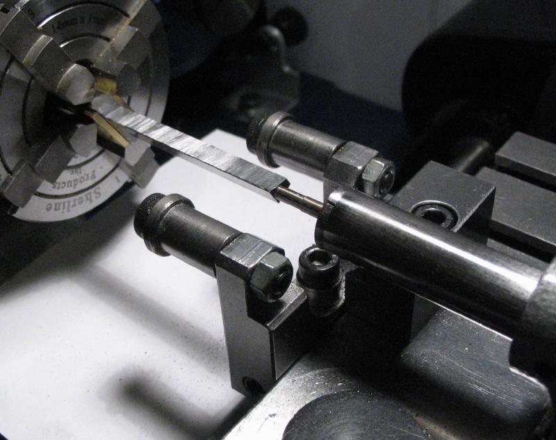
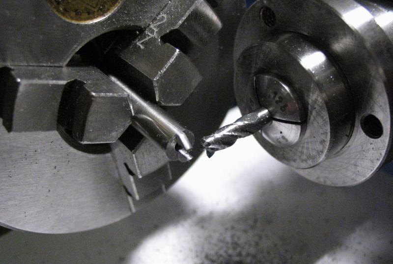
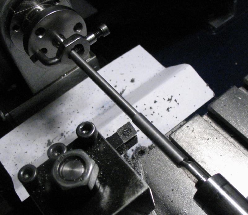
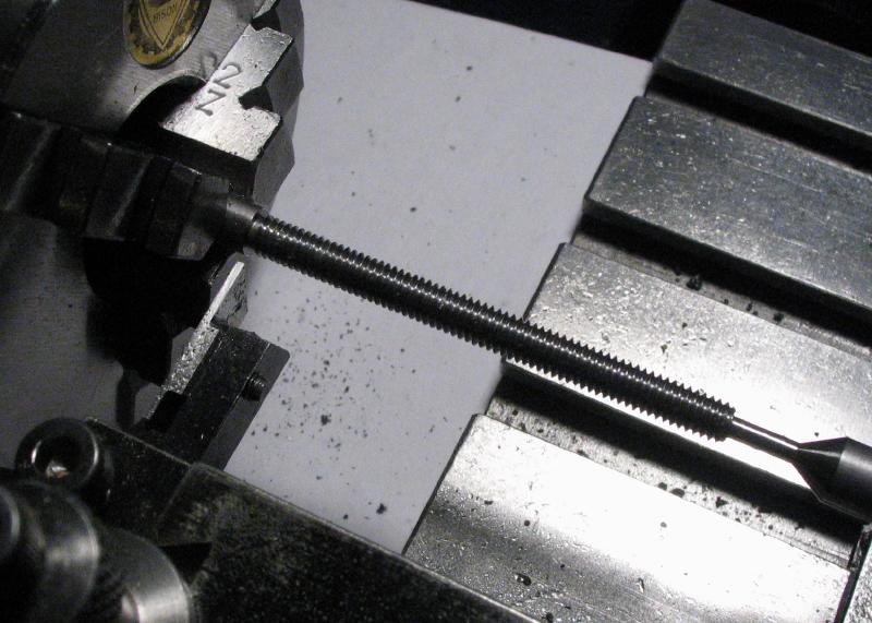
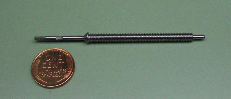
The feed screw was made from 5mm O-1 drill rod. A length was roughly measured and cut off. Each end was faced and center drilled with a #0000 countersink drill, which allows the rod to be mounted between centers. A driving plate with center, a dog attached to the rod, and a half center in the tail stock were used to turn the rod down to 3.98mm for 53mm. The work was reversed to lightly turn other end to make it concentric. The work was reversed back, but swapping the half-center for the small male center made above, and the end turned down to 2mm for about 6mm.
|
|
|
|
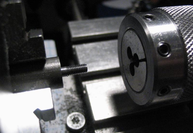
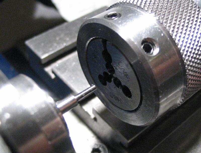
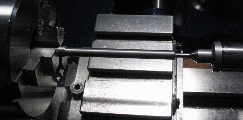
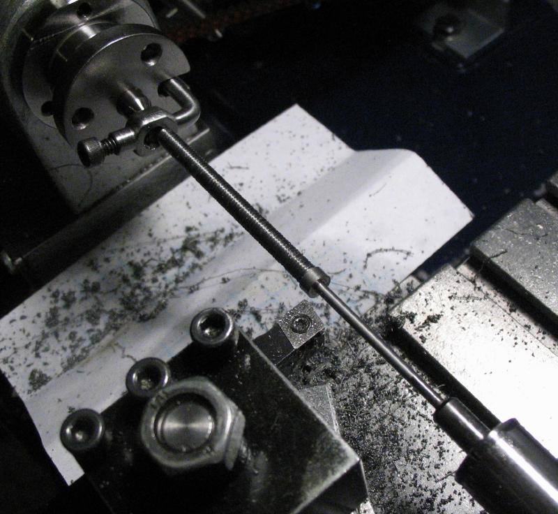
The work was moved to the 3-jaw chuck for threading the rod with a die in the tailstock holder. Since the die does not goes right up to the shoulder, a parting tool was used to turn this area down.
|
|
|
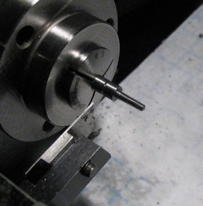
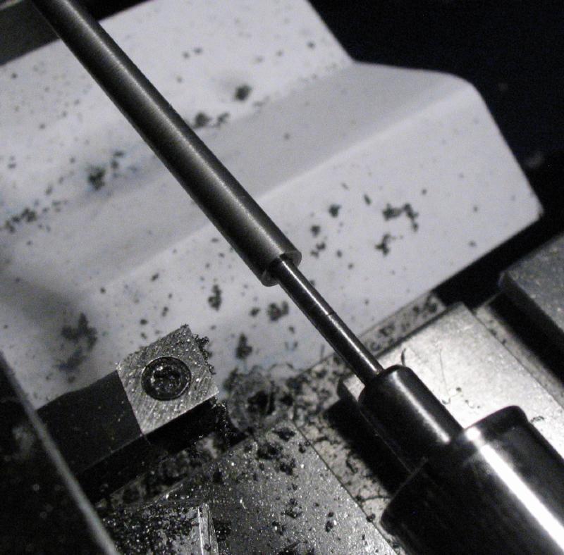
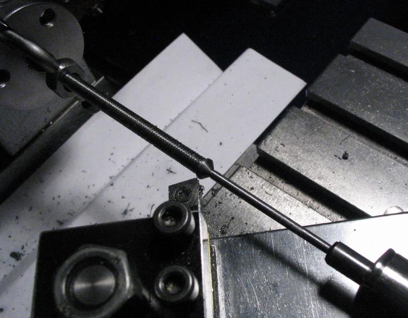
The work was put back between centers to turn the other end down to 2mm, leaving a hub about 2mm in length. The hub was turned with a taper of 45 degrees. I intentionally undercut at the base of the taper for clearance, but the tool dug-in a bit. So it is not perfect looking, but should function as intended.
|
|
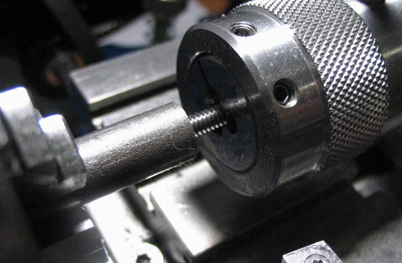
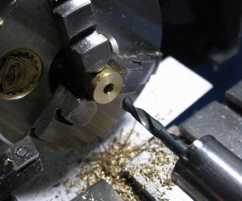
For holding the work during the last couple steps, a threaded arbor was made from a short length of brass rod from the scrap box. It was faced on either side and drilled 3.3mm, and tapped M4x0.7. The hole was countersunk and the feed screw installed. As long as the brass rod is left in the chuck after making it, the threaded hole should remain reasonably on center.
|
|
|
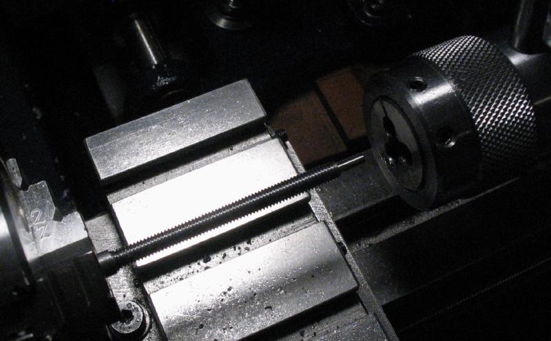
An endmill was used to form a flat for the set screw, and the end of the rod threaded M2x0.4. The threading step is not shown since the die locked up and unscrewed the work from the arbor rather than backing off the thread, once it was freed, enough thread was already established that the work was disassembled without a photo. The ends of the feedscrew rod were rounded over with a cup bur.
|
|
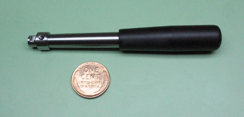
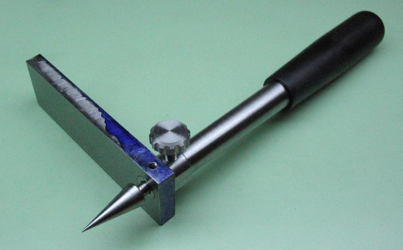
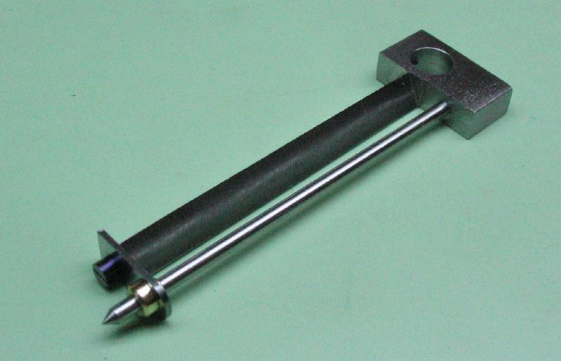
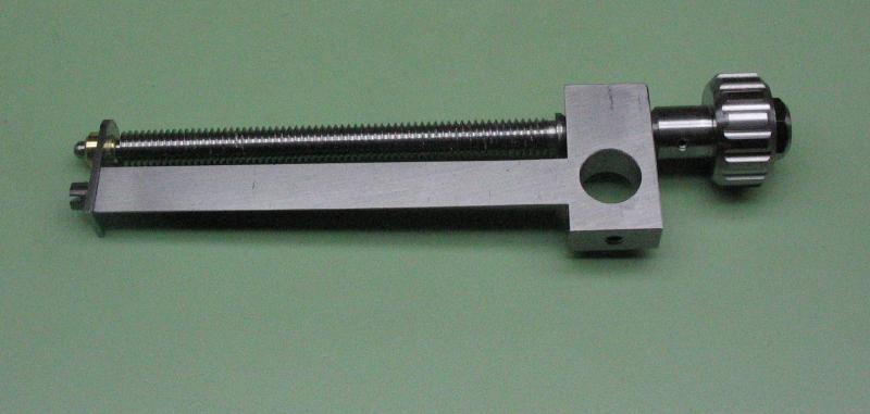
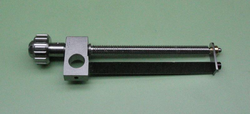
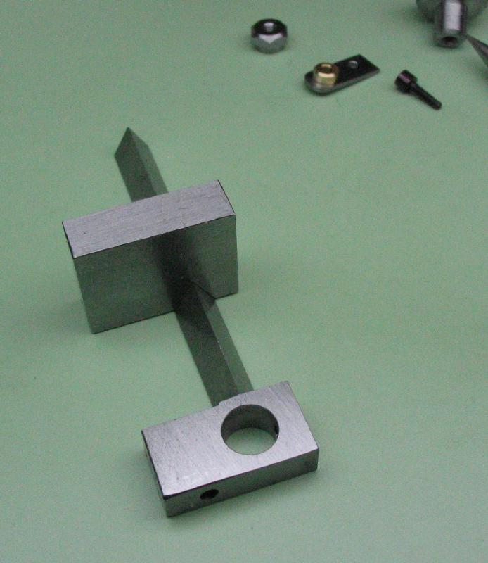
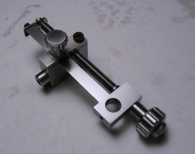
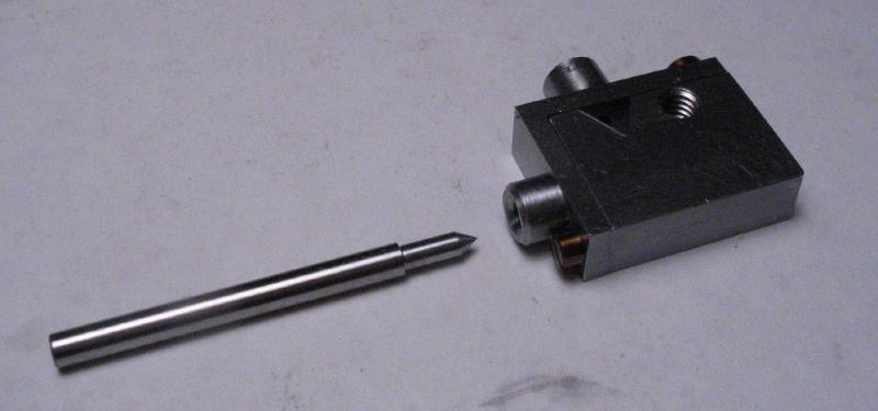
All the components were assembled for a test fit, and start planning the rest of the tool.
|
|
|
|
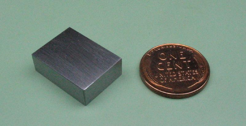
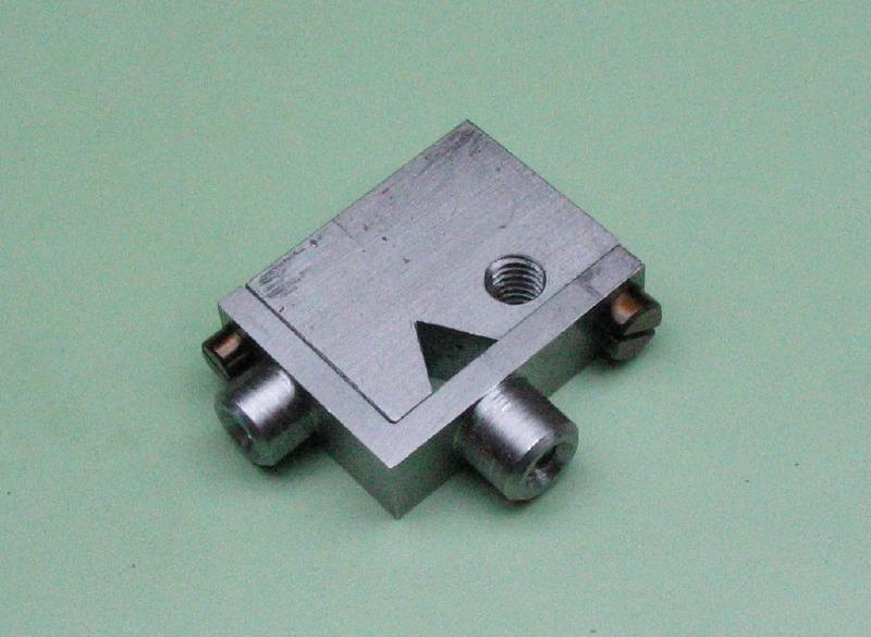
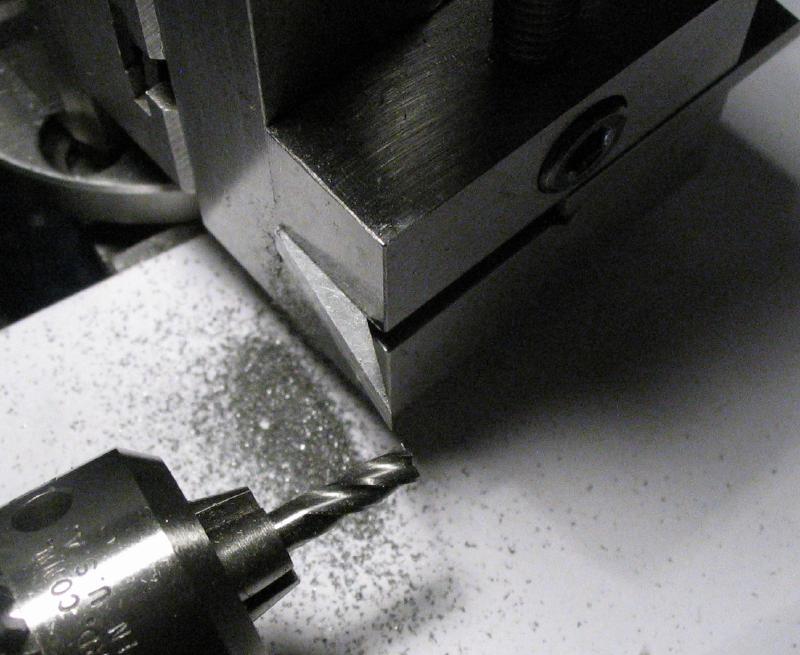
The remaining components of the compass are a scribe and its holder that fits the guide and feed screw. This carriage would likely be best made as one piece, but would require forming an accurate hole that fits the triangular guide. Instead, I decided to try a two-piece construction and started with a piece of 1/4" cold roll steel bar (type 1018) that was about 3/4" wide (19mm) and 14mm in length after sawing off and milling the edges to square things up, and the faces smoothed on 400 grit emery paper. A 60 degree vee slot was milled using a PP Thornton 60 degree ratchet cutter. To reduce the burden on this cutter, the vee was brought almost to final size by cutting out with a slotting saw.
|
|
|
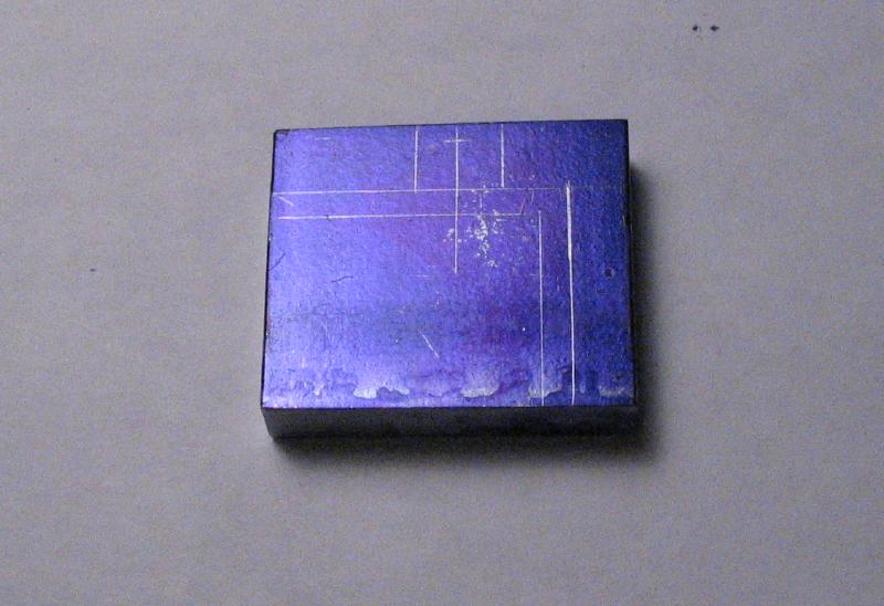
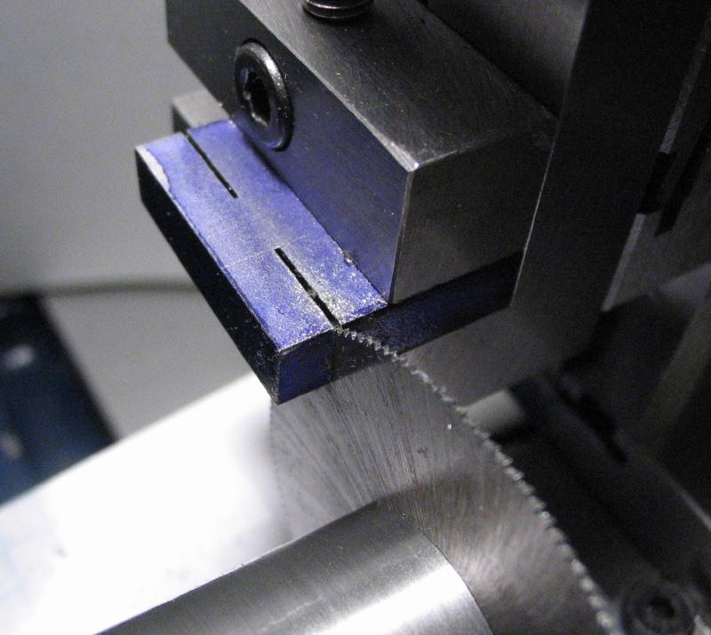
Another piece of 1/4" steel bar was sawed out and milled to square the edges. The locations for one of the locking screws was sawed out using a slotting saw.
|
|
|
The work was moved to the 4-jaw chuck and centered on the screw location. It was turned round and to about 6mm diameter, and then drilled and tapped M3x0.5. The top face was turned true and the corners chamfered and countersunk.
|
|
|
|
|
The same process was repeated for the second position, however was threaded #4-40, which is about 2.84mm in diameter.
|
|
|
|
|
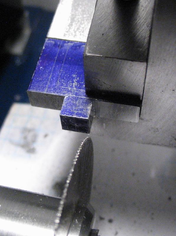
The work was then sawed out to fit the lower part of the carriage made above. The inside faces of the work were cleaned up with emery paper that was taped to a steel block to help keep the faces square.
|
|
|
The location for one of the screws, to fix the upper and lower halves of the carriage together, was laid out and center punched. A piece of 1/4" brass bar that was milled flat on both ends and is slightly longer in length of the upper piece was used as a sacrificial surface to drill the hole in the upper piece. The hole was countersunk on the inner face to remove burs and then mounted back in the vise to start the hole in the lower piece of the carriage. The upper piece was removed and hole continued to final depth. The hole in the upper piece was enlarged to clear the screw (2mm), and the lower piece then tapped M2. This process was likely more complicated than need be.
Spot drilled and drilled 1.6mm
|
Start drill in lower portion
|
Drill lower portion
|
Open hole in upper piece
|
Tap lower piece
|
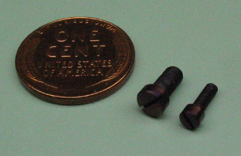
Two screws were made to fix the two parts together. One screw is M2x0.4mm with about a 1/8" diameter head, and the other M3x0.5mm with a 4.5mm diameter head. The process is the same as above, so only a few photos were taken. The screws were made from O-1 drill rod and hardened and tempered.
|
|
|
|
|
The position for the feed screw was determined using the same method as with the bearing bracket made above. The work was assembled and the 2mm pointed rod inserted into the feed screw hole to make a mark on the carriage piece. The mark was then center punched and drilled 3.3mm to be tapped M4x0.7mm.
|
|
|
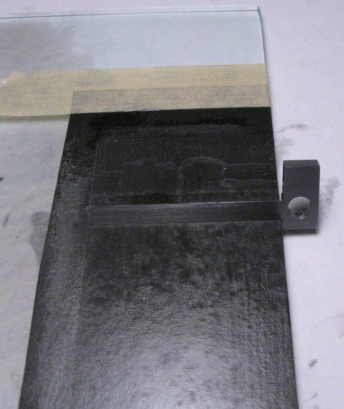
The second screw position was drilled 2.5mm, the hole in the upper piece enlarged to 3mm, and the lower piece tapped M3. The carriage components were assembled and the guide bar finished to fit. There were several high spots, where the carriage binds on the guide bar. The faces of the bar were smoothed on emery paper that is fixed on glass. The feed screw assembly was installed and the final dimensions of the bearing bracket were determined and it was brought to size with files.
I was delighted that the screw feed and carriage worked as well as it did, but it was at this time that I realized a left-handed thread would be preferable. The carriage moves outwards with a counterclockwise turn of the knob, which is counter-intuitive, but will have to do!
|
|
|
|
|
|
|
Two thumb screws are needed for the carriage (one is shown in the photo above). They were made in the same manner as the previous thumb screw for locking the cone center. One screw is to lock the position on the guide bar and is M3x0.5mm. The second screw is #4-40 and to lock the position of scribe, which is yet to be made.
|
|
|
|
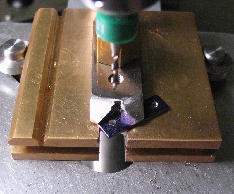
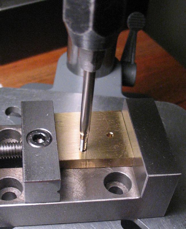
The position for the scribe slot was transferred to the lower piece with a length of drill rod that was turned to fit the threaded hole and with a 60 degree point. The center mark was used to then mill a 1/8" slot with an endmill.
|
|
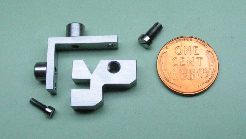
Some of the excess material was removed from the lower piece of the carriage by drilling, sawing and milling. The parts were then cleaned up with 800 grit emery paper.
|
|
|
|
|
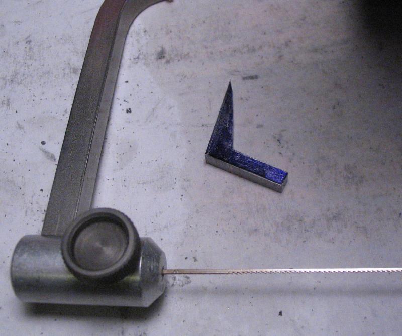
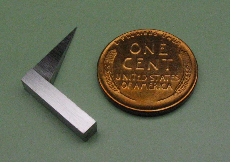
The scribe was started from 1/8" thick oil-hardening steel plate. A piece was sawed out and milled to roughly square the edges, and was about 3/4" x 1" or so in size. The work was laid out and the bulk removed by sawing, followed by milling to straighten things out.
|
|
|
|
|
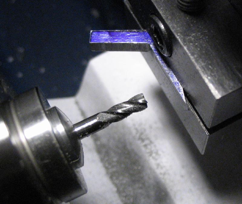
The scribe was tried in the tool and found that the angle on the front face did not exactly match the taper of the cone center. It was mounted back in the vertical slide and the offset angle set using the cone center itself, which was mounted in the tailstock. The face was then milled again.
|
|
|
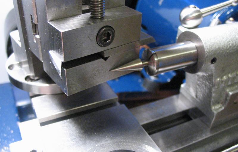
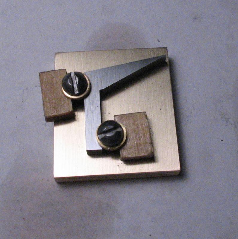
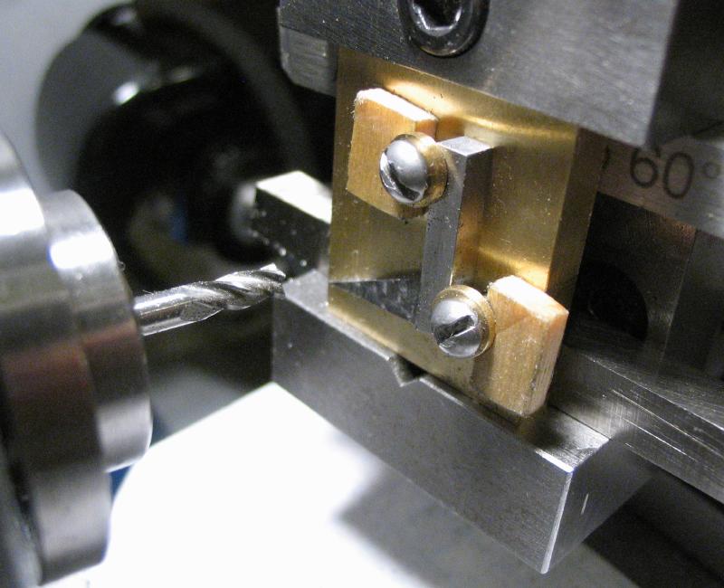
A piece of 3/16" brass plate was milled on opposing edges to make them parallel and then drilled and tapped #4-40 to fit two screws that will clamp the scribe down for milling its tip to a point. The screws have brass washers and pieces of 1/8" thick wood to counter the clamping pressure. The assembly was mounted in the machine vise and was rotated about 9.5 degrees, although my calculations appear to be off and a greater angle would be preferred.
|
|
|
|
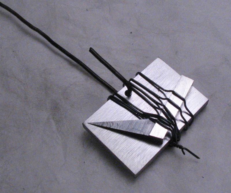
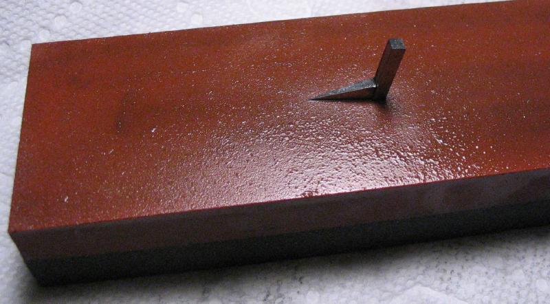
In an attempt to prevent the scribe from warping (it did slightly anyway), the scribe was hardened by first fastening it to a piece of the same steel plate it was made from. After hardening it was tempered to about a straw/yellow color and the faces ground on an India bench stone.
|
|
|
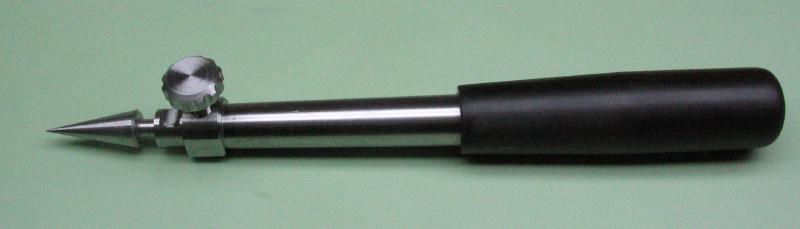
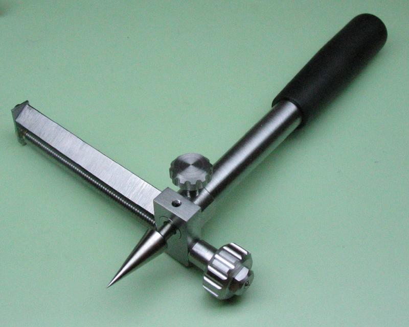
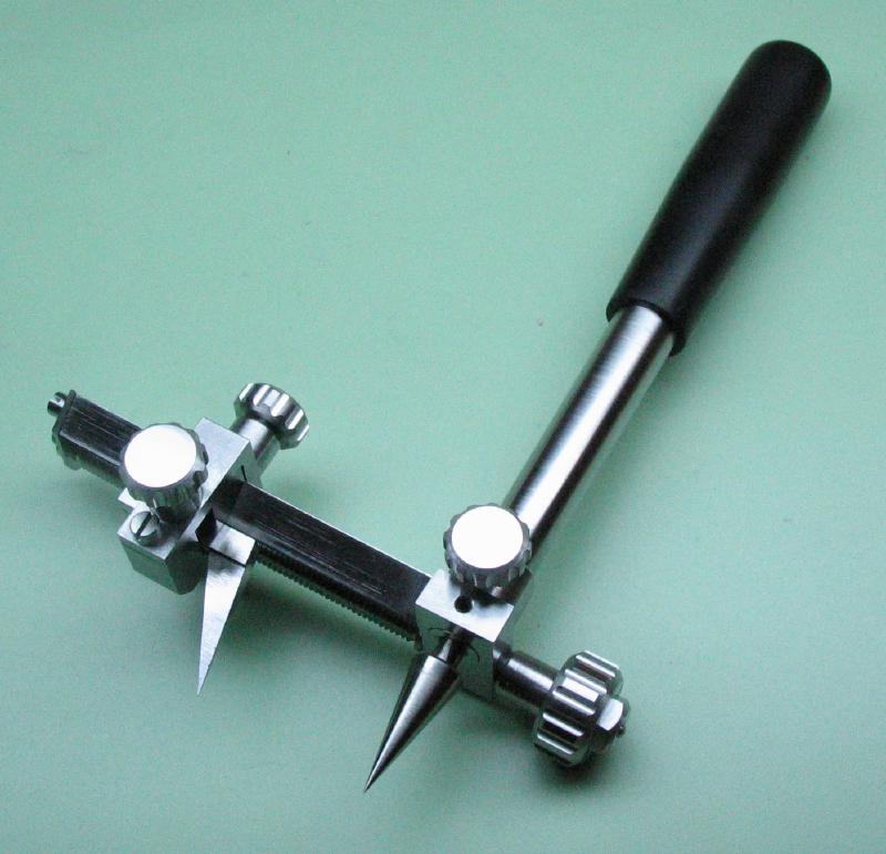
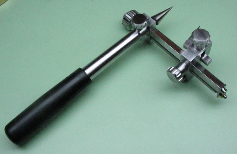
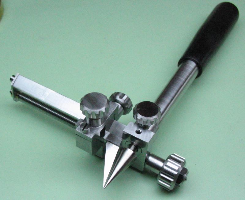
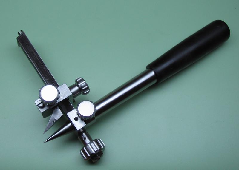
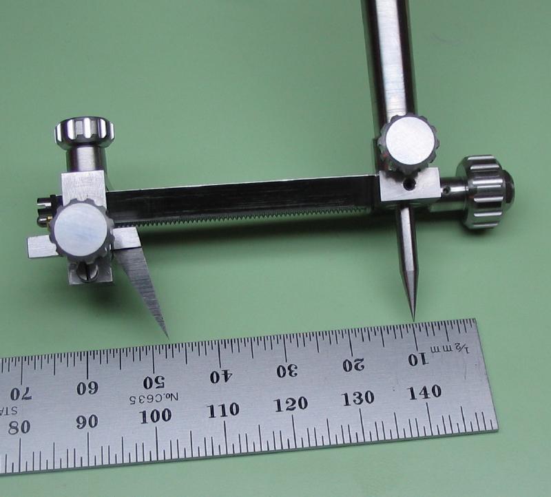
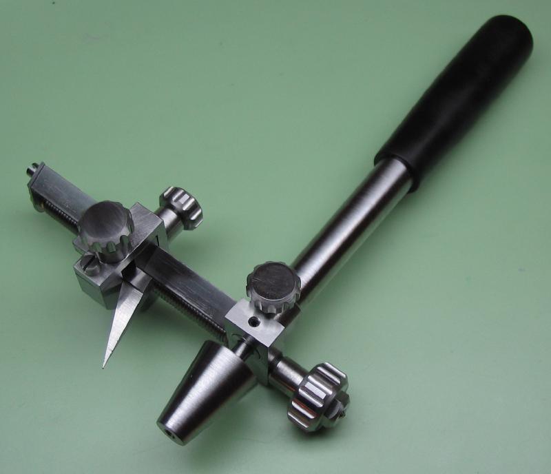
The components were washed in naptha and assembled with a drop of Starrett 'Tool & Instrument Oil' applied to moving points.
|
|
|
|
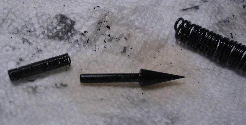
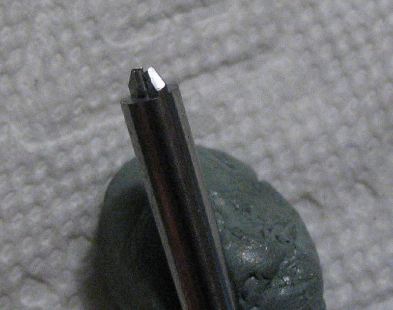
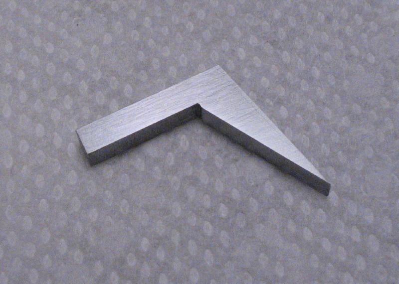
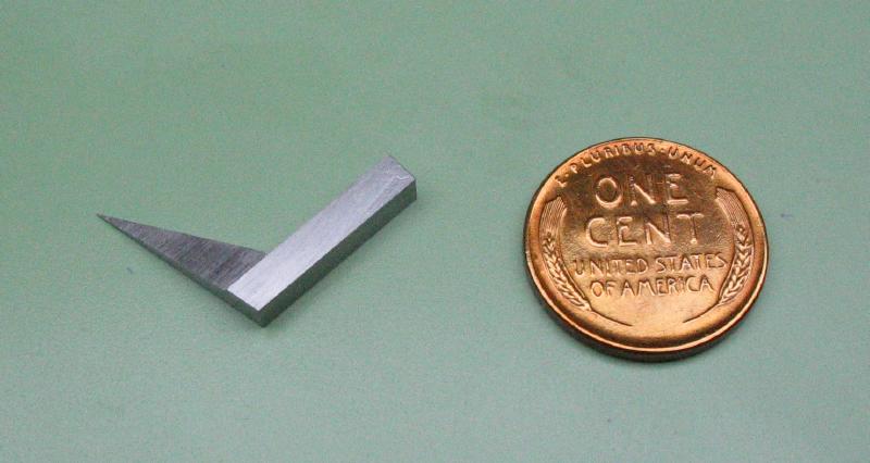
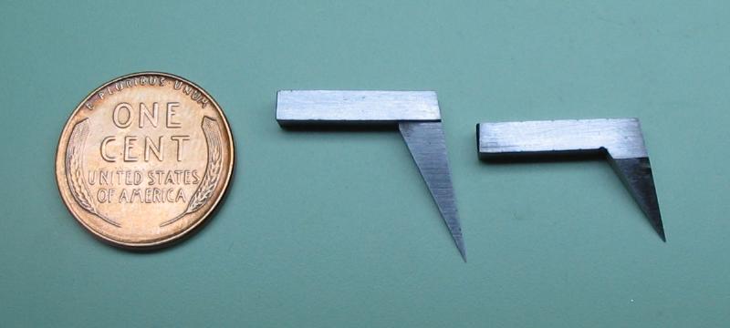
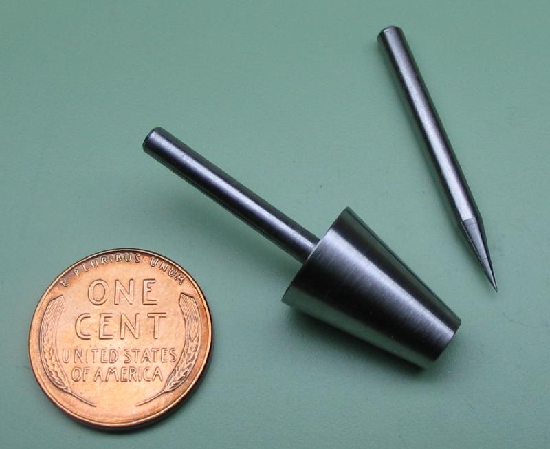
The scribe point made above is a bit longer than originally intended and a another attempt was made, and this one ended up a little shorter than intended.
|
|
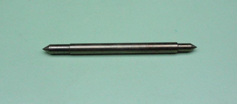
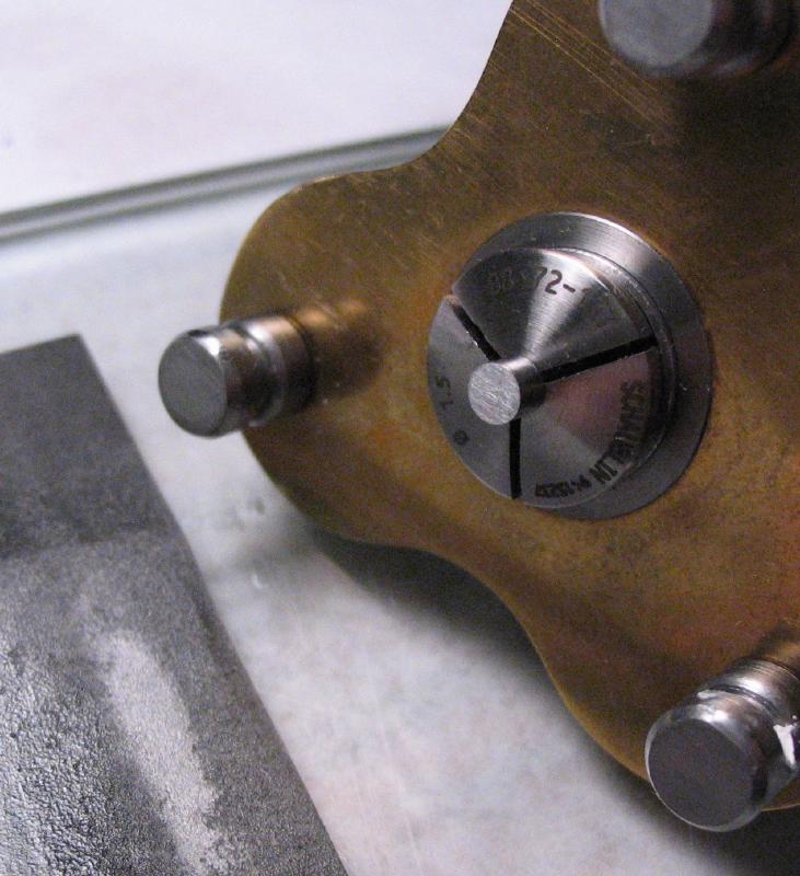
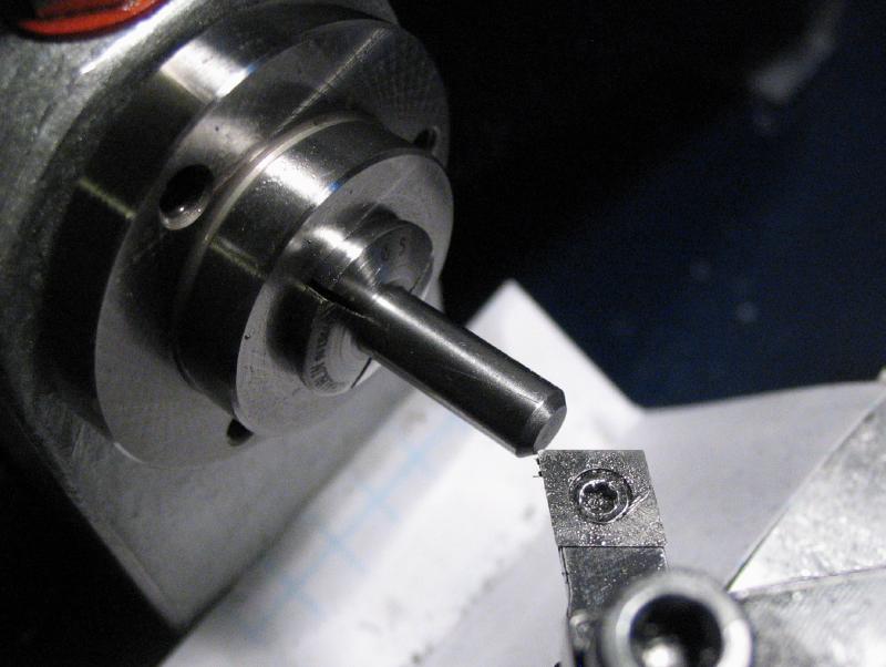
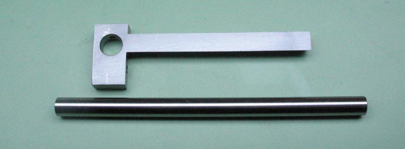
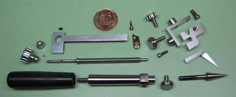
A bull-nose style center was made as well as one from just a length of 3mm drill rod. Both have a matching 10 degree taper. The bull-nose is useful for larger diameter holes and the small center is primarily intended for setting the desired radius on compass.
|
|