Fixed Fourth Wheel
The fourth wheel of this watch is fixed to the mainplate, as is the case in tourbillon watches. Instead of the conventional gear train, the third wheel drives a separate fourth pinion, which is attached to the tourbillon carriage (it is therefore called the carriage pinion). The carriage contains the balance and escapement, which rotates concentrically to the stationary fourth wheel by interaction with the escape pinion.
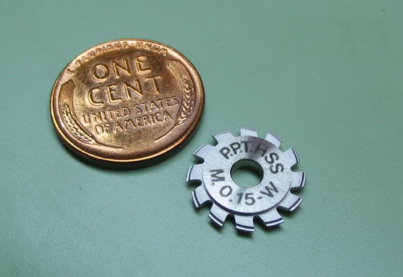
The execution of the fourth wheel is therefore a bit different than the center or third wheels. The module can be calculated from the available space as approximately 0.15. PP Thornton currently produces wheel and pinion cutters in this module. Complete dimensions and calculations are provided in the PDF document below.
I started with 1/2" (12.7mm) 360 Brass rod. Since the critical dimensions of the wheel can be done in 'one-chucking' it can be made using the three jaw chuck. The rod is faced and a portion turned to the full wheel diameter (12.375mm). The base portion is turned which ensures it will be concentric with the teeth. A portion behind the tooth flange is turned to give clearance for the wheel cutter. The 80 teeth are milled, using the same setup as previously used for the center and third wheels, however using a 0.15M wheel cutter. The rod is center drilled and drilled undersized (4mm) for the fourth/carriage pinion opening. It is then bored to full diameter (6mm). The positions for the retaining screws are drilled with the 0.7mm clearance drill. It can then be easily parted off from the rod. The wheel is then mounted in a step chuck by its base. I used a 3/4" pot chuck blank from Sherline, and bored a recess to fit the fourth wheel base. Since the pot chuck would not have clearance for the boring cutter, I bored the pinion opening prior to parting off from the rod (this deviates from Daniels' technique). While in the step chuck the wheel is faced to the correct tooth flange thickness and the center recess is bored for clearance of the carriage pinion collar and retaining screws.
| fourth_wheel.pdf |
Rod faced with a round nose cutting bit
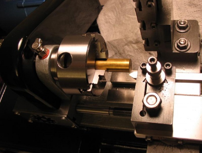
Turned to full tooth diameter with right hand cutting tool

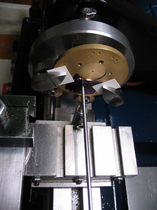
Recess turned and lathe setup for milling teeth
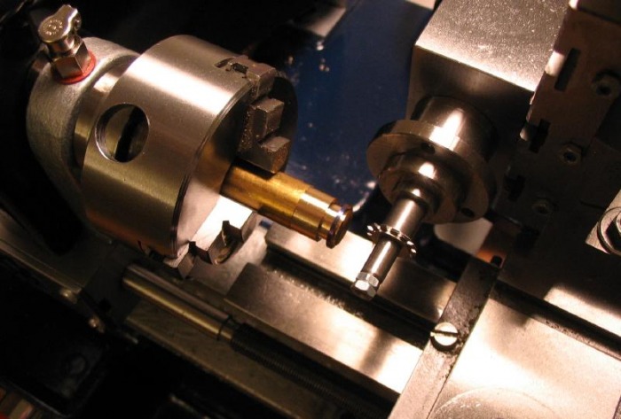
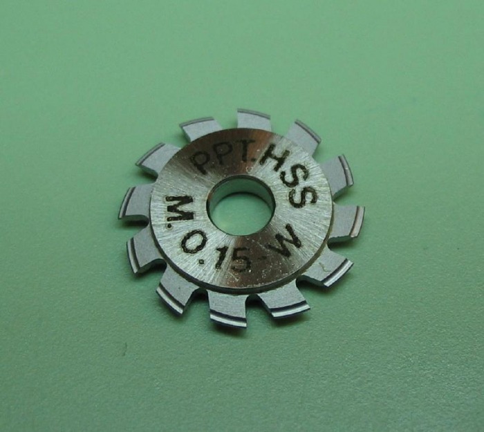
Photo during the milling process
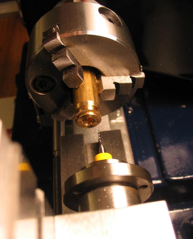
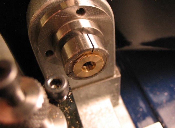
Milling complete, and center bore drilled undersize
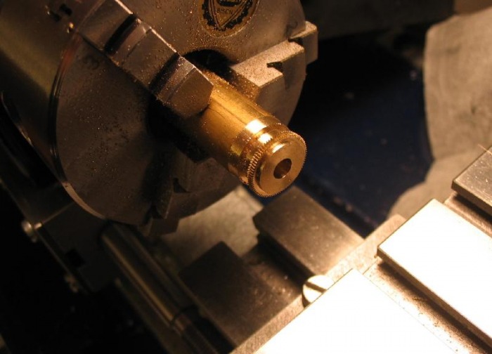
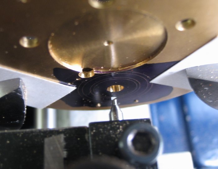
Center boring complete

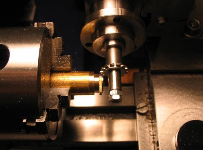
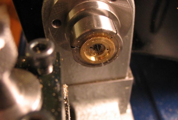
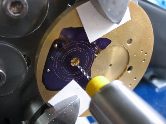
Screw positions located and drilled using the mill spindle
Wheel gripped by base in a pot chuck and tooth flange faced to final thickness
Recess bored to final dimensions
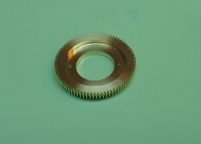
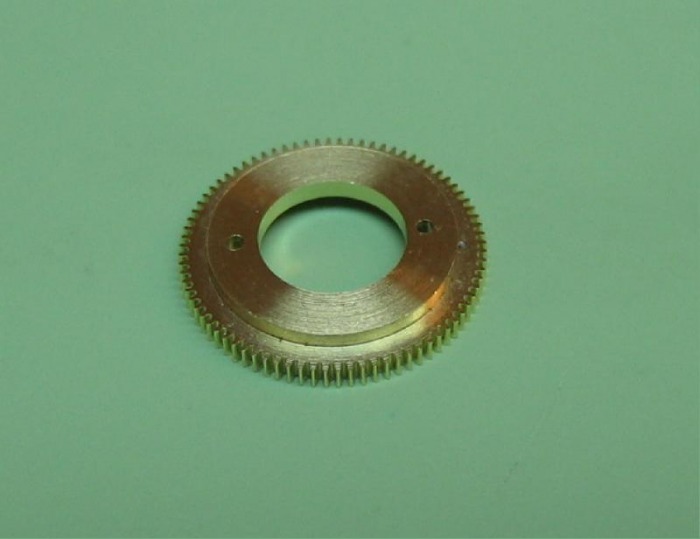
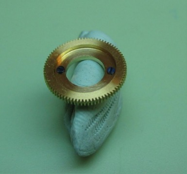
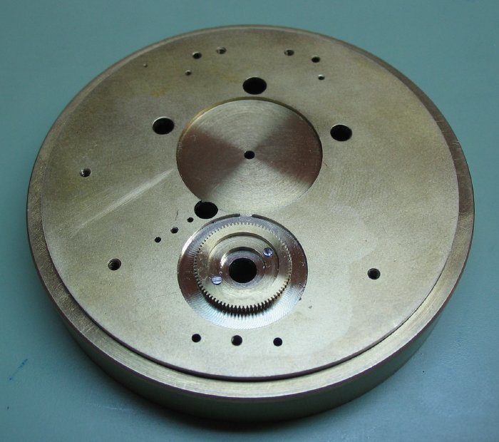
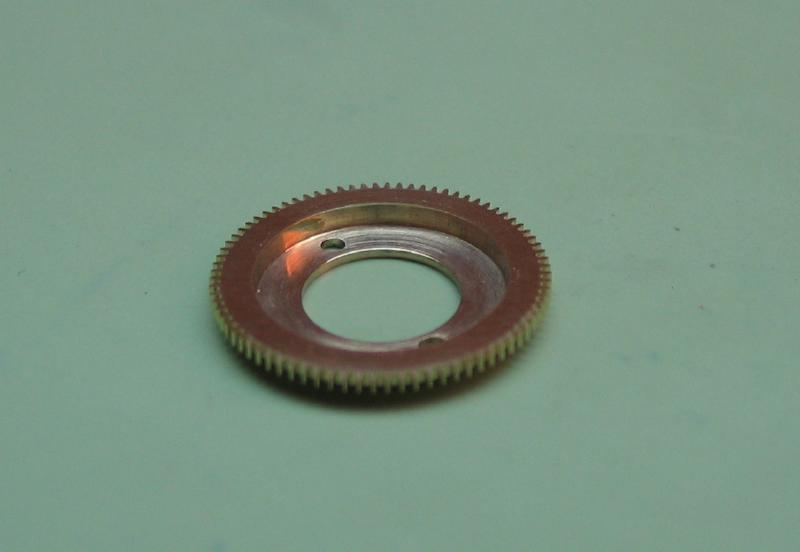
Completed fouth wheel (top & bottom views)
Simple cheese head screws are made to retain the fourth wheel to the mainplate. The screws are 0.7mm and have heads 1.2mm in diameter and 0.25mm thick.
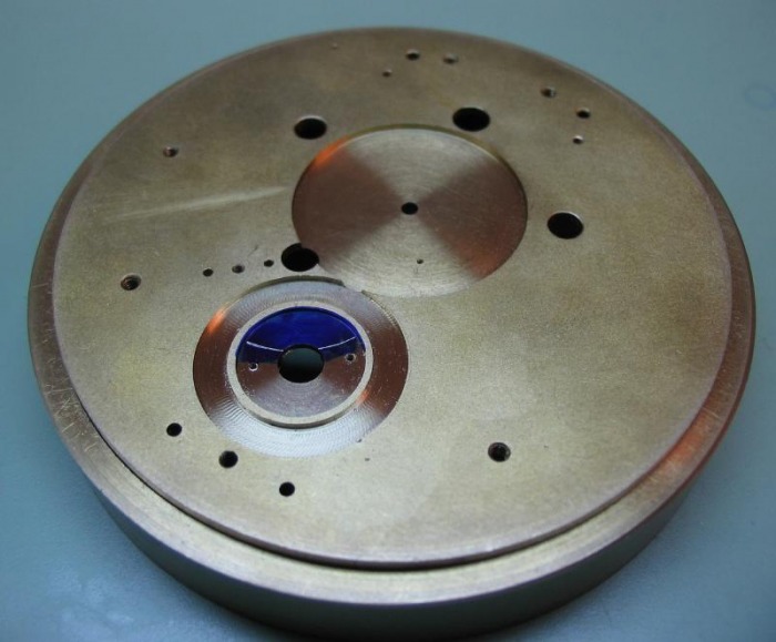
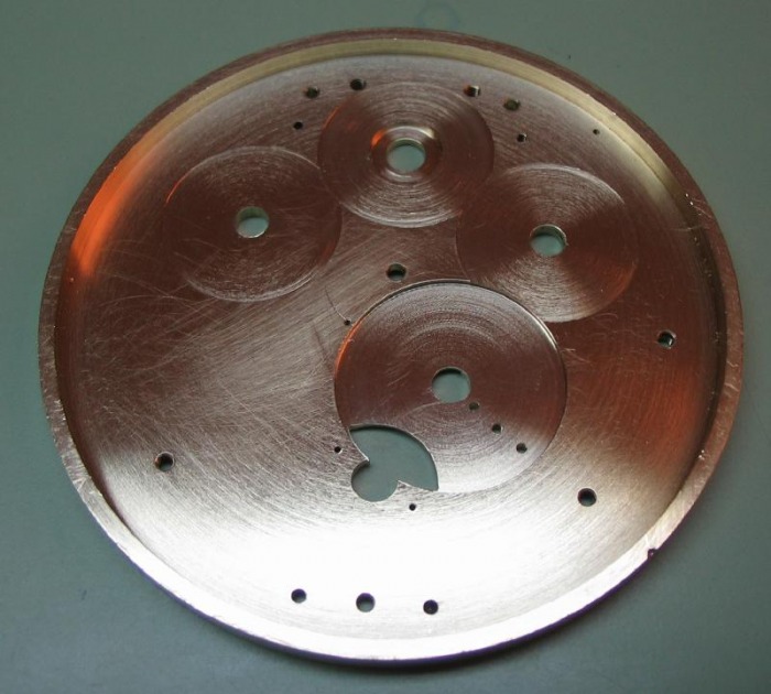
Locating the Fixed Fourth Wheel
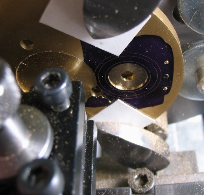
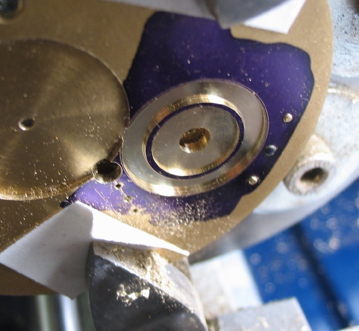
The mainplate is bored to accept the base of the fourth wheel (10mm). This recess is bored to a depth of 0.4mm.
The radius of the cutter is increased, and the recess for the escape pinion potence is made. This boring is made to touch the center wheel recess and to the same depth as well. By using a left hand boring cutter the circular wall which retains the fourth wheel can be squared. Daniels describes this process in about one sentence, mine is not much longer, but I will mention that it was a tricky operation, great care must be taken while boring the escape potence recess, slow and shallow cuts were made to minimize chatter and risking heavy stress on the cutter.

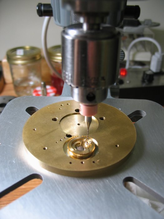
The mainplate can then be removed from the faceplate and the screw positions determined, drilled and tapped 0.7mm. The positions should be outside of the third wheel diameter, as the mainplate is quite thin within this area. I drilled and tapped one position, and inserted the screw, and then drilled and tapped the second to ensure the location is correct. Although not stated, it is apparent from the photos in "Watchmaking" that the portion of mainplate which is intersected by the areas of the third wheel and the fourth wheel locating recess is sawn out. This allows one to see the third wheel in a small window, driving the carriage pinion.
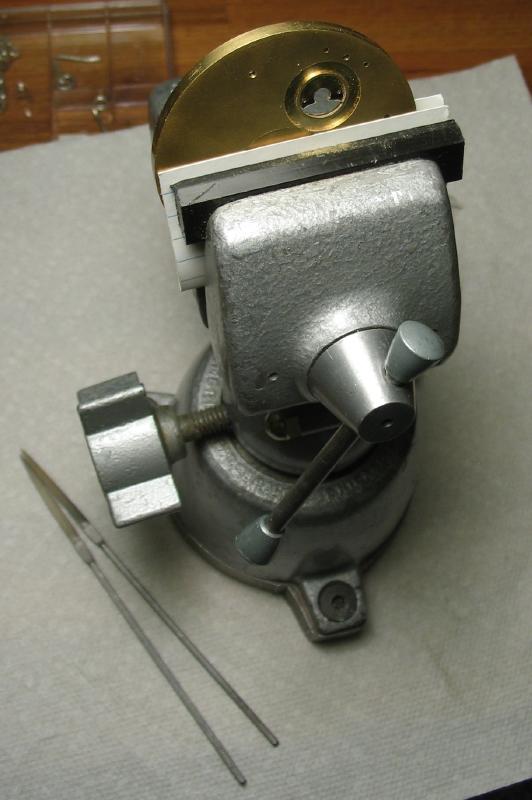
The cutout follows the wall diameter and the third wheel recess diameter. A scribe was made as a starting point.
The space was cutout with the piercing saw (6/0 blade), and then setup in the Palmgren vise with protection. The space was filed to shape using No.4 escapement crossing file followed by a No.6 file.
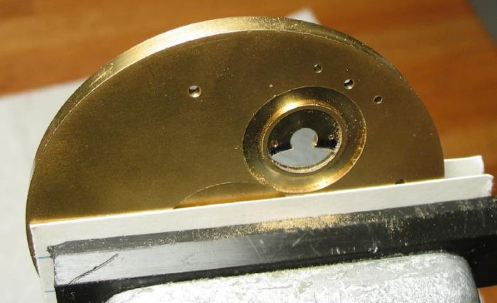
Finished
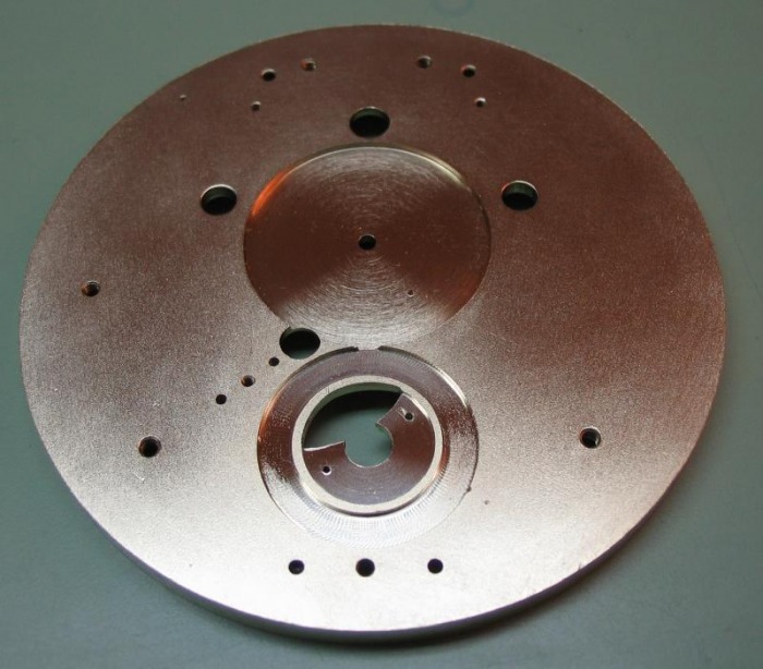
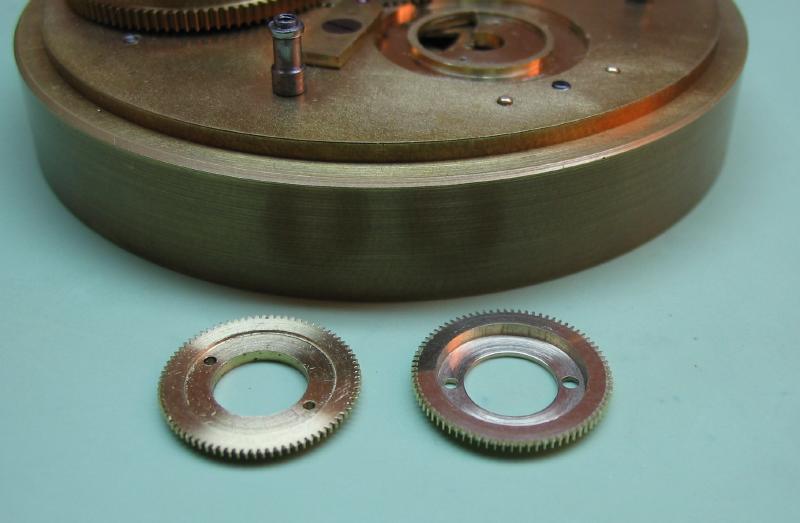
Just for the record....
The original is on the left, of course...
 |
 |
