Filing Machine
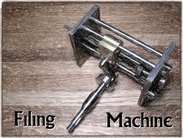
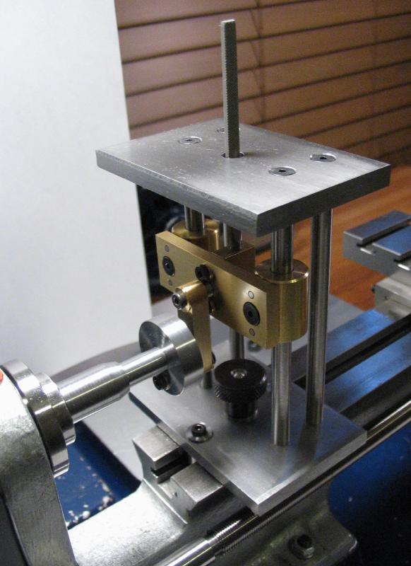
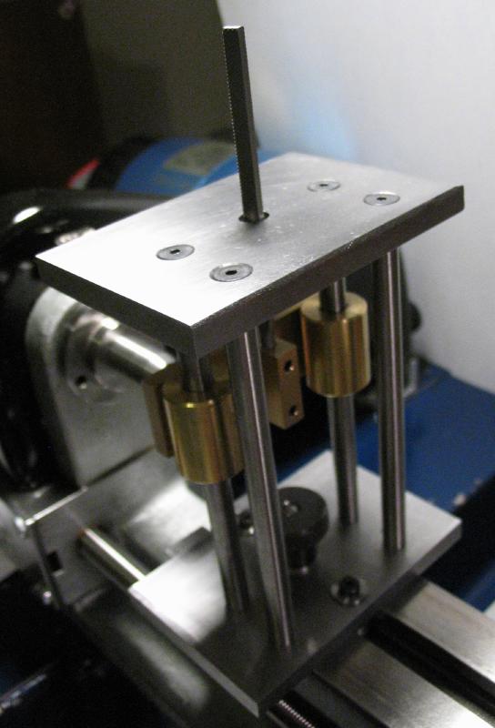
In Louis and Samuel Levin's book, titled "Practical Benchwork for Horologists," they provide construction details for a filing machine attachment to a watchmaker's lathe. The machine consists of two plates separated by four posts, the lower plate mounts atop the lathe bed and the upper plate acts as the work table with a reciprocating file in a center hole. The file is held on a crossbar that is attached to guide bushings that use two of the posts for their alignment. The reciprocating motion of the crossbar assembly is provided by a connecting rod and crank that is mounted in the lathe headstock. The technical drawing in the book is reduced in scale due to the dimensions of the book itself, so it was scanned and enlarged to about actual size for printing to use at the bench and happened to conveniently fit on a single sheet of paper. I gathered up most of the needed materials before getting started, and my inventory is below, although I am sure I have not thought of everything.
In Louis and Samuel Levin's book, titled "Practical Benchwork for Horologists," they provide construction details for a filing machine attachment to a watchmaker's lathe. The machine consists of two plates separated by four posts, the lower plate mounts atop the lathe bed and the upper plate acts as the work table with a reciprocating file in a center hole. The file is held on a crossbar that is attached to guide bushings that use two of the posts for their alignment. The reciprocating motion of the crossbar assembly is provided by a connecting rod and crank that is mounted in the lathe headstock. The technical drawing in the book is reduced in scale due to the dimensions of the book itself, so it was scanned and enlarged to about actual size for printing to use at the bench and happened to conveniently fit on a single sheet of paper. I gathered up most of the needed materials before getting started, and my inventory is below, although I am sure I have not thought of everything.
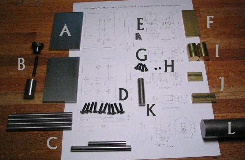
A - 1/4" x 2" x 6" low-carbon "cold-worked" steel, sawed into two pieces for the lower plate and upper plate.
B - A scrap piece of 16mm drill rod for making a T-nut to fit the lathe bed, a length of M5x0.8 threaded rod, and a stock M5 steel thumb nut.
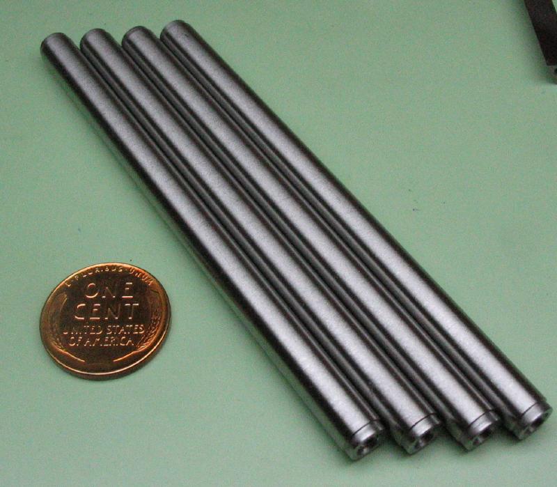
C - 1/4" O-1 drill rod for the posts, sawed off oversized for producing a final length of 3-5/8". Plus a couple random lengths of 1/4" drill rod for the drive pins.
D - Ten (a few more will be needed), #6-32, 82 degree countersunk, flat-head screws with hex drive (they are 5/8" length, although some of these may need to the shortened).
E - Four, #6/0 steel taper pins, 1/2" length
F - 3/16" thick brass plate for the cross bar, happens to be scrap from sawing out the mainplate of the telegraph key, about 3/4" wide and sawed off slightly oversized for producing a final length of 2-1/8".
G - Four (may need a couple more of these as well), M3x0.5 low profile socket head screws in 10 mm length for attaching the file holder to the cross bar and for securing the connecting rod to the drive pins.
H - Two, M3x0.5 Buckley QC brass tipped set screws in 3mm length (tip adds 0.8mm) for locking the file in place.
I - Two, 5/8" diameter brass rods, about 1 inch in length (type 360) for the guide bushings.
J - Two lengths of 1/4" x 1/2" brass bar (type 360), for the file holder and the connecting rod.
K - A length of 3/8" steel rod (12L14) for the T-slot alignment pins.
L - 1" Steel rod for the crank, but I was still deciding on the exact arrangement to use.
B - A scrap piece of 16mm drill rod for making a T-nut to fit the lathe bed, a length of M5x0.8 threaded rod, and a stock M5 steel thumb nut.
C - 1/4" O-1 drill rod for the posts, sawed off oversized for producing a final length of 3-5/8". Plus a couple random lengths of 1/4" drill rod for the drive pins.
D - Ten (a few more will be needed), #6-32, 82 degree countersunk, flat-head screws with hex drive (they are 5/8" length, although some of these may need to the shortened).
E - Four, #6/0 steel taper pins, 1/2" length
F - 3/16" thick brass plate for the cross bar, happens to be scrap from sawing out the mainplate of the telegraph key, about 3/4" wide and sawed off slightly oversized for producing a final length of 2-1/8".
G - Four (may need a couple more of these as well), M3x0.5 low profile socket head screws in 10 mm length for attaching the file holder to the cross bar and for securing the connecting rod to the drive pins.
H - Two, M3x0.5 Buckley QC brass tipped set screws in 3mm length (tip adds 0.8mm) for locking the file in place.
I - Two, 5/8" diameter brass rods, about 1 inch in length (type 360) for the guide bushings.
J - Two lengths of 1/4" x 1/2" brass bar (type 360), for the file holder and the connecting rod.
K - A length of 3/8" steel rod (12L14) for the T-slot alignment pins.
L - 1" Steel rod for the crank, but I was still deciding on the exact arrangement to use.
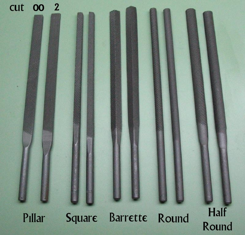
The tool uses "machine files," and in this case with 1/8" round shanks. This type of file has a parallel cutting surface and cuts on the pull (i.e. down) stroke, which is the opposite of a handheld file. Unfortunately, this type of file appears to no longer be manufactured, but can still be found new, as old stock. These files were made in the usual shapes (e.g., pillar, round, half-round, barrette, square, etc.), and limited to two grades of coarseness, Swiss cut 00 and 2. My collection of machine files is shown below and includes the shapes noted and in both coarse and fine cuts.
The plates were started first. As noted above, the upper and lower plate were started from a 6" length of 1/4" x 2" cold roll steel. This was sawed roughly in half and the edges cleaned up by filing. The edges of the stock are deformed from having presumably been sheared from plate. Since the stock is essentially in its final dimensions, the edges were cleaned up with a file, but will not be perfect, however, this should not be a problem as far as functionality.
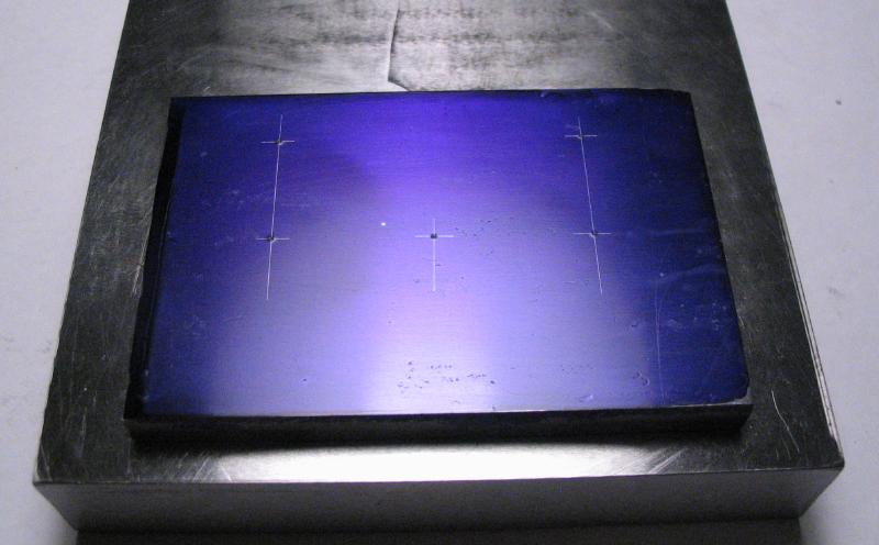
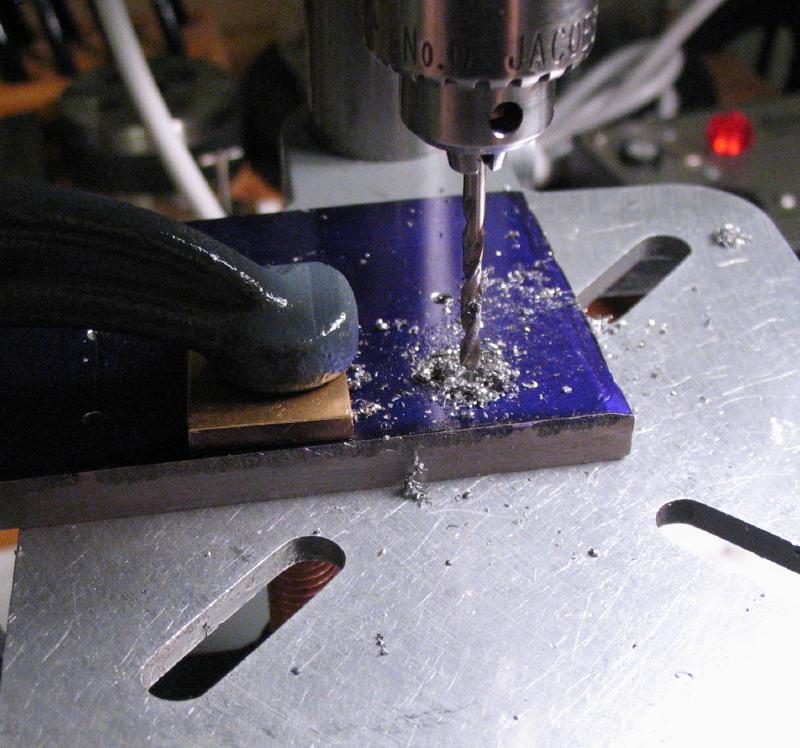
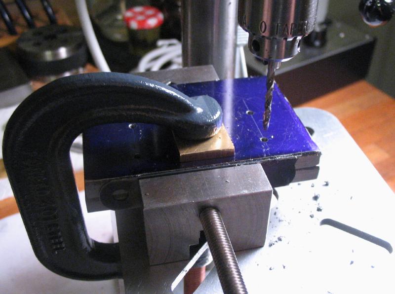
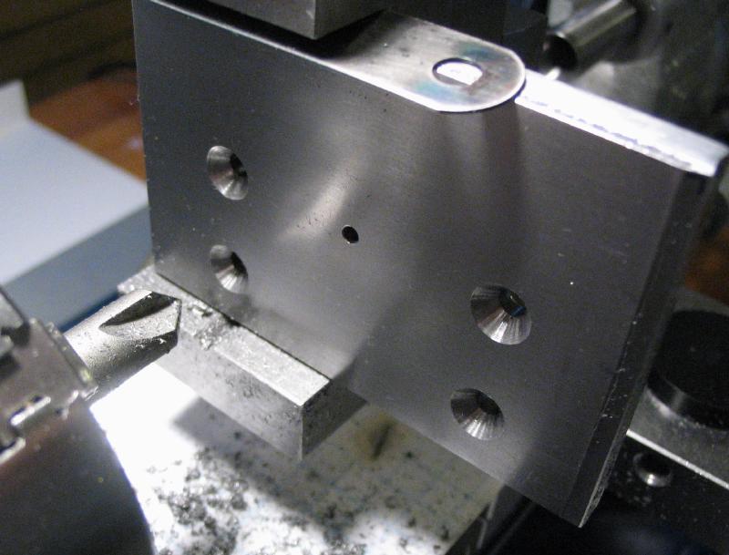
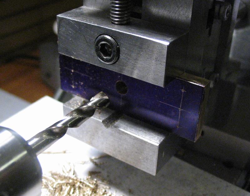
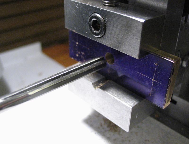
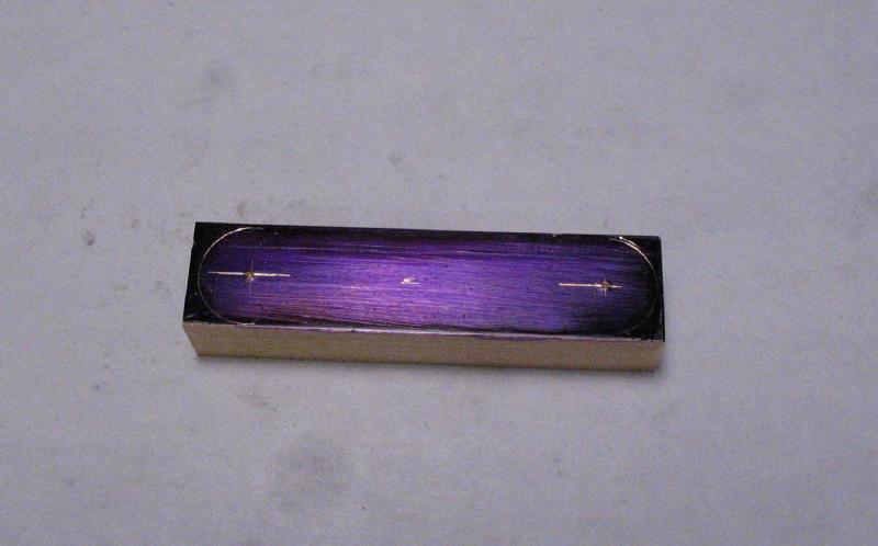
The positions for the posts and the file hole were laid out on the upper plate and center punched. The positions were drilled through with a #43 drill. The upper and lower plate are stacked and mounted together in a vise for drilling the positions in the lower plate.
|
|
|
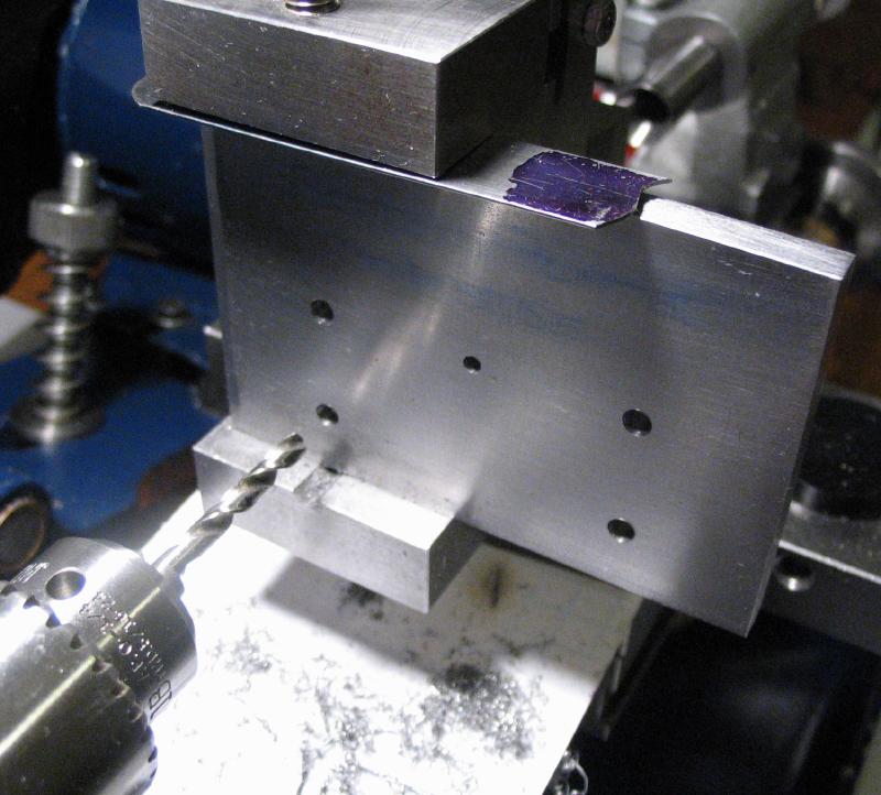
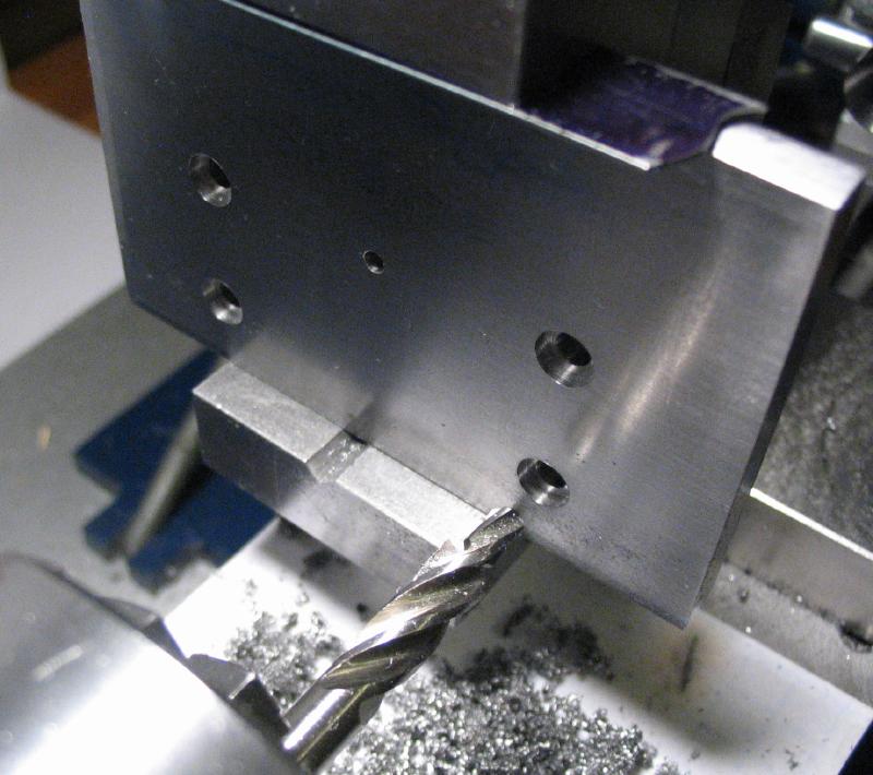
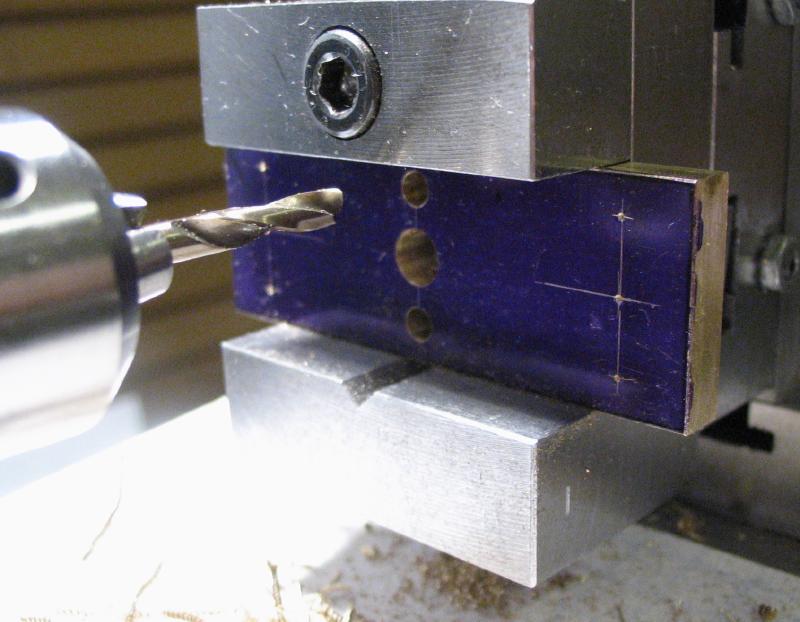
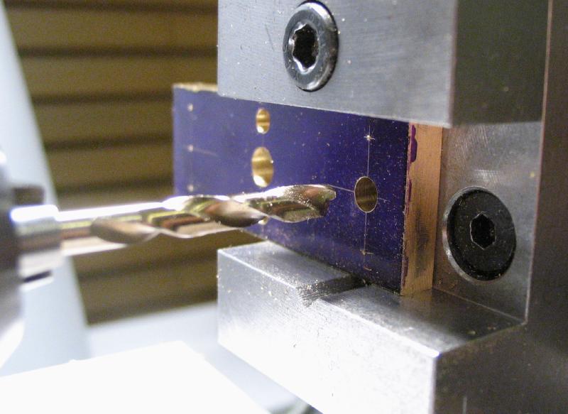
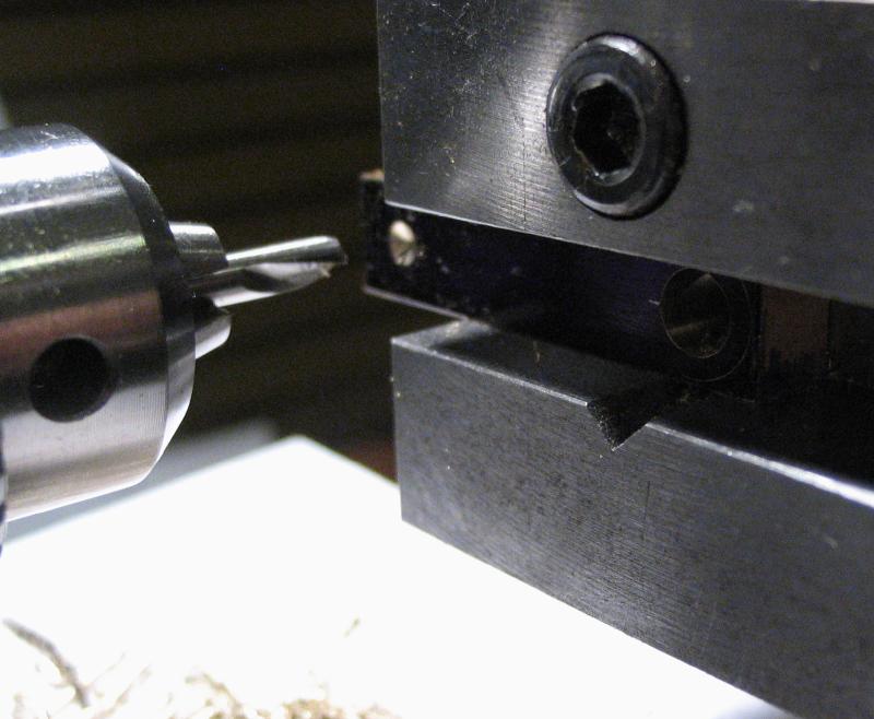
The work was separated (noting the relative orientation of the plates to one another), and each plate step up on the lathe for enlarging the holes with a #29 drill. On the inside faces of the plates, the holes were opened with a #6 counterbore to a depth of 1.6mm. The process is repeated for both plates. Levin recommends a 1/4" counterbore with 1/8" pilot. Curiously, this size is not manufactured, but one could be made. Since there are eight holes to bore and this steel does not seem to machine particularly well, I used a commercially made counterbore for #6 socket head screws. The diameter is slightly smaller than prescribed (0.228"), and will have implications in making the posts below. The plates are reversed and the holes countersunk 82 degrees to a depth to fit the screw heads. I experienced quite a bit of chatter with the countersink, especially approaching full depth.
|
|
|
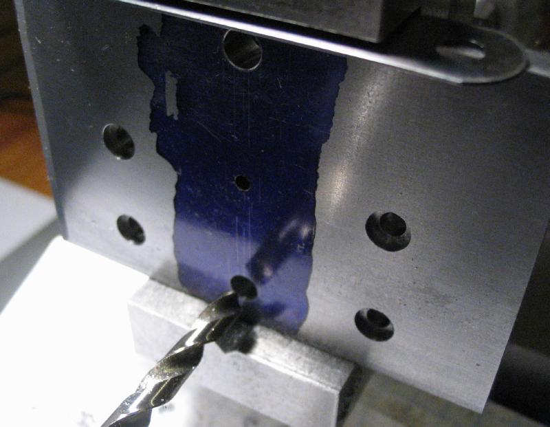
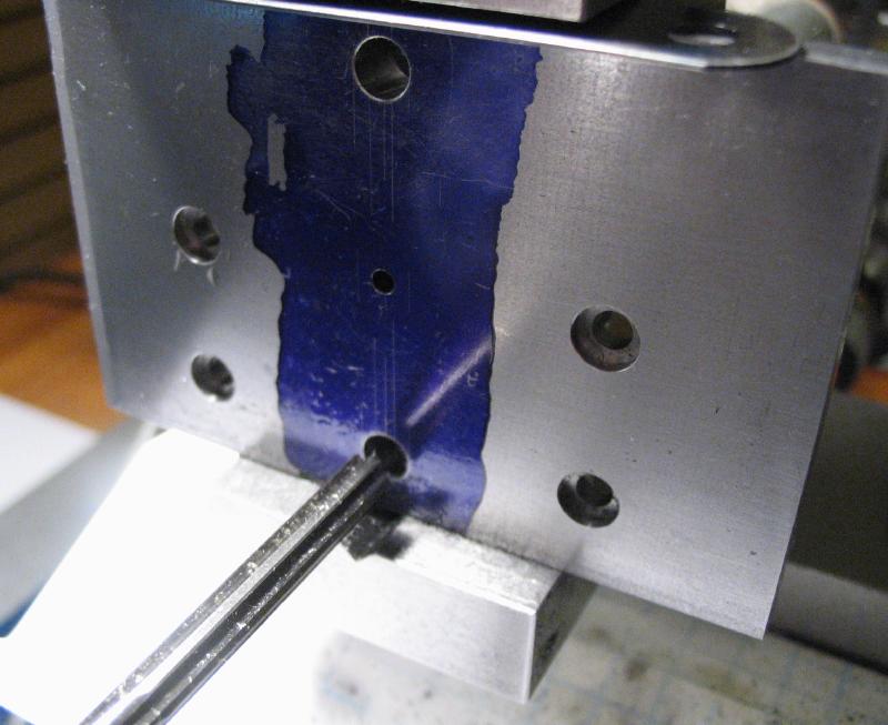
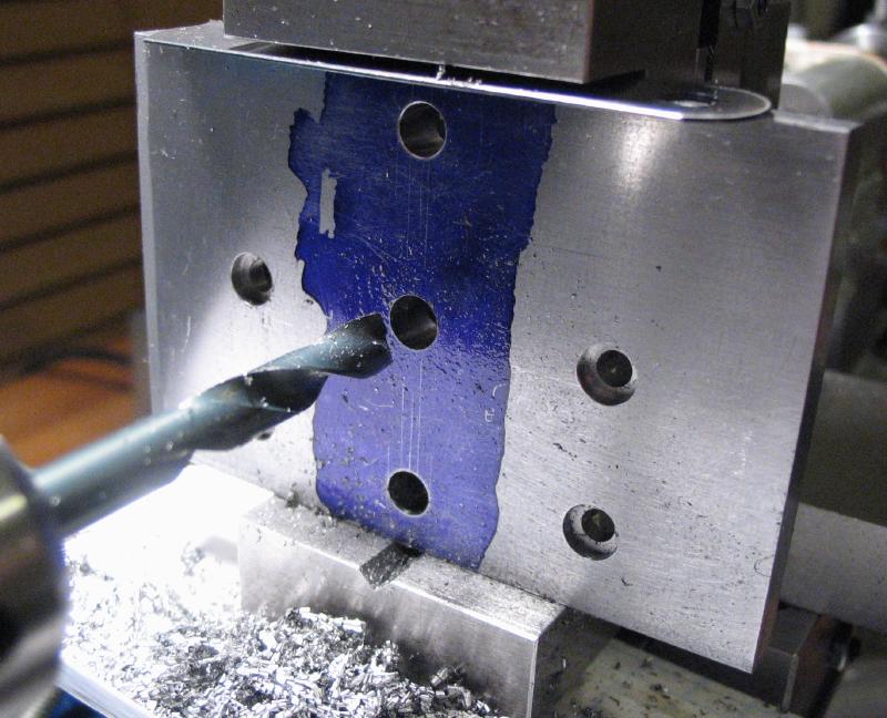
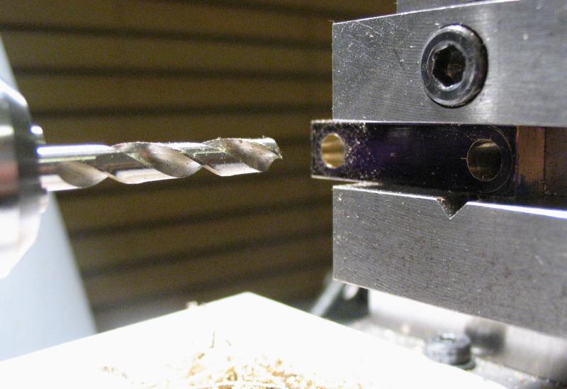
The lower plate was set up in the vise and centered on the center hole. The positions for the T-slot alignment pins were located with the vertical slide and then drilled and reamed 5mm. The center hole was finally drilled to clear the M5 threaded rod for the T-nut. The center hole of the upper plate was enlarged with a 1/4" drill to clear the files.
|
|
|
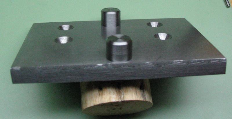
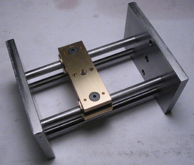
There are four supporting posts, two of which also serve as the guides for the file mechanism. These two posts should be made of drill rod, and the others can be made of brass or mild steel, however, I used 1/4" O-1 drill rod for all of them.
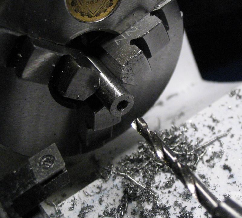
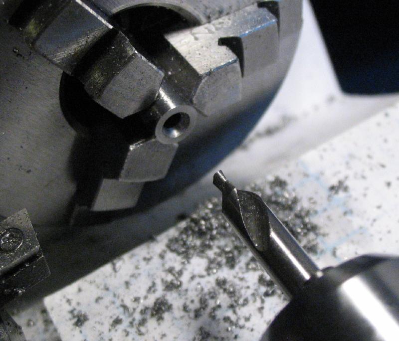
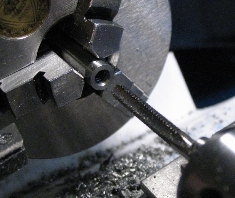
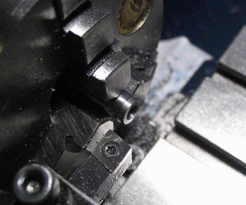
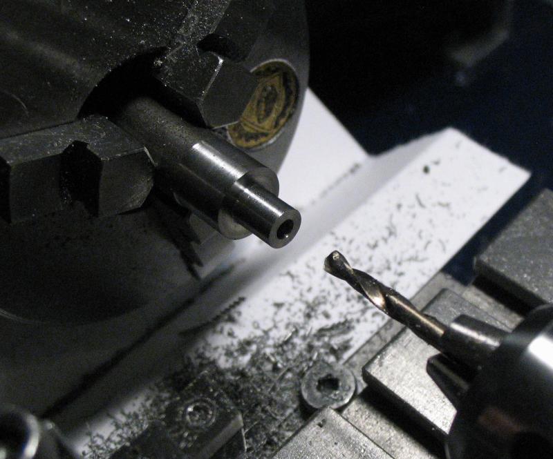
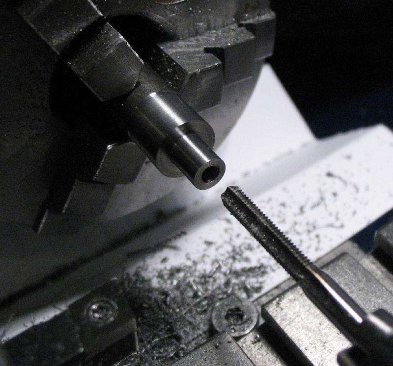
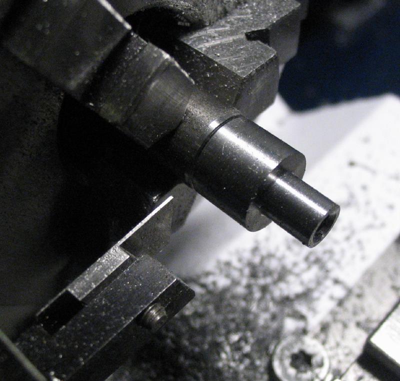
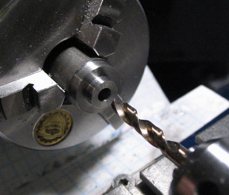
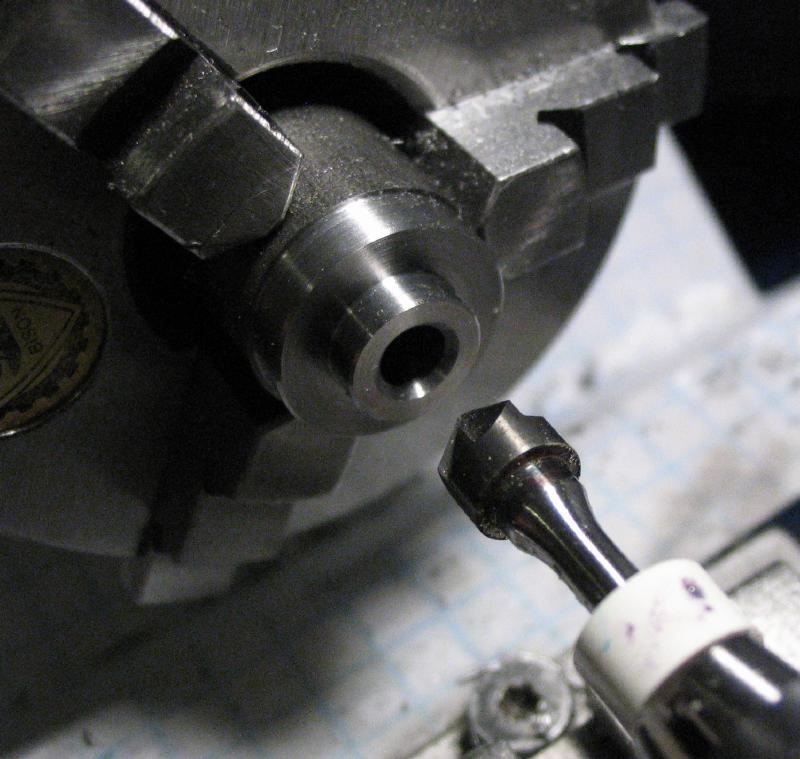
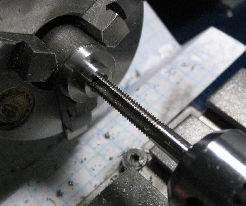
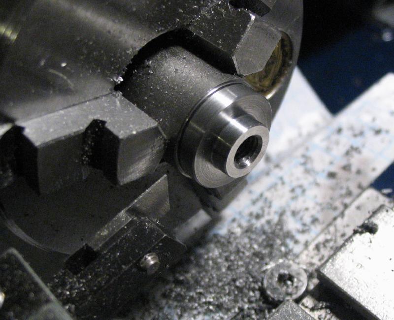
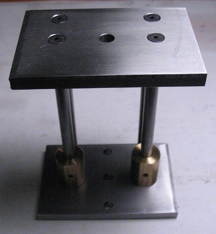
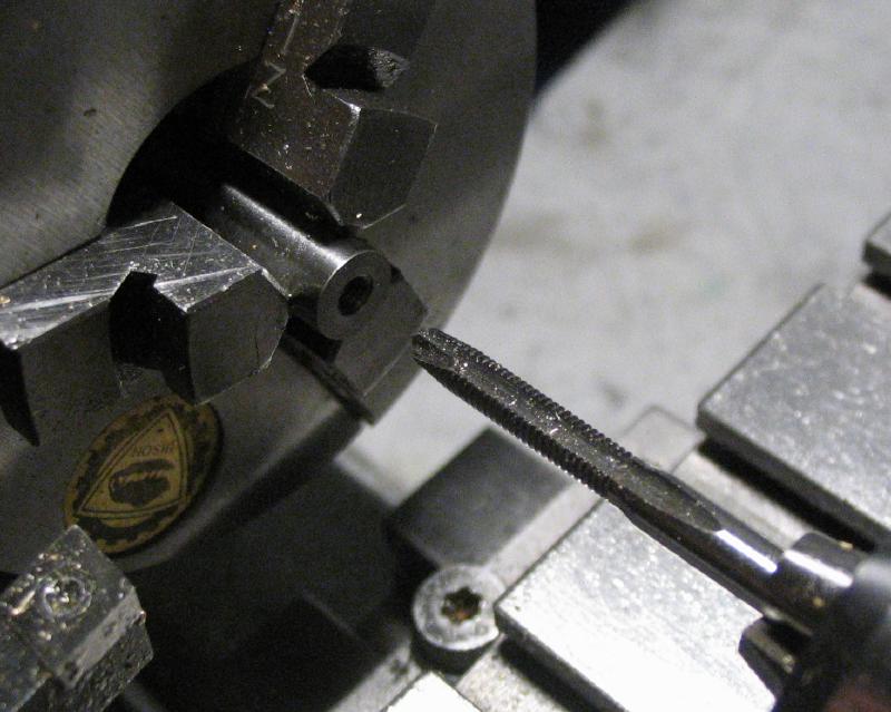
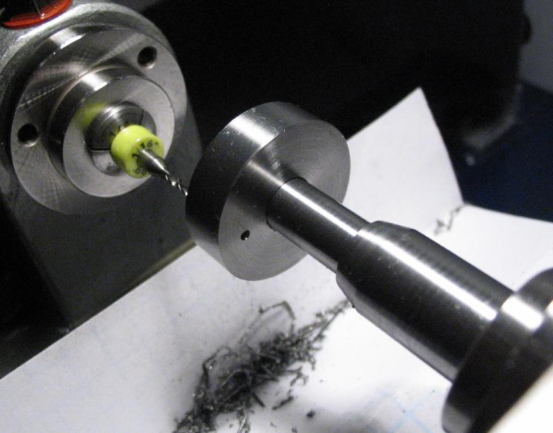
The rod was held in the 3-jaw chuck and faced, spot drilled, and drilled #35 for about 1/2". The hole was countersunk and then tapped #6-32. Since the counterbores in the plate are 0.228", the 0.25" drill rod needs to be turned to fit. The method in Levin's book specifically avoids this step by counterboring the plate 1/4" to fit the rod. The rod was reversed in the chuck and faced down a final length of 92mm and the process above repeated. Four posts are made the same way, and a test fit with the plates is shown.
|
|
|
|
|

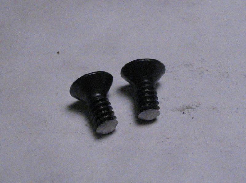
#6-32 countersink head screws - 5/8" length with tips rounded over.
|

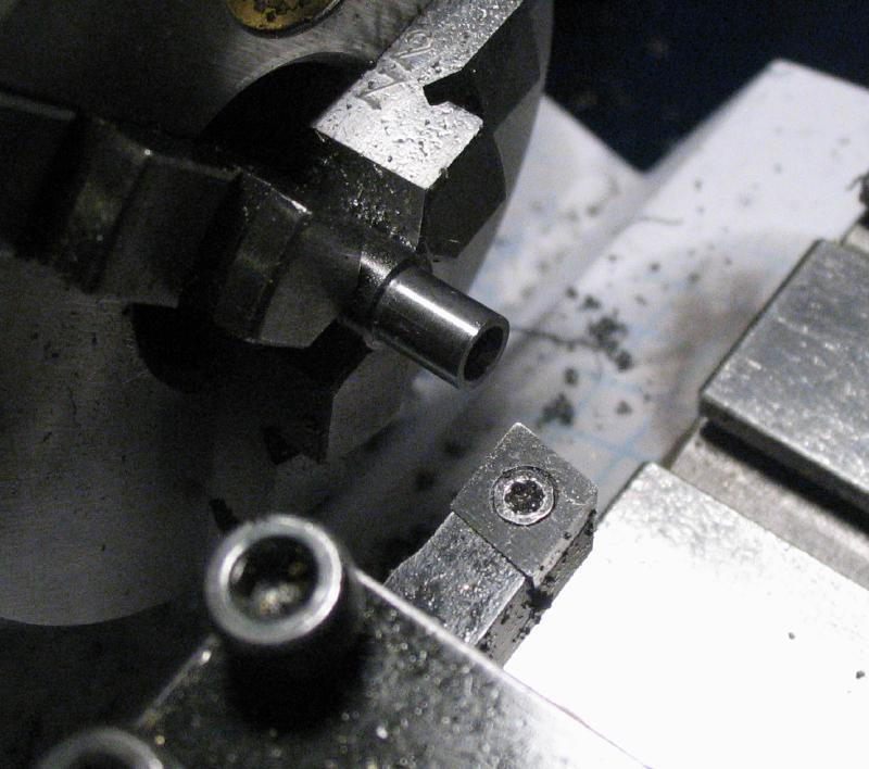
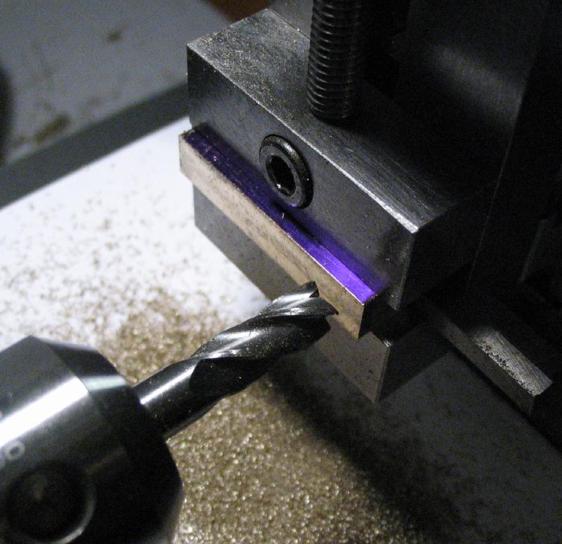
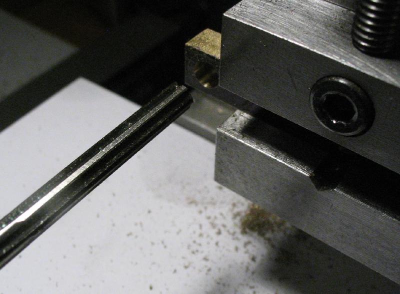
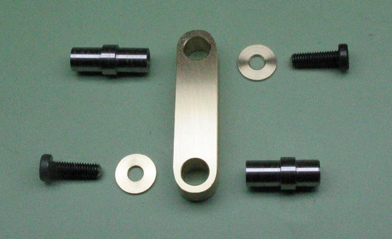
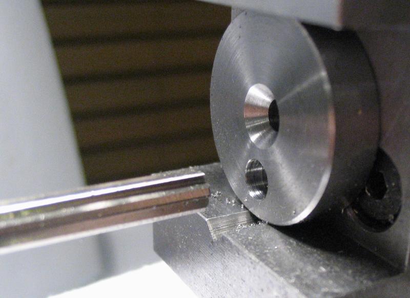
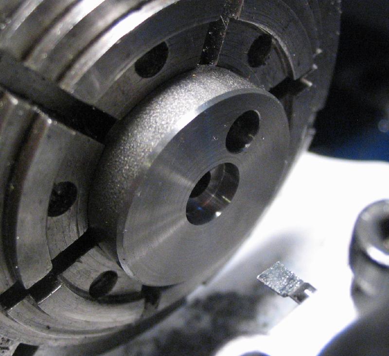
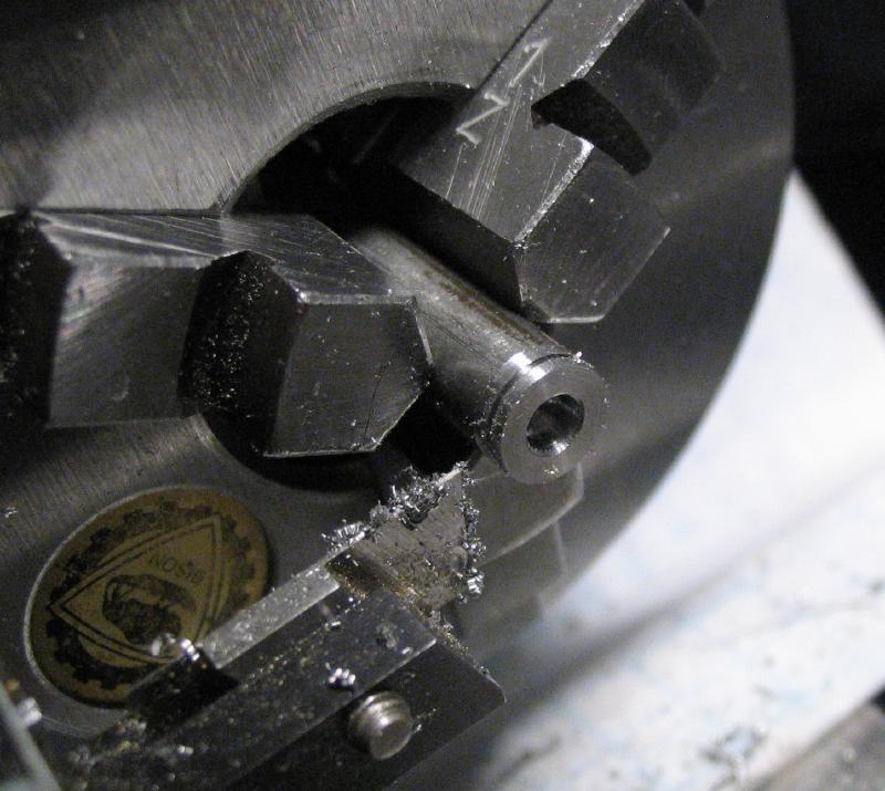
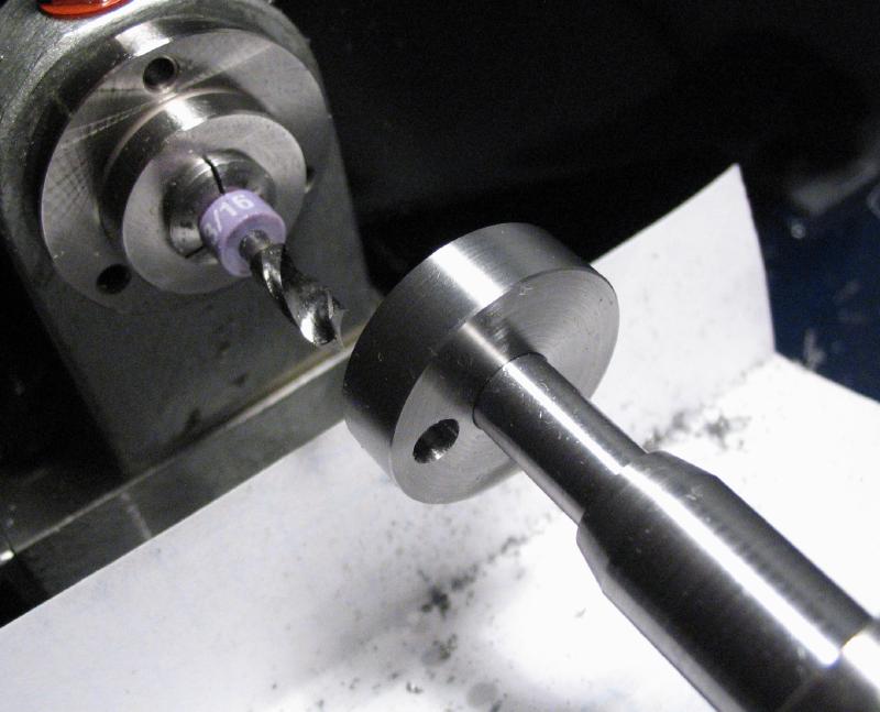
The lathe bed alignment pins were made from 3/8" cold roll steel (12L14). The rod was turned true and left at about 9.4mm for 14mm. The end was turned down to 5mm for 6mm to fit the reamed holes in the lower plate. Although indicated as a driven fit component, I decided to make it a snug fit but secured with a screw. So the rod was drilled 2.5mm and tapped M3x0.5 before parting off.

|
|
|
|
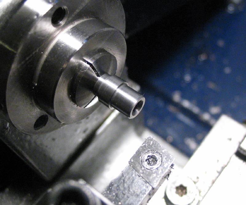
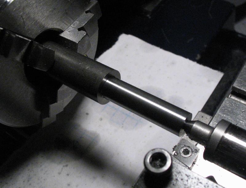
The pins were reversed into a collet and the parted face turned and corner chamfered.

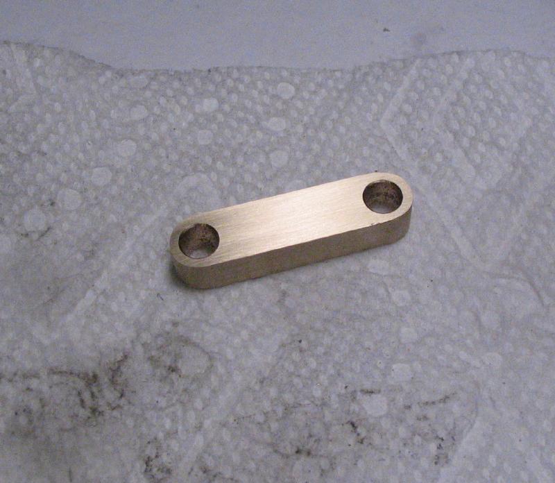
A pair of washers were made from the same 3/8" steel rod, turned true, and drilled 3mm, countersunk and the washers parted off at about 0.8mm thickness. The corners were chamfered with a needle file while still mounted on the lathe and halfway parted off. The reverse side of the washer was countersunk by hand with a jeweler's bur.

|

|
The guide pins are secured in the bored holes of the lower plate with M3 x 10mm low-profile socket head screws and the washers.
|
|
A washer made from 1/2" cold roll steel rod to clear the M5 threaded rod.
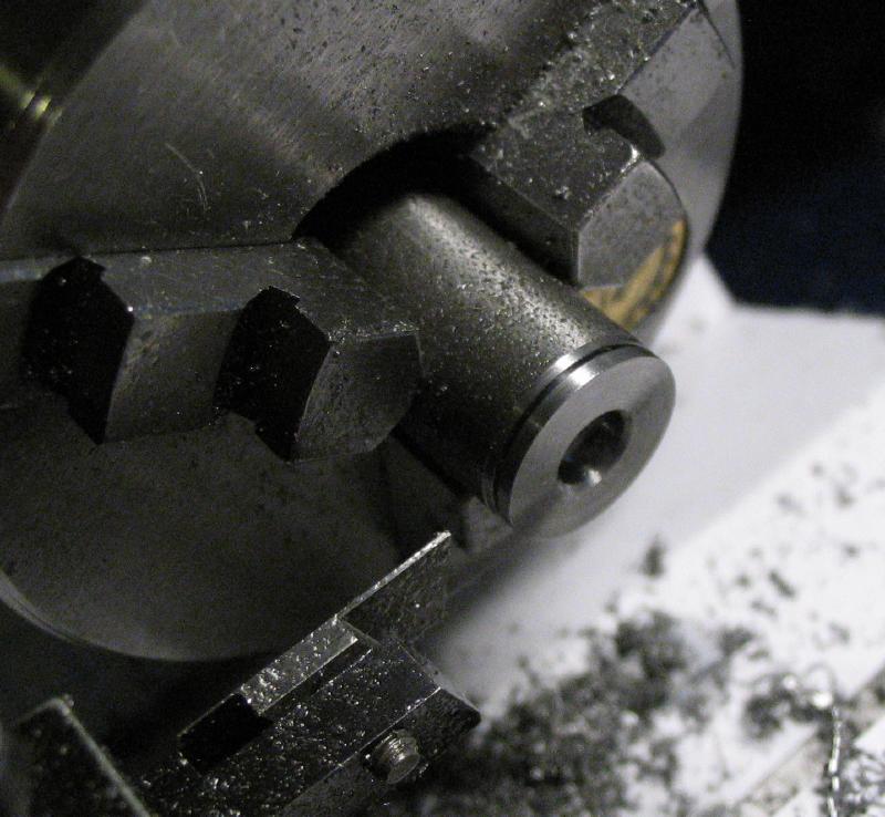
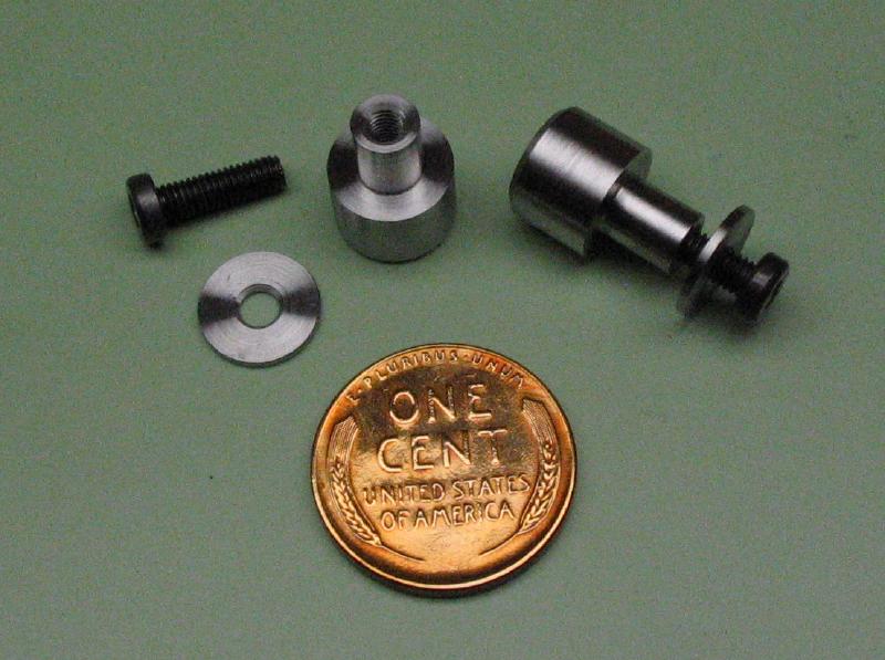
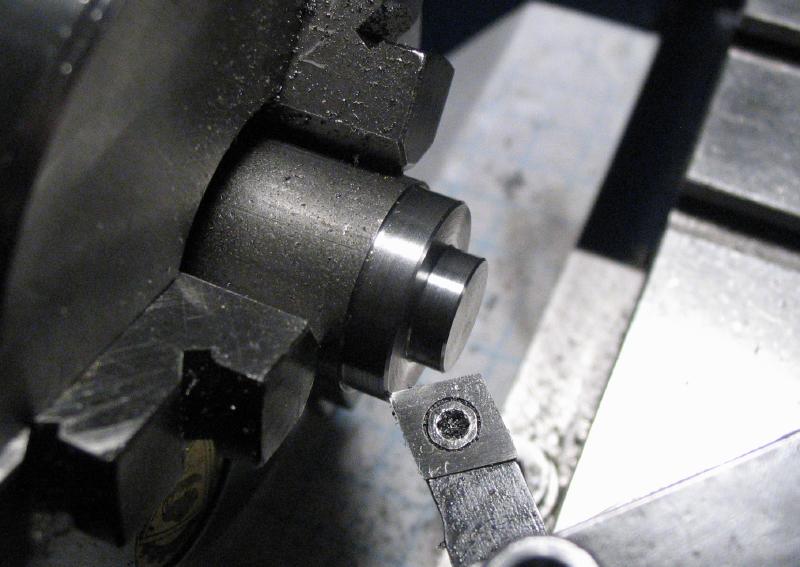
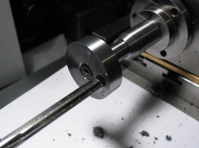
A T-nut was made to fit the slot in the lathe bed. Although drill rod is shown in my initial metal stock "inventory" photo above, the nut was made from a length of 5/8" cold roll steel rod (I suspect it is 12L14); square stock would be preferred, but a round nut should do. It was turned to 15mm diameter, and a boss was turned down to 8.5mm for 2.5mm, and the corners chamfered 45 degrees. The rod was then drilled 4.2mm, countersunk, and tapped M5x0.8. The T-nut was parted off at about 5.3mm total thickness.

|
|
|
|
|
|
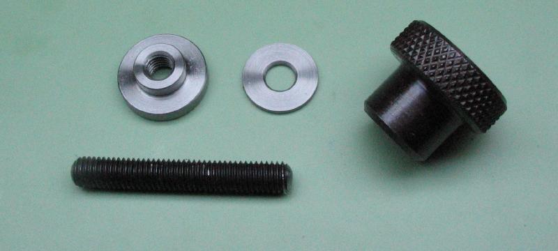
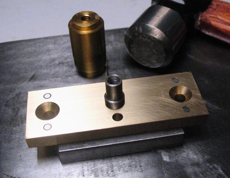
Shown below is the T-nut and washer made above, and a short length of M5x0.8 threaded steel rod and a steel, knurled thumb nut, both of which were purchased.
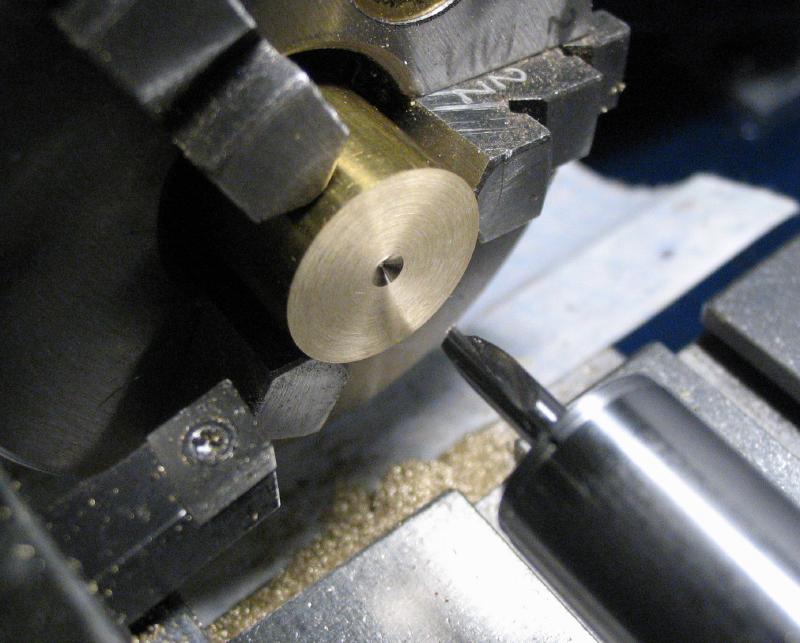
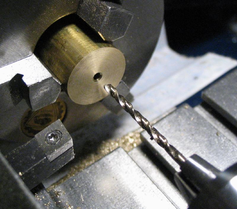
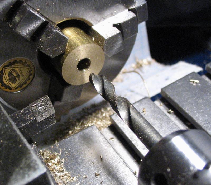
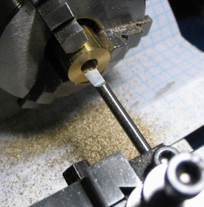
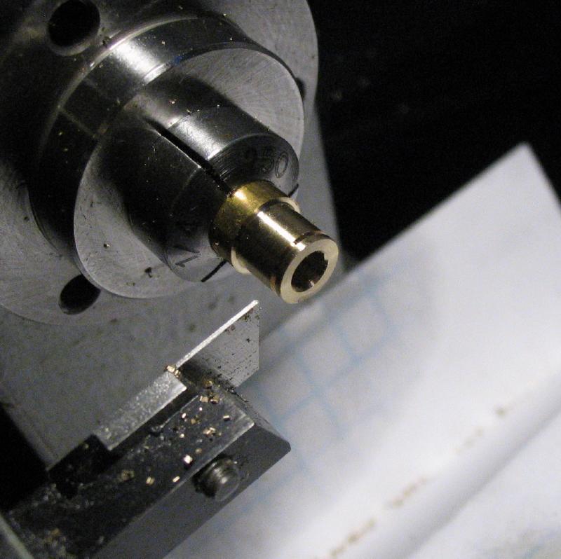
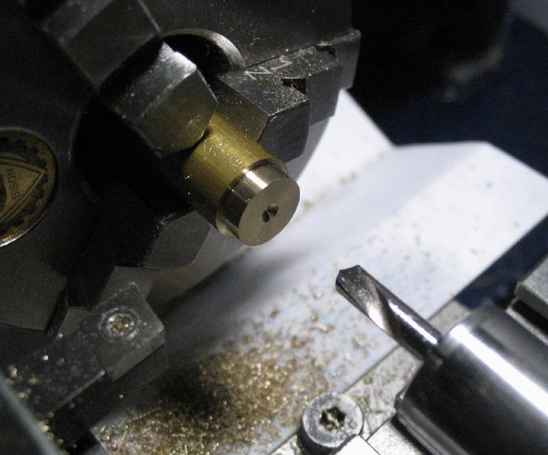
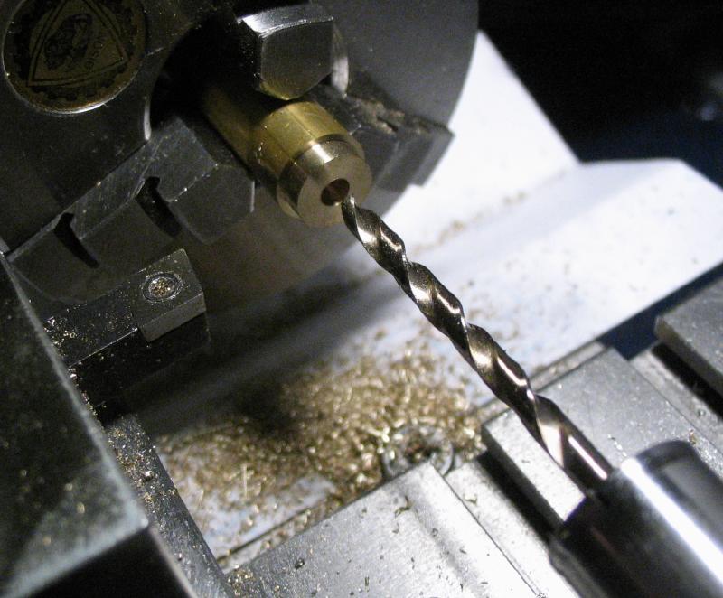
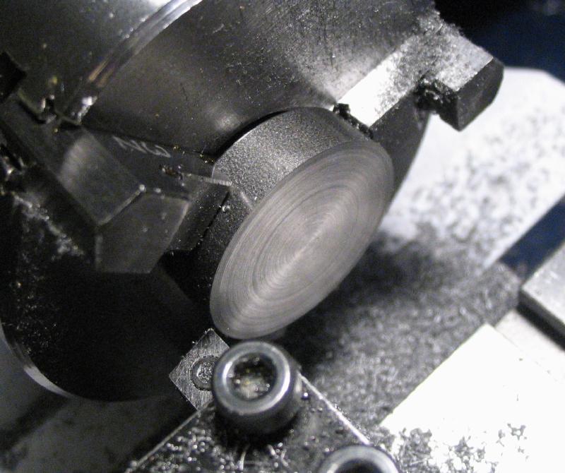
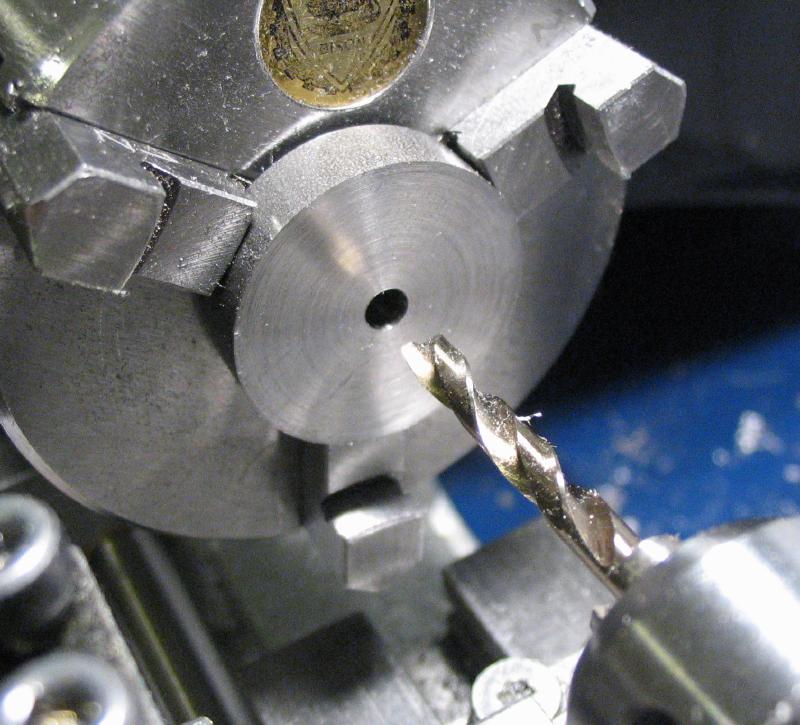
The guide bushings are made from 5/8" diameter brass rod (type 360). The rod was faced. spot drilled, and drilled 2mm and opened with a 5mm drill to admit the boring bar. It was bored open to pass a piece of 1/4" drill rod (same as the posts).
|
|
|
|
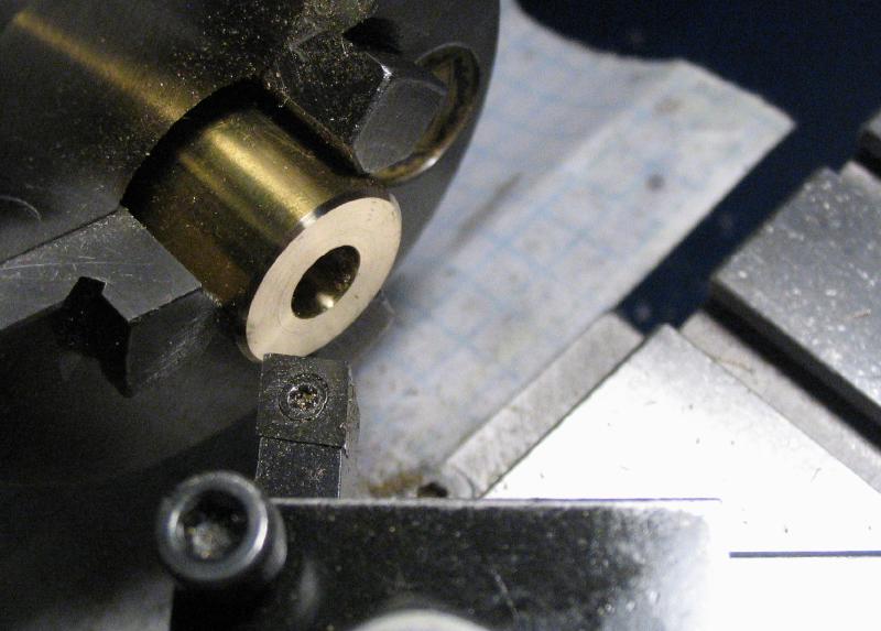
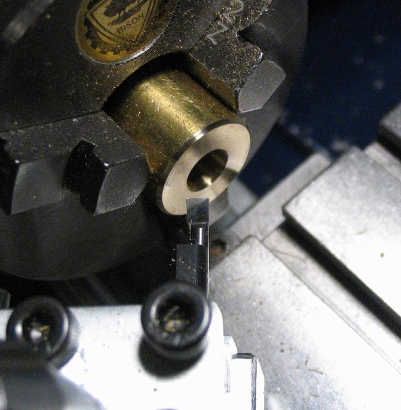
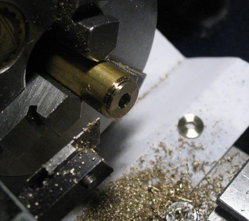
The corners of the bushing were chamfered 45 degrees using the top slide and a lathe tool and boring bar. The work is reversed in the chuck and faced down to the final length, and the corners chamfered as well.
|
|
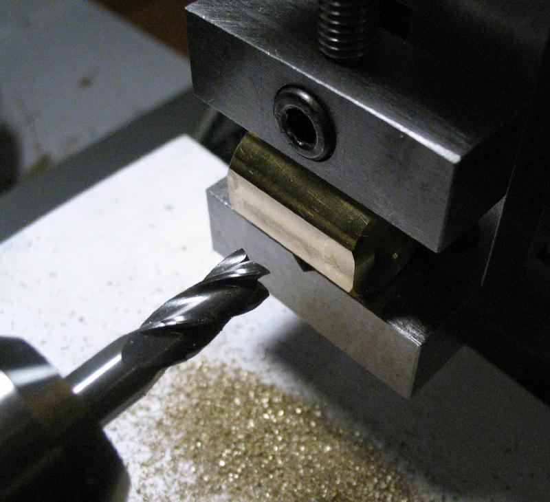
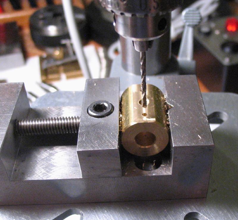
The bushings were then moved to the vise and vertical slide to mill flats for the cross bar to attach. The center was found and drilled for tapping #6-32. The mounting screws on the vise were loosened and the vise moved to the drill press for the tapping step.
|
|
|

|
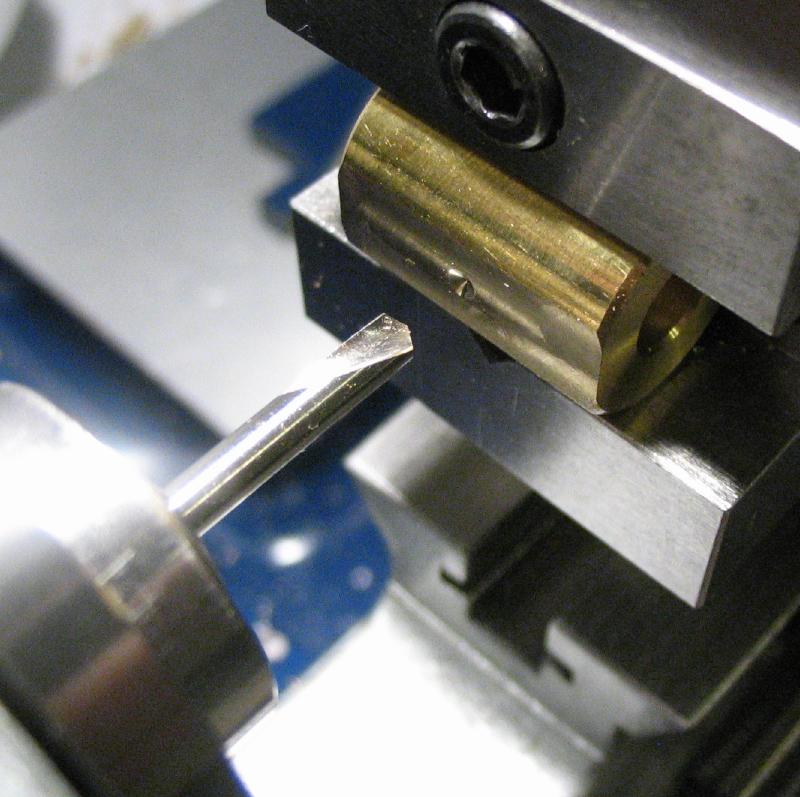
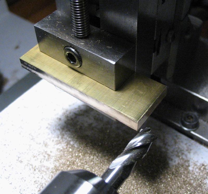
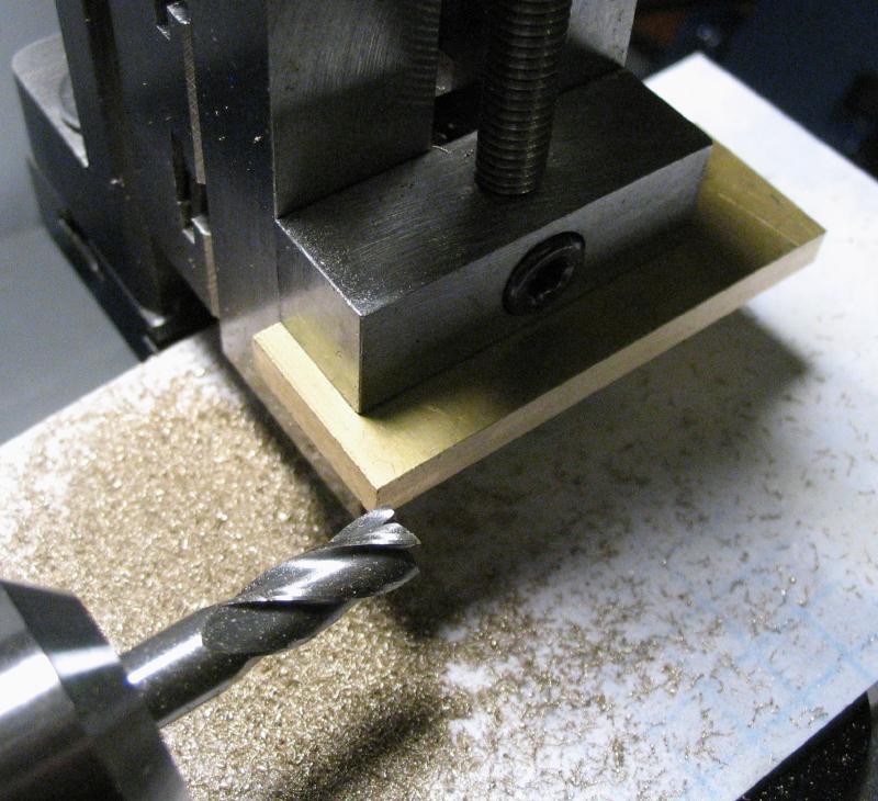
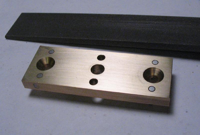
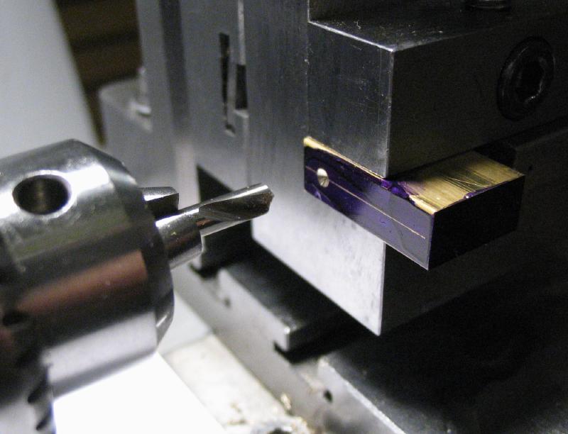
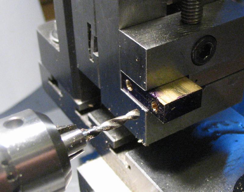
The cross bar was made from 3/16" brass plate. The plate was squared up and brought to a length of 2 1/8" and width of 3/4" by milling. The positions for the drive pin, file holder screws, and bushing screws and pins were laid out and center punched.
|
|

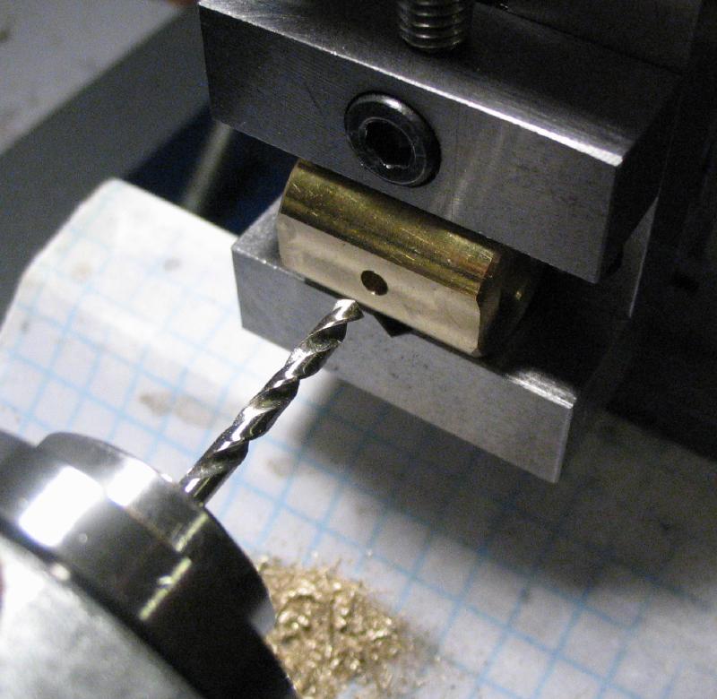
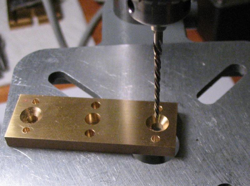
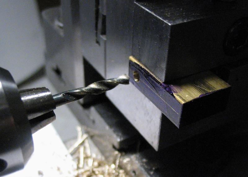
The drive pin hole was drilled 4.7mm and reamed 5mm. Two 3mm holes were drilled to pass the screws to the file holder. Holes were drilled #27 and countersunk for #6-32 screws that attach the bushings. I got ahead of myself and started cleaning the work up, but went back and drilled the steady pin positions with a #52 drill.
|
|
|
|
|
|
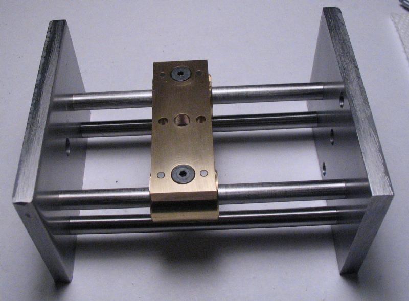
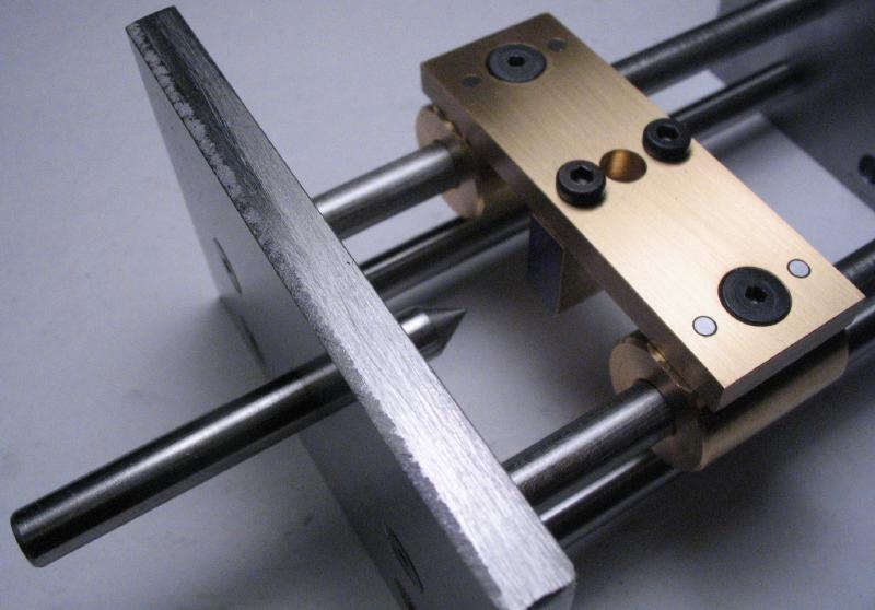
The frame was assembled with the bushings installed on their posts. The cross bar is then attached and secured with the two screws, which are shortened versions of the screws used for the frame.
|
|
|
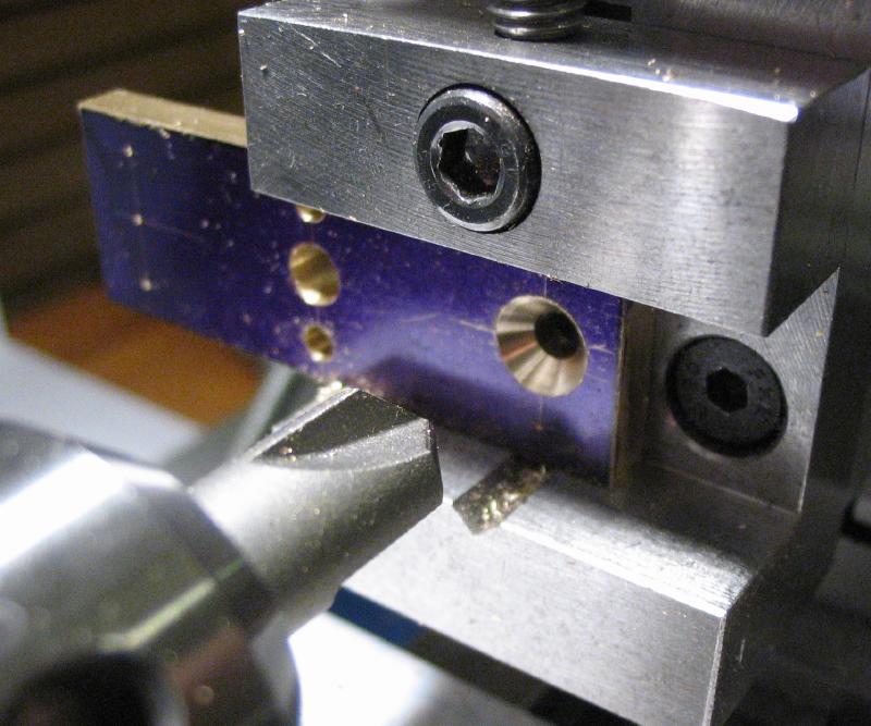
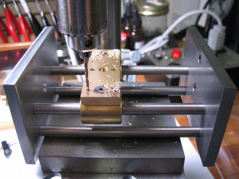
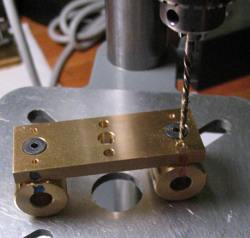
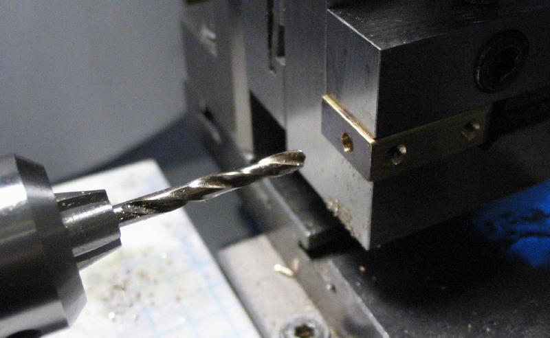
The assembly was setup on the drill press to transfer the steady pin hole positions to the bushings. The spindle depth stop was set on the drill press to prevent the drill bit from reaching the posts. The work was disassembled and the holes in the bushing then drilled through. Perhaps the holes should have been drilled through the other side of the bushing as well to allow the reamer to reach full depth, more on this below.
|
|
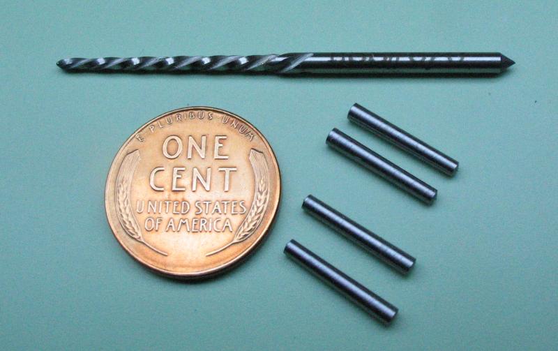
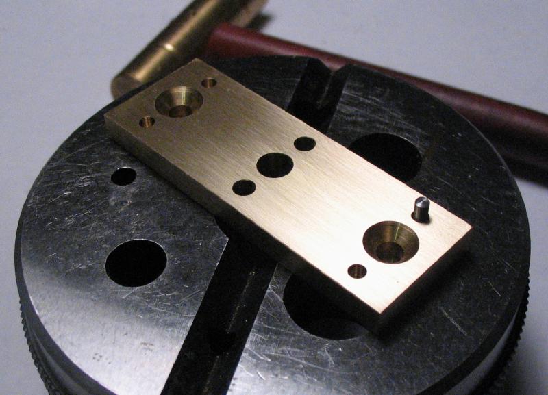
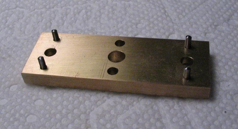
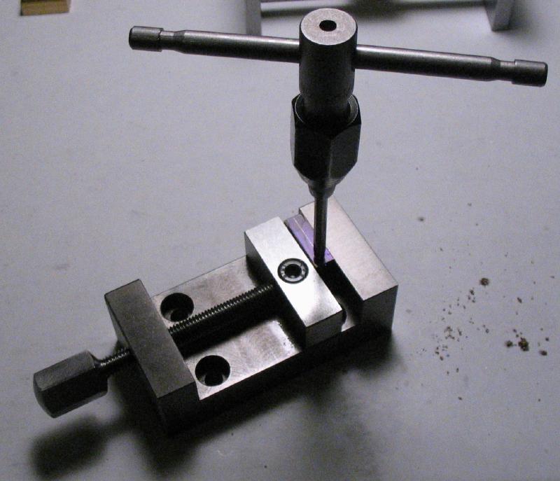
The instructions in Levin's book suggest to me that the assembled crossbar and bushings are reamed together, however, the reamer was not able to go deep enough to fit the taper pins I have. Shown below is the 6/0 taper pin reamer and 6/0 steel taper pins (1/2" length). The reamer was found on ebay, as they are fairly expensive to buy new. It has the helical fluting recommended by Levin. The reaming was started with the crossbar and bushings assembled, but then disassembled to ream the crossbar holes to full depth. Starting with one hole, a taper pin was hammered into place. The matching hole in the bushing was reamed to fit the pin but using a Bergeon cutting broach. The pins were shortened with a jewelers saw and the tips rounded with a cup bur. The top side of the pins were filed flush with the cross bar with flat hand files.
|
|
|
|
|
|
|
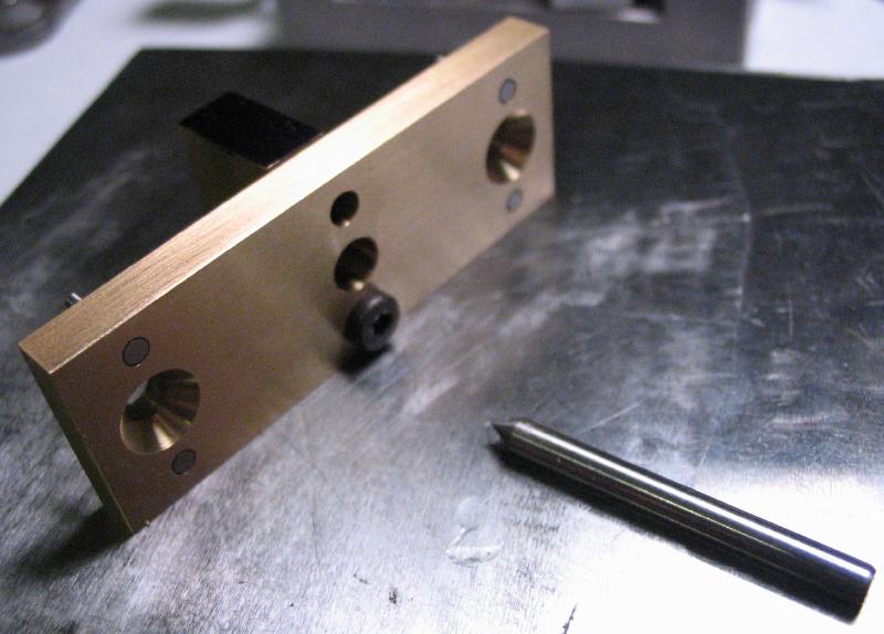
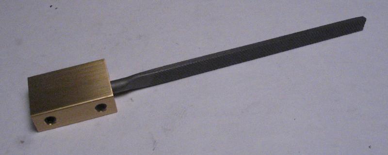
The file holder was started from 1/4" x 1/2" brass bar. A length slightly longer than 3/4" was sawed off and the ends milled to square up and bring it to length. The position for one of the screws was laid out and drilled 2.5mm and tapped M3x0.5. The work could then be attached to the crossbar with a screw and the position for the second screw marked with the aid of a piece of 3mm drill rod that has a center point. The second screw position was then drilled and tapped.
|
|
|
|
|
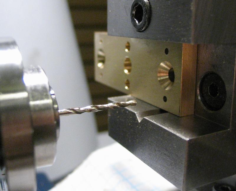
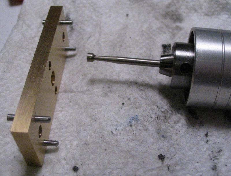
The file holder was attached to the crossbar with both screws and the whole tool assembled. A piece of 1/4" drill rod with a 60 degree center was inserted into the hole of the upper plate and a mark made on the file holder. The mark was center punched and the file holder moved to the vise on the lathe. The center mark was found and drilled #35 and reamed 1/8" to fit the shank of the file.
|
|

|
A pair of washers were made from 1/4" brass rod. It was turned to match the diameter of the screws (5.35mm) and drilled 3mm. They were parted off at about 0.5mm thickness. The ends of the two M3 low-profile socket head screws were rounded over with a cup bur and my simple setup is shown below; the screws were held with the hand-broaching vise and the bur powered with a Foredom tool. Also shown are the brass-tipped set screws for securing the file in place.
|
|
|
One of the pillar files was installed in the holder and the set screws locked. It was mounted in the tool to check the fit.
|
|
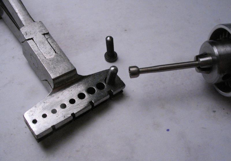
The drive pins for the crossbar and crank were made from 1/4" drill rod. The rod was faced, drilled through 2.5mm, and then tapped M3. It is specified as a driven fit, however, I tapped them for the full length so a screw can be added later, if needed, to secure the pin in place. The pivot for the connecting rod was turned for a length of about 6.4mm and the final diameter slightly under 5mm (measured 4.96mm). The pivot surfaces were smoothed with India and hard Arkansas stones.

|
|
|
The pin was reversed into a 5mm collet and turned to 5.05mm to friction fit the reamed hole in the crossbar or crank plate - the lengths of which were made slightly short of the 3/16" and 1/4" thicknesses of each, respectively. The hub was turned true and left at about 6.1mm.
|

|
The connecting rod was made from 1/4" x 1/2" brass bar. It was squared up and reduced to about 8.2mm in width by milling. The locations for the two pivot holes were laid out and the work returned to the machine vise to drill and ream the holes 5mm. Finally, the ends of the rod were rounded over with a file. The surfaces were cleaned up with 800 grit emery paper.
|
|
|
|
|
A pair of washers were made to retain the connecting rod on the drive pins. The washers were made from 3/8" brass rod, turned to 8mm and drilled 3mm. The hole countersunk lightly and corners chamfered with needle file while parting off. The low profile socket head screws were used here. Before driving the pins into their respective homes, the works was assembled for a trial fit.
|
|
|
|

|
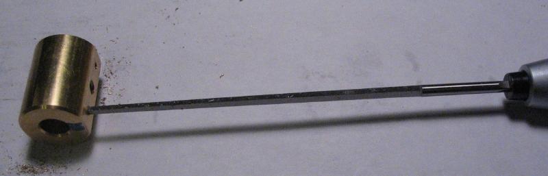
The drive pin was driven into the cross bar with a hammer and using a piece of brass rod from the scrap box in between.
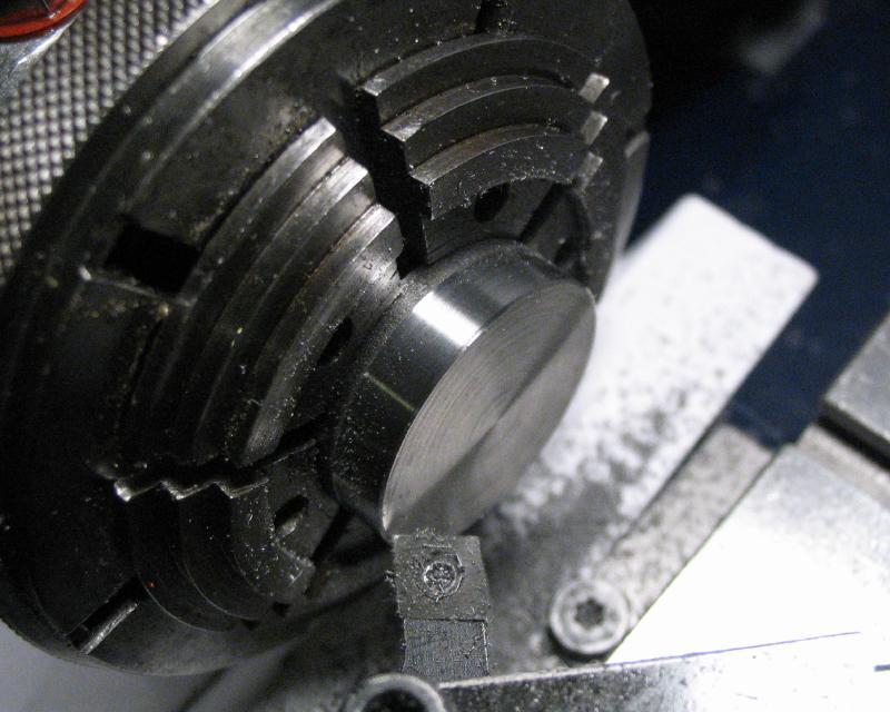
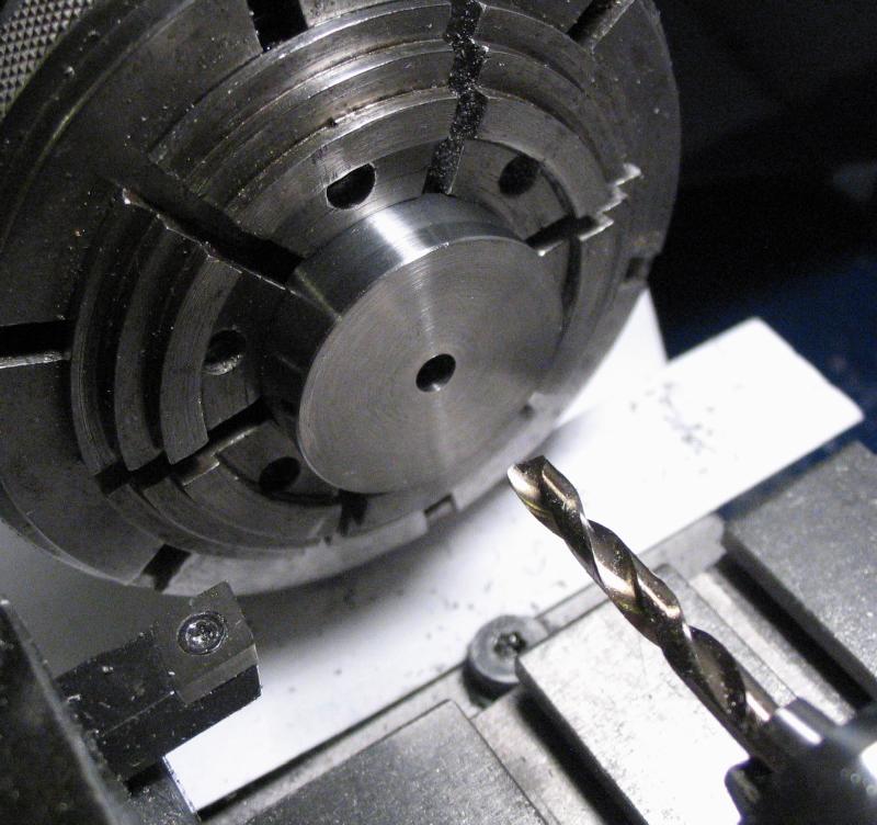
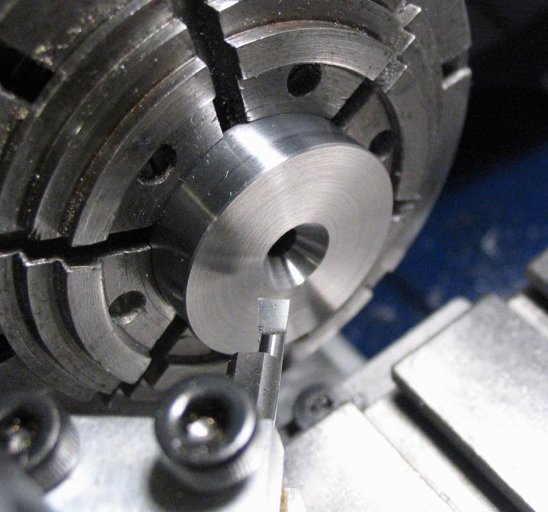
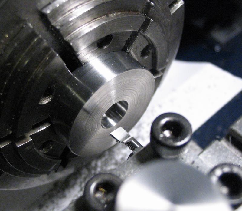
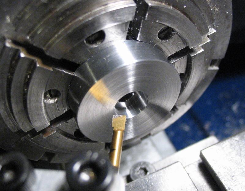
The crank plate was made from 1" diameter steel rod (12L14). A disc was sawed off and faced on both sides and brought to a thickness of 6.5mm. The disc was drilled #27 to clear the threads of a #6-32 screw. It was moved from the 3-jaw to the 6-jaw bezel chuck for better access with the boring bar, which was used to bore the 82 degree countersink for the screw head. The corner was chamfered 45 degrees as well.
|
|
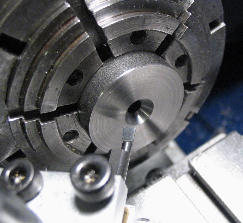
|
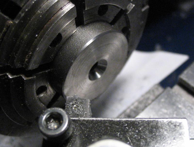
|
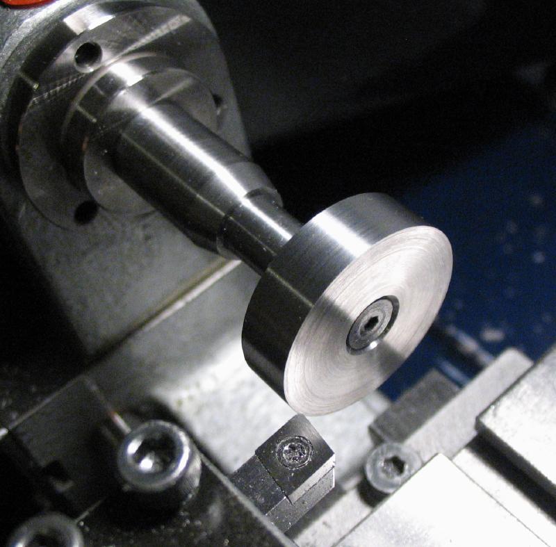
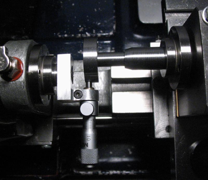
The disc was moved to the vise and vertical slide to drill and ream the position for the drive pin. The work was returned to the 6-jaw, and the center hole on the reverse face bored open to 8mm for depth of about 2.5mm.
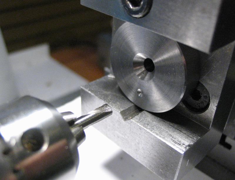
|
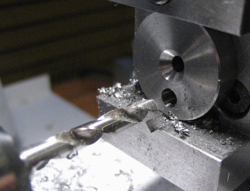
|
|
|

|
A screw will be used to secure drive pin in the crank and another washer was needed, made from 1/4" steel rod.
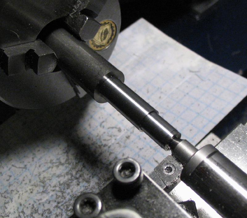
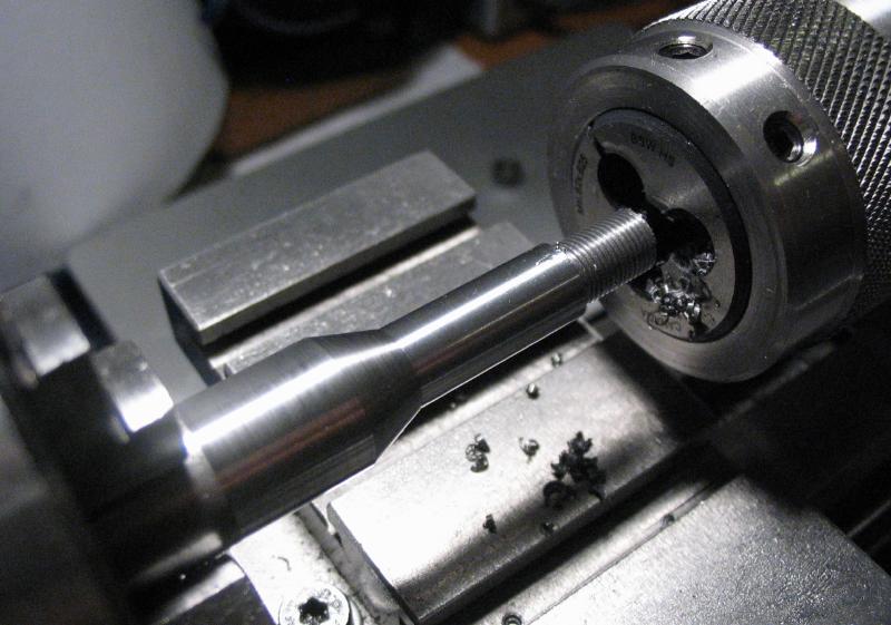
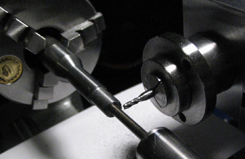
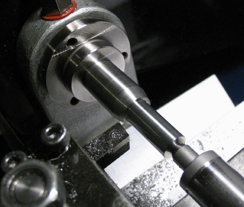
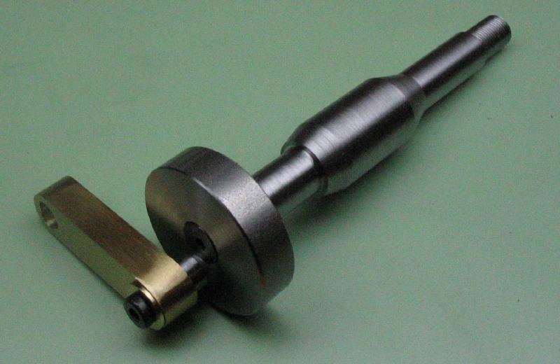
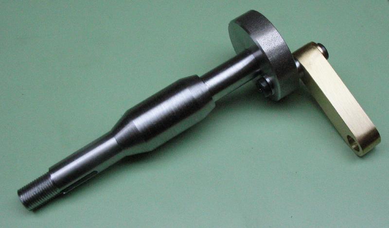
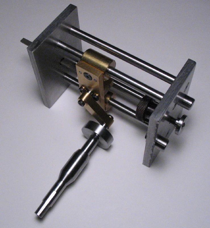
The design in Levin's book uses a 1/4" shaft on the crank that can be held in a collet in the lathe headstock. Instead, I decided to make a dedicated drive shaft that fits directly into the headstock of the lathe without the need for a collet. A roughly 70mm+ length of half-inch steel rod (12L14) was machined to match the shank of a B8 collet. This process is described on various other pages of the site (e.g. here), but photos of each step are shown below.

|
|
|
|
|
|
|
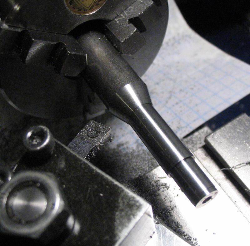
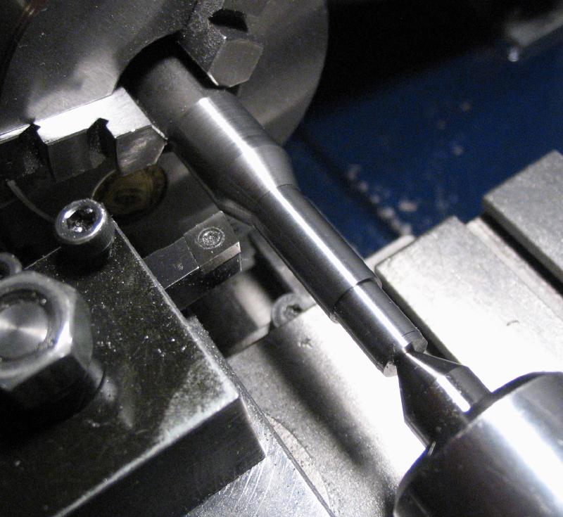
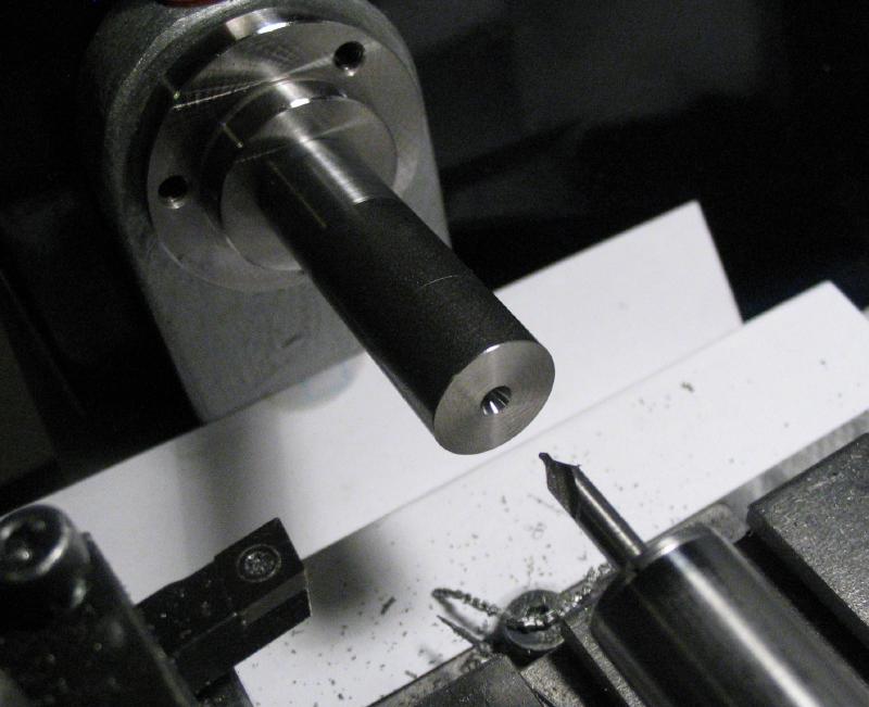
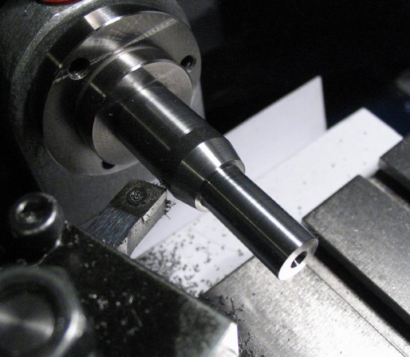
Once the 'collet shank' of the arbor is formed, the work can be mounted directly in the headstock to machine the other end. It was faced and center drilled for tailstock center support. The arbor was turned to fit the bore in the crank disc and for a length of 17.5mm. The corners were chamfered and the remaining diameter turned true.
|
|
|
|
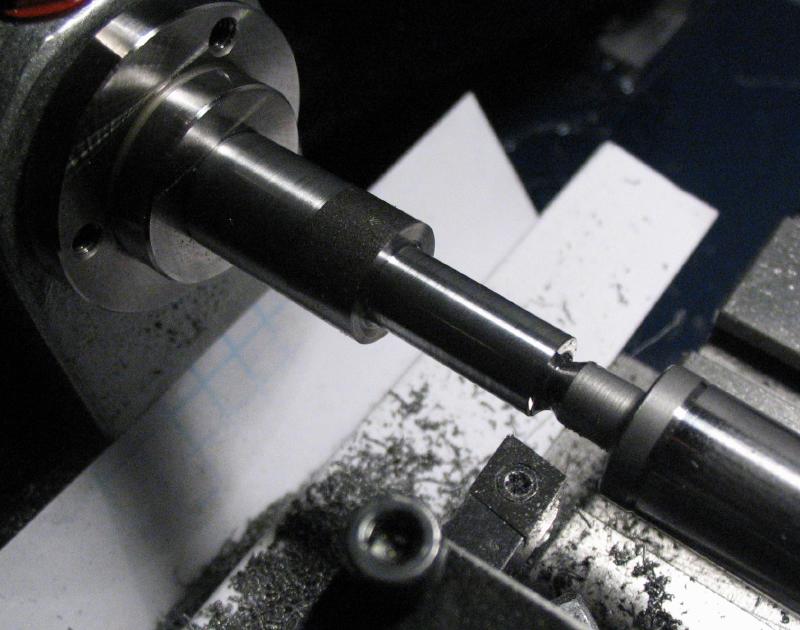
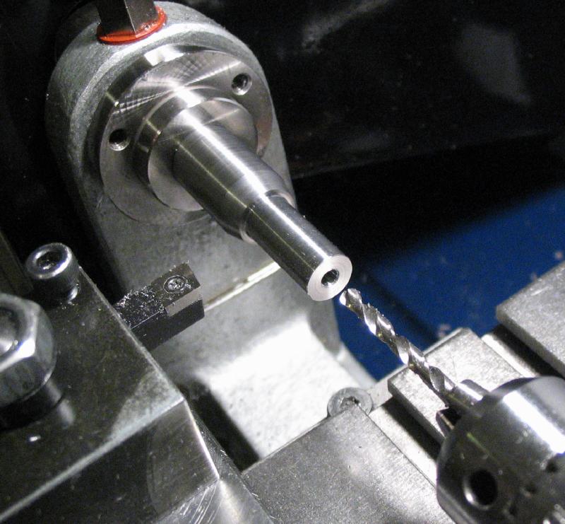
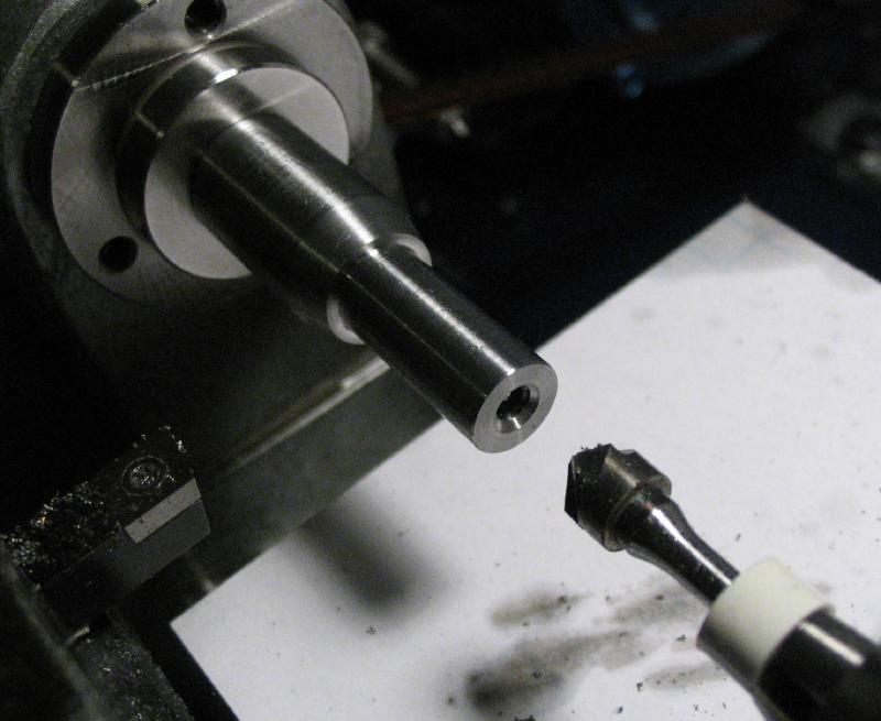
The arbor was then drilled #36 for about 1/2", tapped #6-32, and the hole countersunk.
|

|
|
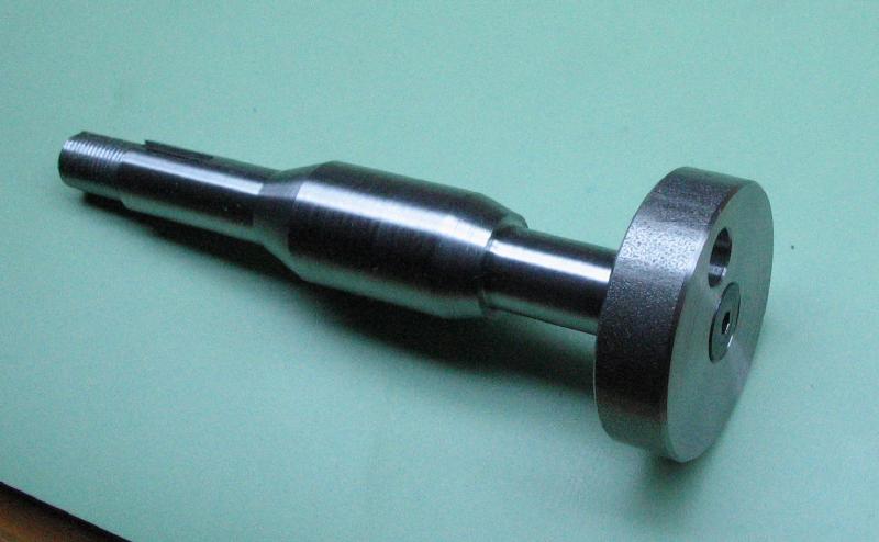
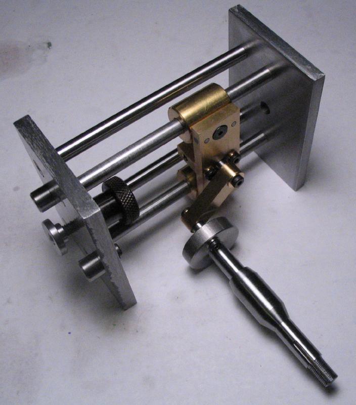
The crank disc can then be attached to the arbor with a countersunk screw. Also shown with the drive pin and connecting rod installed.
|
|
|
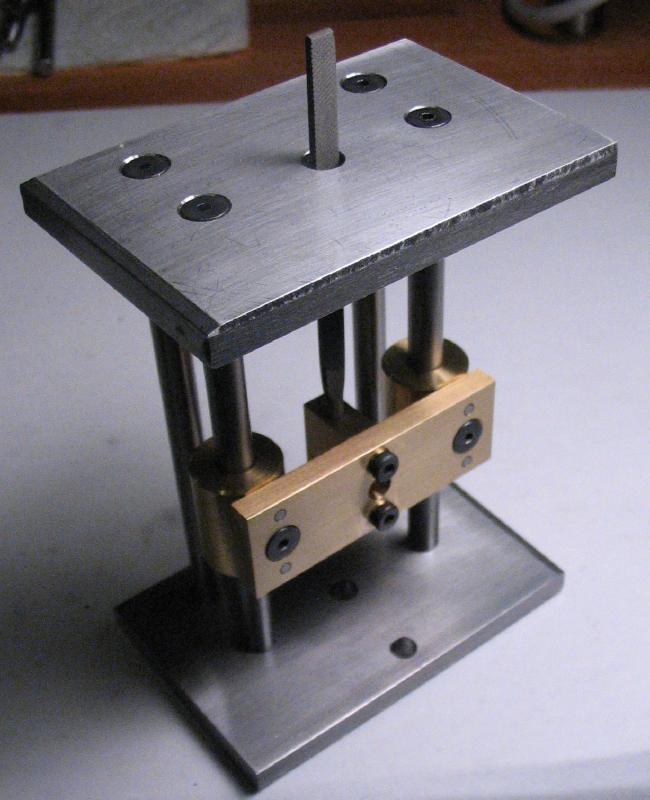
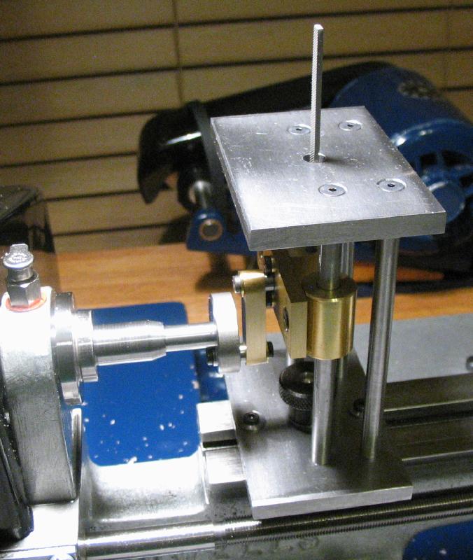
With all the components machined, the tool was assembled for a trial fit. The sliding action is fairly tight.
|
|
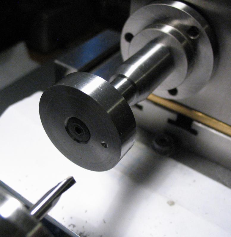
When trying to run the machine, there was an unacceptable amount of run out with the crank. The arbor runs true, so the error is in crank disc. It was remade with some changes to the process used above. Another disc of 1" steel rod was faced but the outer diameter turned true before reversing and repeating on the other side; the thickness was left oversize (about 7.2mm). It was drilled and generously countersunk to fit the #6-32 screws, and the reverse side of the disc bored to fit the arbor to a slightly deeper depth this time (about 3mm).
|
|
|
|
|
The disc was installed on the arbor for finishing. It was faced and turned true, and the work moved to the dividing head mounted on the cross slide. The location for the drive pin was set up, spot drilled, drilled 1/16", then 3/16", and finally reamed 5mm. The drive pin was a tighter fit this time, and overall, the revised method resulted in a more true-running crank.
|
|
|
|
|
|

|
|
|
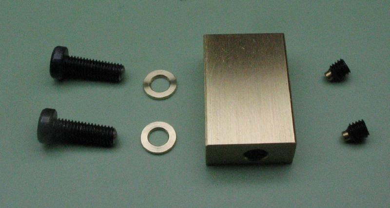
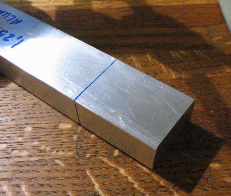
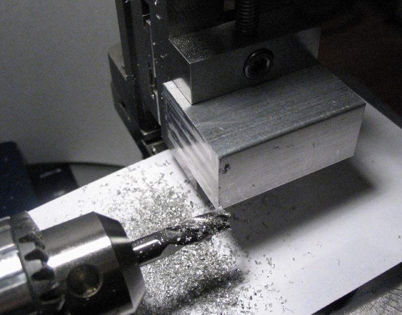
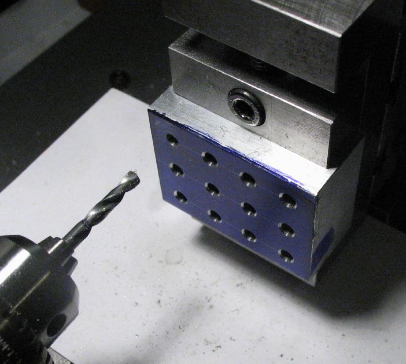
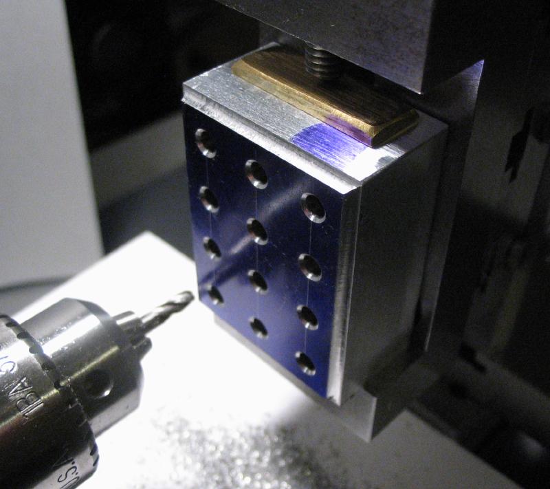
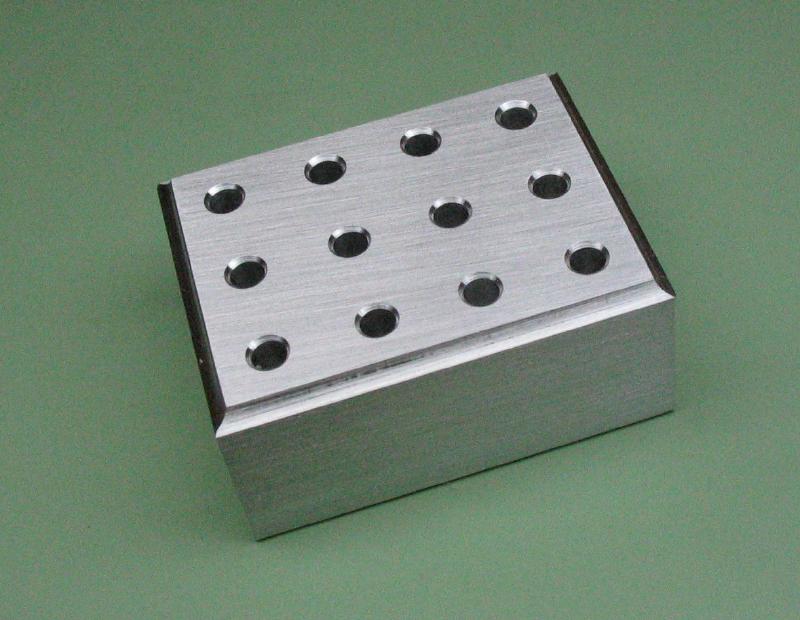
A 1-5/8" length of 1.25" x 0.75" aluminum bar (6061) was sawed off and milled to length, drilled 1/8" to a depth of about 15mm, and countersunk for a dozen positions. The block is for holding the files when not in use. I have ten files, but left room for a couple more. The corners of the block were scalloped using half the width of a 1/8" ball end mill. The surfaces of the block were smoothed on 600 grit emery paper.
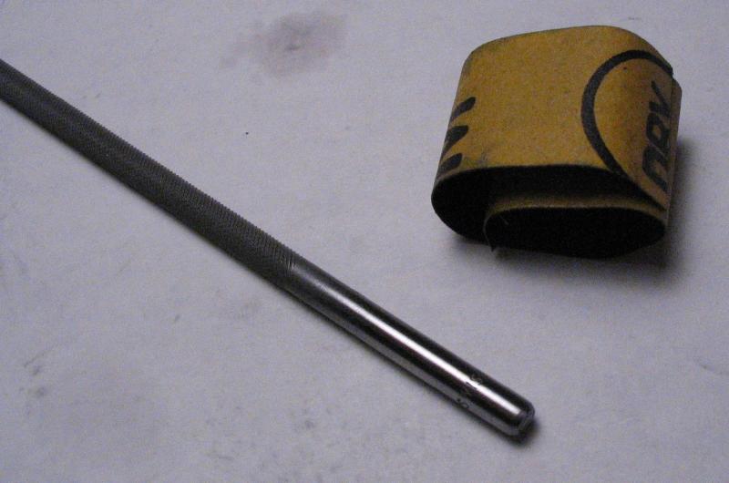
The files are a very tight fit in the reamed hole of the holder of the tool as well as in the drilled holes in the aluminum block. There are stamp marks in the shank of the files (e.g., 'Swiss' and '00' or '2') that raised burs. These were smoothed with an Arkansas slip stone and the whole shank then smoothed with 400 and 800 grit paper to remove the somewhat rough surface. Most of the files needed little attention, but the one shown below was about 0.04mm oversize. Fortunately, it is a one of the round files and easily turned by hand with the shank wrapped in emery paper.
|
|
|
|
|

|
