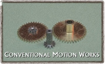
Motion Work version II
Well, one may be curious why there is a second motion work page. I initially experienced some difficulty in completing the retrograde motion work, found under Motion Work I. Ultimately a working version of the mechanism was made, but in the mean while I decided that an alternative should be made. It is a conventional type of motion work, with concentric minute and hour hands.
I begin by making a sketch, and I decided to use my set of 0.25 module cutters, even though a smaller module would be more ideal, but it would require the purchase of least two more pinion cutters. I am using a ratio of a 12 leaf cannon pinion to a 36 tooth minute wheel (1 hour to 1/3 hour), and a 10 leaf minute pinion to a 40 tooth hour wheel (1/3 hour to 1/12 hour). Therefore, one rotation of the cannon pinion (carrying the minute hand) will result in 1/12th of a rotation of the hour wheel (hand).
I begin by making a sketch, and I decided to use my set of 0.25 module cutters, even though a smaller module would be more ideal, but it would require the purchase of least two more pinion cutters. I am using a ratio of a 12 leaf cannon pinion to a 36 tooth minute wheel (1 hour to 1/3 hour), and a 10 leaf minute pinion to a 40 tooth hour wheel (1/3 hour to 1/12 hour). Therefore, one rotation of the cannon pinion (carrying the minute hand) will result in 1/12th of a rotation of the hour wheel (hand).
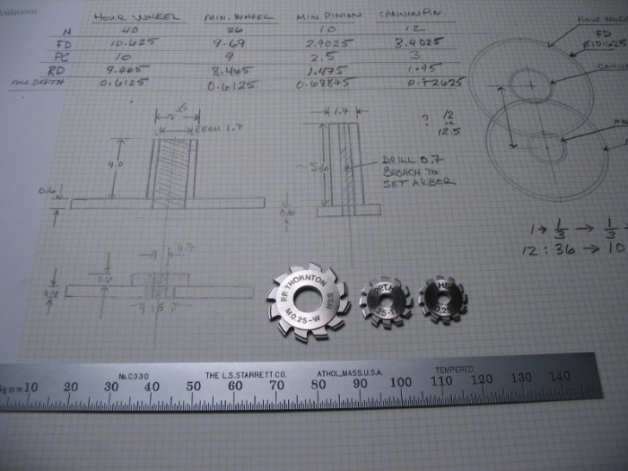
| motion_work_ii_-_hand_drawing.pdf |
Cannon Pinion
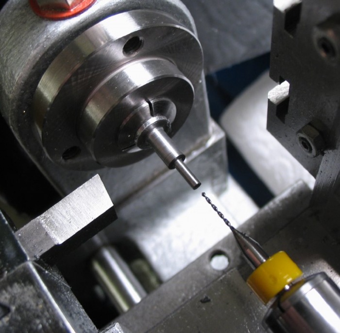
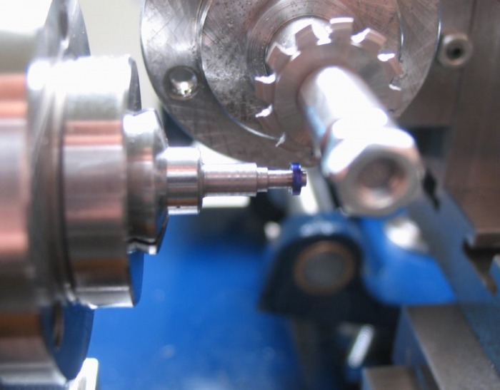
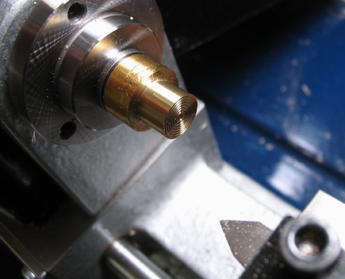
I begin with the cannon pinion, it took three attempts to get one that I was satisfied with. Most of the photos were taken during the first attempt, and the basic setup did not change, however, you may notice some dimensional variations. 7mm O-1 drill rod was turned down to the pinion leaf full diameter plus 0.05mm to allow for topping with the cutter (3.4525mm). I did not allow enough clearance for the cutter in the first attempt, and it is plainly visible in the latter photos.
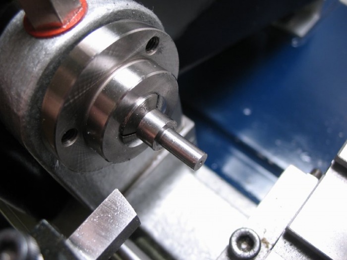 Not enough clearance |
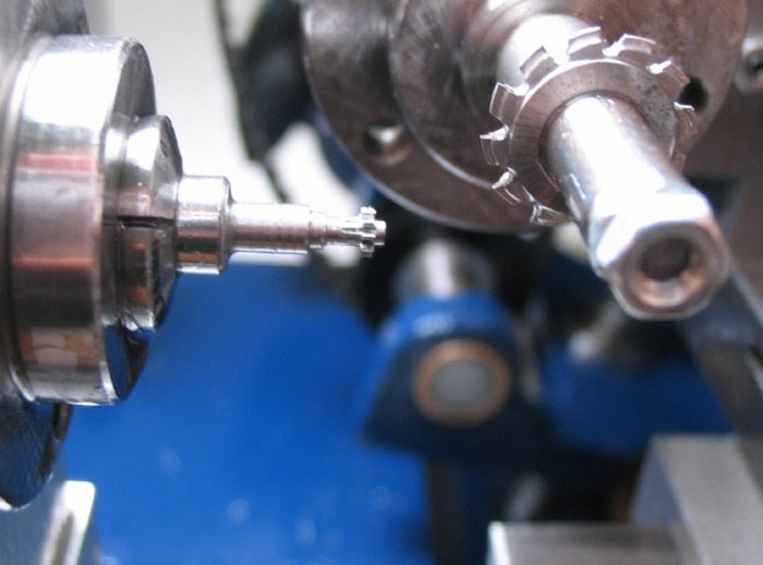
 Third try.... |
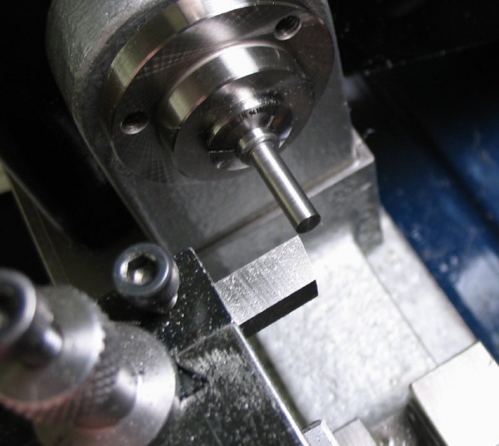
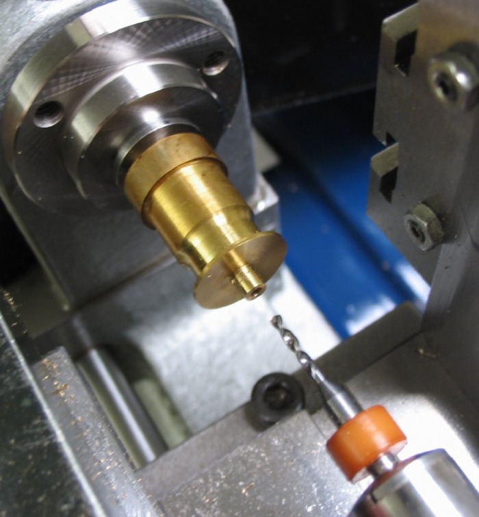
The pinion can be drilled for mating/broaching later to the setting arbor. It is also turned down to act as the arbor for the hour wheel.

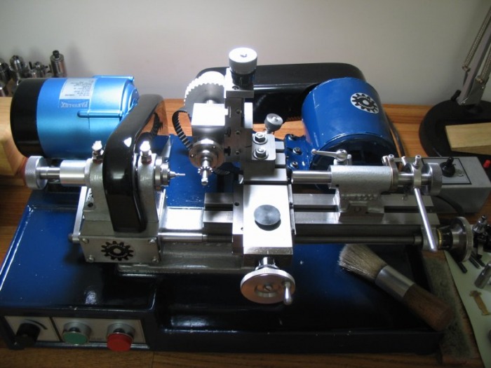
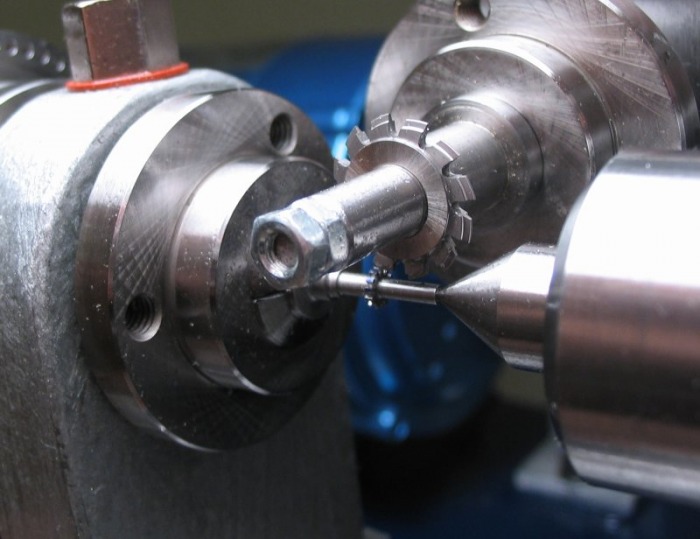
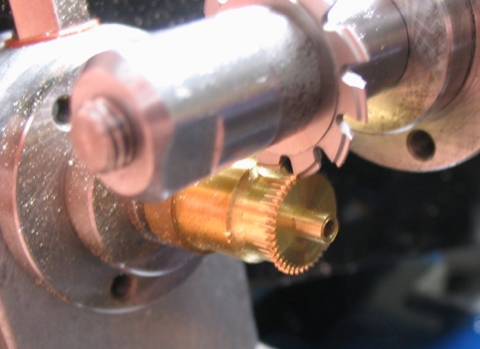
The lathe is then setup for milling the leaves, indexing was performed using the headstock pulley (60/5 = 12). The speed reduction pulley was installed and the layshaft set to mid-range speed, this results a cutter speed of 690 RPM. The full diameter of the pinion leaves is coated with a blue marker, this allows one to clearly monitor the cutting progress.
 |
 |
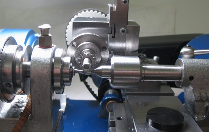
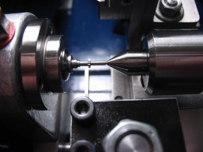
Tailstock support was used, and if you notice, the tailstock base is moved against the cross slide, this acts as a stop when retracting the cutter.

 |
 |
Milling was done in four passes, three of 0.2mm depth, and a final pass at full depth, determined in situ by observing the landing (topping of the leaf with the cutter).
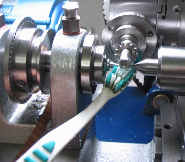
Note: A couple drops of oil is applied with each pass, and an old tooth brush works well at brushing the teeth clear of swarf and oil.

First Pass
Second or Third Pass
With the milling complete, the cannon pinion is then parted off.
The cannon pinion is then reversed into a 1.7mm collet, and the base faced to the final thickness, with very light cuts as to not deform the leaves.
The cannon pinion is then broached to friction fit the setting arbor. It is left so that a tight fit is found before fully seated, that way it can be staked fully home and will therefore have a very tight fit. The cannon pinion should never slip on the setting arbor, this is the opposite of what is normally found in keyless set watches.

Minute Pinion
The minute pinion is made much the same way as the cannon pinion. 6mm O-1 drill rod was turned down to the pinion leaf full diameter plus 0.05mm, and a small 1.5mm by 0.6mm boss was turned that will friction fit the minute wheel. It has ten leaves, so only the cutter needs to exchanged and otherwise the milling setup can be reused.

The milling was completed in four passes as before.
 |
 |
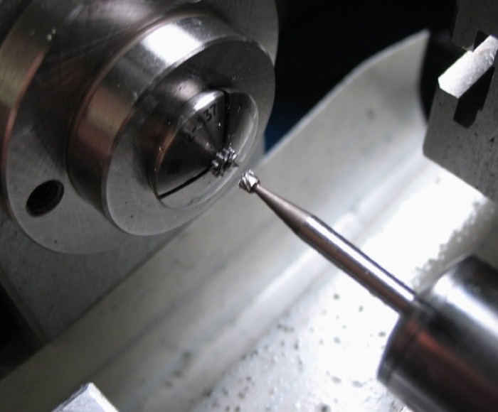
The pinion is parted off and reversed into a 1.50mm collet and faced and then countersunk with a 90 degree setting bur in the tailstock. This will form an oil reservoir for the finish component.
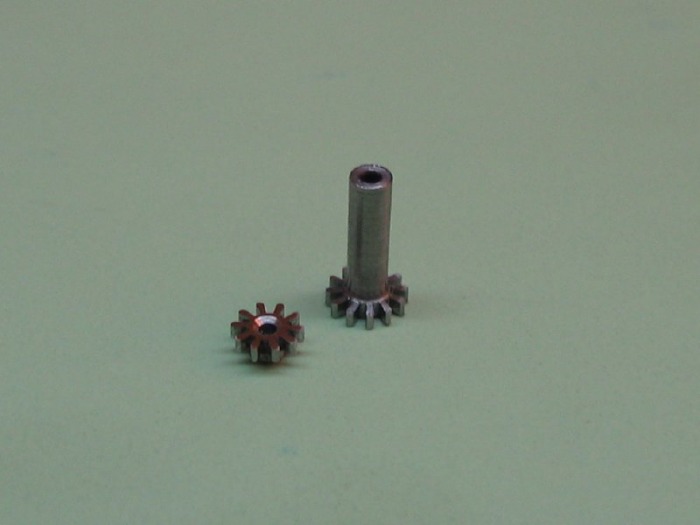
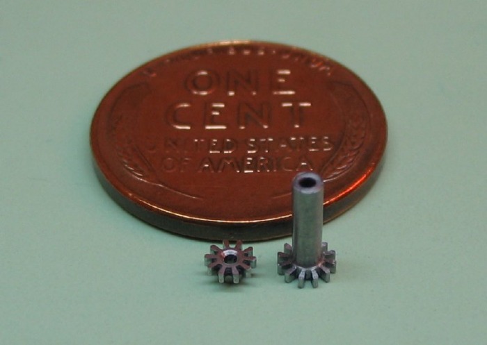
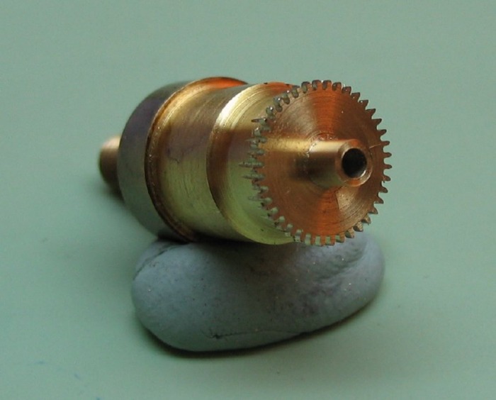
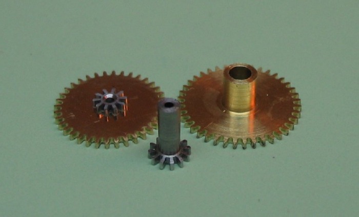
The faces were lightly polished on a glass plate with emery paper, and the pinions can be seen below, one photo is next to a U.S. penny (¾ inch or 19.05mm).
 |
 |
Hour Wheel
The hour wheel is made much the same way as the minute wheel, starting with ½ inch 360 brass rod, the pipe is turned and then parted off. The pipe is held in a collet to then face the bottom to the required thickness.

The wheel is then mounted to a super-glue arbor. It is drilled, broached with the previously made 1.7mm broach (Motion Work I), the pipe given a light cut to ensure concentricity, and the full diameter turned.
The lathe is setup for gear cutting, the G2 index plate has counts of 80 and 72, which can be used to index the hour wheel (40) and the minute wheel (36), by counting every other hole.
 |
 |
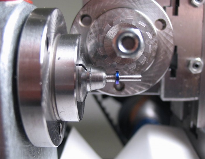
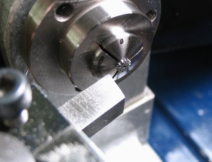
Although the full depth is calculated (0.6125mm), the actually cutter depth is determined in situ, by observing the resulting tooth tips, or landing. If the wheel is first coated in layout blue, the resulting tooth tip will appear as a diminishing blue line, full depth is when only a sliver of blue line remains. Photo below is after a few trial cuts to determine this depth (remember that the cutter makes the tooth space, so two cuts are needed to observe a complete tooth).
Once the full depth is found, the remaining teeth are cut in one pass, running the cutter at maximum speed. A procedural note, the motor is shut off after passing through the wheel, and then retracted. This way the tooth is not deformed or mis-cut by the cutter while retracting. This is not always pointed out in texts, but is sound advice, I first heard it in William Smith's video on wheel and pinion cutting.
After which the wheel can be removed from the arbor using a butane torch to melt the glue. It is washed in acetone to remove the residue.
 |
 |
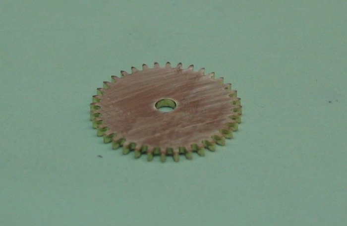
Minute Wheel
The minute wheel is made from ½ inch 360 brass rod, the end is faced and a disc is parted off. The faced side is adhered to a super glue arbor. This type of arbor is the same as a wax-chuck found in classic texts, and as I use them for other jobs, they should look familiar if you have read other pages on this site. A fresh one was made from a piece of scrap brass rod to fit the threaded 5mm collet, turned to slightly less than the root diameter of the wheel, the end faced, drilled and then grooved to assist in holding the glue.
The teeth are cut in the same manner as the hour wheel.
Obviously, I did not turn the glue arbor down far enough ...

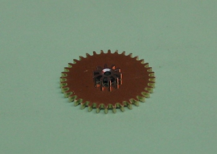
The boss on the minute pinion was turned to 1.50mm. The minute wheel was broached using the 1.48mm jewelling broach in the staking tool. The pinion was then driven into position with a staking punch.
Depthing
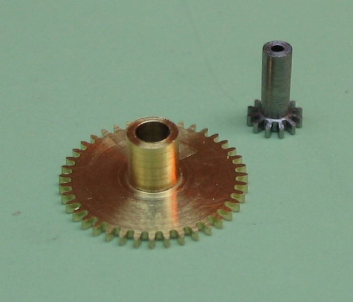
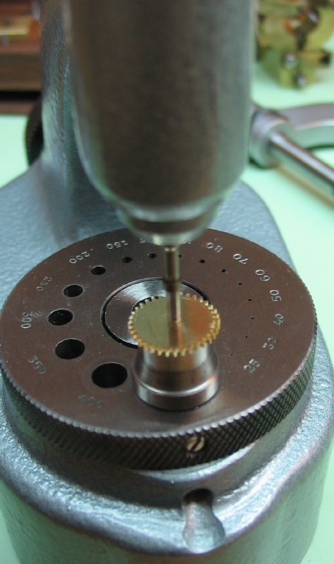
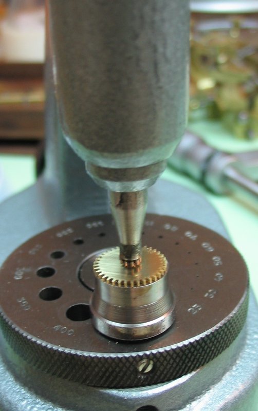
The finished components can then be depthed together and the location for the minute wheel can be determined. The parts are mounted together in the depthing tool, and the best pitch is found for all four parts as one.

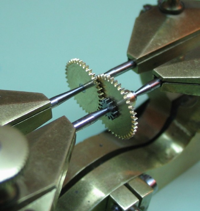 |
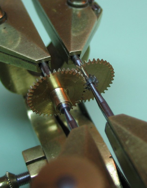 |

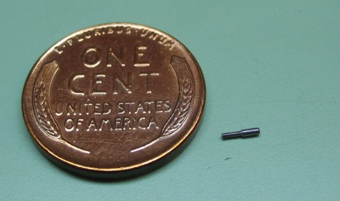
The minute wheel will run on a small arbor or stud. The minute pinion was drilled 0.70mm, so the stud was made to fit this and with 0.6mm threads to screw into the mainplate. The plain 0.7mm portion was finished with a hard Arkansas slip stone to give a very smooth action with the minute wheel.
I am planning to make the motion work removable, in the event I complete the retrograde motion work, that way either system could be used, perhaps even interchangeable with a separate dial.

The third wheel recess will help determine the confines for the minute wheel. A suitable position is found on the arc scribed previously, and the position center punched on the staking tool, chamfered, center drilled, drilled, and tapped 0.6mm. The stud can be filed to be flush with the center wheel recess on reverse side of the mainplate.
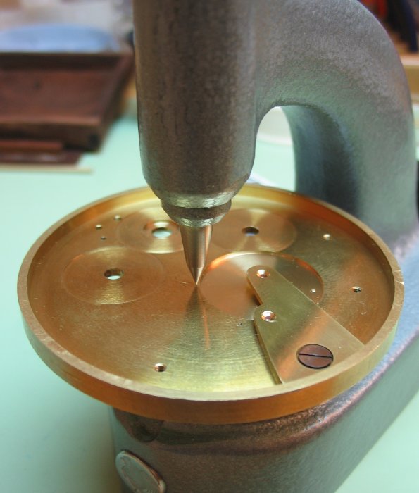
Prick punch on staking tool
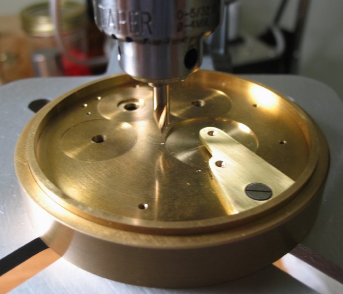
Center Drilling
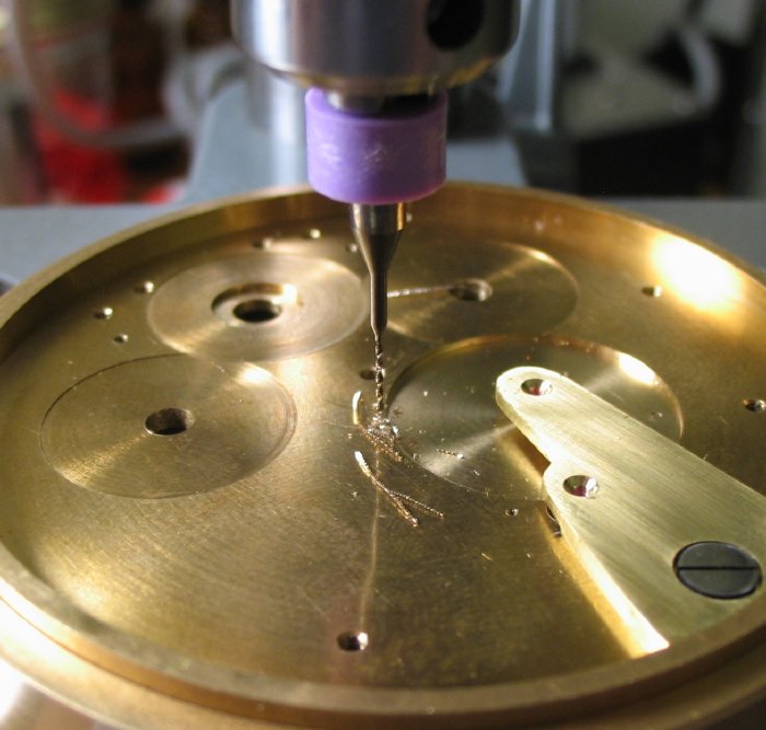
Drilling

Tapped and stud fit to mainplate
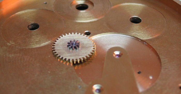
Minute Wheel in its final location
