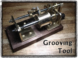
Described on this page is a device for cutting the groove in a winding barrel. The design is an adaptation of John Wilding's fusee grooving tool described in "Tools for Clockmaker and Repairer - How to make and use them." The tool described here is essentially the same, but uses a different pitch leadscrew and a variety of other small changes to suit materials, tools, or hardware available. Mr. Wilding notes that the design is originally based on that of John Stevens and was described in the February 18, 1972 issue of Model Engineer.
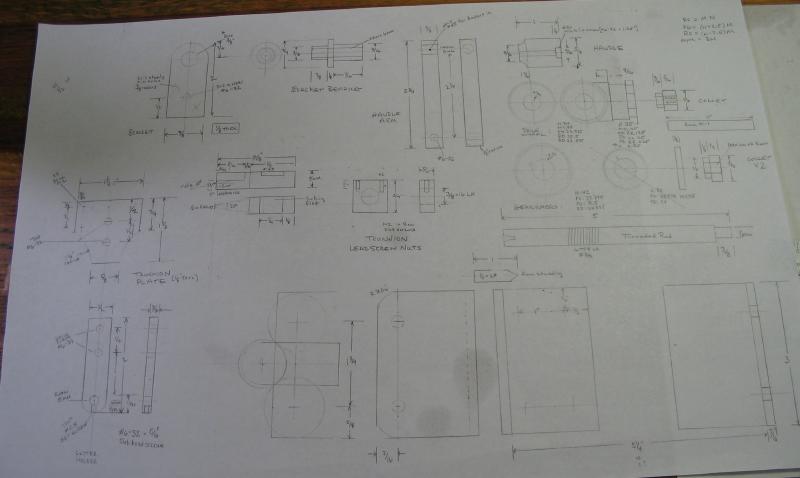
Although most of the dimensions are the same, it is helpful to sketch out everything out which helps in deciding on the starting material and tools needed.
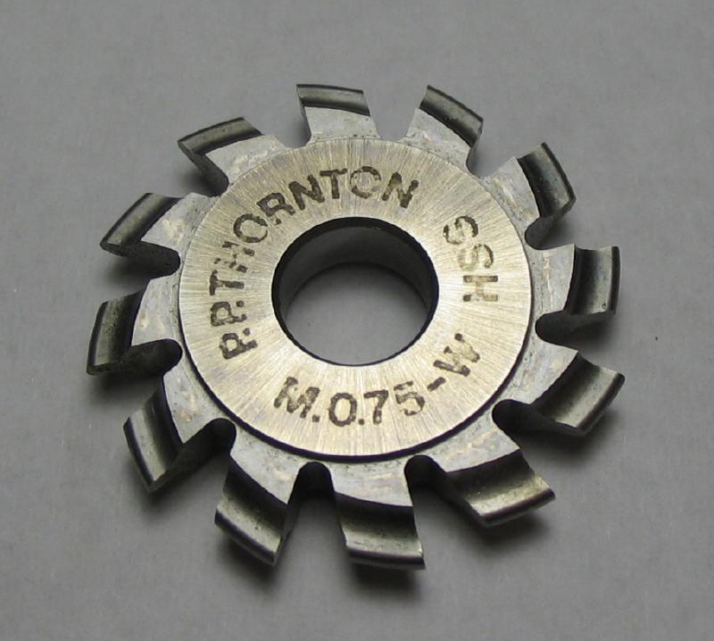
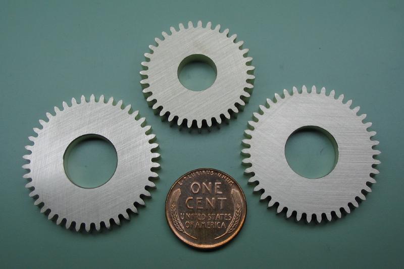
I started with the gear work, which are based on a 0.75 module P.P. Thornton wheel cutter. Mr. Wilding's design uses a 1.0 module cutter, but he suggests 0.75 for those working on a smaller lathe, such as the Unimat 3. Just a note to those that may be interested, the same instructions for making the fusee grooving tool are included as an Appendix to Wilding's other book titled "Machining and Constructing a Scissors Clock," which, of course, requires making a fusee, and also uses a 0.75 module wheel cutter and the work was carried out on a Unimat lathe, although a screwcutting lathe attachment is described in the main text of that book. But the point being, whatever size cutter is available will likely do. In his words, "Although some readers may think that this is all a lot of work in order to carry out just one task, I have described the tool simply to show how the work can be accomplished in the absence of a screwcutting lathe."
The device uses a single drive gear and a pair of identical driven gears that are fixed to either the leadscrew or to the arbor of the work being "grooved," i.e., the arbor of the winding barrel in this case. To keep the wheel diameters/ratios about the same, the tooth counts need to be adjusted for the switch to 0.75 M and this decision was also influenced by the hole counts available on my dividing plates for the Cowells lathe, and the exact ratio is not critical.
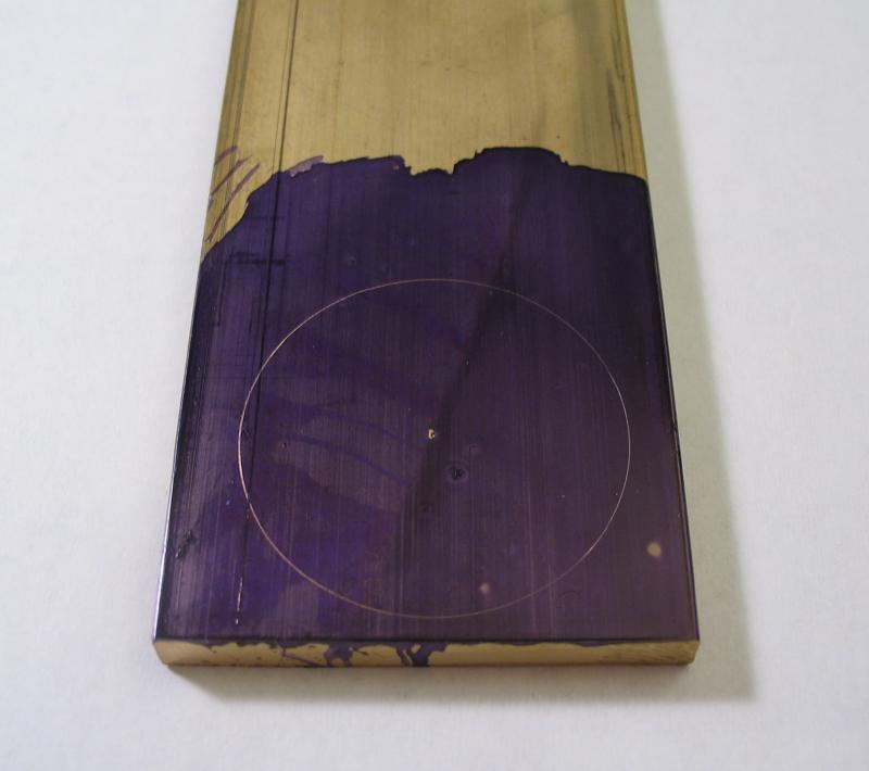
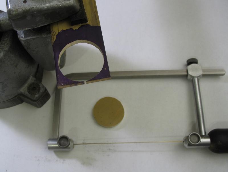
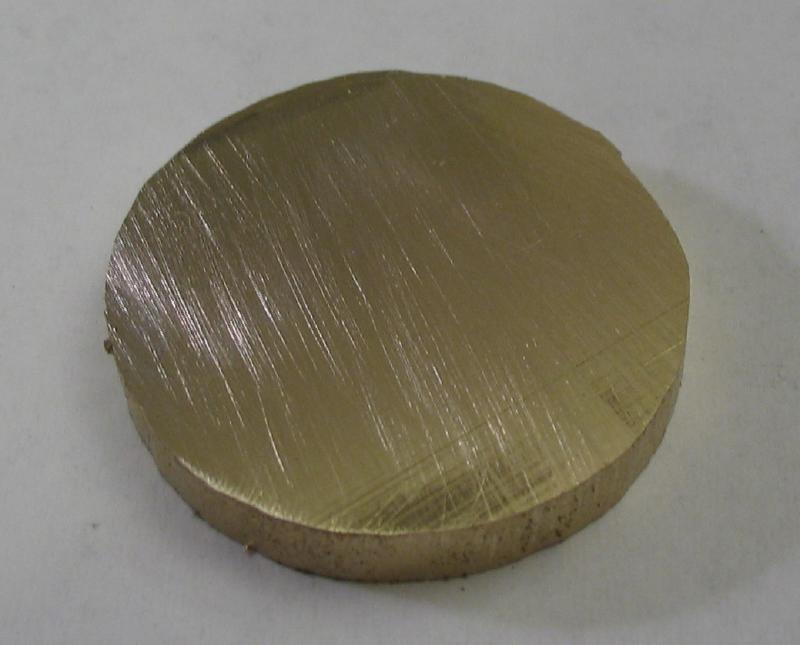
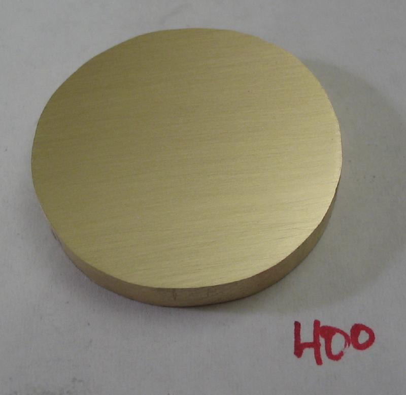
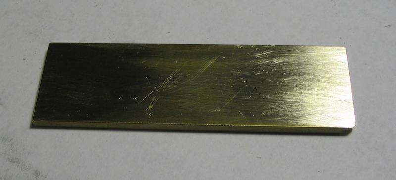
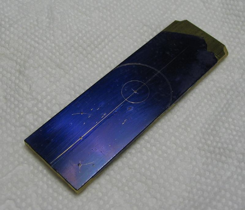
The drive wheel was made from 3/16" brass plate. The full diameter was scribed from a center punch mark and then sawed out using a #6 sized jewelers saw. The surface of the bar is slightly uneven, which was filed smooth on one side and then rubbed on 400 girt emery paper on glass to give a fairly flat finish.
|
|
|
|
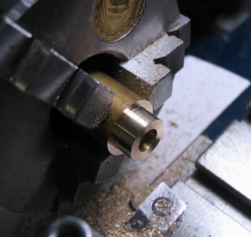
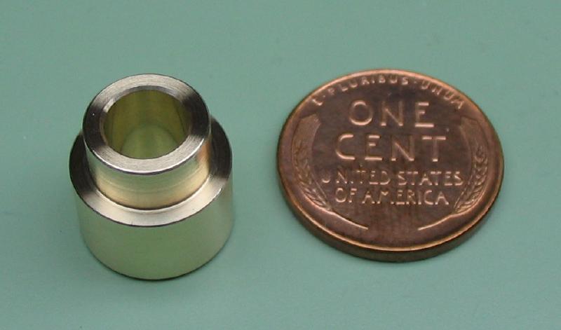
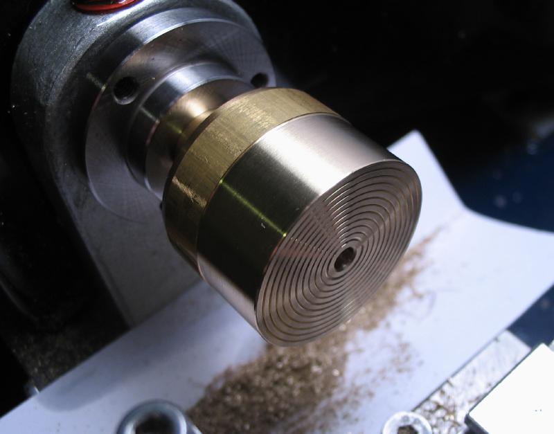
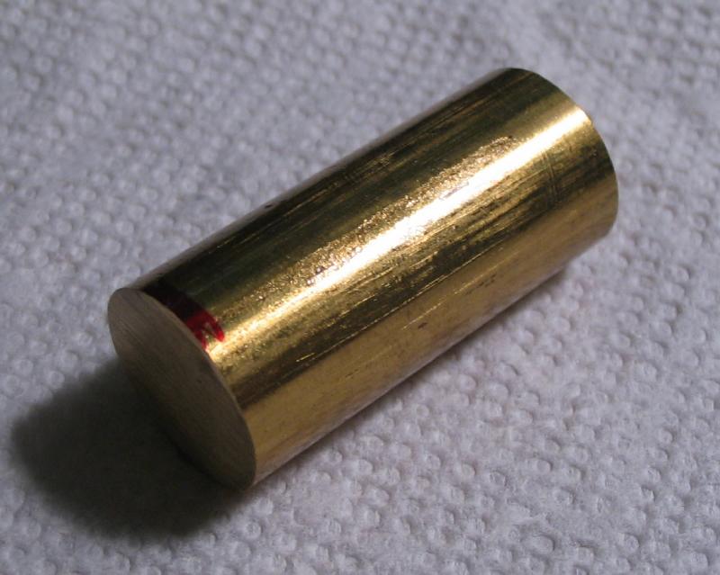
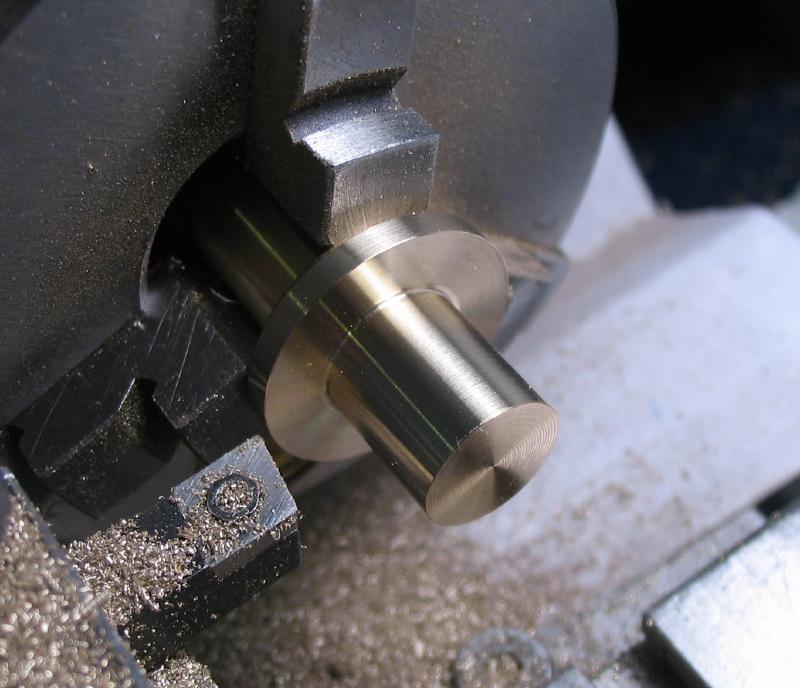
A cement chuck was made from one inch brass rod following the same method described on another page. It was turned down for about 10mm to a diameter of 28.6mm, which is just under the calculated root diameter of the wheel teeth. It was drilled with a 1/8" spotting drill for a short clearance hole. The face was turned and grooves formed that are for retaining glue.
|
|
|
|
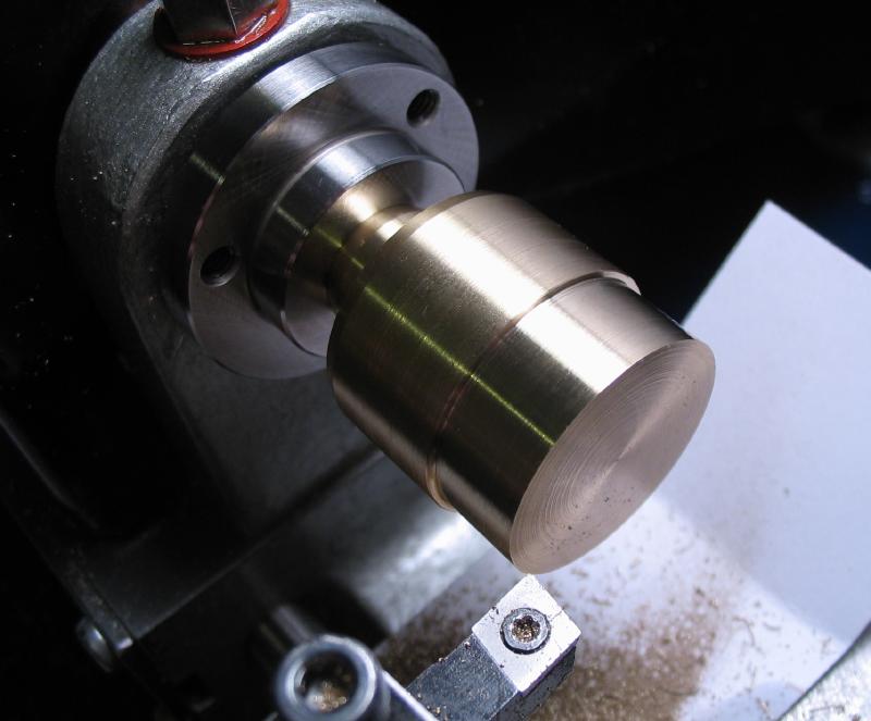
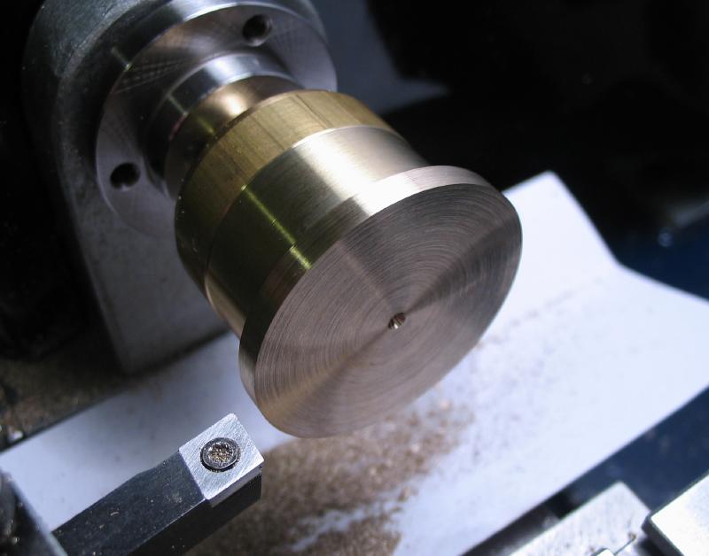
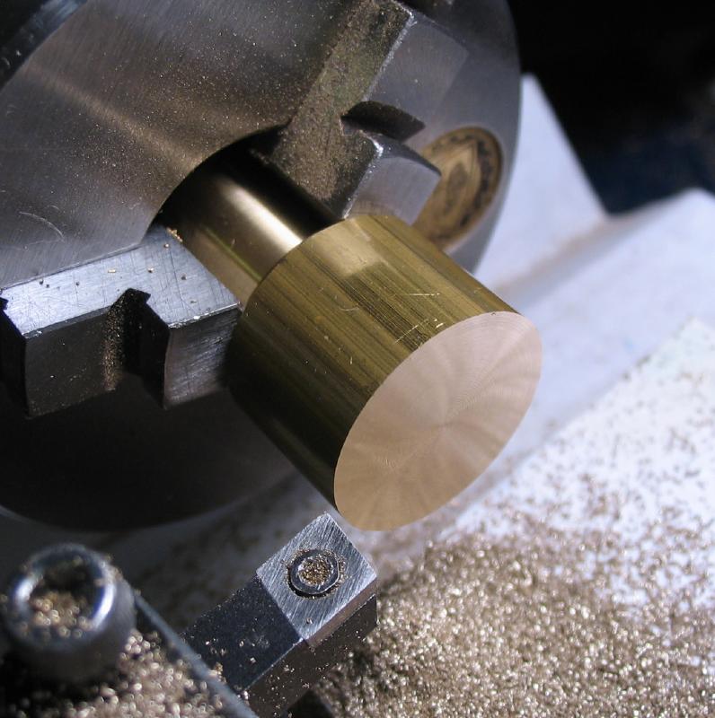
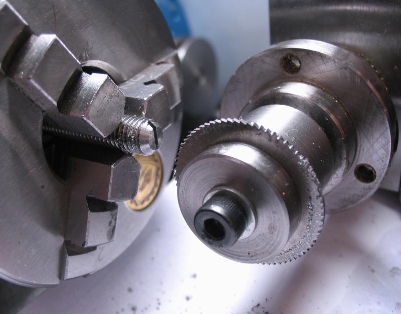
With some super glue spread on the face, the wheel blank disc was attached with the aid of the tailstock center, which is locked in place while the glue cures. The disc was then turned as close as measurable for the full wheel diameter, 28.13mm, and faced. The slight uneven surface of the brass stock can be seen in the photo, but was easily turned flat.
|
|
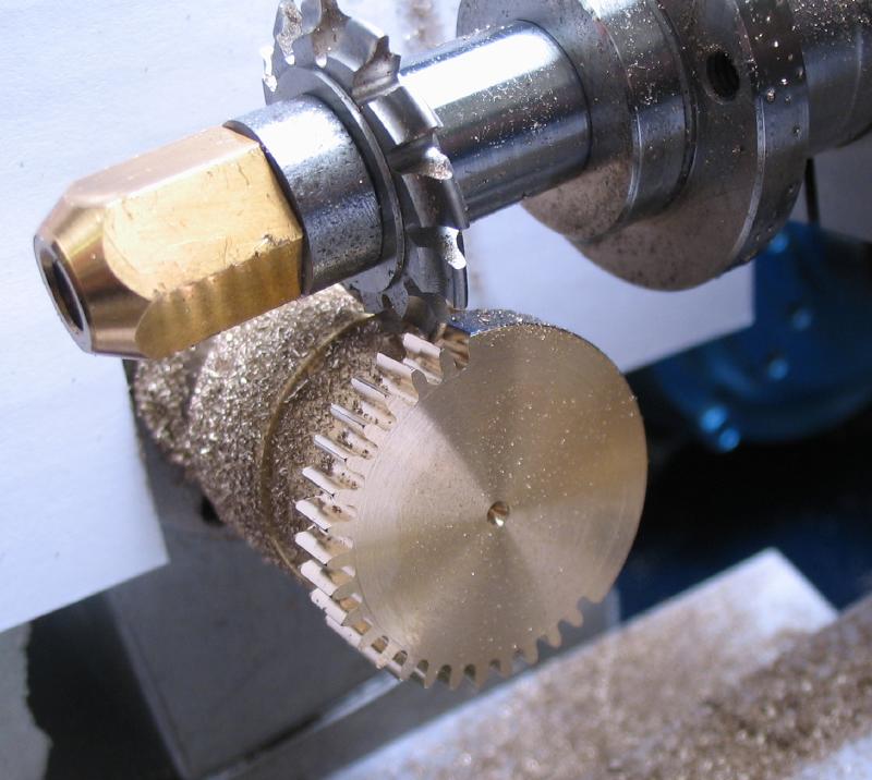
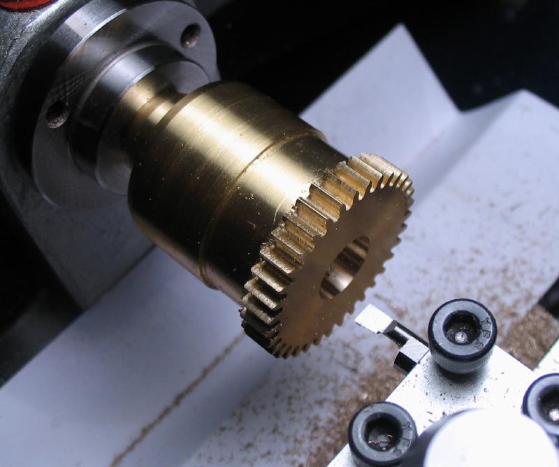
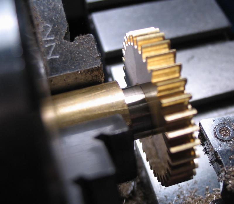
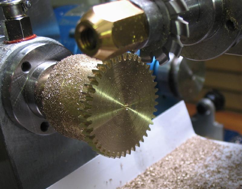
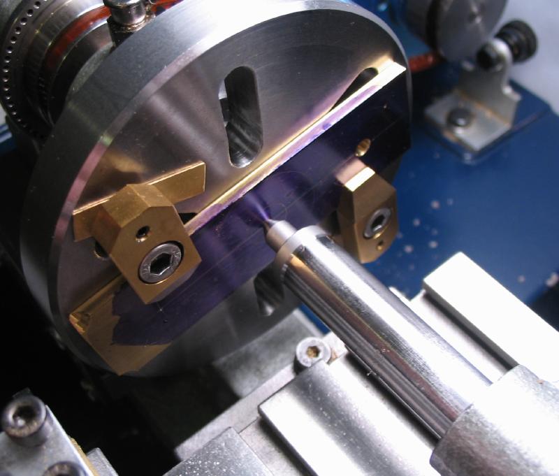
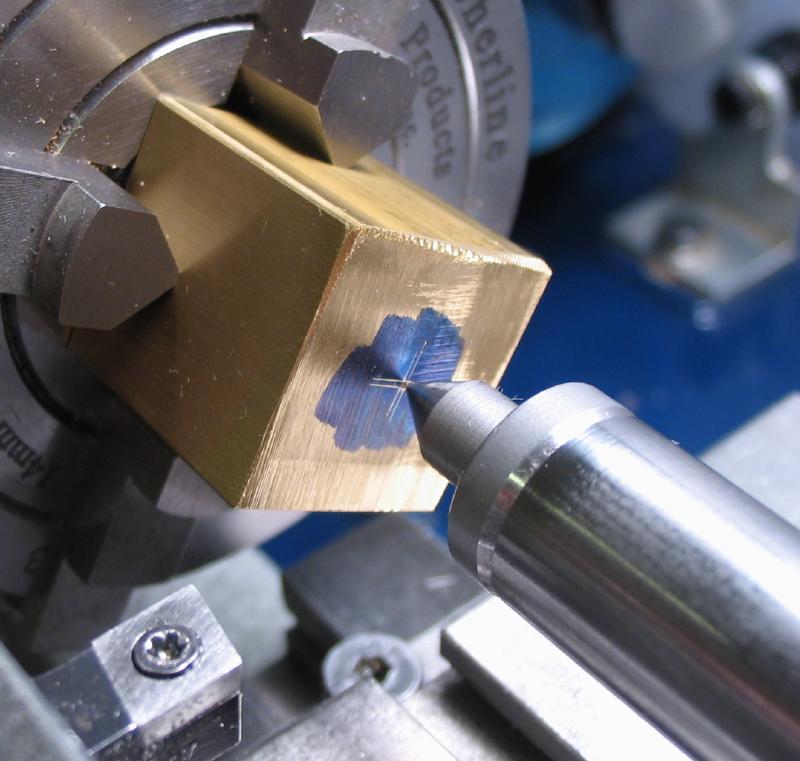
The milling spindle was set up in the vertical slide and the cutter aligned with lathe center. A dividing plate was installed on the headstock, using the 70 count plate to provide the 35 positions for cutting each tooth space. The perimeter was colored blue with a Sharpie and two adjacent positions cut, lowering the cutter until only a thin blue line remains at the tooth tip. The remaining tooth spaces were then cut at full depth and at maximum cutter speed. I turn the cutter off while backing out and moving to the next position.
|
|
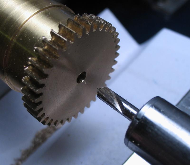
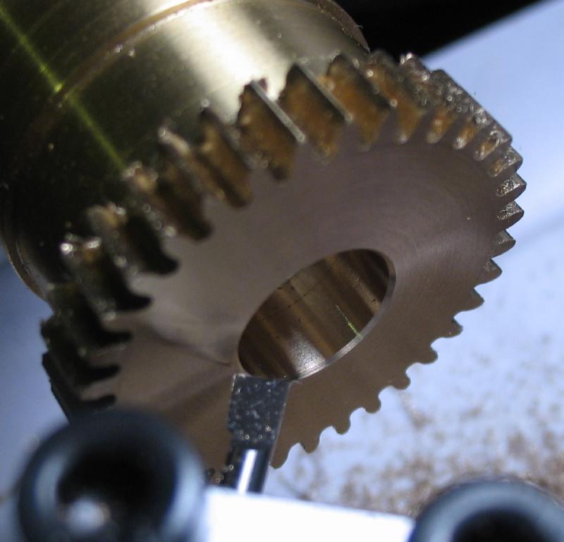
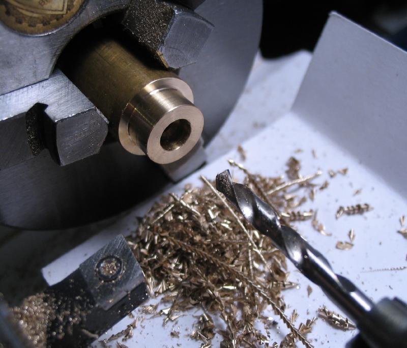
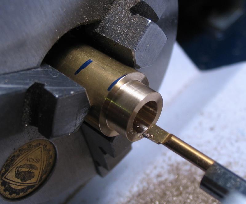
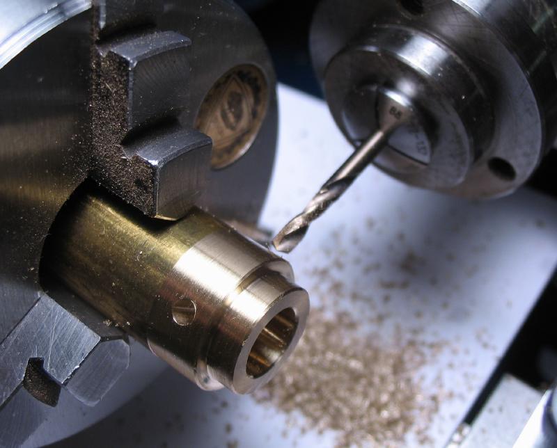
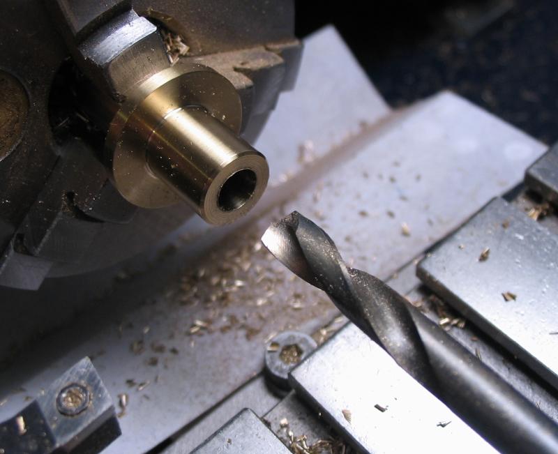
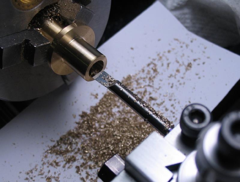
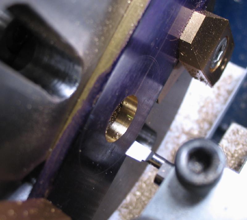
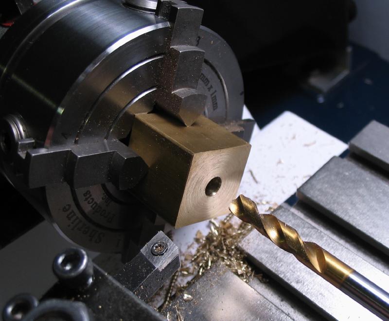
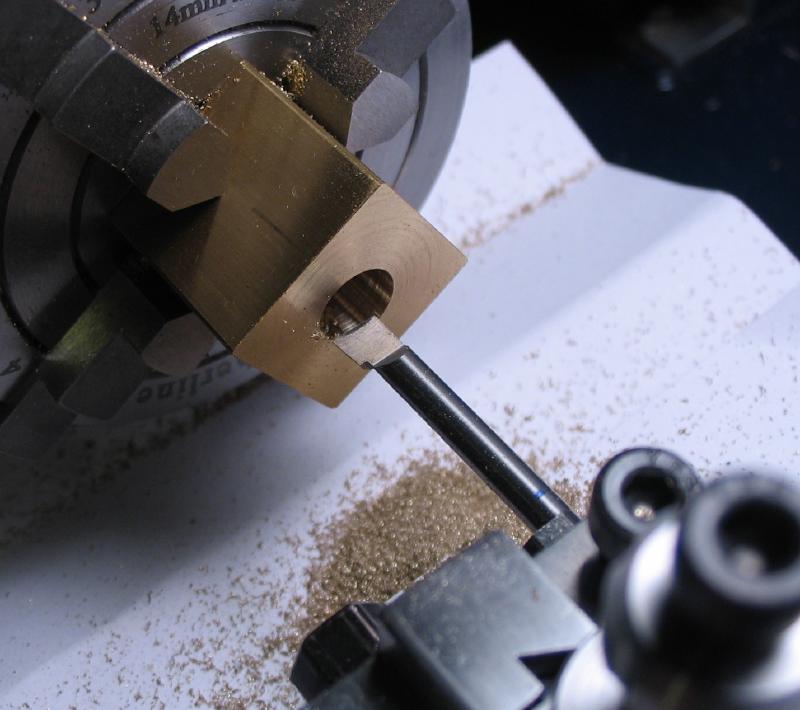
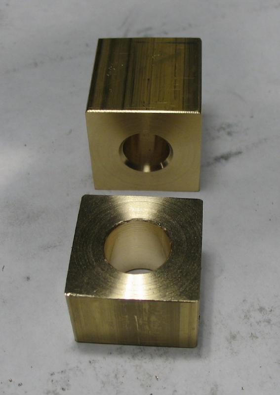
An advantage of the cement chuck method is that all the steps of machining the wheel are carried out without the need to 're-chuck,' so the work remains on center. After cutting the teeth, the wheel was drilled through and bored open to about 9.5mm (the collet will be turned to fit). The hole was countersunk slightly to remove the sharp corner.
|
|
|
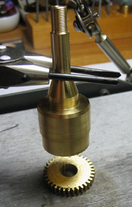
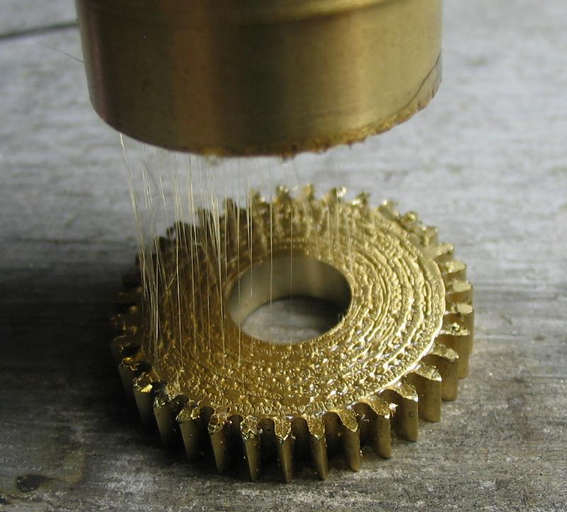
The arbor was held in the soldering station while heating with a butane torch to melt the glue and free the wheel.
|
|
The faces were smoothed with various grit emery papers and shown here after 800 grit, if I recall correctly, and washing with soap and water; an old toothbrush is great for brushing out the teeth.
|
|
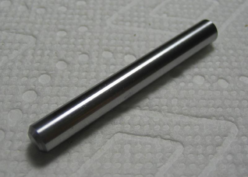
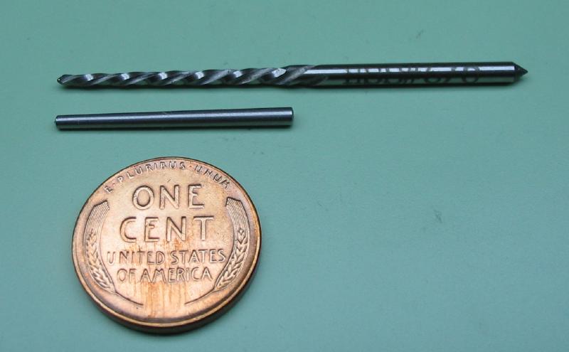
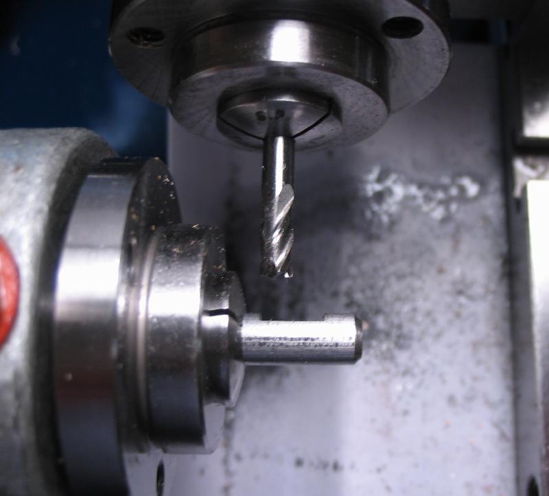
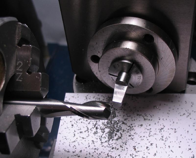
The drive spindle is made from a roughly 2-1/4" length of 1/4" O1 drill rod. The ends were faced and chamfered 45 degrees. The surface was smoothed with 800 grit emery paper to remove scratches and small burs since the rod will both friction fit the wheel and run in a bearing, so a smooth surface should be helpful. The spindle was needed before making the collet to the drive wheel, since it will be bored for a very snug fit to the spindle.
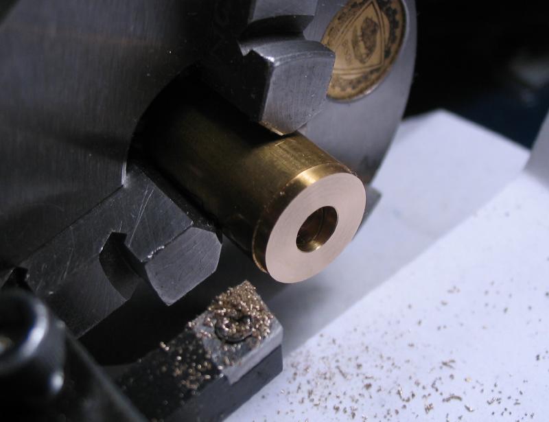
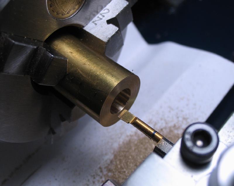
A collet for the drive wheel was made from a piece of 1/2" diameter brass rod. It was found in the scrap bin, and was already drilled and turned a bit, but these are machined away in the following steps. The rod was faced and turned for a tight fit to the bore of the drive wheel (about 9.5mm). Turning was discontinued once the wheel first started to fit. The rod was then drilled 1/8" to admit a boring bar (BB120500). The hole was bored to a depth of 1/2" and to a diameter that was a very tight fit to the spindle.
|
|
|
|
|
The work was extended out in the chuck, using the tailstock center to help keep the work centered. The larger diameter of the collet was turned (just turned true), and then parted off. I used the tailstock center while starting the parting, since any extra rigidity helps, but the center withdrawn when almost through. The work was reversed into the chuck and the parted face turned and the bore countersunk and corner chamfered.
|
|
|
|

|
|
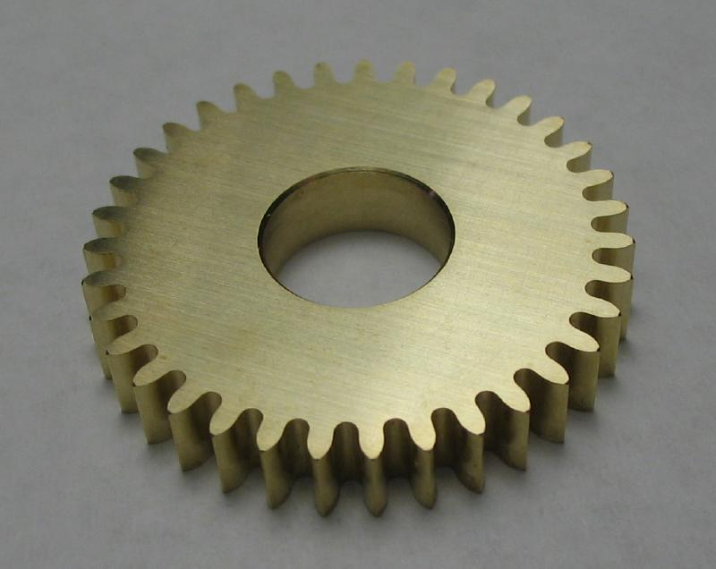
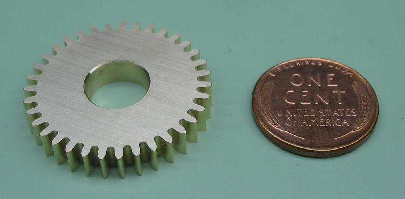
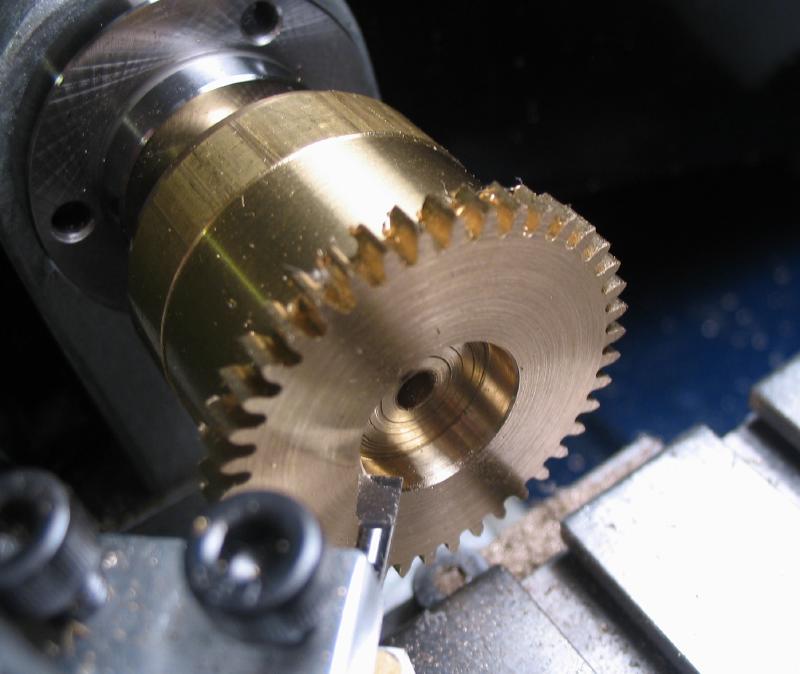
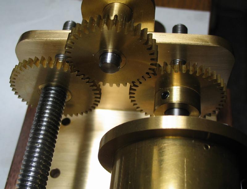
While on the subject of making wheels, two additional wheels are needed, referred to as the 'gear wheels.' They will match each other and are driven by the drive gear above, so will both turn at the same rate. They were made with the same 0.75 module cutter and with 42 teeth the wheels should be 33.375mm in full diameter [(t + 2.5) x M]. They were started from 1/8" brass bar and made in the same manner as above for the drive wheel. The diameter was measured with a caliper, and left at 33.38mm. Another cement chuck was made from 1-1/8" diameter brass rod to hold the wheel blanks, I hope to eventually have made enough of these chucks so that someday the diameter needed is already on hand. The chuck made above could have likely been used, but for maximum support it should ideally be just shy of the tooth root diameter to clear the cutter as it passes through the wheel blank. The tooth depth is 2.25mm (3 x M) making the correct root diameter 28.875mm [(t - 3.5) x M].
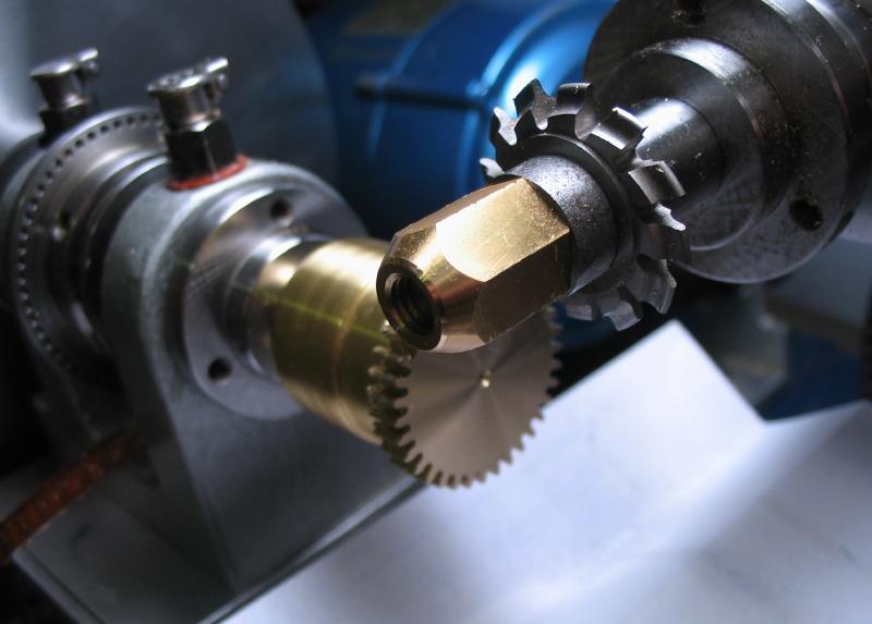
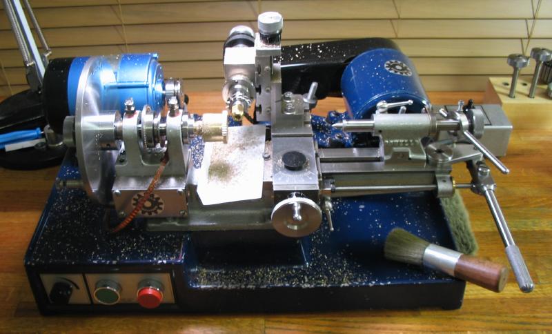
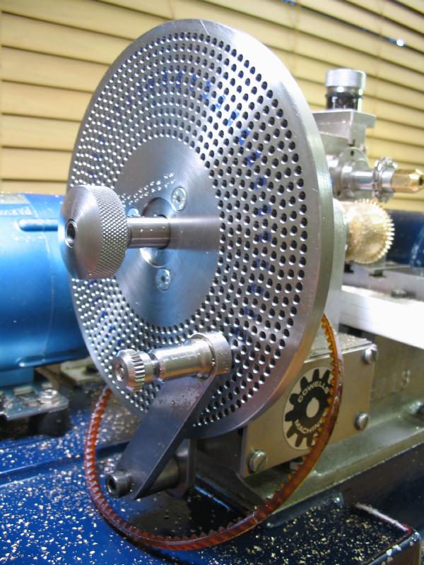
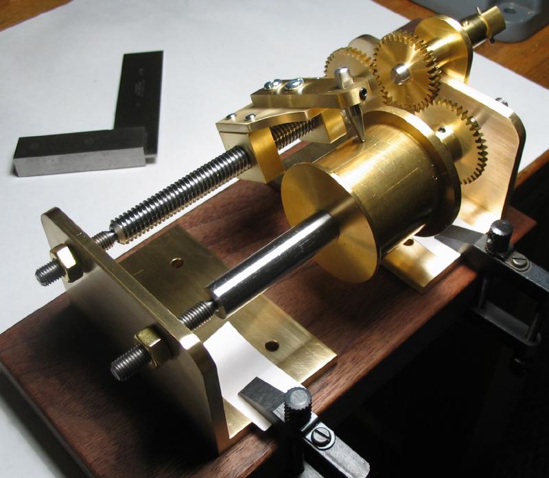
A couple photos of the whole wheel cutting setup on the lathe is also shown, although it is the same as on other pages of the site. Everything still has a coating of brass chips; the cutter was run at full speed and at full depth and using a lever feed, which worked very well but throws chips everywhere. The 84 count circle of the dividing plate was used and marking every other hole with a Sharpie pen is helpful later on when losing count. The Sharpie ink easily wipes off afterwards with some alcohol or acetone.
|
|
|

|
|
|
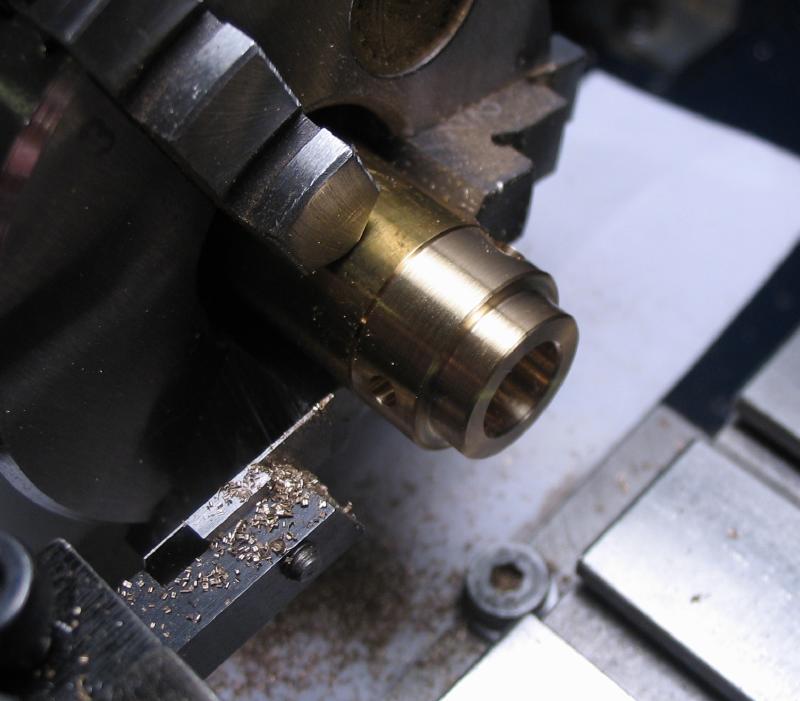
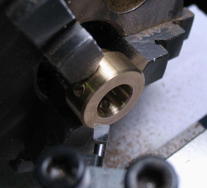
The two gear wheels were bored 1/2" and chamfered before detaching from the chuck and then given a quick rub on emery paper to clean up.
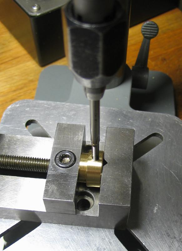
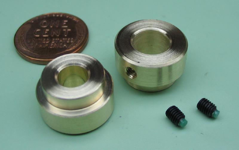
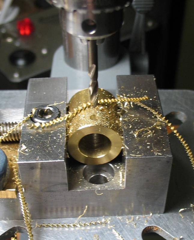
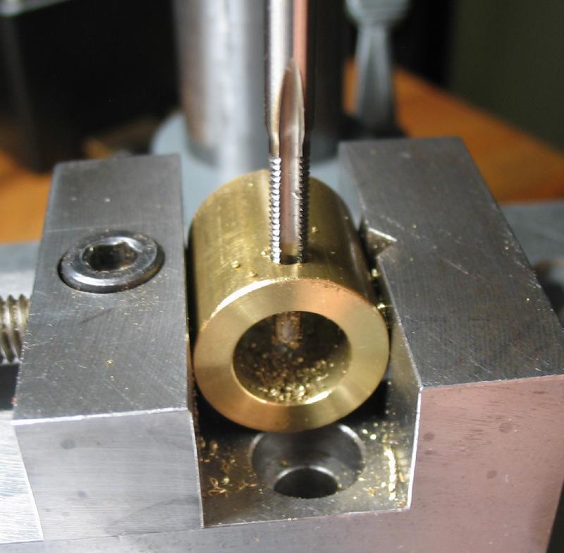
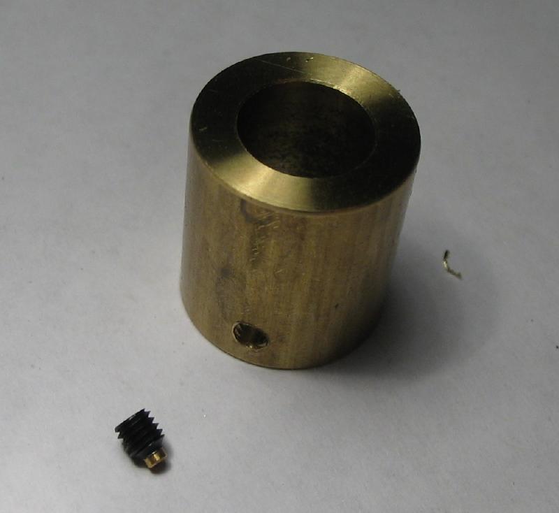
Collets for the gear wheels were made from 5/8" diameter brass rod. One is bored 8mm to fit the arbor of the winding barrel and equipped with two set screws set 120 degrees apart. The M3 set screws have nylon tips to protect the arbor. The other collet is bored 6mm to fit the leadscrew and will be a permanent fit, so set screws omitted. The steps for production are similar to those above for the drive wheel collet, except for drilling and tapping for the set screws.
|
|
|
|
|
|
The spindle bearing was made from 3/4" diameter brass rod. It was a roughly 30mm length and faced on one end, center drilled, and then turned to about 7/16" diameter for 5/16" length. The corners were chamfered, and the work then reversed in the chuck to turn the other end.
|
|
|
|
The other end of the spindle bearing was reduced to about 3/8" diameter for 7/16". I do not have a 3/8" reamer or even one close, so the bracket will be bored later to fit the bearing, rather than turning the bearing to friction fit the bracket.
It was drilled through with a 5.5mm bit, this was to pass a long boring bar. The hole was bored to slip fit the spindle rod.
|
|
|
|
|
|
A countersink drill was use to form an oil sink in shaft of the bearing. This was carried out while mounted in a vise on the vertical slide.
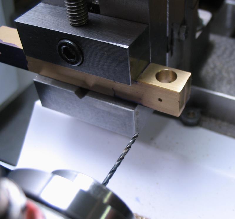
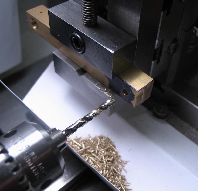
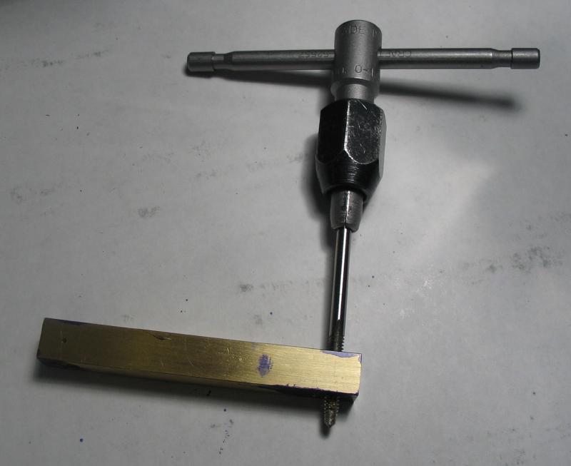
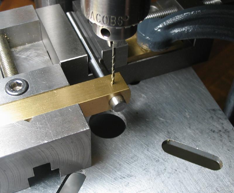
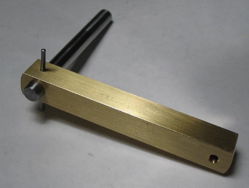
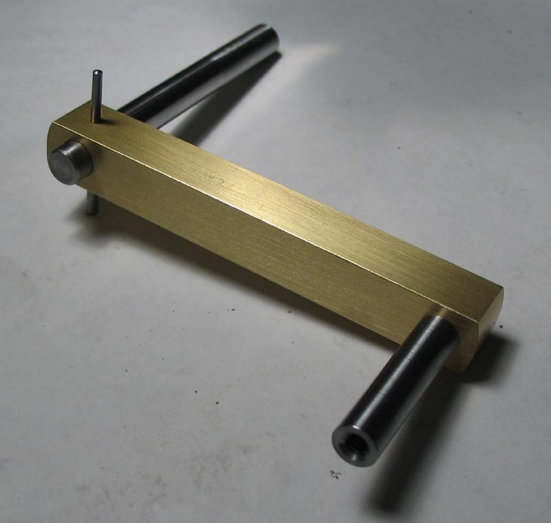
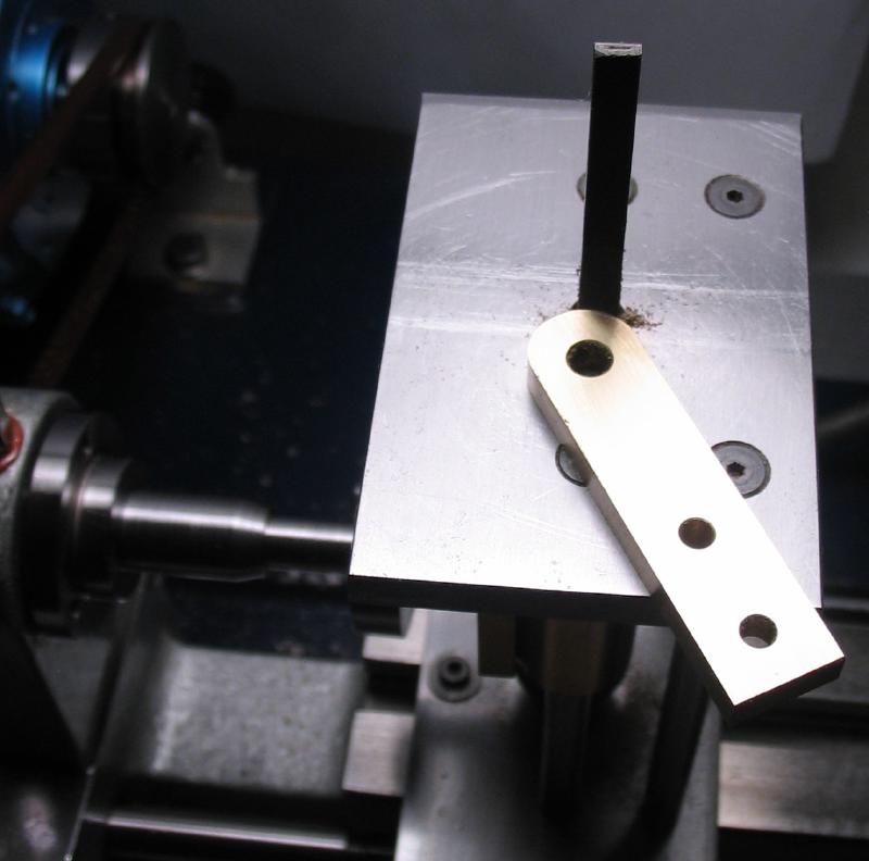
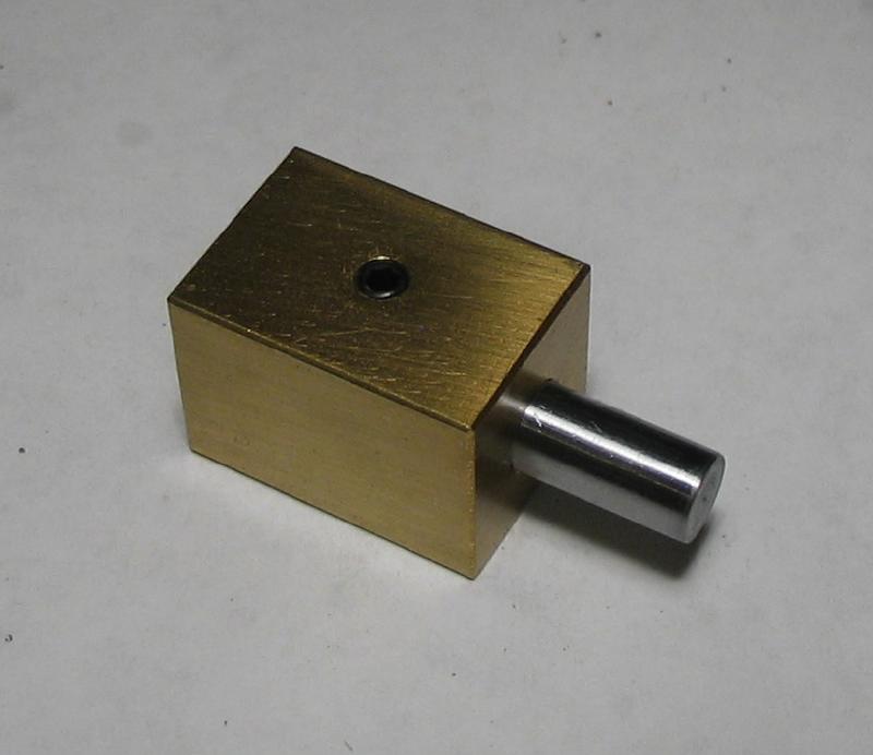
The crank arm is made from 3/8" square brass bar. Since the surface is fairly rough, it was filed and smoothed on 400 grit emery paper prior to laying out dimensions. One end of the bar is drilled and reamed 6mm for the drive spindle; I did not have a 1/4" reamer on hand, so the spindle will need to be turned to fit. It was cross drilled 3/64" in the perpendicular and will be reamed for a tapered pin later, and may have better waited to drill then as well. The opposite end of the bar was drilled #36 and tapped #6-32. The ends were filed to leave a roughly 1/2" radius.
|
|
|
|
|
|
|

|
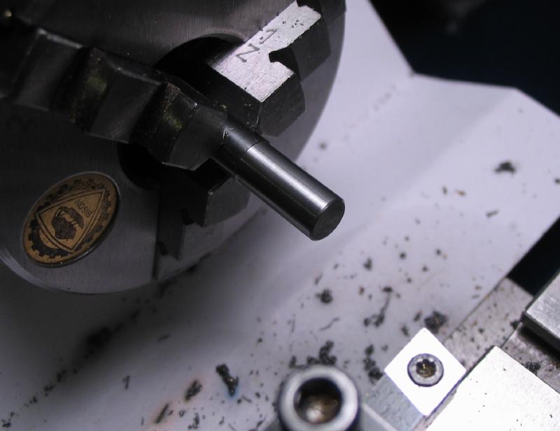
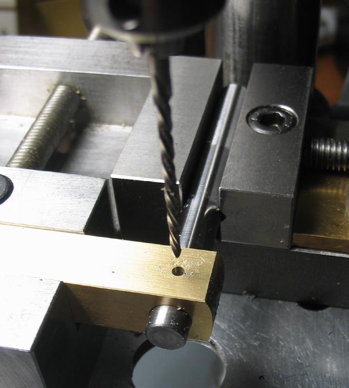
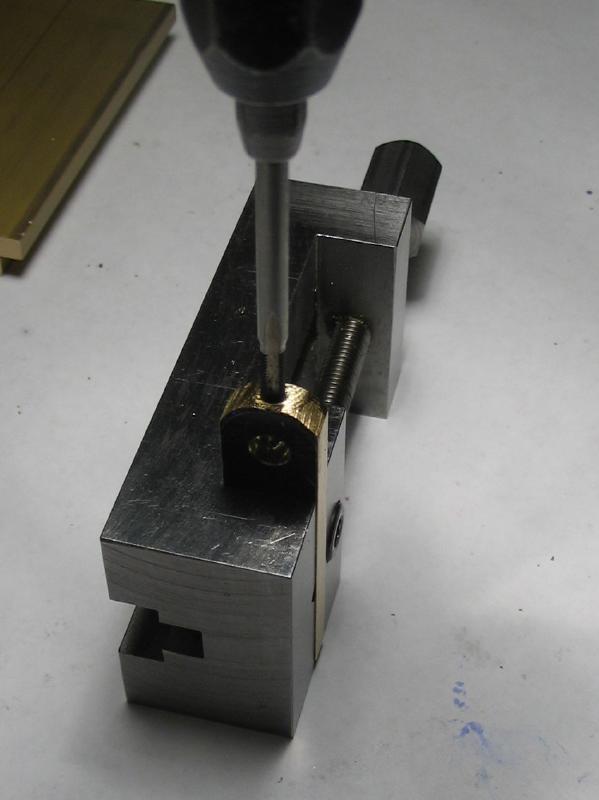
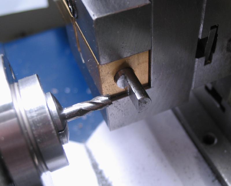
The spindle was turned down to fit the 6mm hole in the crank bar above. This can be a light fit so that disassembly is relatively easy. Turning was discontinued when tight and an oil stone used for the final finish and fit. The spindle and crank arm were assembled and each piece held in a vise, which was then clamped to the drill press table. The 3/64" hole was transferred to the spindle rod and the hole then reamed with a #6-0 taper until the matching steel taper pin could be inserted about half way.
|
|
|
|
|
|
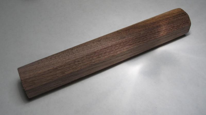
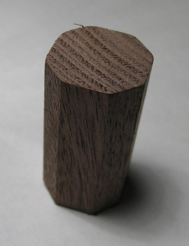
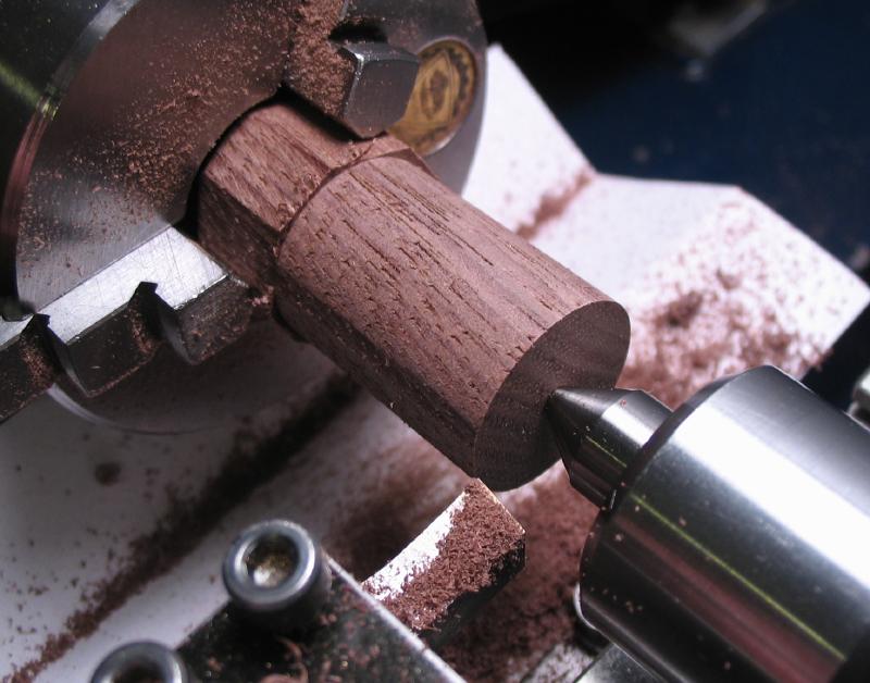
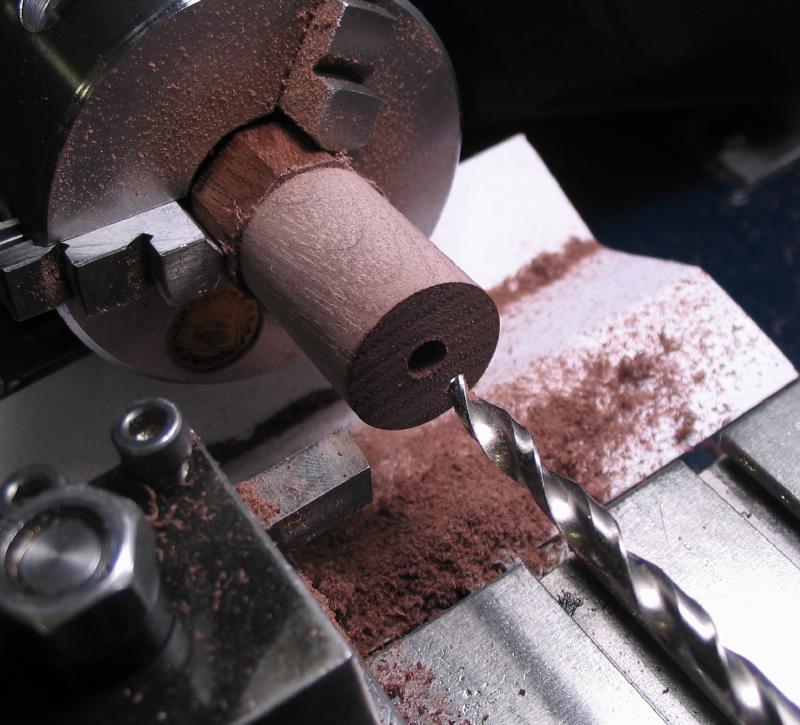
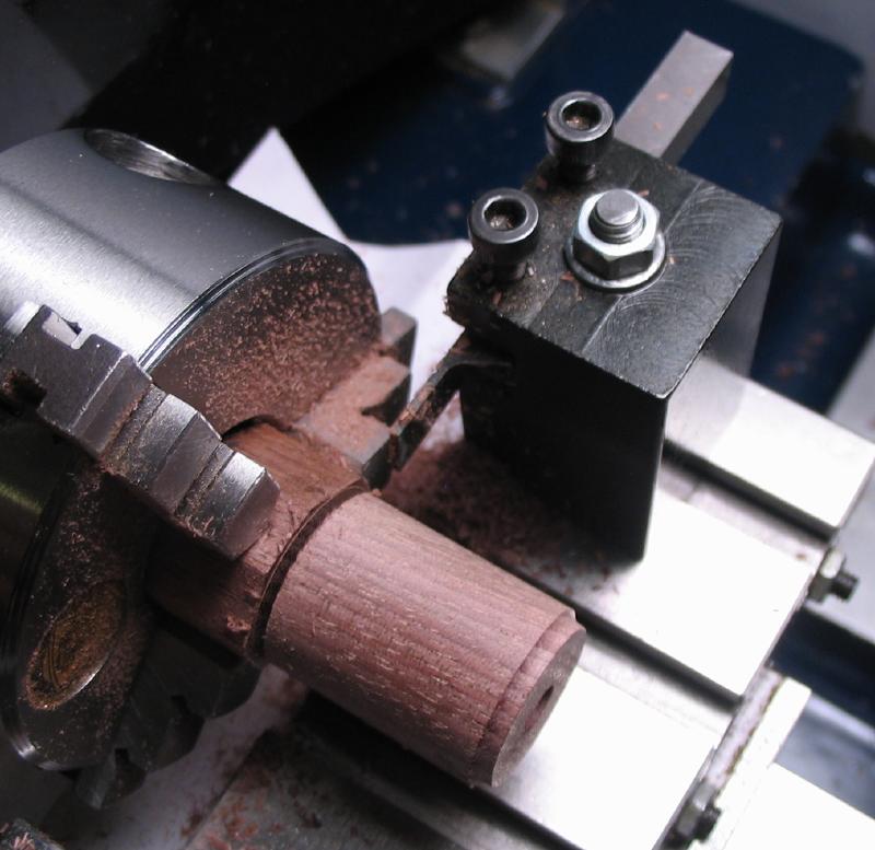
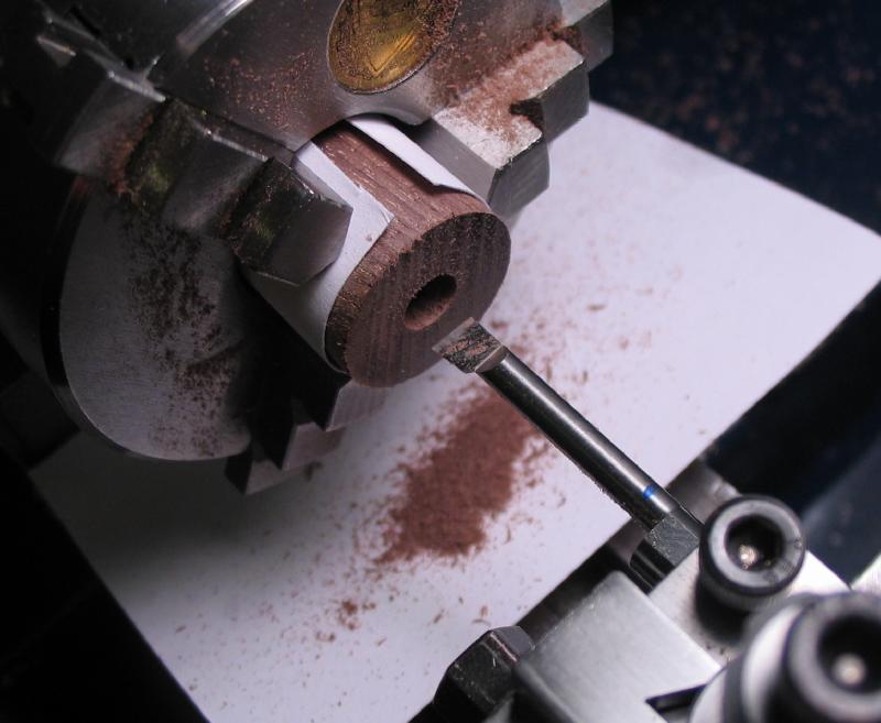
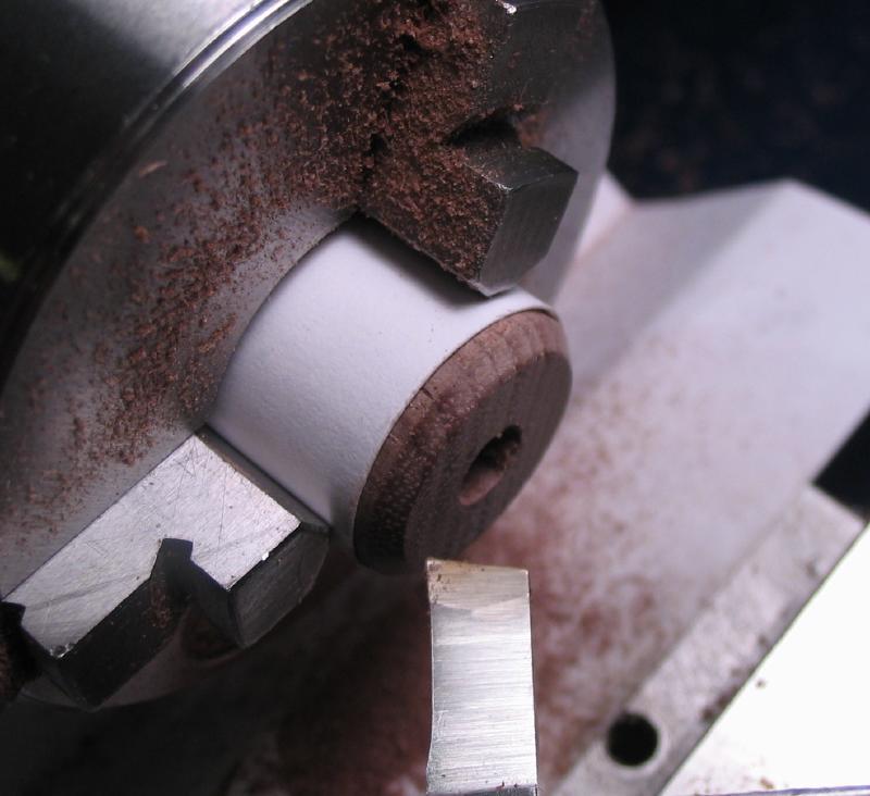
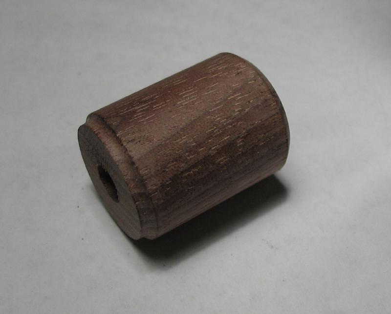
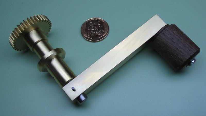
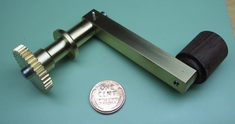
The handle was made from a 3/4" width walnut "pen blank." Although usually found as square stock, this vendor had octagonal stock, which reduces the amount of material to turn away to make round. A length of about 36mm was sawed off and mounted in the 3-jaw chuck, finding a relatively true running position despite the stock having 8 sides and therefore more accurately held in the 4-jaw. It was faced, center-drilled, and turned round. It was drilled with 3/16" wood bit, and the corner scalloped with a round nose lathe bit. It was then parted off leaving it at about 1" in length. The reverse face was turned and the corner chamfered, and the hole was bored open to 6mm, this also helped straighten the bore since the drill bit wandered.
|
|
|
|

|
|
|
|
|
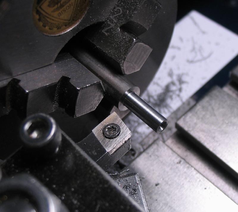
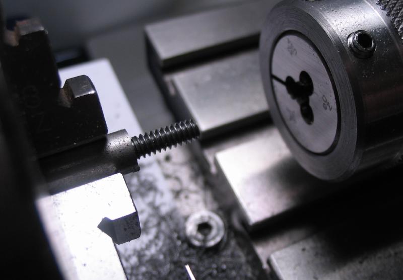
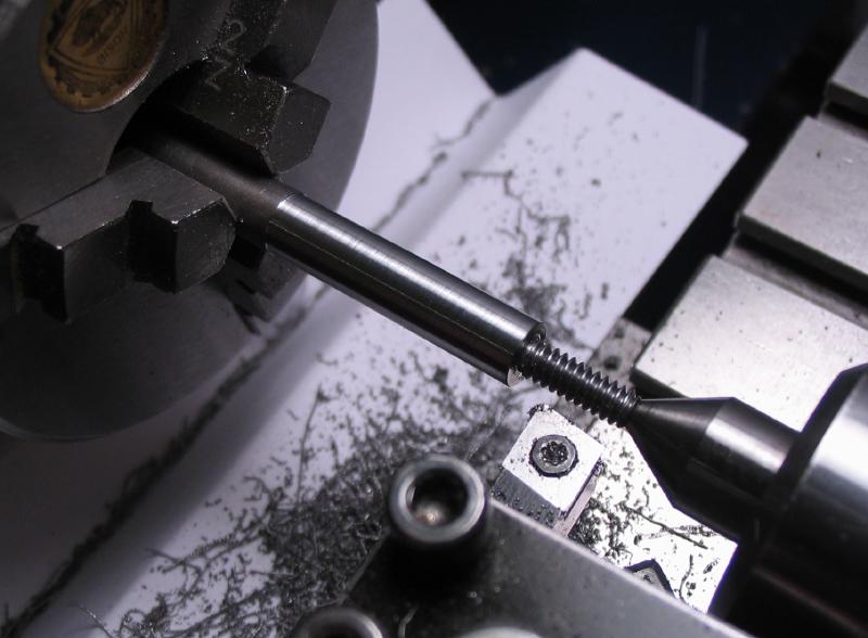
An arbor for the handle was made from 1/4" cold roll steel rod. It was turned and threaded #6-32 to fit the crank arm and then turned for a smooth fit the bore the handle. It was then reversed in the chuck to drill and tap for a stock #6-32 slotted screw, the head of which is slightly larger in diameter and will retain the handle. The handle was given a coat of mineral oil
|
|
|
|
|
|
|
|

|

|
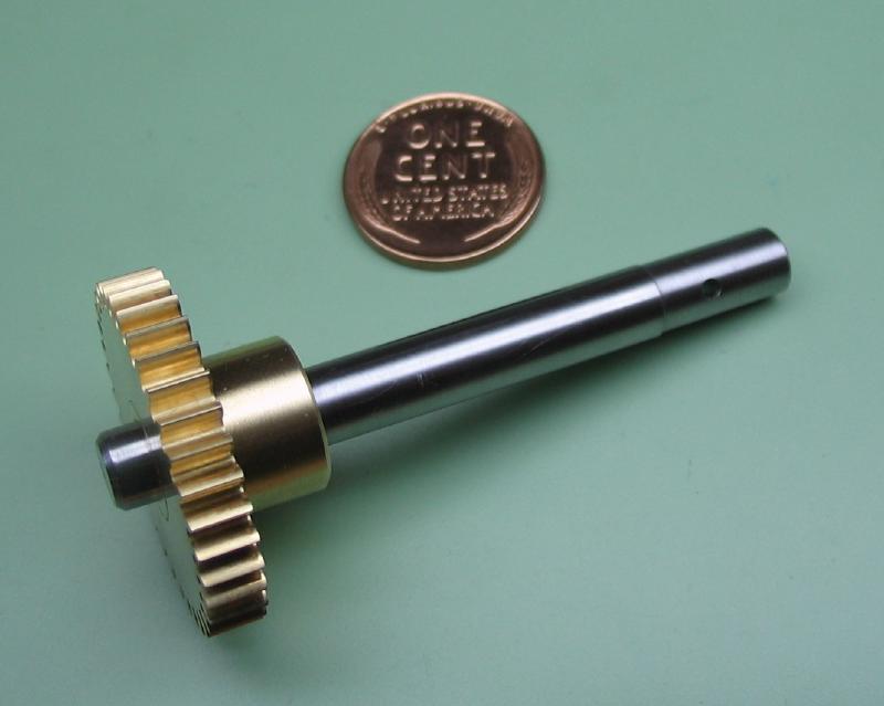
With the spindle complete, the collet was installed in the drive wheel, and the spindle hammered into the collet. The removable taper pin was shortened and ends rounded over, and the surface of crank arm were polished on emery paper. The primary driving components are complete.
|
|
|
The bracket is made from 1/8" x 1" brass bar. It is oversized since the hole for the spindle bearing will need to be bored to size and the extra length should help balance the load while mounted on the lathe faceplate. One side of the brass was worked over with a coarse file (No. 0) just enough to leave a reasonably flat face. The position for the spindle bearing was center drilled to aid in setting up on the lathe.
|
|

|
The tailstock center was used to position the bracket on the faceplate, and the work then clamped into place and drilled and bored to fit the bearing. The excess length was sawed off and the round edge brought closer to the desired shape using the filing machine attachment to the lathe.
|

|
|
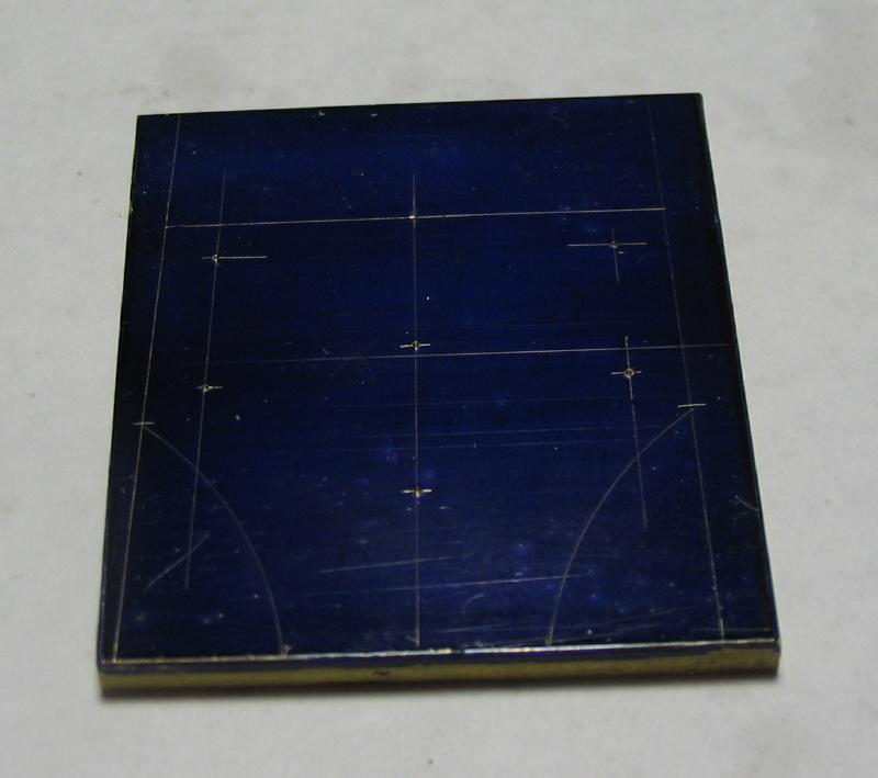
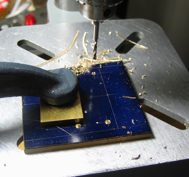
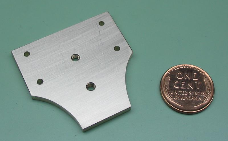
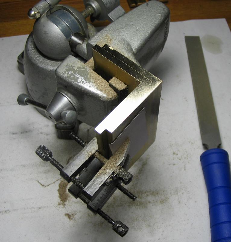
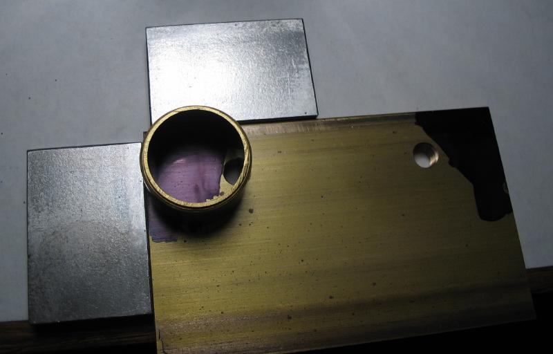
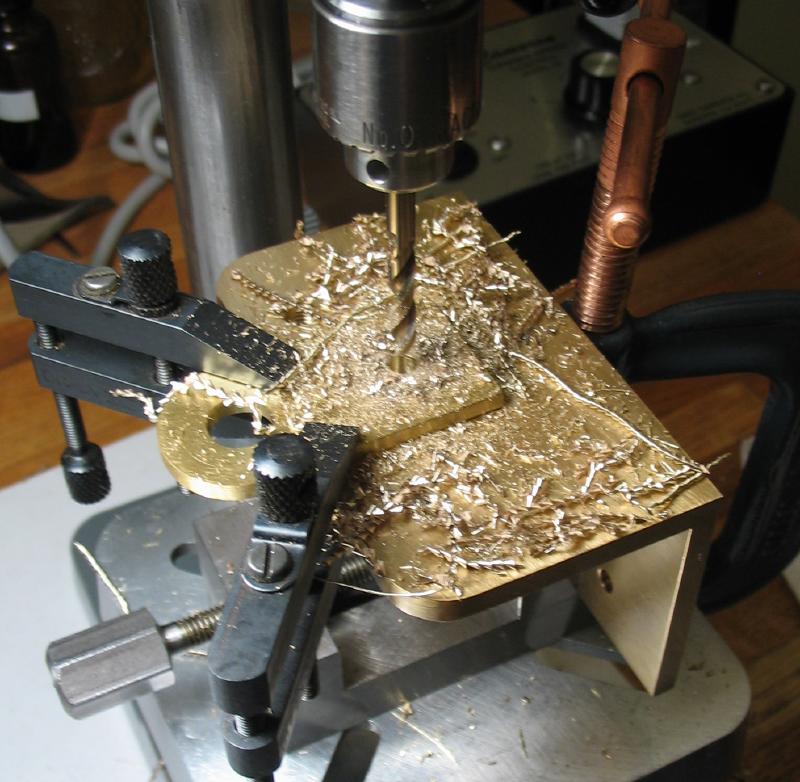
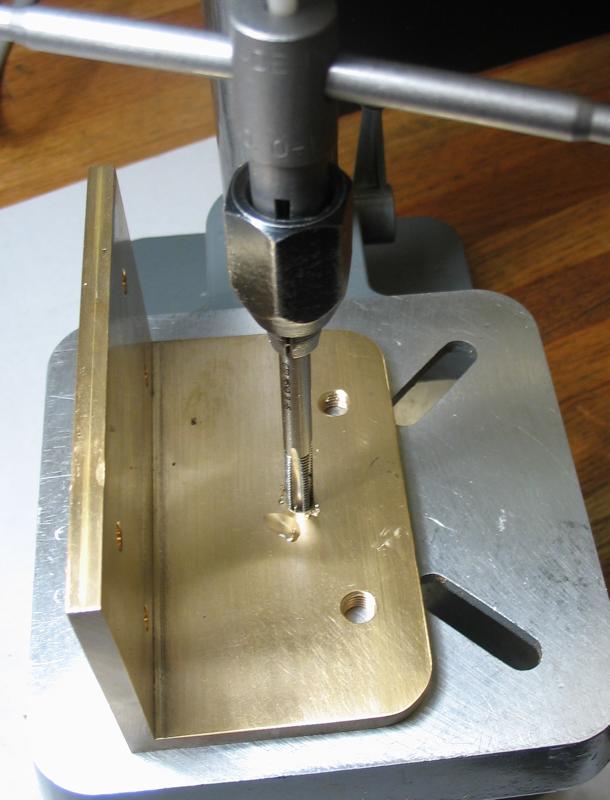
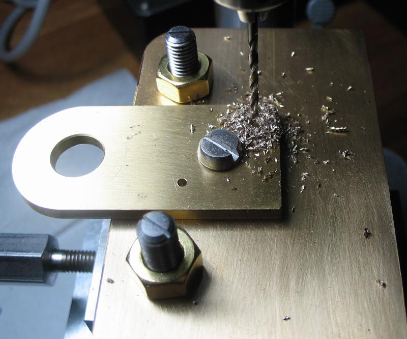
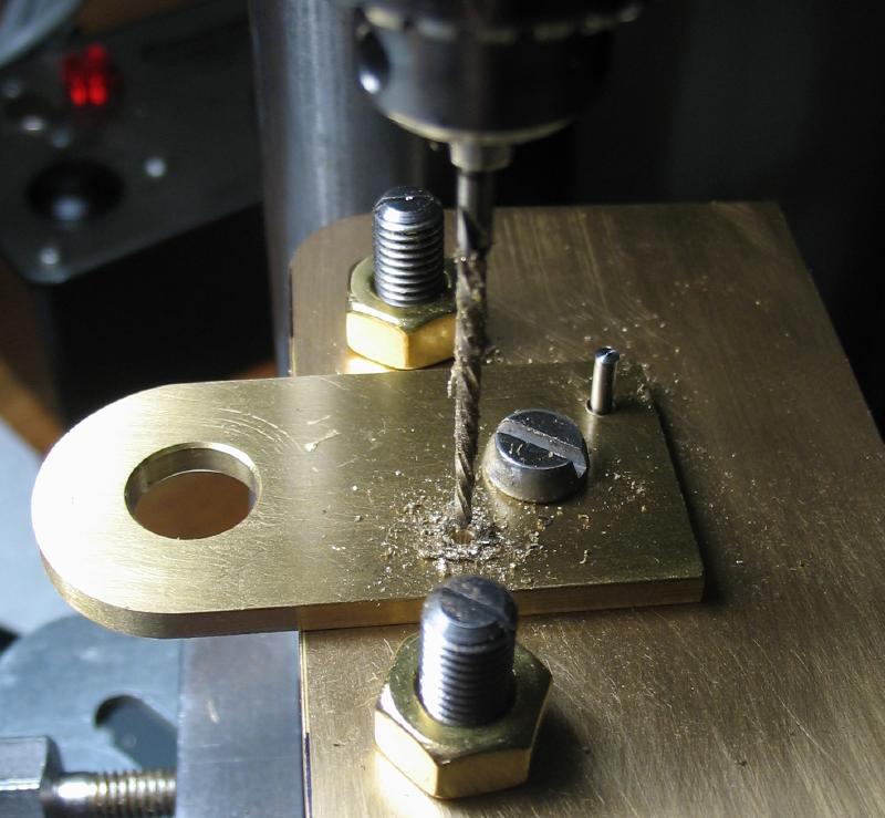
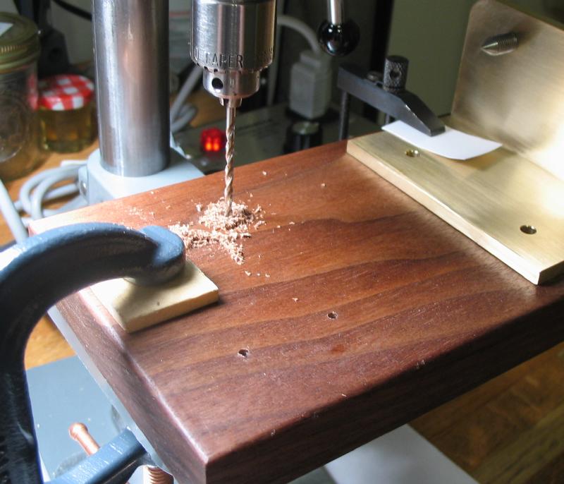
The trunnion plate is made from 1/8" brass, and this was an unevenly cut section of 2" x 1/8" bar that happened to be just about the correct size. The dimensions of the trunnion plate were scribed and center punched using one of the straight edges of the plate for reference. The four screw positions for the leadscrew nuts were drilled 2mm and the center two positions for attaching the tool holder were drilled No. 36 and tapped #6-32. These steps were carried out at the drill press. I use a small C-clamp with a small section of brass plate in between to protect the work from the clamp. The work was held free hand while tapping, but with a pin the drill chuck to help keep the tap upright.
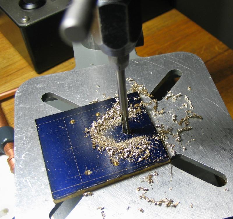
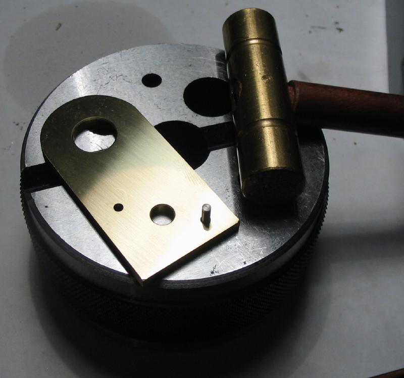
The desired shape was then sawed out with a jewelers saw and the edge evened out with half-round and flat hand files, and the faces were smoothed on 800 grit paper.
|
|
|
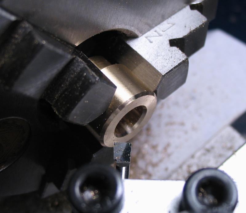
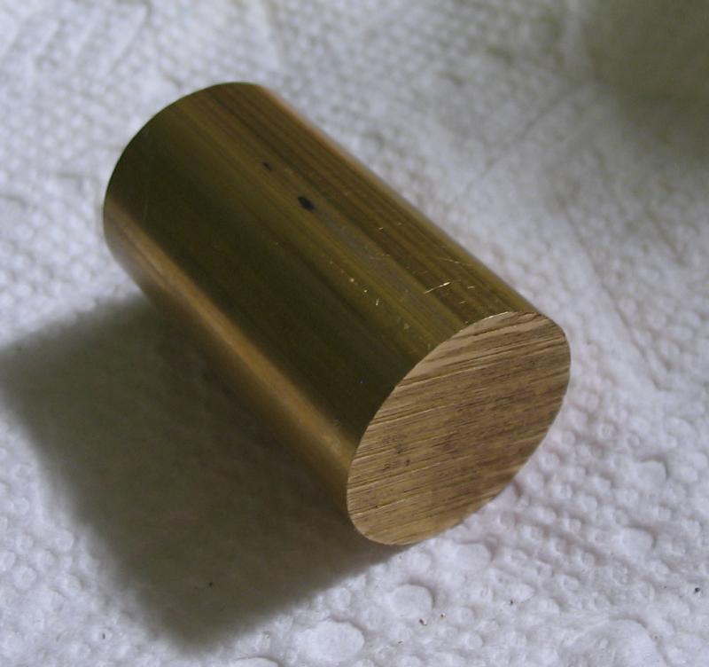
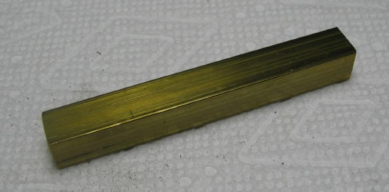
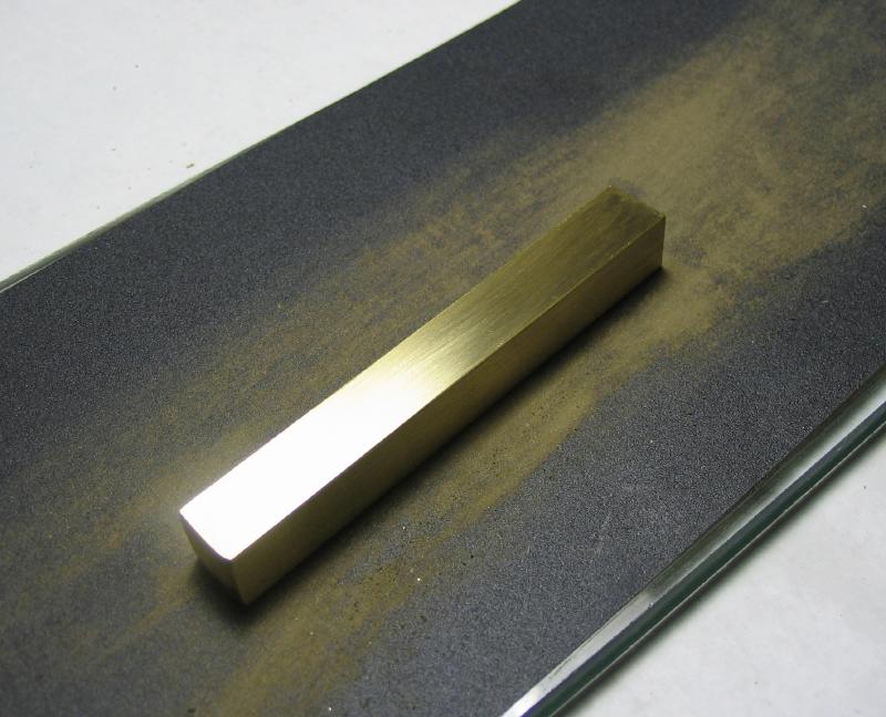
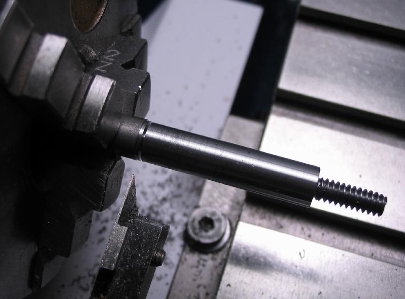
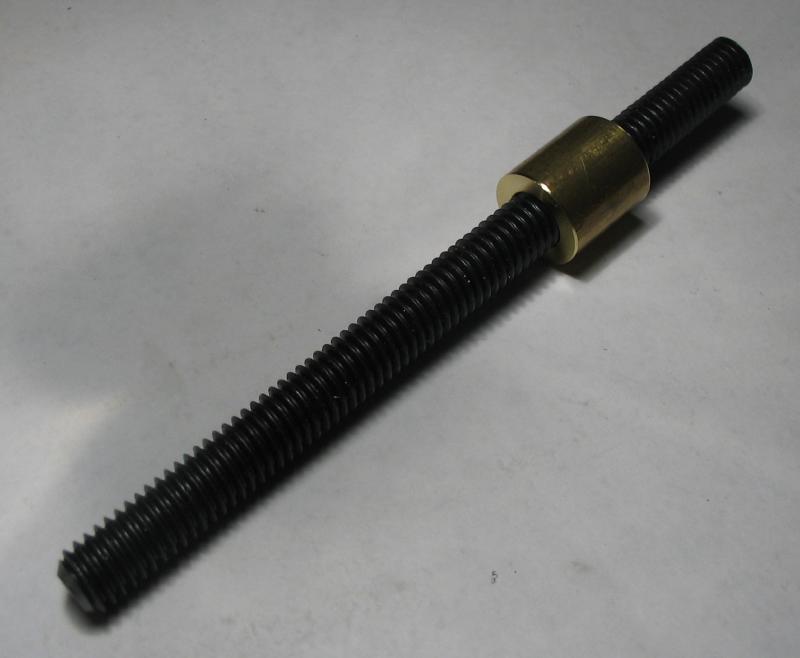
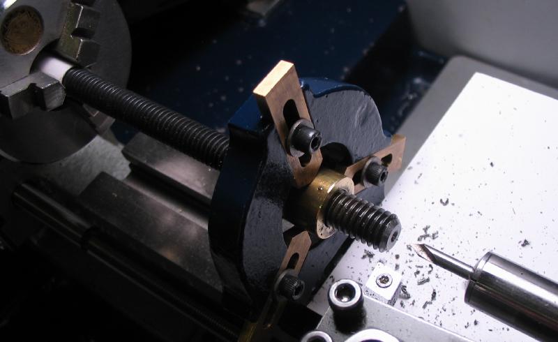
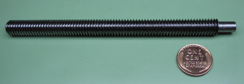
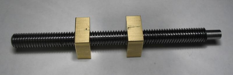
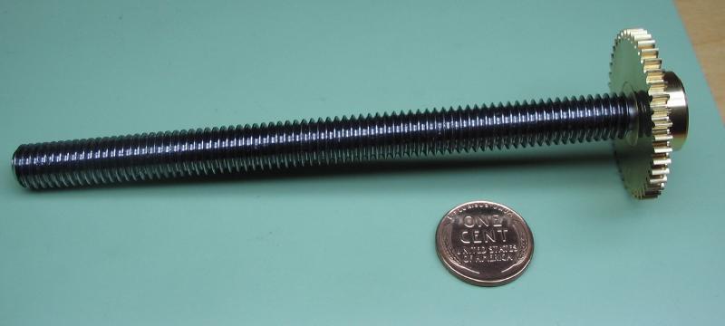
The leadscrew is the critical component of the tool, being that it provides the necessary thread pitch (in this case, a left-handed 16 turns per inch), and since lacking a screwcutting lathe, the availability of commercially made threaded rod was a deciding factor in trying to make this device. Although conceivably a threading die could be used to make the leadscrew, instead a roughly 5" length of pre-threaded rod was sawed off. It has a 3/8" diameter and In order to mount the rod on the lathe, a short piece of brass tubing with a slightly under 3/8" inside diameter was used to support the rod within the steady rest. A set screw helps to keep it in place.
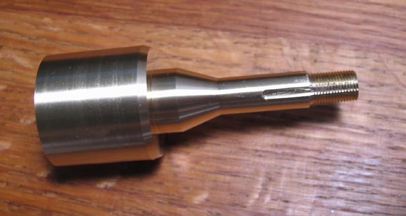
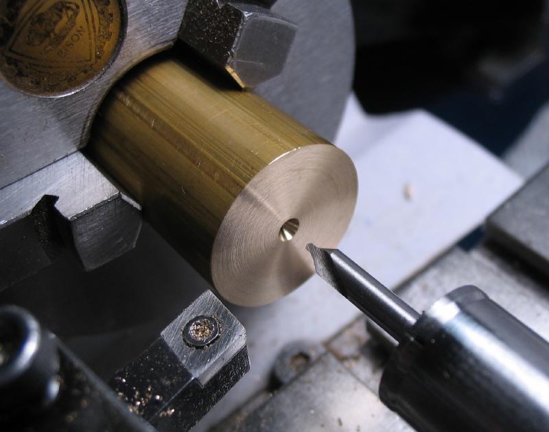
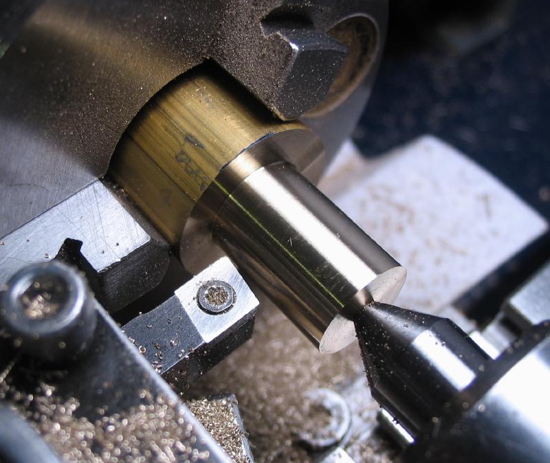
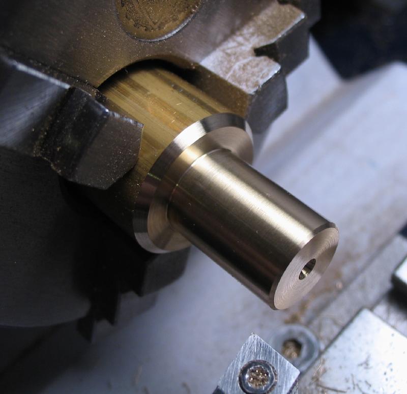
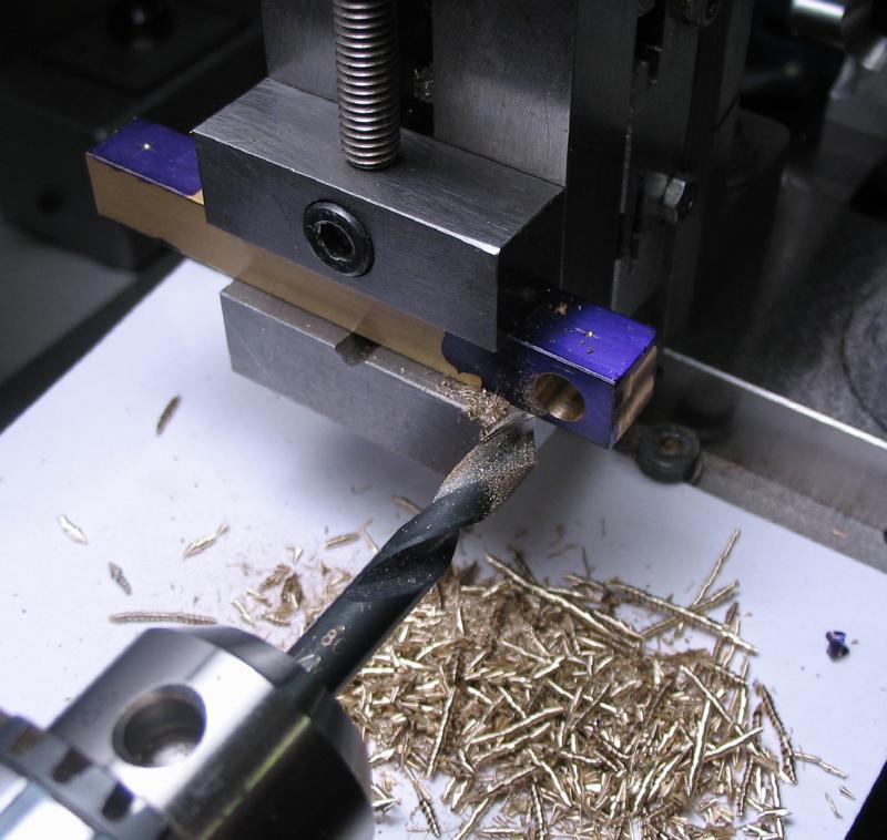
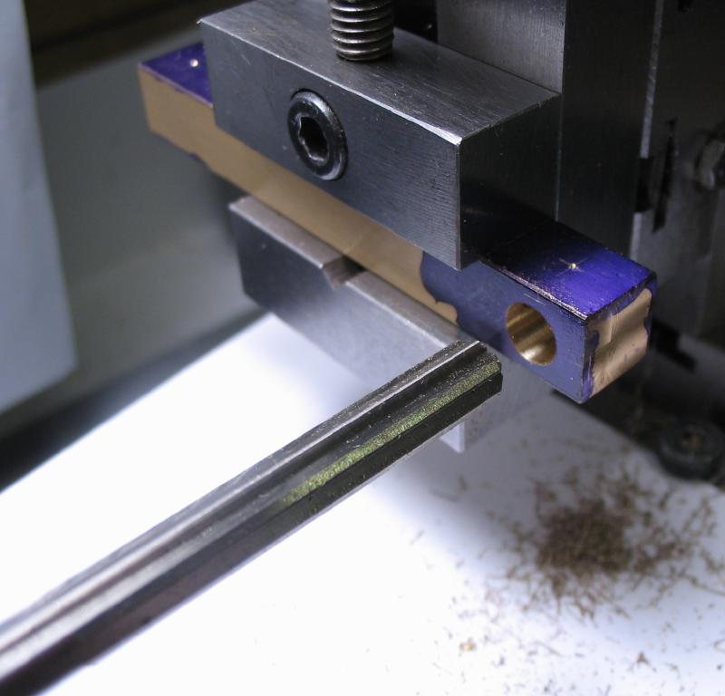
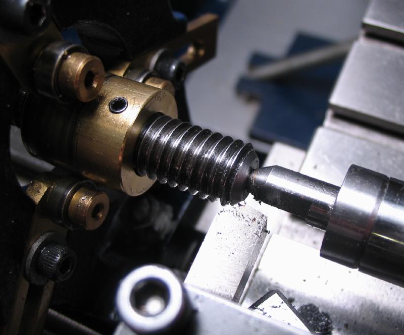
The ends were faced and center drilled so that the rod can be mounted between centers for turning the boss for the gear wheel, and the leadscrew will run between centers in the finished tool. A slip of paper card was used to protect the thread from the dog's fixing screw. A boss was turned to about 6mm and to fit the collet of the matching gear wheel.
|
|
|
|
|
|
|
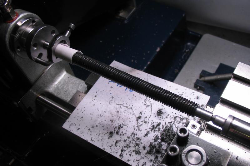
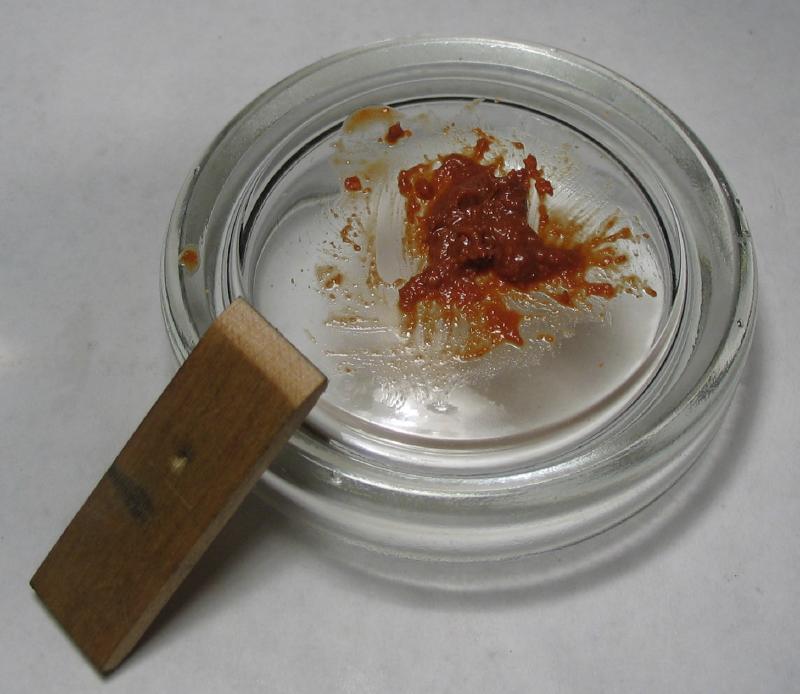
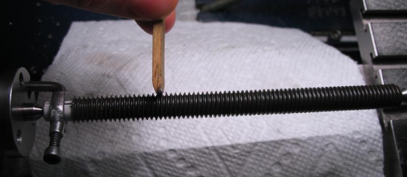
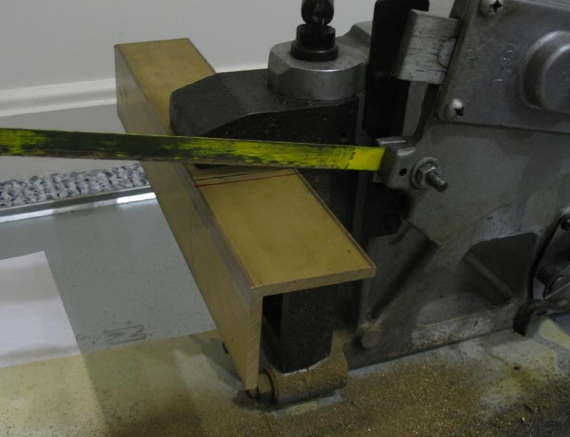
The threaded rod stock has a black oxide finish of some sort, which is likely useful for usual applications, but as a leadscrew, it will be important that the action is very smooth. So, the threads were polished with "tripoli" (Vigor brand), the paste was mixed with a few drops of oil and applied with a piece of soft wood that was sharpened to a coarse edge with a file. The wood takes the shape of the work after a couple passes; paste was applied and the edge of the wood pressed into contact while the lathe is running, and the thread will drive the polisher towards the tailstock. After quite of few passes with the polisher and several refreshes of paste, there was still a small amount of oxide remaining, however, the surface smoothness is much improved.
|
|
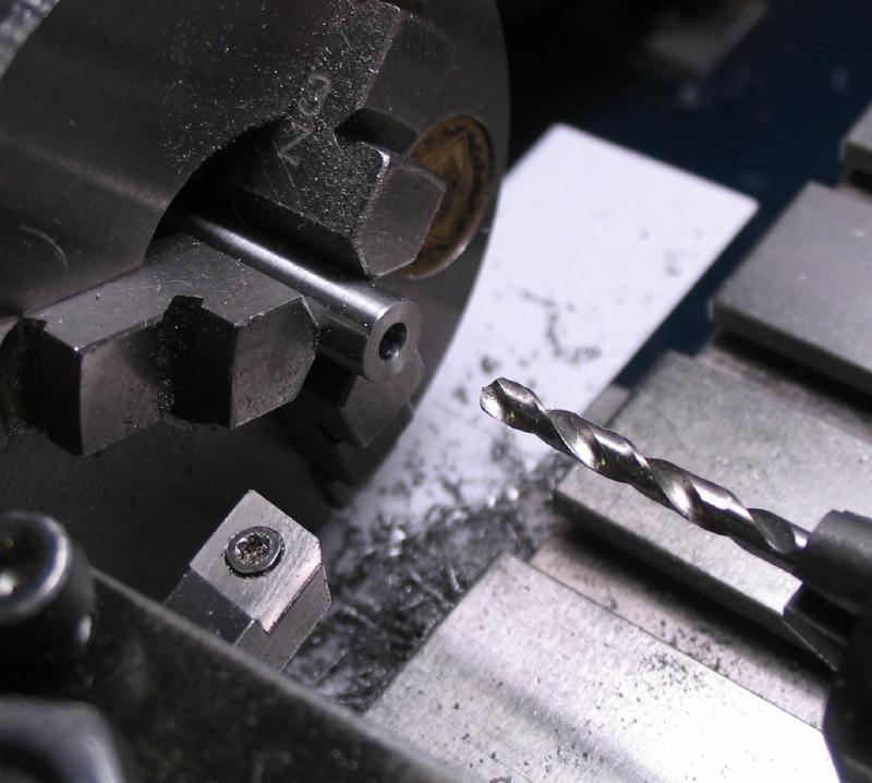
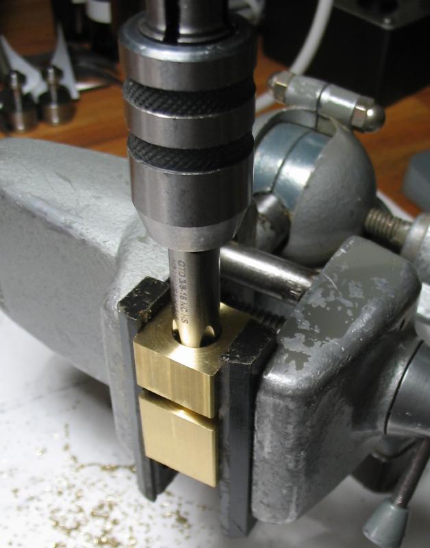
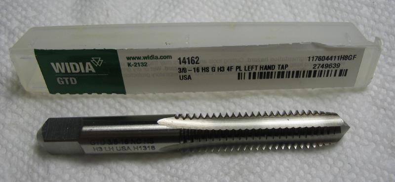
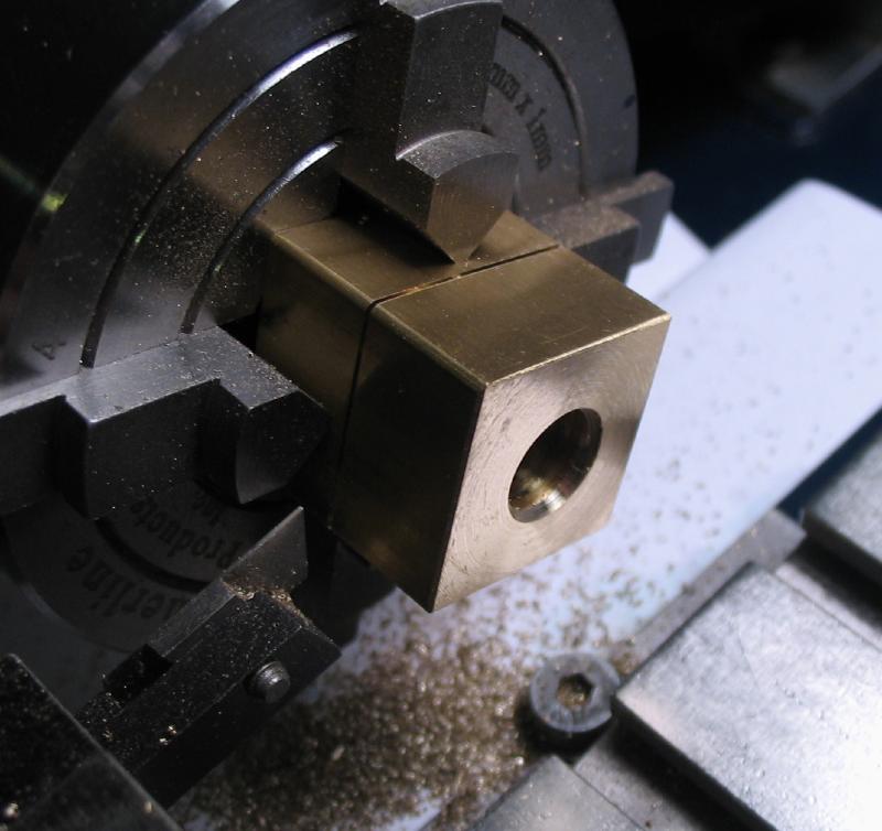
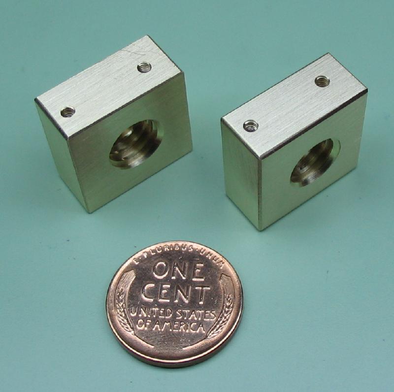
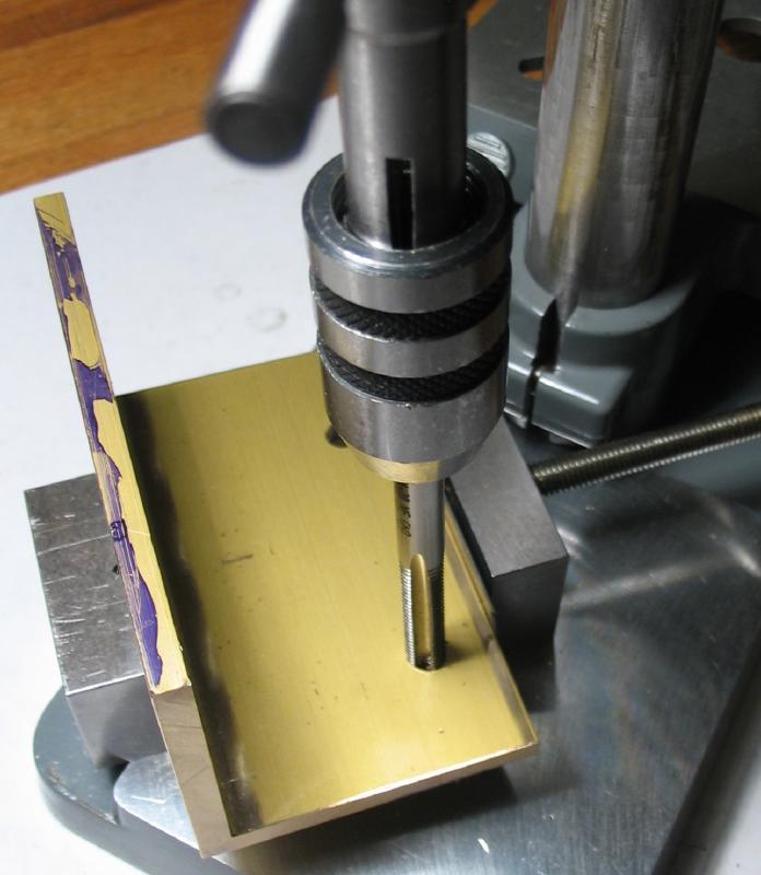
Mr. Wilding describes using coach bolt nuts for the leadscrew nuts, however nuts in the thread size needed were not found, but a tap was, so the nuts were made from a roughly 3/4" length of 3/4" square brass bar. The face that will attach to the trunnion plate was milled flat and both nuts are started as one piece so the distance between the center of the bore/thread and top face are the same after separating. The bar was mounted in the 4-jaw chuck and faced, drilled, and bored to almost 8mm.
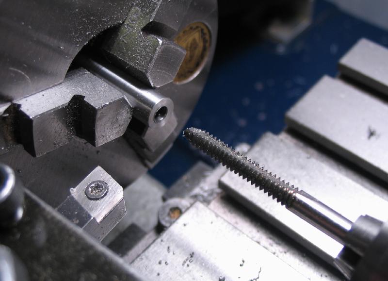
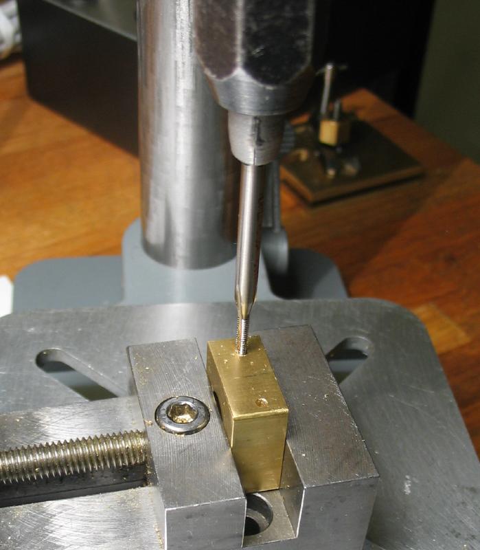
To accommodate the large tap and tap-holder, the tapping process was carried out in the vice using a tap guide made from another 1/2" length of the same square brass stock and bored to clear the tap with a close fit. Both were mounted in the vise and the guide keeps the tap upright.

|
|
|
|
|
|
|

|
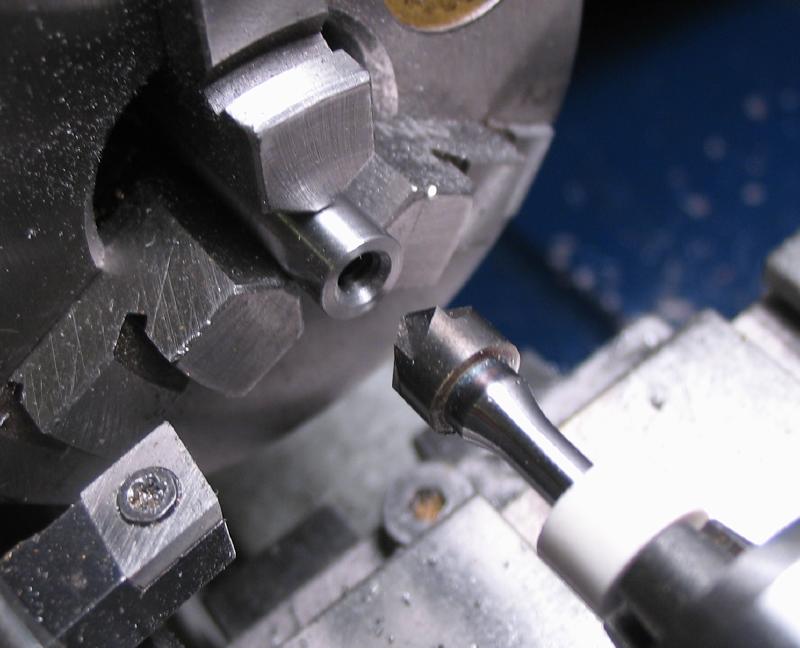
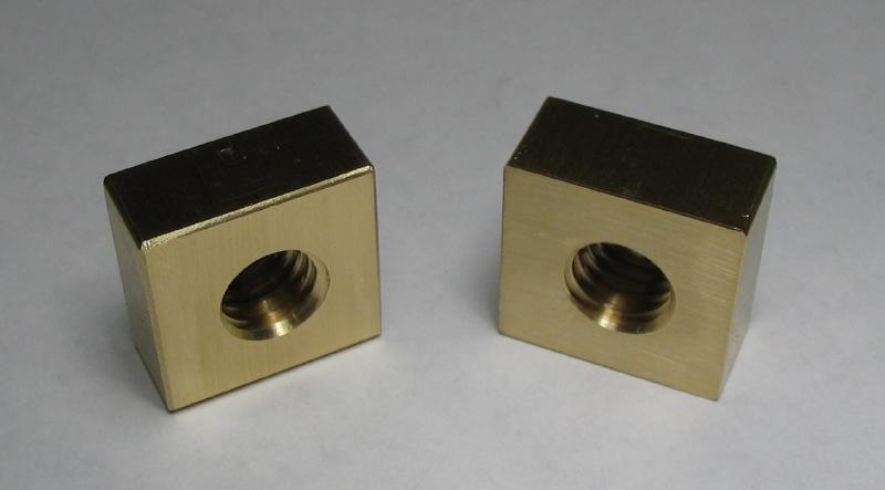
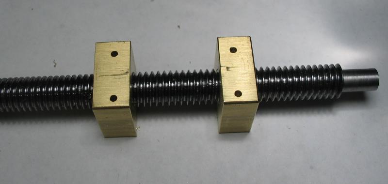
The nuts were parted and the inside faces turned flat. The threaded bore was countersunk with a boring bar to remove the sharp edges. They were then tried on the leadscrew with the machined face aligned to their original orientation before parting, and spaced on the leadscrew to match the width of trunnion plate as best as possible for now.
|

|
|
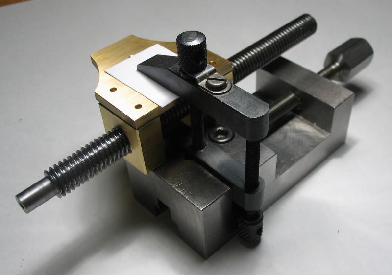
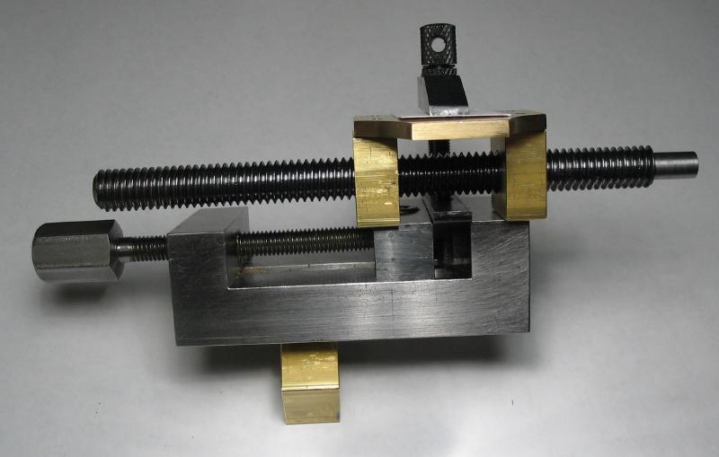
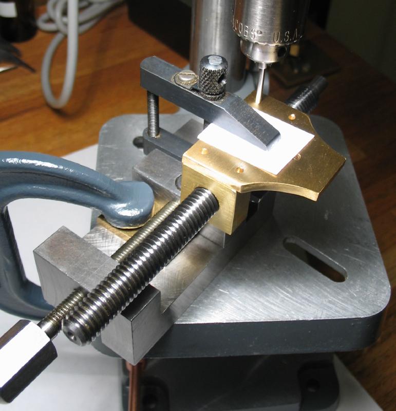
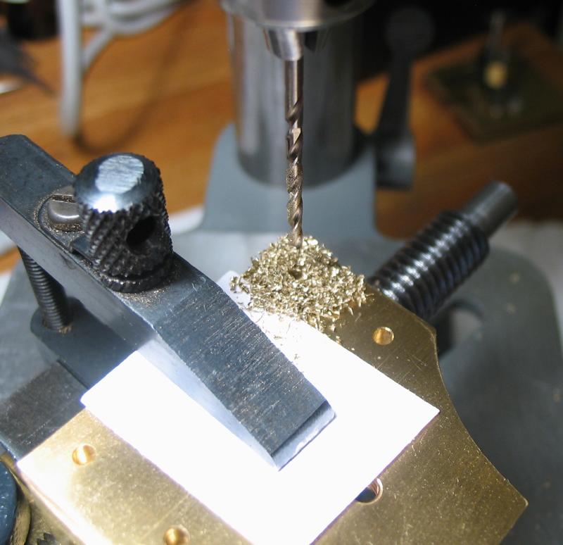
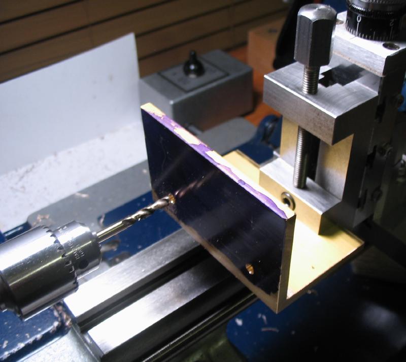
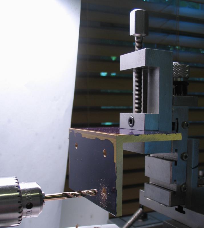
A toolmaker clamp was mounted in the machine vise and with the leadscrew nuts sitting on top of the vise, the trunnion plate was clamped into place. A length of 2mm drill rod was used to center the assembly on one of the four screw positions and the work clamped to the drill press table. The nuts were then drilled 1.6mm each position to be tapped afterward M2x0.4.
|
|
|
|
|
|
|
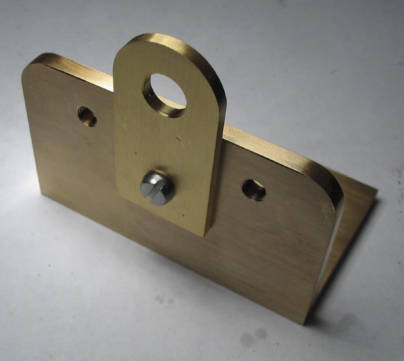
The assembled wheel and collet were then installed, although it was not a very tight fit, so a dab of Loctite will be needed when permanently installed.
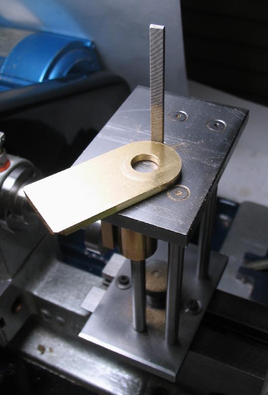
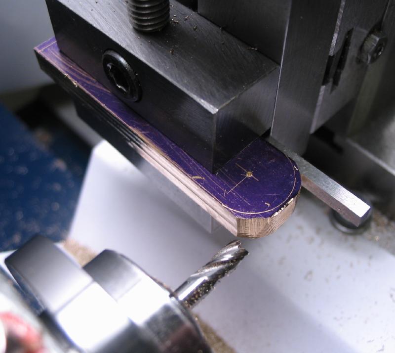
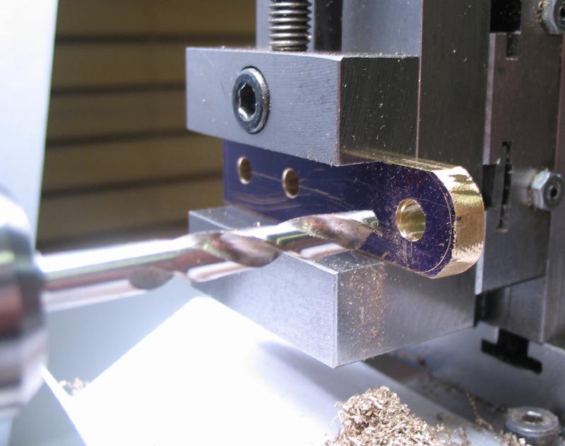
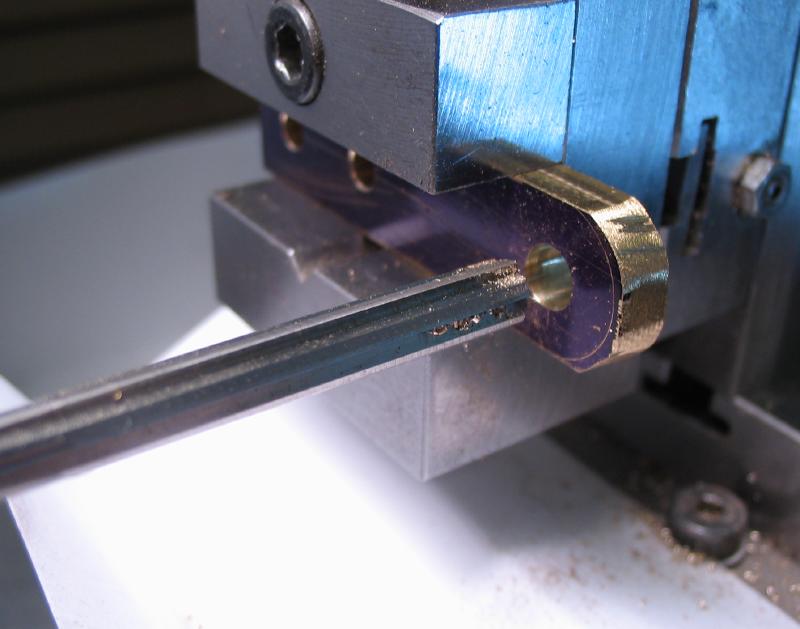
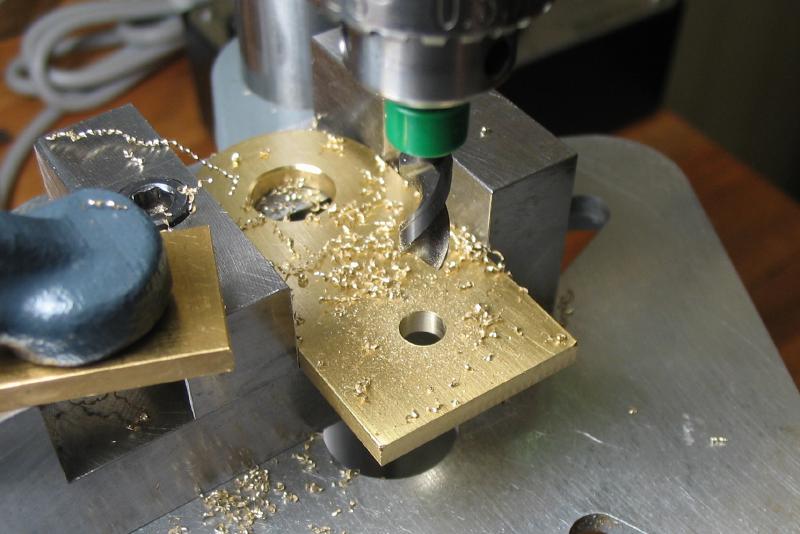
The tool bit holder is made from 3/16" brass plate. The dimensions were laid out and center punched. It was sawed out and the sides milled parallel. It could held more securely in the vise for then drilling the two screw positions and drilling and reaming the 5mm tool holding position. The end was drilled and tapped M3x0.5 for a set screw. Finally, the end was filed to a more rounded shape than was left by the saw.

|
|
|
|
|
|
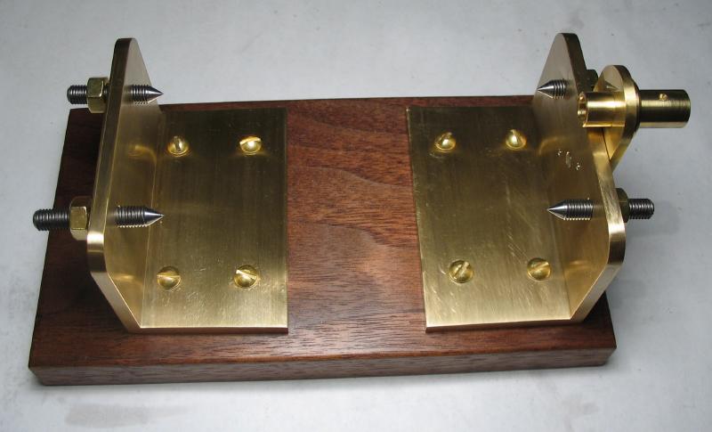
The two frame pieces were made from brass angle bar that is 3/16" thick and both legs 2" wide. Lengths of about 3.25" were sawed off and the two pieces stacked together in the vise to file the ends even. A pair of clamps were added to keep the two pieces together when flipping over.
|
|
Positions for four screws in each end of the frame were laid out as well as the positions for the two center screws. The size of drills required this to be setup on the lathe, which involved some awkward arrangements, but the eight clearance holes (4.2mm) and four #3 holes were drilled without incident. The latter four holes were tapped 1/4"-28 using the drill press for getting the tap started straight.
|
|
|
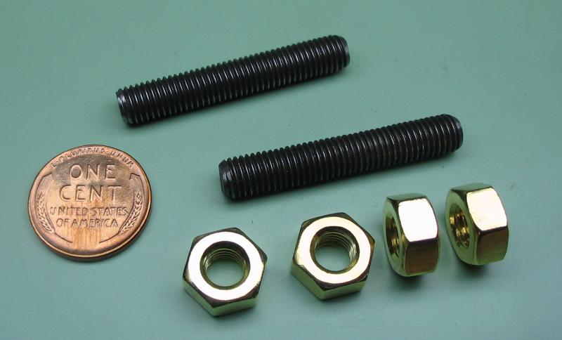
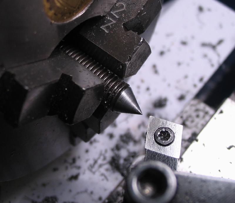
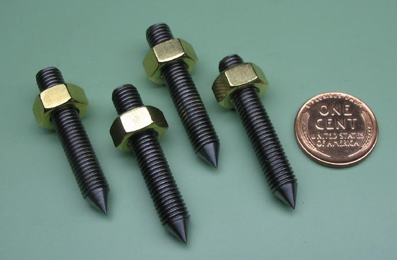
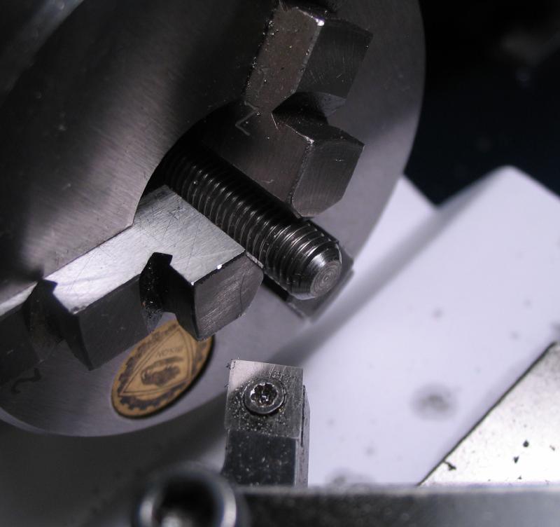
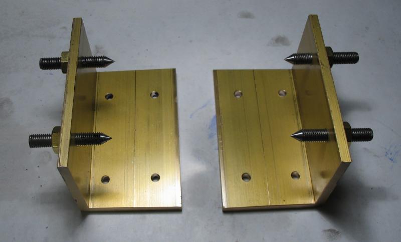
The centers are made from some lengths of "studding"; 1.5" long threaded rods (1/4" - 28) with stock brass nuts with matching thread. These are likely much longer than needed, but can be shortened later after test fitting. Each was turned with a 60 degree point that was then polished with India and Arkansas stones. After a test setup, the centers could be shortened as desired and need to at least clear the crank arm. The cut ends were then slotted with a 0.025" saw so they can be tightened with a driver.
|
|
|
|
|

|
The top corners of the frame pieces were rounded over. A round piece of stock was used to scribe guide marks that was then following with a jewelers saw and cleaned up with files. The surfaces were then worked over with emery paper.
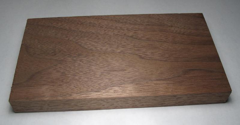
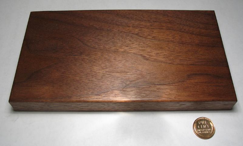
A roughly 7" length of 3/4" x 4" walnut was selected to form the base of the tool. The corners were given a 1/8" radius using a Veritas cornering tool and the surfaces given a light sanding before applying a coat of oil.
|
|
|
The tool was assembled on the base and the frame ends clamped in place after squaring the frames piece with the base, using a square against the inside edges. The leadscrew and winding barrel with gear attached were put between their centers to help with finding the needed alignment of the frame pieces. The spindle bracket was clamped to frame and the drive wheel installed. The position of the bracket was moved about until a good depth was found with both gear wheels. The work was disassembled, except the bracket and frame piece, which were taken to the drill press to drill through 4.2mm for tapping the frame piece M5x0.8. The bracket hole was enlarged to 5mm to pass the threads of a stainless steel cheesehead screw that happen to be on hand, although it needed to be shorten to about 8mm in thread length.
|
|
|
|
|

|
The tool was reassembled as before, but the bracket attached with the screw and the depthing checked. There was enough shake in the hole to find a smooth running position, but the hole can be enlarged if needed. The screw was tightened to preserve the desired arrangement while fitting steady pins. Two diametrically placed steady pins were installed by drilling through the bracket and frame and reaming with a 6/0 pin reamer. They were separated and a pin driven into the bracket. The frame hole then needs a slight enlargement with the reamer to fit the pin. The second pin was then fit likewise. The excess length on both sides was then sawed off and the inner end rounded over with a cup bur and the outer end filed flush with the bracket surface and rubbed on emery paper. The spindle bearing was not a drive fit, but with the bracket now finished, the bearing was installed with Loctite.
|
|
|
|
|

|
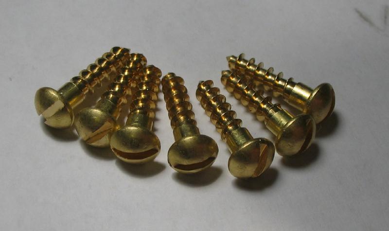
The frame pieces were then permanently attached to the base with #8 brass wood screws that are about 11/16" in length. With the tool assembled and frames clamped in place, a fine point Sharpie pen was used to mark the positions for the screws on the wood base. The positions were drilled 3/32", using the drill press depth stop to keep from drilling through (and into the drill press table). A large screw driver was used to install the screws.
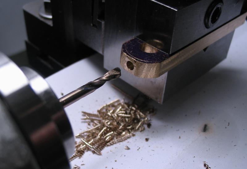
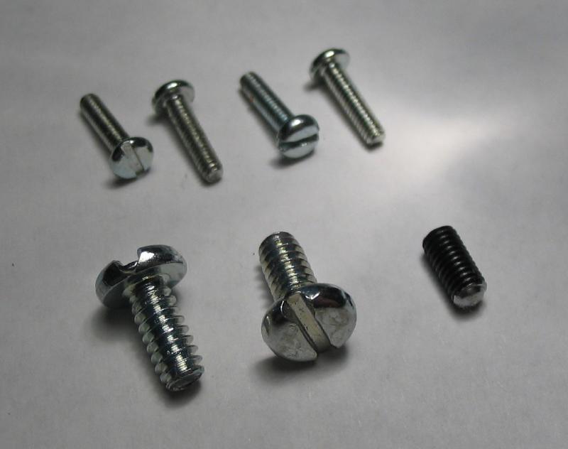
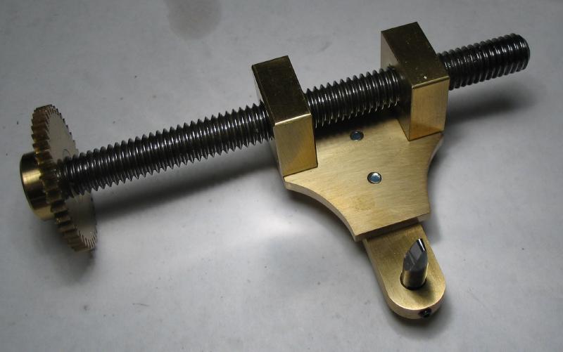
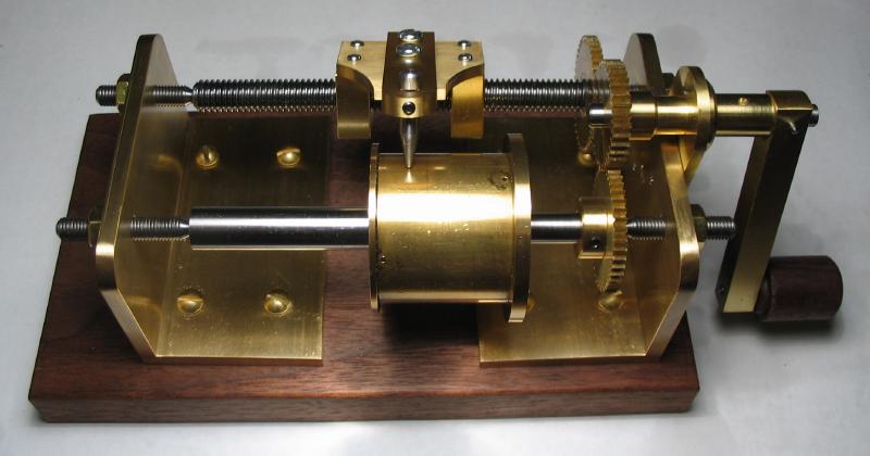
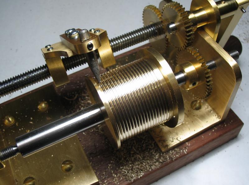
The trunnion and cutter holder was assembled and installed on the lead screw. The hardware includes slotted zinc plated steel screws (#6-32 x 5/16" and M2x0.4 x 8mm) and a M3x0.5 set screw that was shortened slightly and rounded over with a cup bur. A cutter bit was started that that can be seen in the photo and has a rounded tip and turned with a 20 degree taper, but a different will be taken. However, it was useful for testing the setup at this point.
|
|
|
|
|
|
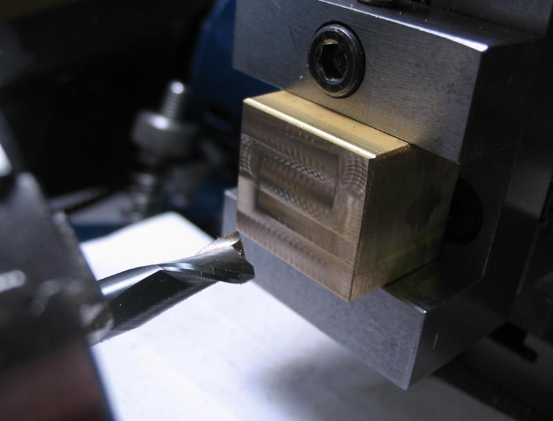
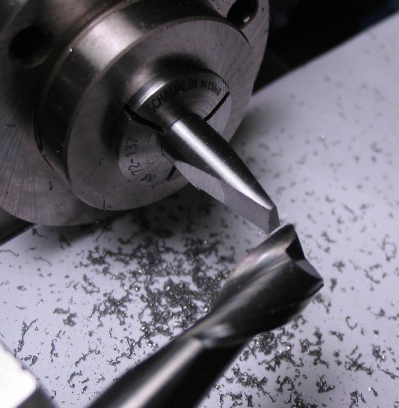
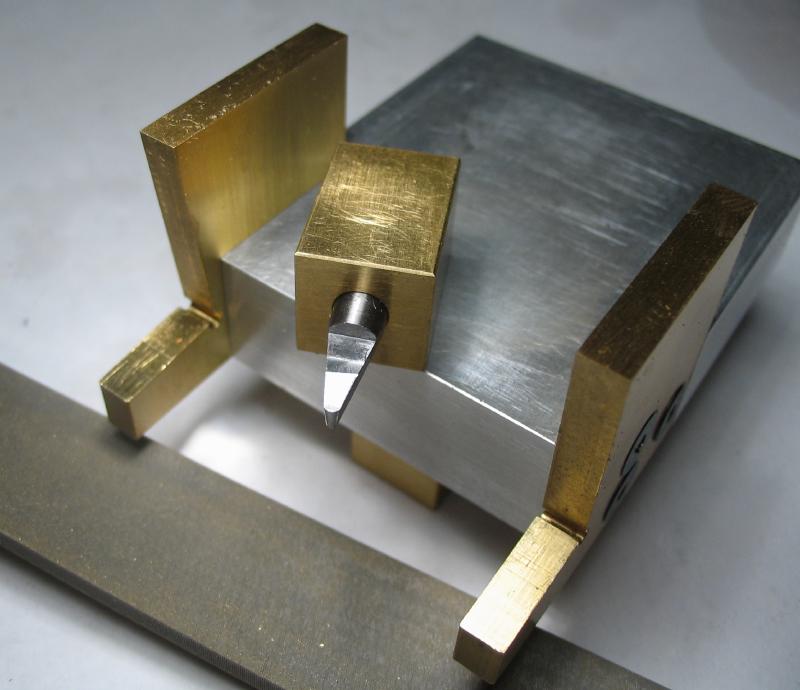
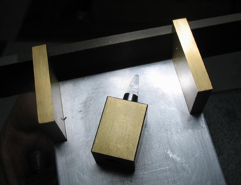
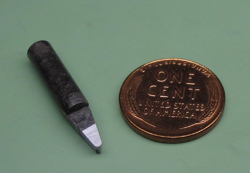
The cutter was made from 5mm oil hardening drill rod. Most of the dimensions mirror those described by Wilding for the fusee groove cutter. A length of rod just under an inch long was faced and chamfered to true up the ends and a 1/4" wide and 1mm deep flat milled. A brass block made for holding such a cutter blank (described on the honing jig page) was used to mill the top face, which is on the other side.
|
|
|
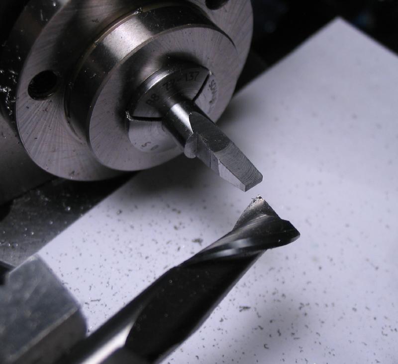
The cutter was moved to the dividing head, which was setup on the cross slide offset at an angle of 10 degrees, and the dividing head used to rotate the cutter 5 degrees. This was used to mill the side of the cutter tip and the process repeated for the other side (upside down). Using the same 10 degree offset, a negative rake was milled into the top face. The dividing head was re-positioned to mill a 7 degree clearance angle on the tip.
|
|
|
|
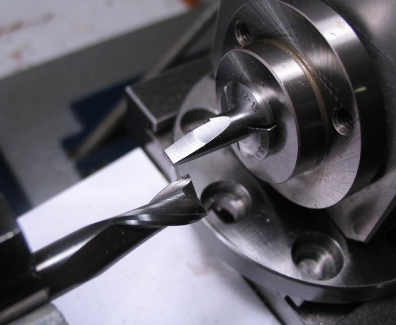
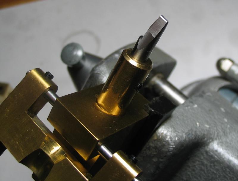
The cutter was replaced in the brass block and the honing jig was used with a hand file (in place of a stone) to give a rounded shape to the tip. The rounded shape is done by hand, but the jig helps keep the angle uniform. The edge was then smoothed with an India oilstone, and the cutter then moved to the lapping tool to smooth and sharpen the top face and sides.
|
|
|

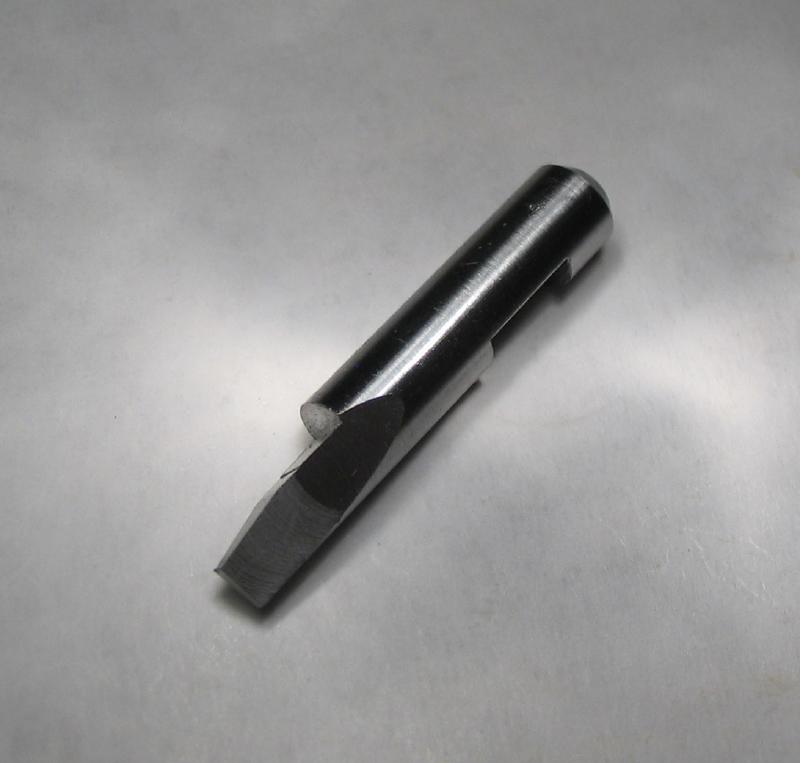
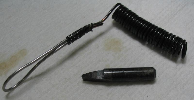
A holder was fashioned from stainless steel wire and the cutter hardened by heating to bright red and quenching in oil. The tip and three faces of the tip were resharpened.
|
|
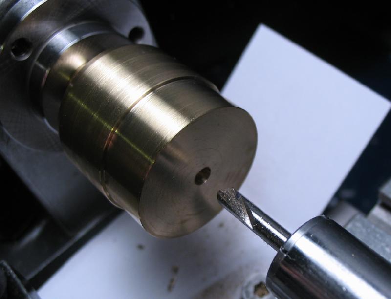
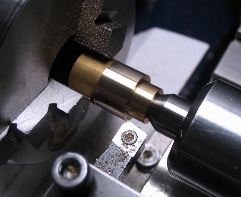
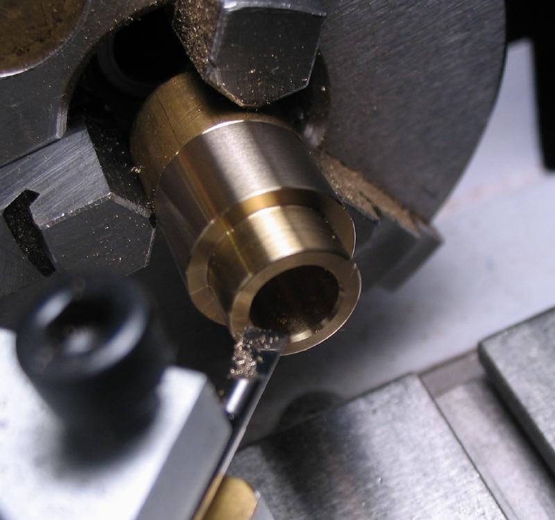
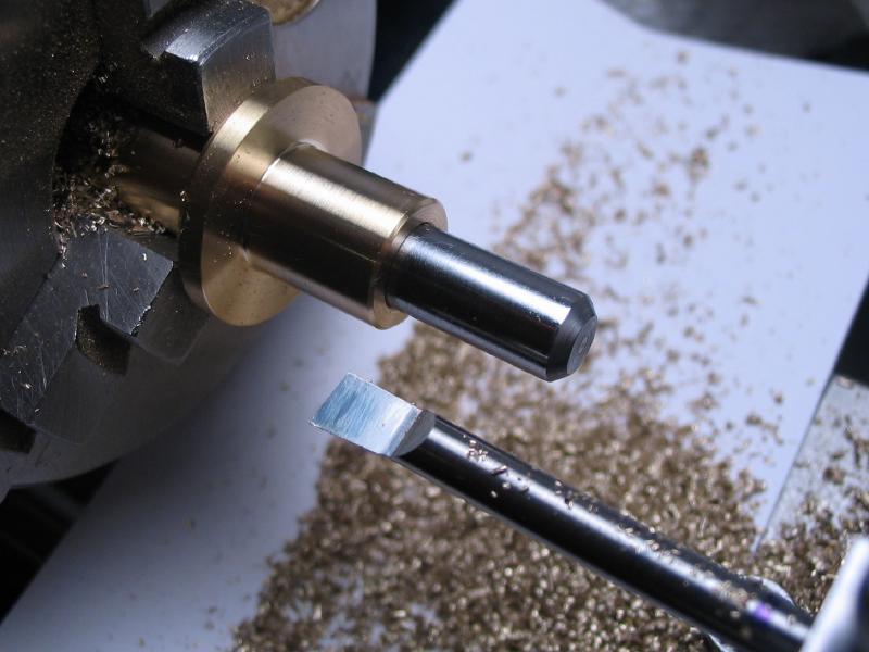
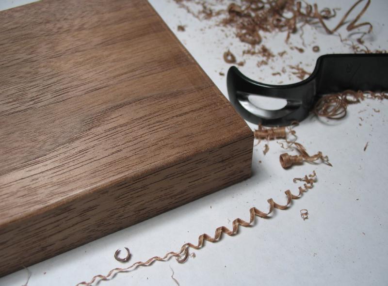
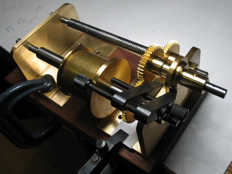
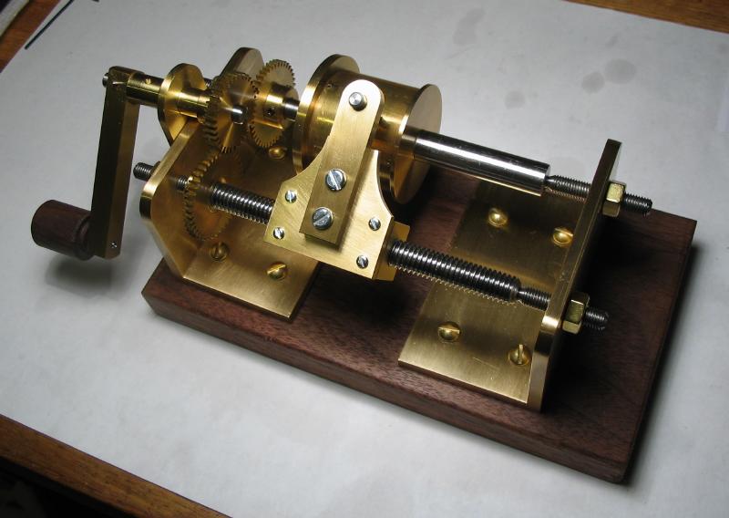
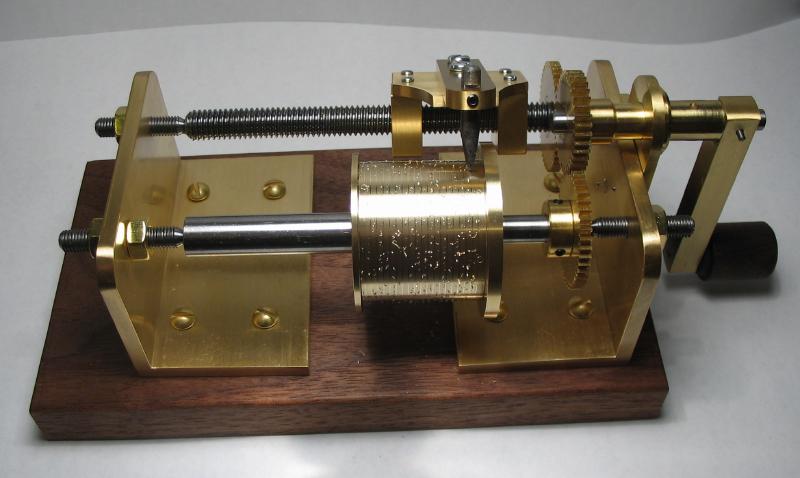
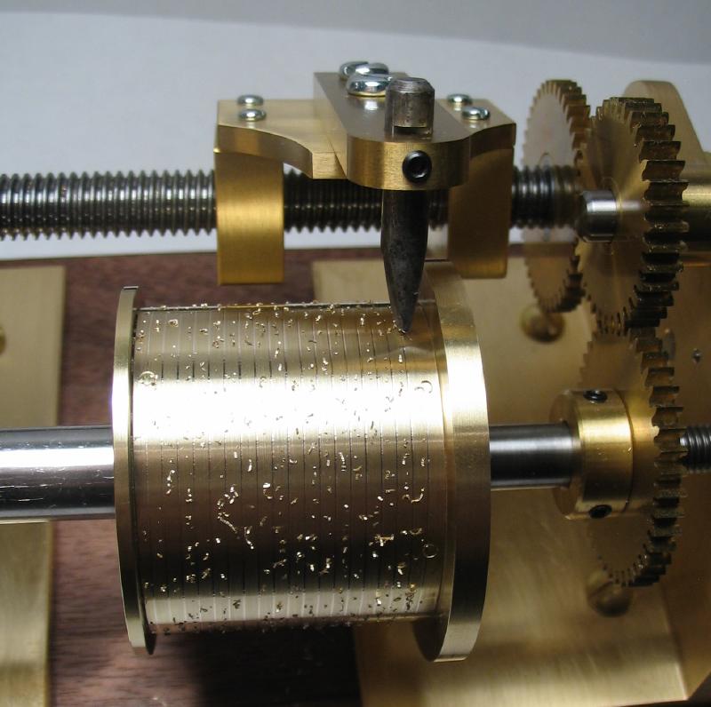
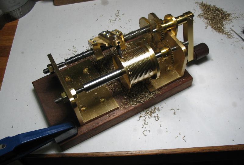
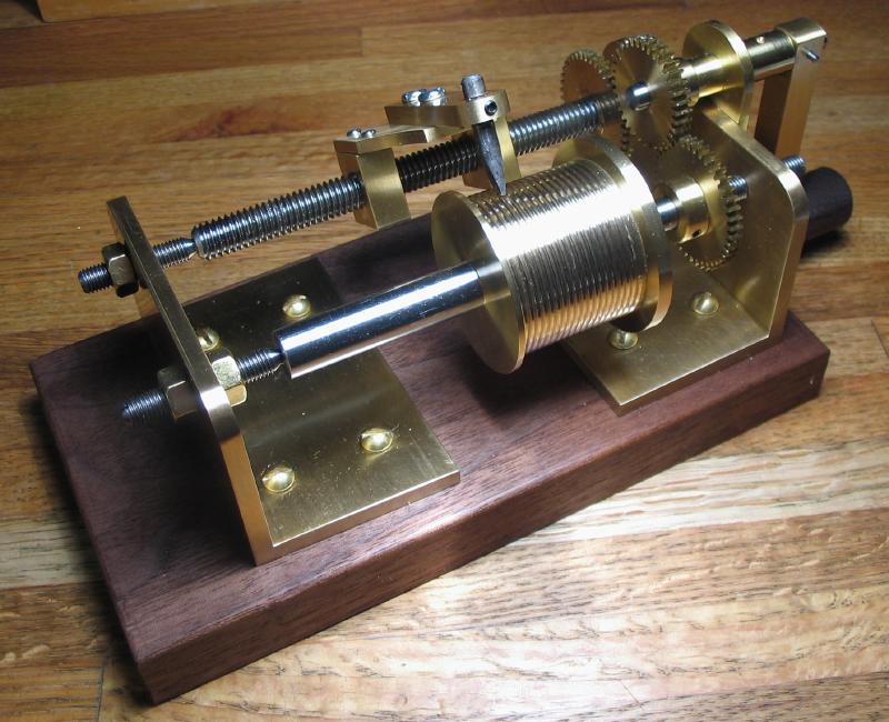
With the cutter sharpened, the device is ready to carry out its intended function. The winding barrel was turned between centers on the lathe to provide a true diameter. This is described on the barrel-making page, but its finish is improved compared to photos above. The grooving device was assembled and the centers well oiled and tightened, the locking nuts were tightened up as well and an extra nut was added to one of the centers that was fairly long. A clockwise advance of the crank rotates the barrel counterclockwise and feeds the cutter from left to right; hand pressure is applied to the cutter to provide cutting action. Chatter was the primary issue, and seemed to be a result of the hand-powered nature. Once the right feed and speed is found, ribbons of brass were made. Dig-in and chatter marks were smoothed with a round needle file as needed between passes of the cutter. A sufficiently deep groove required quite a few passes of the cutter, but having spent a fair deal of time making the device it was enjoyable spending time using it.
After the first pass of the cutter
|
|
Mr. Wilding suggests adding a strip of wood underneath to allow the tool to be mounted in a vise. Not having a large enough vise, the surplus length of the wood base was used to clamp the tool to the bench top.
|
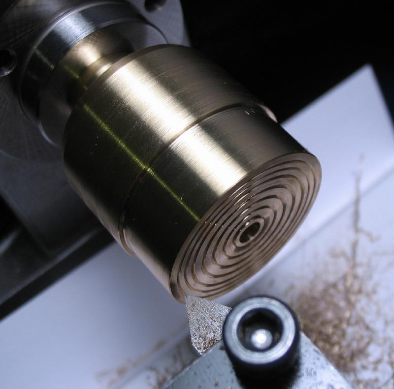
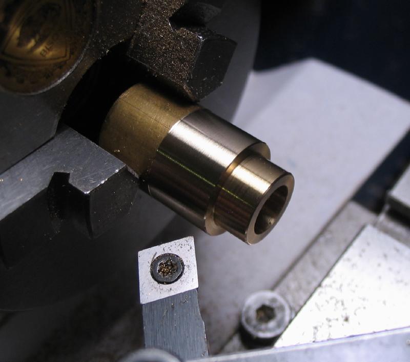
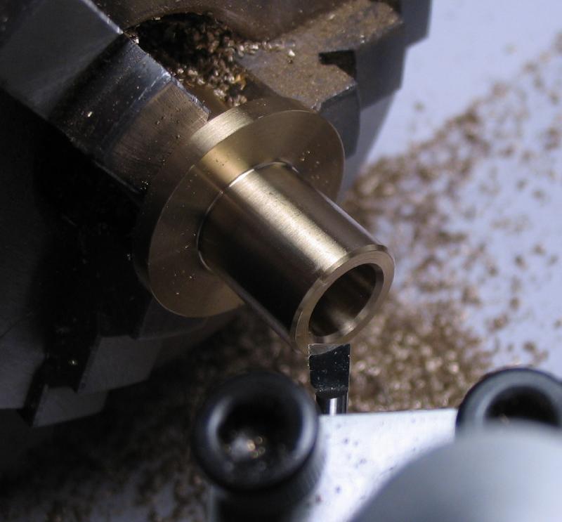
Close to full depth
|
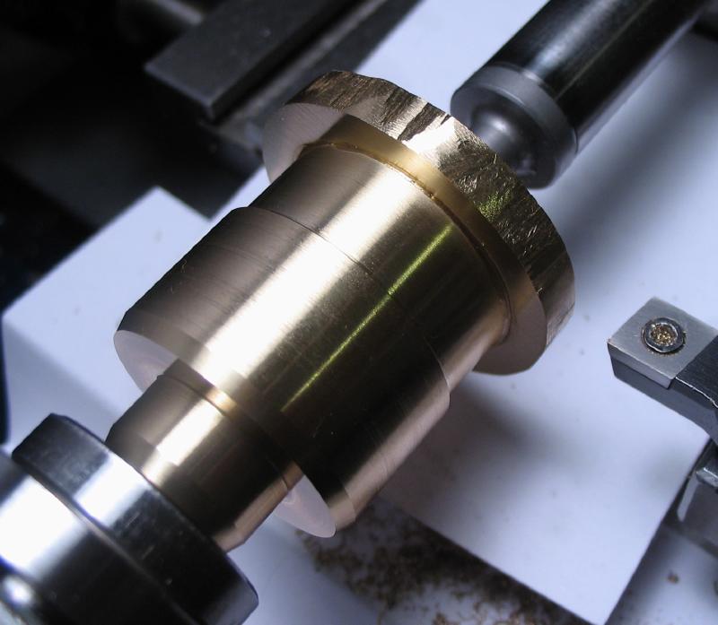
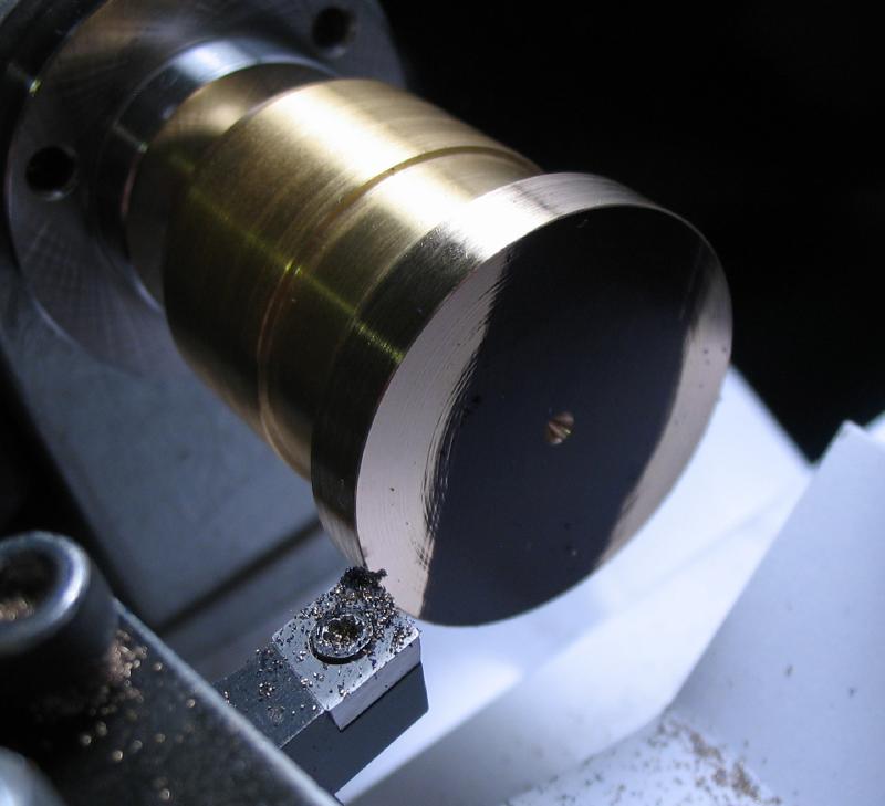
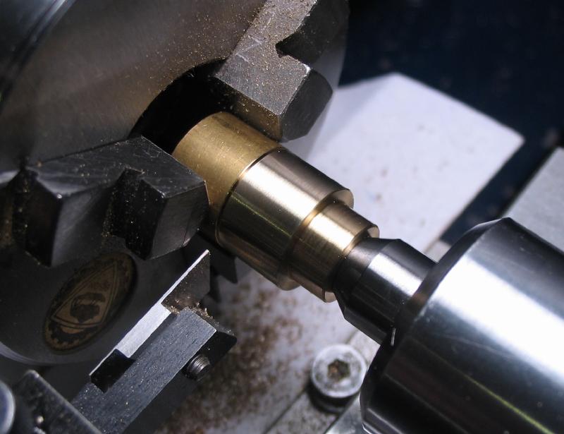
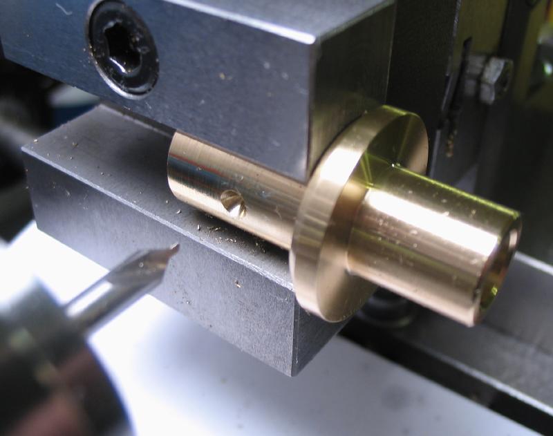
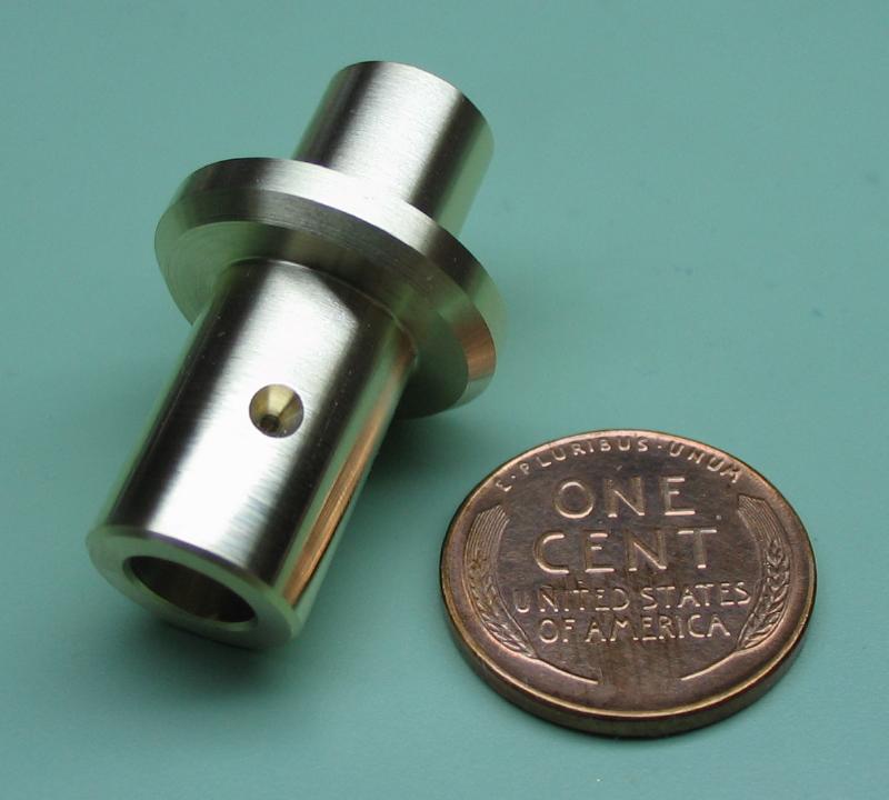
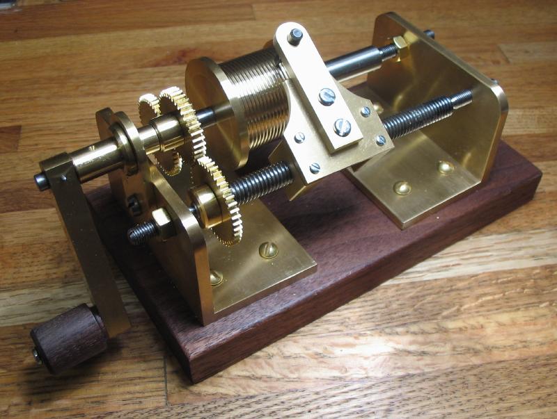
A couple final photos after tidying up.
|
|
