The Escapement
This watch will use a Thomas Earnshaw style spring detent chronometer escapement. Of the conventional escapements, the detent chronometer is an excellent timekeeper. It impulses on every other vibration, and the return vibration is passive. This type of escapement is not recommended for civilian use, since during the passive vibration, if the watch is jarred or the balance is otherwise disrupted, the movement may stop. This escapement is not self starting. I would direct the reader to one of the numerous texts which cover this subject in much more detail and authority than I can provide.
Daniels, either "Watchmaking" or refer to his book "The Practical Watch Escapement," for a very complete discussion and analysis of escapements. For a more colorful and historical explanation of the detent escapement refer to Daniels and Cecil Clutton's book titled 'Watches."
Another introduction specifically to chronometer escapements can be found in "Chronometer Makers of the World", by Tony Mercer. Gazeley provides an excellent introduction to escapements in "Watch and Clock Escapements."
I quote Mr. Saunier, from his book, a passage which describes the chronometer escapement. He explains the need for careful attention when considering this type of escapement for a watch or especially to make one for a watch.
". . . The mode of action of the chronometer escapement is simple, but it does not admit of any error in the application of its principles nor any inferior workmanship. It absolutely requires an isochronal balance-spring and a compensation balance. It must be carefully treated by its owner and only works satisfactorily in veritable chronometers intended for scientific observations; it should never be employed in ordinary watches.
The remarkable regularity, mainly due to it, that is observed in the chronometers employed by astronomers, naval and scientific men, and constructed chiefly by English and French makers, has led the manufacturers of ordinary watches to fancy that they would secure more accurate timing by the mere employment, in their best watches, of more or less accurate copies of detent escapements. Their attempts have always turned out to be failures.
The higher class of watchwork cannot be attempted with any chance of success except by makers who, besides being skilful, possess a sufficient amount of scientific knowledge. Without this there can be no progress, and, although we may occasionally meet with good imitators, there are no real artists, much less originators. ..."
Sounds like strong words to live by.
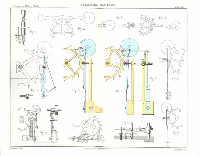
| Chronometer Escapements from Treatise on Modern Horology - Claudius Saunier.pdf |
Steffen Pahlow recommends Alois Irk's book "Der Chronometergang" in his book "Touhrbillon." Irk's book, originally written in 1923 and in German, is a complete treaty on the various types of chronometer escapements, including English and German makers. It also contains some practical information on how to make the components.
Very briefly, the English spring detent escapement functions by an escape wheel locked by a jeweled spring (i.e. the detent and locking jewel). The detent is moved out of the way by a jewel on the balance wheel (i.e. the unlocking jewel). After the escape wheel is unlocked it simultaneously is in alignment with another jewel on the balance (i.e. the impulse jewel) which the escape wheel pushes and, therefore, applies force to it to keep the balance in motion and 'in time'. The unlocking jewel is then out of the way of the detent, allowing the detent to return home and thereby locking the wheel again at the next tooth position.

I chose to use this escapement because I was intrigued by its simple elegance and precision. Also, after initially learning about horology studying only the lever escapement, upon learning about the vast number of escapements that have been created over the centuries, making a lever escapement seemed uninteresting. Also, my focus is producing the best mechanical timekeeper that I can, and this escapement has a reputation as an excellent choice for such applications. Daniels felt that it could be improved upon, at first by correcting its weakness of a passive vibration by adding a second wheel train and escapement, each functioning on opposite vibrations. Then using this two escape wheel philosophy, he created a single train movement with a double (coaxial) escape wheel and detached lever. This 'coaxial' escapement is what he is well known for, and its importance was finally accepted in Switzerland by the Omega company.
| Daniels Coaxial Escapement Patent |
To summarize some of the points in 'Watchmaking;' The spring detent chronometer escapement is not without error. The center line of the escapement is the quiescent point of the balance spring. The unlocking takes place after the center line, which is therefore a loss of energy (a rate gain). Impulse occurs after the center line which causes a rate loss. The unlocking takes place in a small radius of balance motion, therefore the energy loss is quite small. The average of these errors is therefore small.
The second vibration (the passive vibration) is without interference (except for the passing spring), therefore the period of the vibration is determined by the natural period of the hairspring. The vibration arc is 270 degrees, the total oscillation is 540 degrees. For an escaping angle of 36 degrees, the balance is free for 504 degrees.
Daniels shows drawings and provides a detailed explanation of laying out the chronometer escapement in "Watchmaking." He uses a 'chronometer wheel' in all these drawings, however, looking at his own watches that use this escapement, he used an 'English Chronometer' wheel. He describes its fabrication along with that for a regular chronometer wheel. No explanation, as I can recall, of their specific attributes.
I therefore sketched a scaled drawing of the spring detent escapement at the moment of unlocking, in a from-the-top orientation and with an 'English wheel.' This drawing can be found below as a PDF.
| Earnshaw Detent Chronometer Escapement with English Wheel |
Also, for my own understanding of this escapement, I drew the process at various critical stages with minimum confusion of dimensions, etc. This drawing can be found in the following PDF file.
| Earnshaw Escapement at various stages |
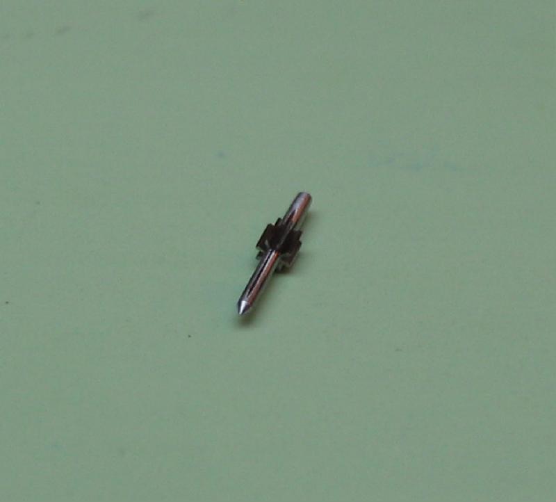
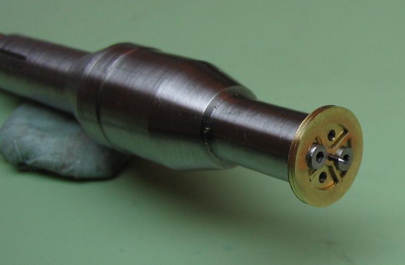
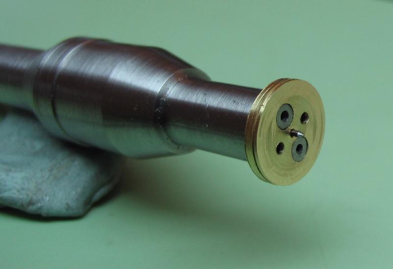
Escape Wheel Pinion
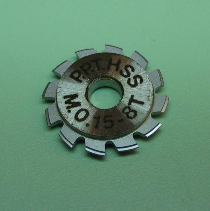
The escape wheel pinion mates with the fixed fourth wheel, which is 0.15 Module. To achieve the correct ratio (10:1), the fourth wheel is 80 teeth and the escape pinion is 8 leaves. A 0.15M x 8T cutter was purchased from P.P. Thornton.
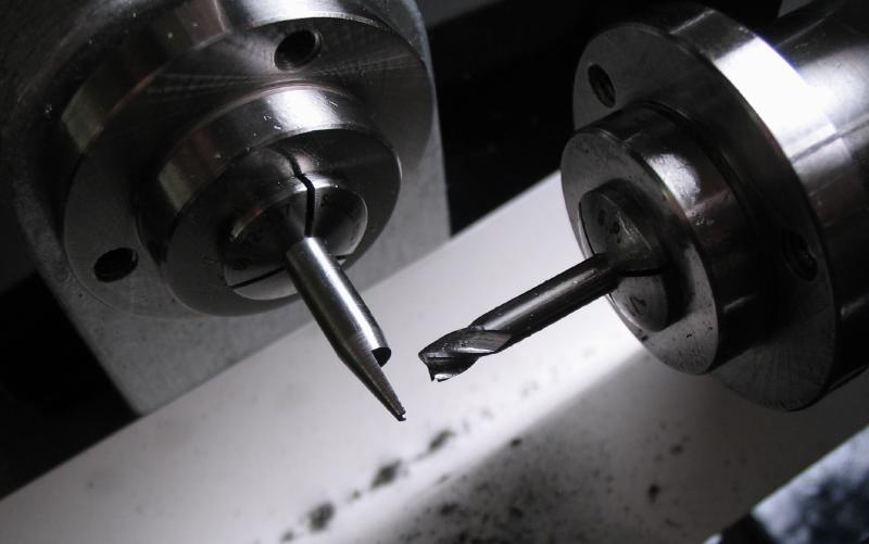
To begin the escape wheel pinion I made a hand drawing of the basic dimensions for the blank. The blank was turned to diameter and a center turned on the end. It was turned from 1/8" O-1 drill rod. The surface was coated in blue ink to help visualize the progress of milling the leaves. The arbor diameters are oversized and will be reduced later.
| Escape Pinion - rough dimensions |


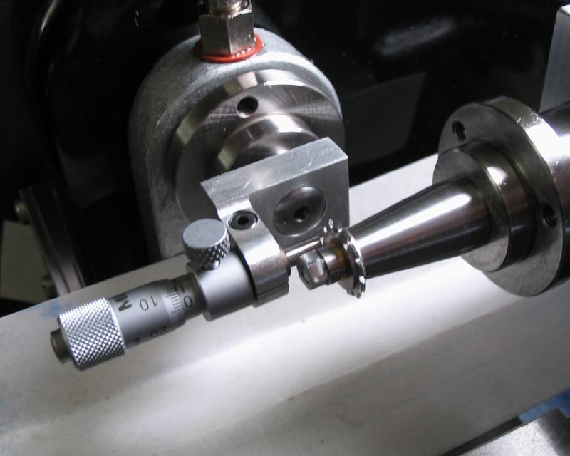
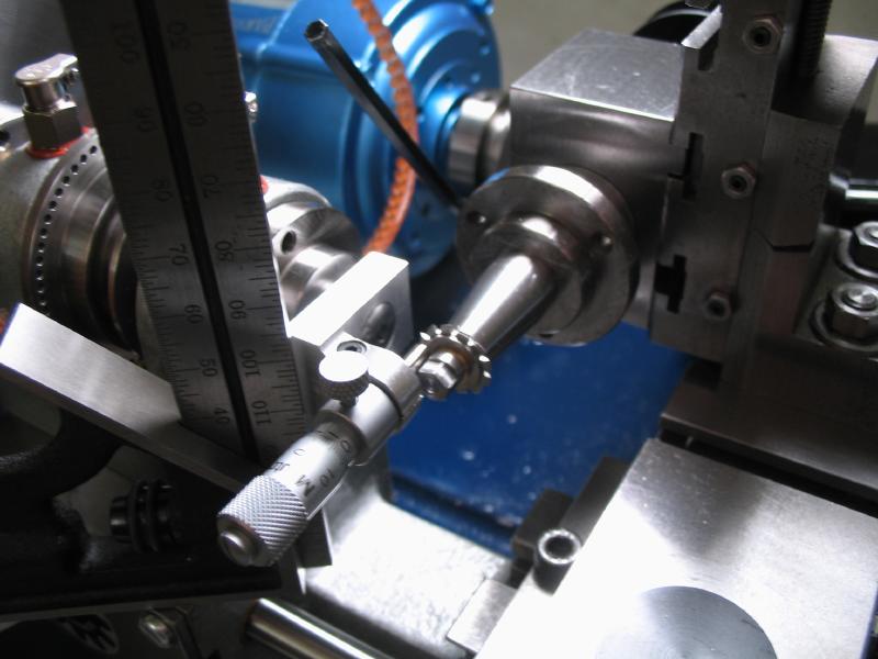
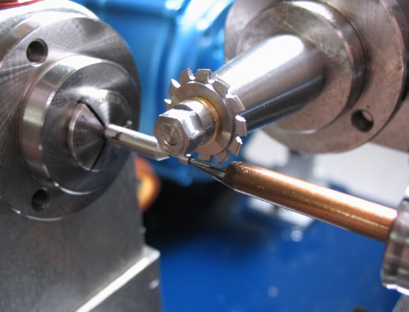
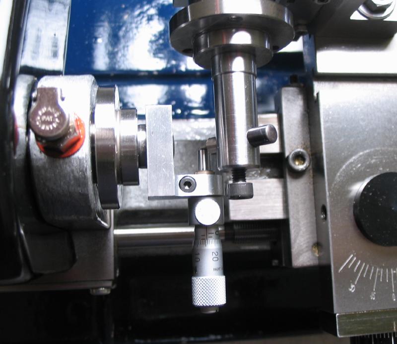
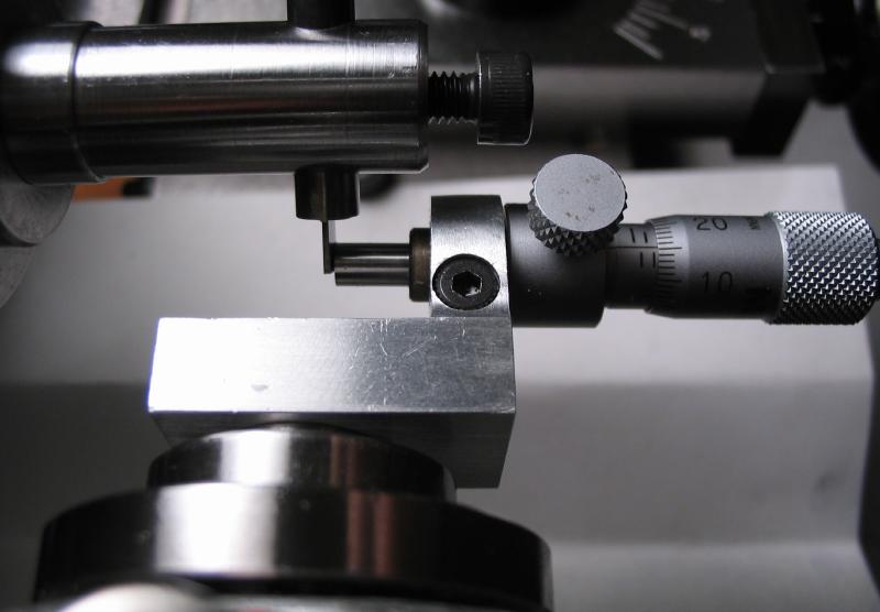
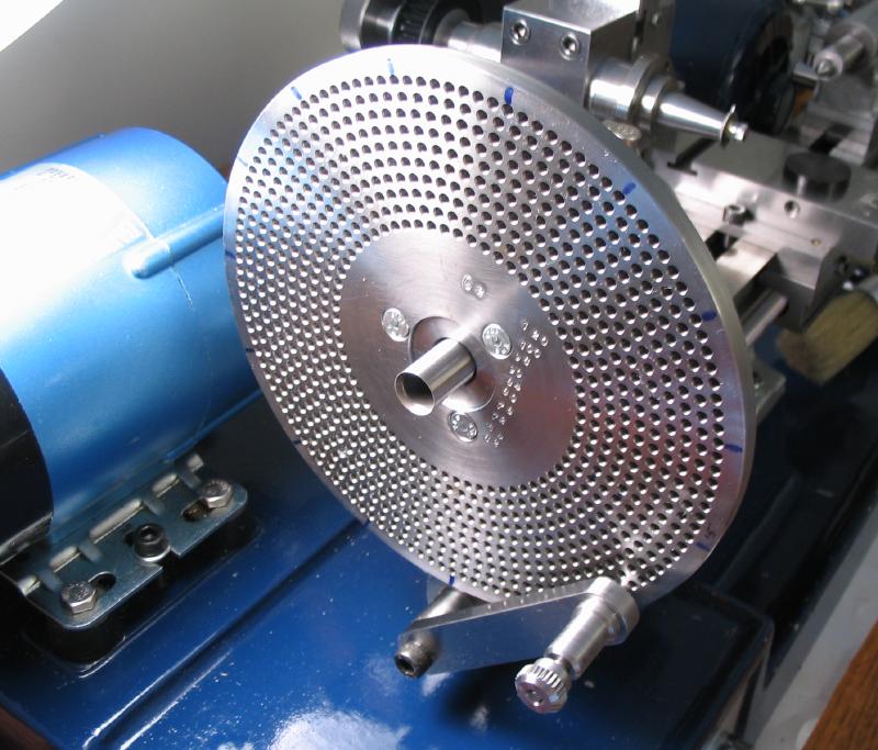
A couple setup photos are showing the centering of the cutter and the pulleys setup for the slowest speed, etc. The leaf count is 8, which is not divisible into 60, so the index plate was used, I decided on 120 divided by 15 to give 8 steps.
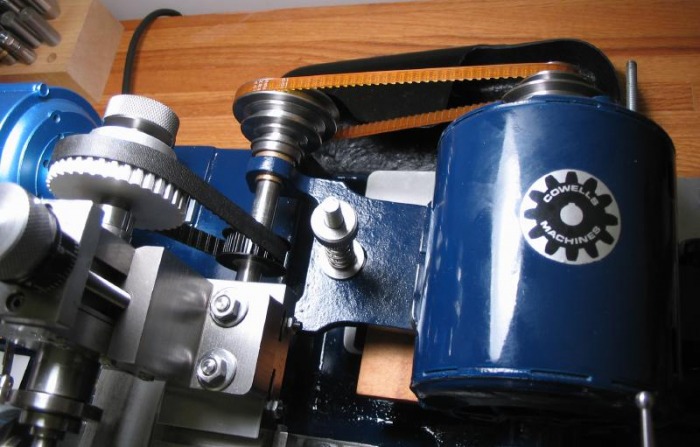
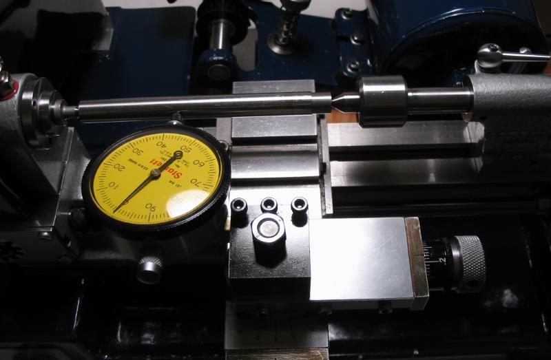
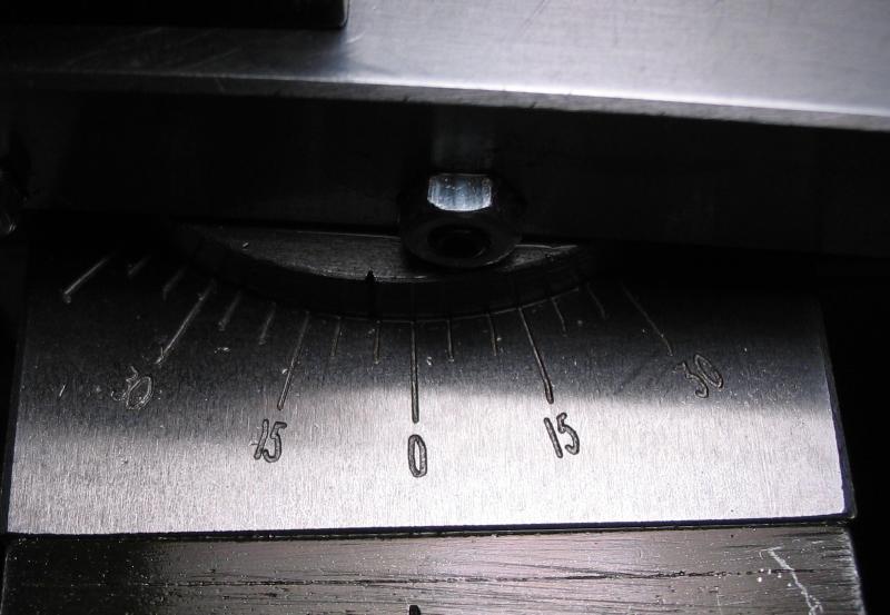
The cutter is centered using the micrometer setting tool. The thickness of this cutter is slightly off specification, measuring 2.115mm. After experimenting, the teeth are on center, therefore the micrometer was set to as close as possible to 1.058mm (0.01 graduation). A quick method I learned is to square the centering tool with a square using the headstock mounting surface flat, and with the micrometer set, the milling spindle is loosened in the mounting block and slid forward to contact the micrometer face. The mounting block is then tightened.
 |
 |
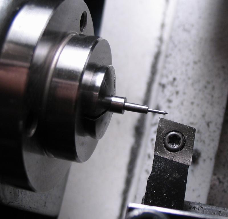
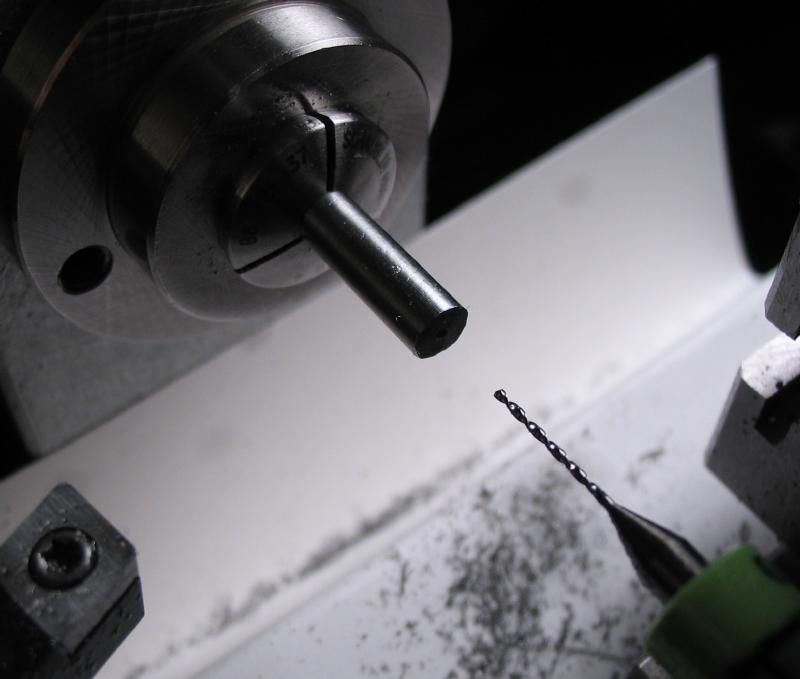
The work is supported on a tailstock mounted bed. This was made from 4mm O-1 drill rod, drilled 0.60mm and 0.65mm on opposing ends, and tapered.
 |
 |
The ends were then milled to just less than half.
It was hardened in oil and tempered to a brown color.
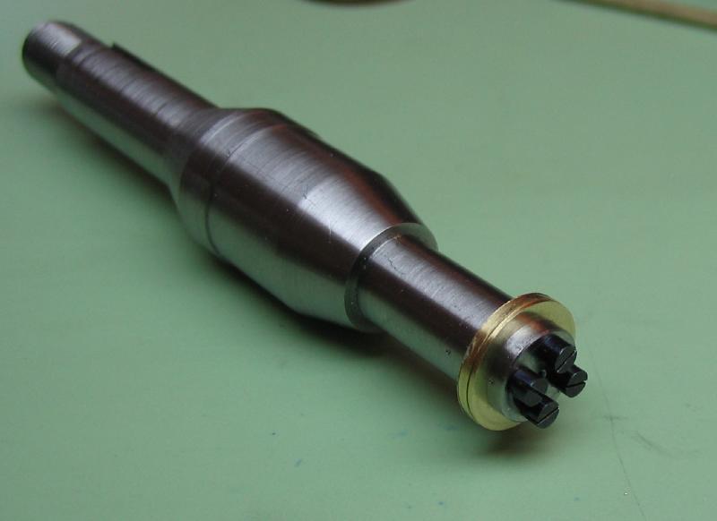
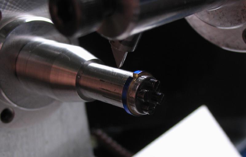
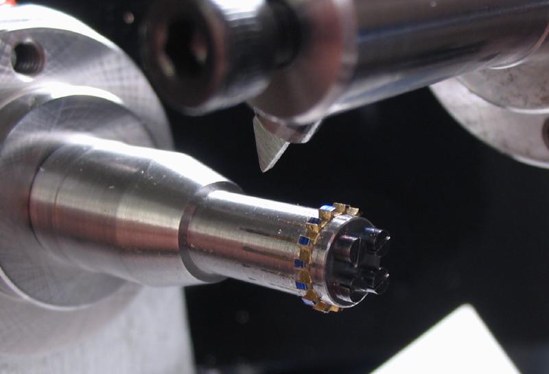
The leaves were cut in three passes.

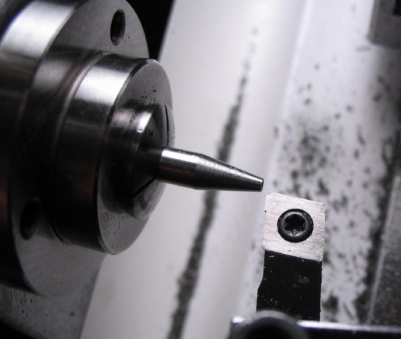
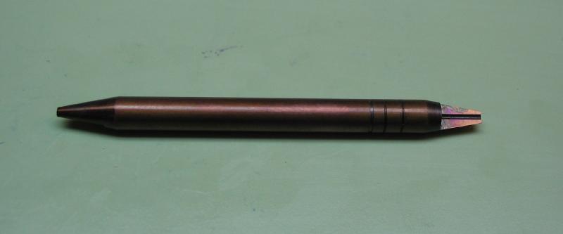
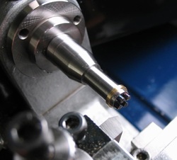
The rough pinion is then parted off with a sharp point graver to roughly form a center.
 |
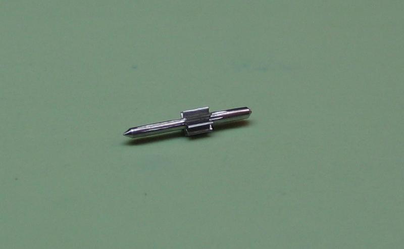 |
It is then loosely bound in iron wire for hardening. Following this, it is was tempered to a blue color.
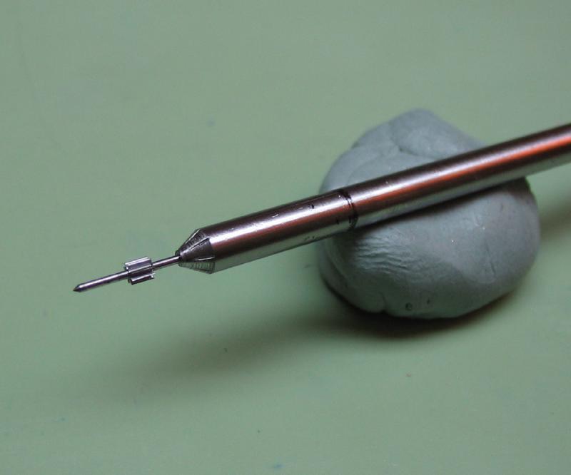
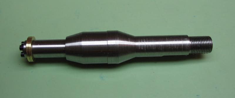
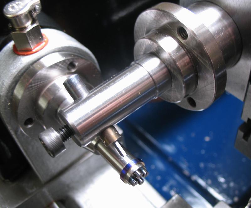
The pinion was then secured in a collet on the lathe, and trued with the face of the graver against the leaves before lightly tightening the drawbar. Daniels provides a description and illustrations of this procedure in the "Turning" chapter of "Watchmaking." After truing, the center is assured by turning with the graver and the arbor trued by turning as well. The pinion is then reversed and the process repeated. Afterward, the leaves can be polished with Simichrome on a boxwood polisher.
At this point the pinion is useful for depthing with the fixed fourth wheel, which is covered in the Tourbillon carriage section.

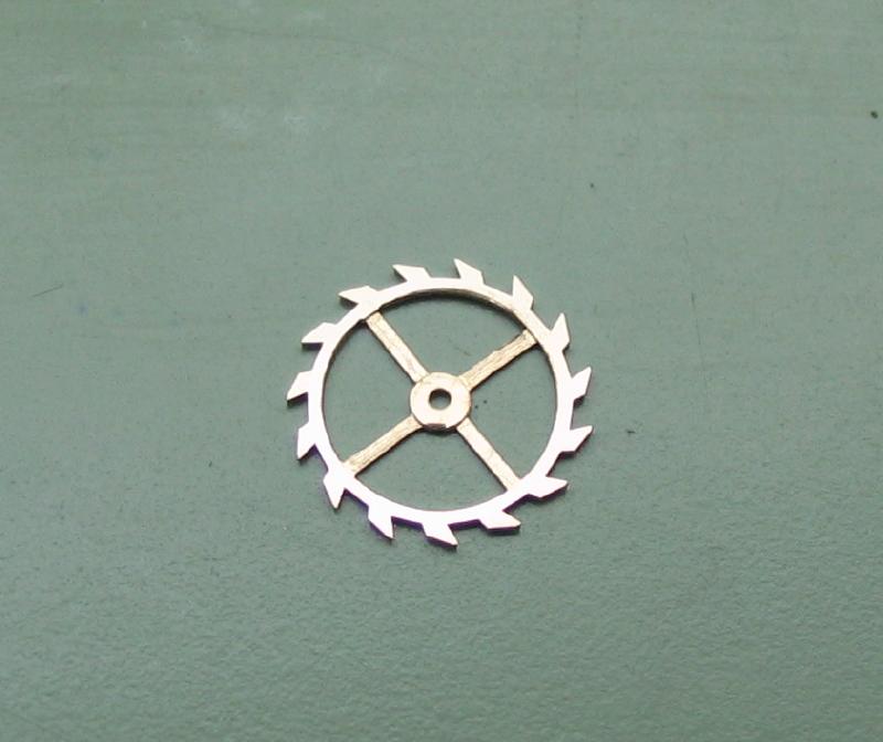
The Escape Wheel
The blanking and cutting process I am following is described by Steffen Pahlow in his book "Touhrbillon." I describe the book above on this page, and in the bibliography. Pahlow uses gold to produce his escape wheels. The natural properties of gold make it a good candidate for escape wheels which receive constant blows from the escapement jewels. Daniels mentions the use of gold, however, rejects it for adding unnecessary weight and used brass wheels instead.
Obviously there is a significant difference in cost, and if Daniels was able to successfully use brass, then I am willing to accept the cost reduction! I plan to use rolled brass sheet, which has a good spring directly from the package. A rolling mill would be useful to freshly work harden a larger thickness sheet to the required thickness of wheel. Pahlow describes work hardening gold sheet with a planishing hammer in a prescribed motion. This is a traditional goldsmith technique. The resulting surface of the sheet is uneven and must be faced or ground flat.
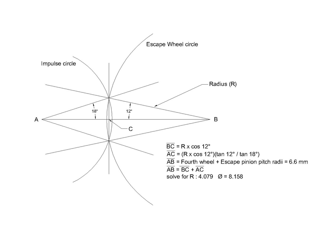
Finding the actual diameter of the escape wheel is dependent on the watch at hand. The center distance is 6.6mm, this is calculated from the fourth wheel and escape pinion pitch circle radii. The fourth wheel is concentric to the balance and the escape pinion is, of course, concentric to the escape wheel. The escape wheel diameter can be arrived at by trigonometry. The intersections of the impulse circle and escaping circle can be bisected to form right triangles; the known center distance together with the escaping angle and impulse angle can be used to calculate the unknown wheel radius (R).
(R cos 12) + (R cos 12)(tan 12 / tan 18) = 6.6
R = 4.079024 ; therefore the wheel diameter = 8.158
Another way to go about it is to use vector based computer drawing; earlier on this page I attached a CAD drawing of the basic escapement dimensions, the center distance of balance to escape wheel center was chosen arbitrarily. The dimensions are universal as they are angular relationships. Below is an update using the same drawing, but rescaled using a center distance of 6.6mm. 'Measuring' the resulting wheel diameter in the drawing, which AutoCAD can do with ease, resulted in an escape wheel diameter of 8.158mm. I recall that Daniels specifies an example diameter of 9mm in several places, however, he was not using PP Thornton cutters.
| Escapement Drawing - Rescaled |
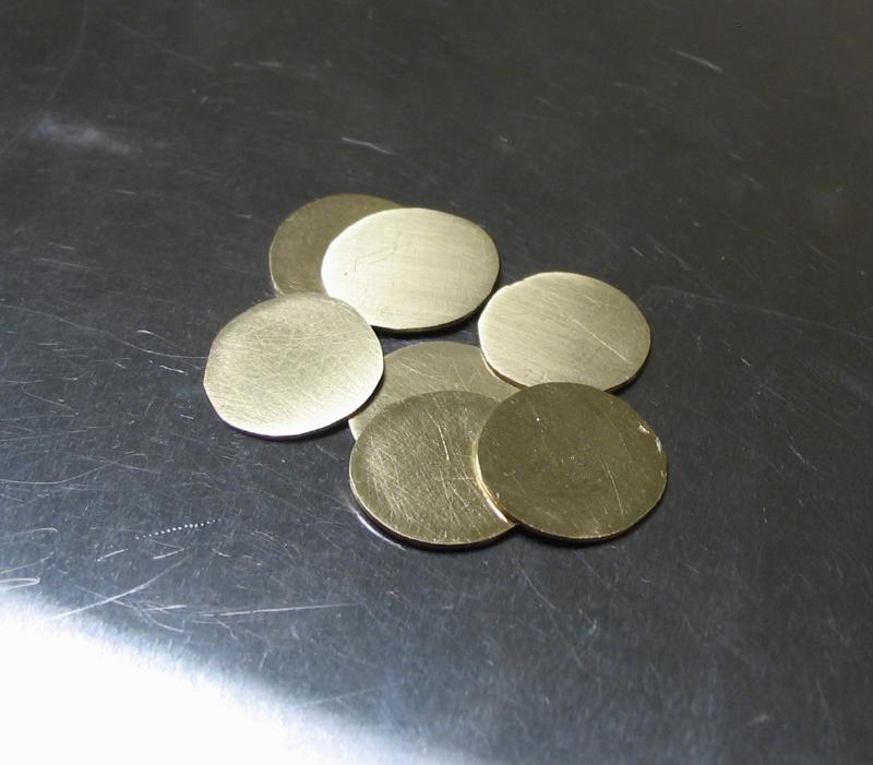
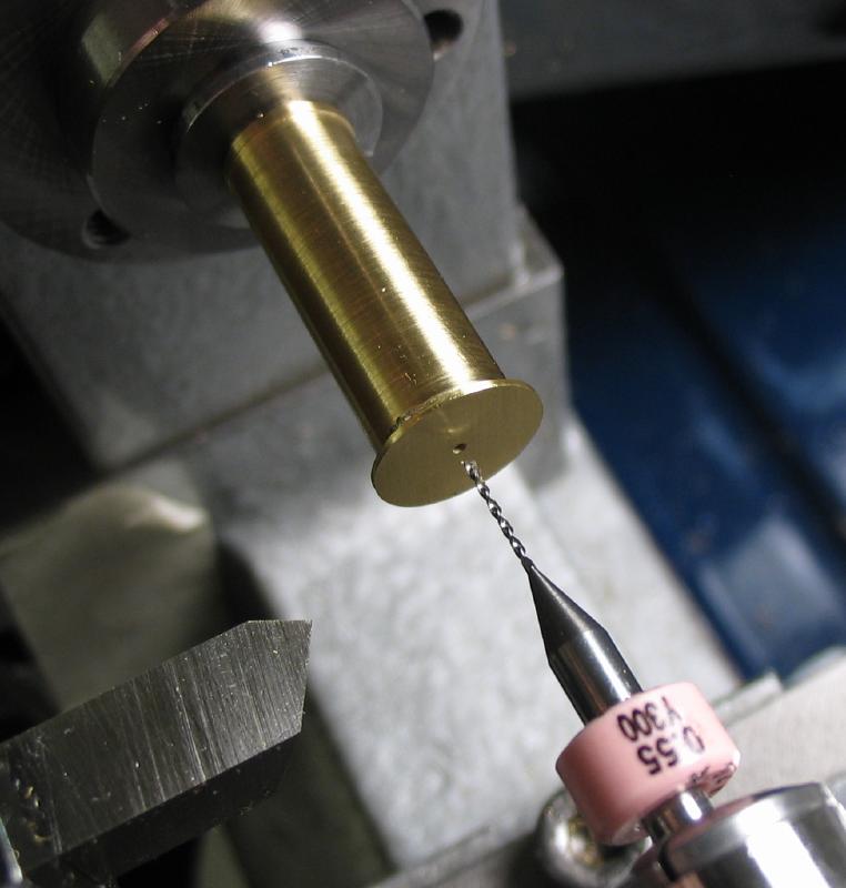
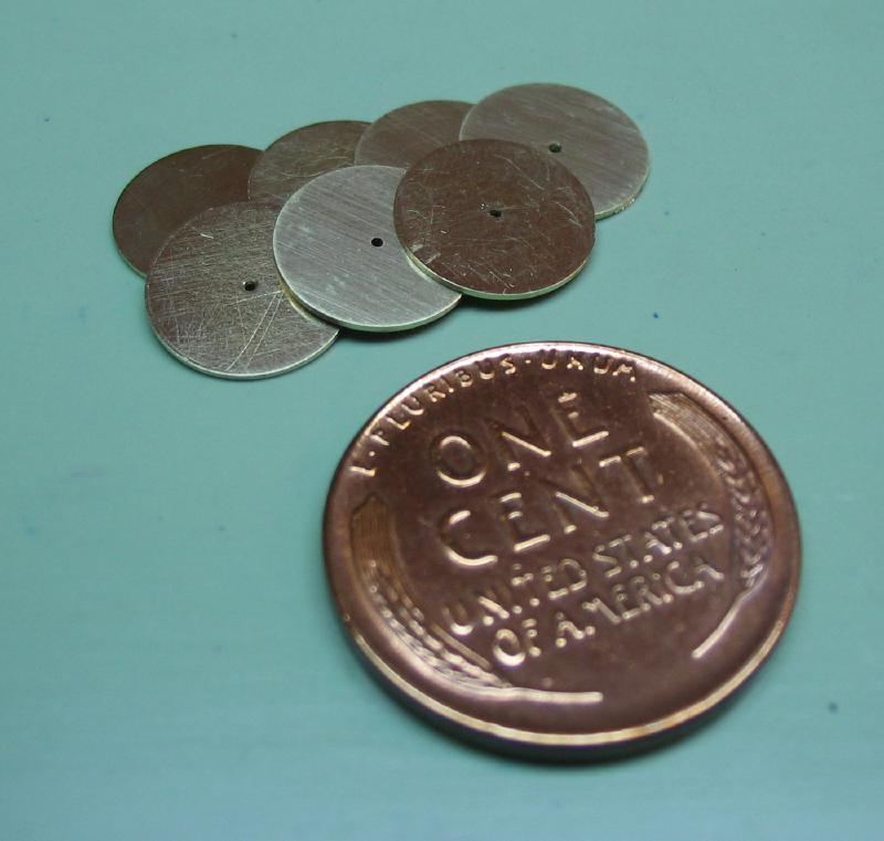
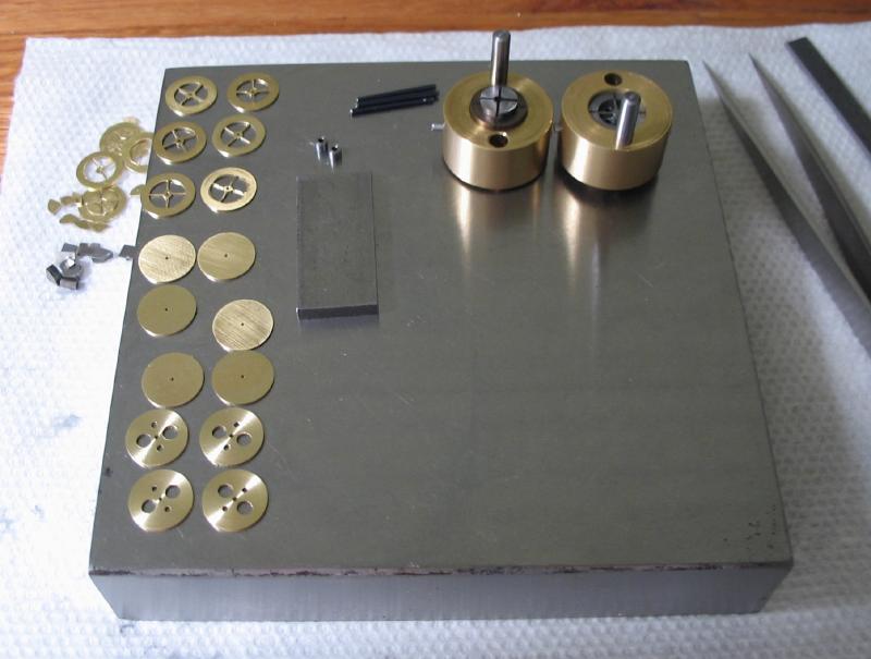
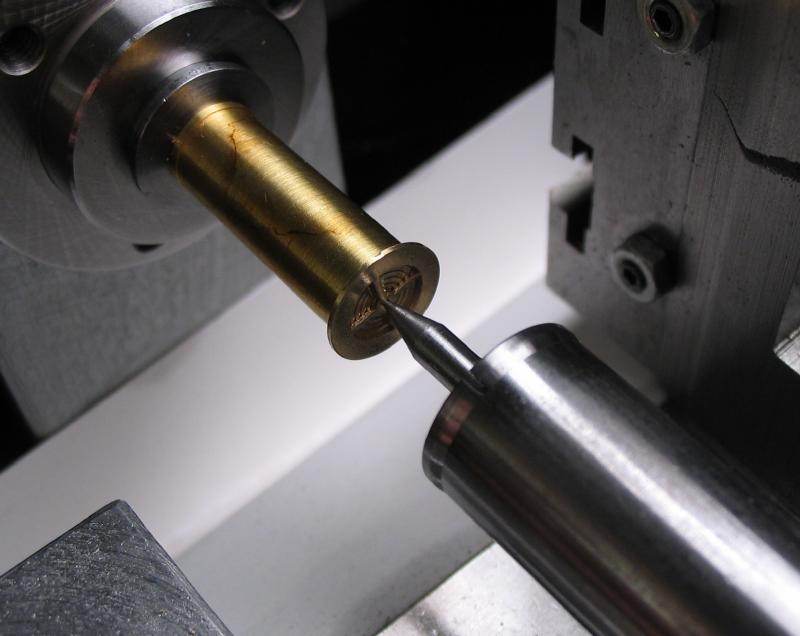
The brass blanks are sawn from 1/64" flat strip and brought to diameter on a cement arbor. While mounted they are center drilled, and drilled 0.55mm. After removal, they are lightly papered with 600 grit emery.
The rough blanks after sawing out.
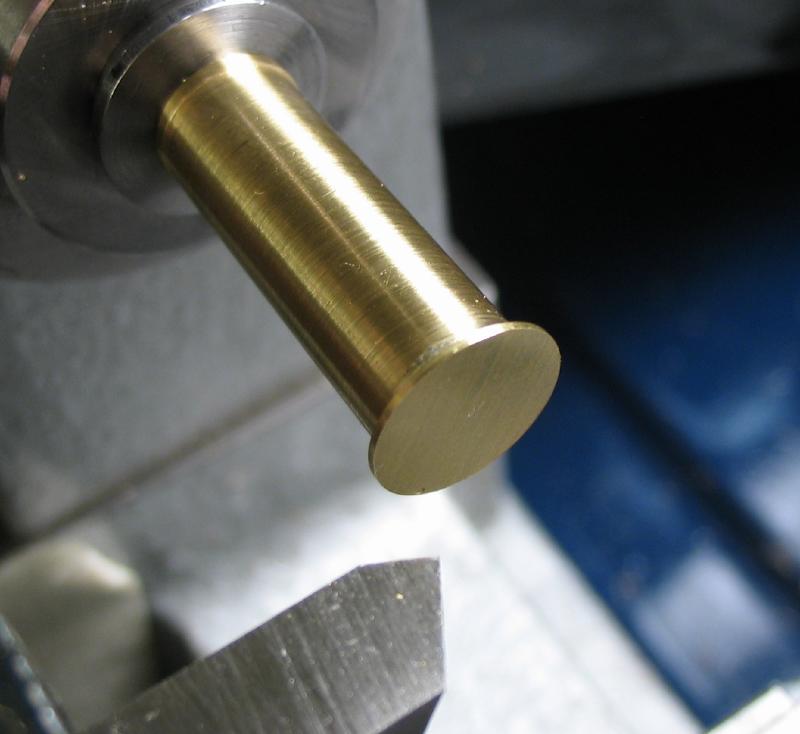
The blank is adhered to the arbor with cyanoacrylate glue.
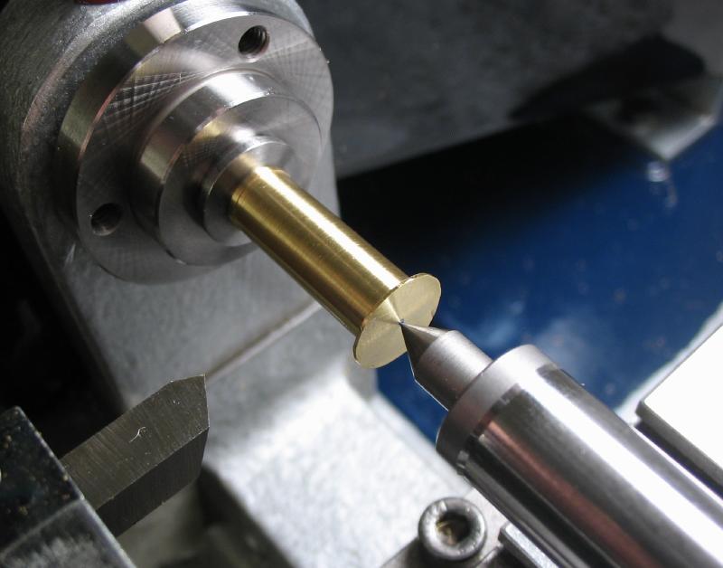
Turn to 9.5mm
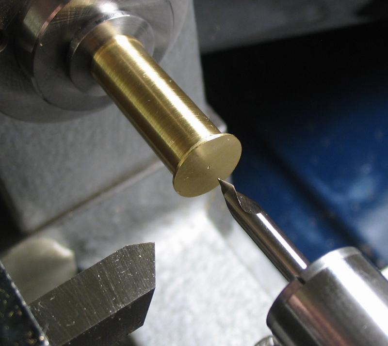
Center drill and drill 0.55mm.
 |
 |
Repeat . . .
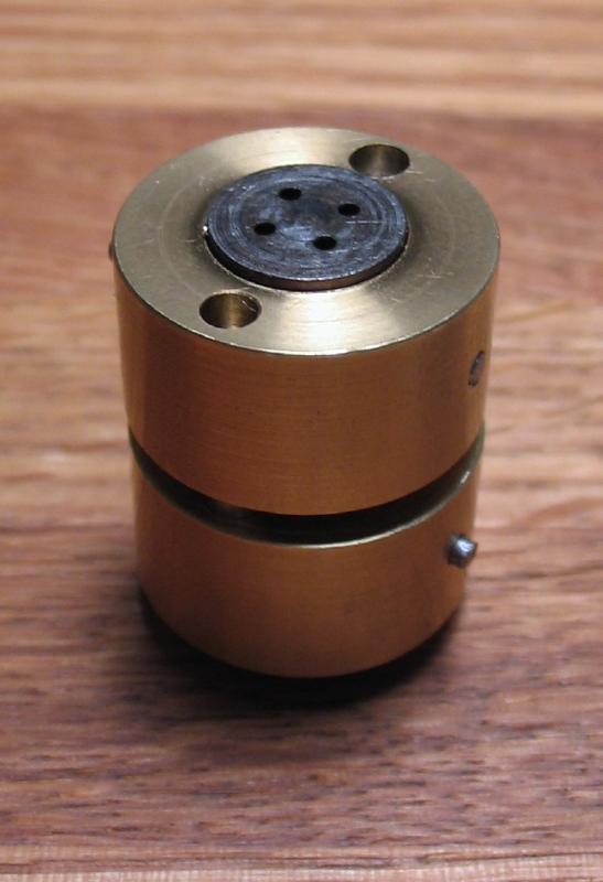
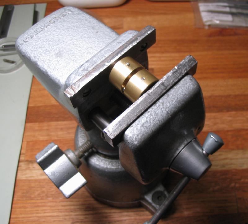
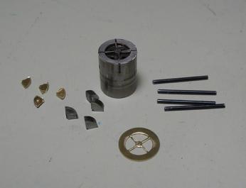
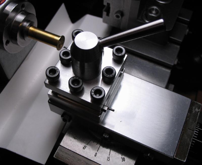
The stamping die setup is used to punch out the crossings. A blank is placed into the lower section recess. The punches are positioned into the spaces in the upper die. The two halves are assembled and mounted into the vise. The vise is used to apply the necessary force to drive the punches through the wheel blank. A mechanical or hydraulic press would, of course, do nicely, but my small bench vise does the trick. I would at least recommend a larger vise.
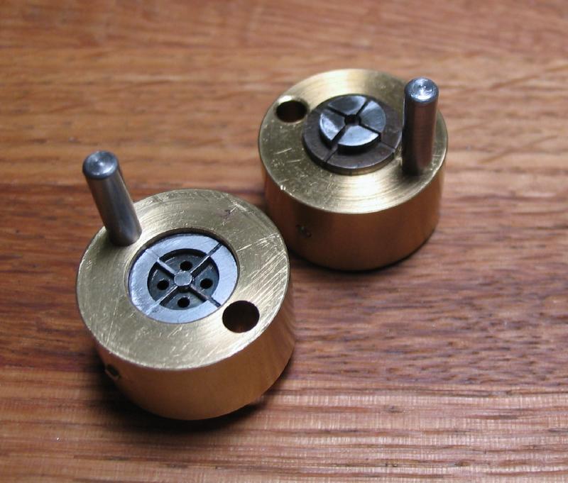
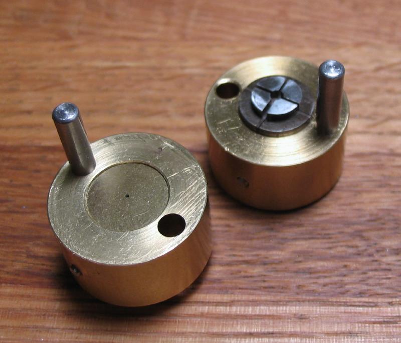
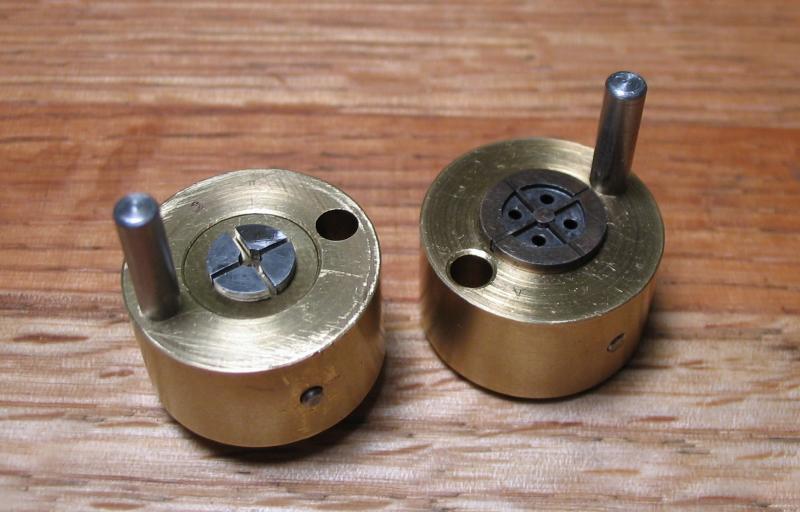
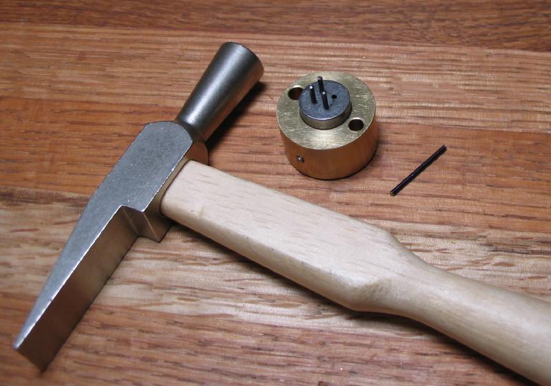
The halves are separated and the punches tapped out using the blued steel pins inserted into the four holes.
Takes some practice ...
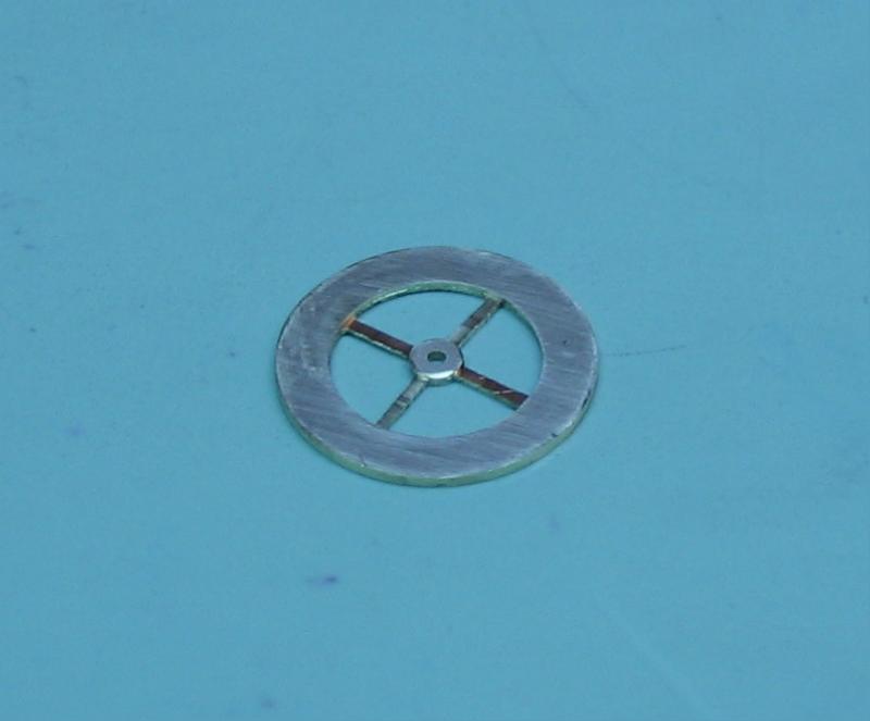
The punches round over the brass as they cut through. To remove the rounded surface of the crossing the wheel can be recessed. This is advantageous because it reduces the weight of the wheel, and is a common practice to do so.
The wheel is mounted back on the cement arbor, and right and left hand boring tools are used to turn down the arm portion of the crossing. The roundness of the center hub can be restored as well.
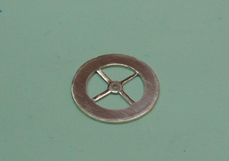 Top side - note rounded surface from punches |
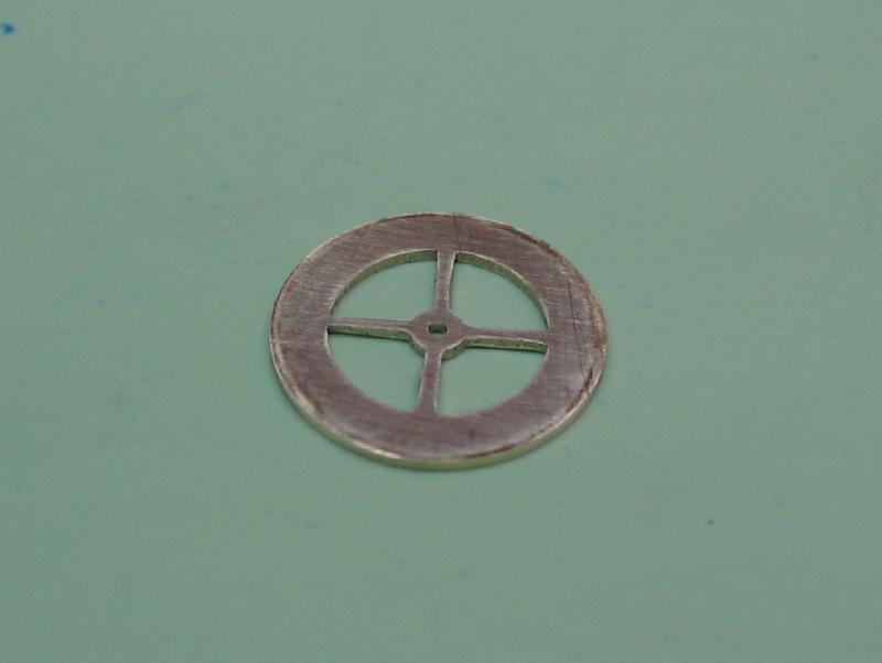 Bottom side - still flat |
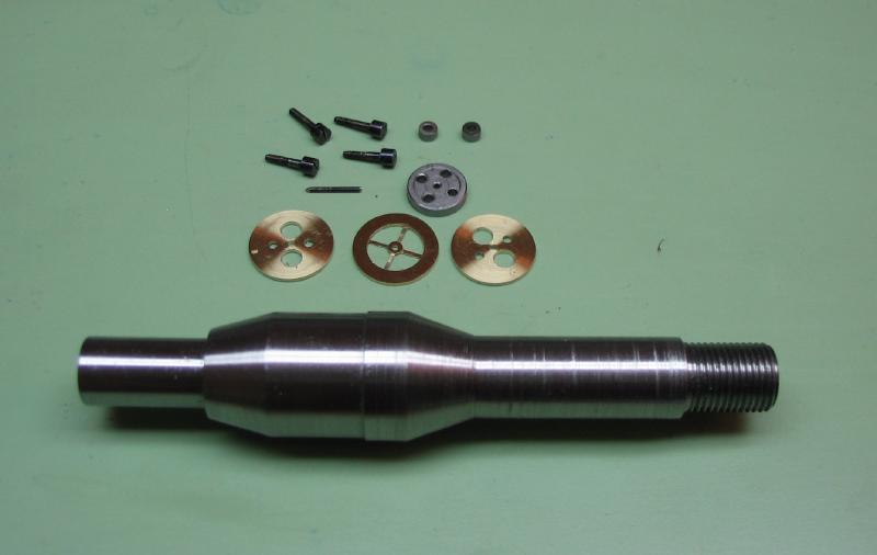
A wheel blank sandwiched between two sacrificial blanks is mounted on the blued steel center pin. The steel spacing washers are inserted through the wheel blank crossing and into the drilled holes of the sacrificial blanks. This assembly is mounted onto the arbor and the retaining washer attached and the four screws installed. The resulting fixture is ready to be mounted on the lathe for completing the wheels

The blanks are turned to the finished diameter of 8.158mm*.
* Turning a part to a thousandth of a millimeter is easier said than done. It requires a sharp tool and a means of measuring to this accuracy as well, i.e. a thousandths reading micrometer. Also, if advancing the cutting tool with the cross slide one will meet with the limitation of the hand wheel graduation. The leadscrew dials on the Cowells are graduated to 0.02mm, and one can easily estimate 0.01. Obviously, if turning to an accuracy of 0.001mm, this presents an difficulty. A machinist trick/technique is to use the compound slide to advance the cutting tool by very small increments. This technique is, perhaps, widely known or obvious, but I read about it in Harold Hall's books, "Model Engineers Workshop Projects (Workshop Practice Series No. 39)," and in more detail in "Lathework, A Complete Course (Workshop Practice Series No. 34)." Basically, if you envision the topslide as the hypotenuse of a right triangle, and the side adjacent as the lathe center-line, the in-feed will be the side opposite. Therefore if set to a specific angle, top slide movement will have a resulting in-feed which is reduced by a calculable amount (the sine of the angle is the ratio of reduction). Mr. Hall specifies 6 degrees (or 0.6 degrees), however, from my own understanding: The topslide leadscrew has a 1mm pitch, by setting the top slide to 5.74 degrees the in-feed rate is reduced to 0.1mm, if set to 0.573 degrees, the feed is reduced to 0.01. Effectively, the 0.02mm graduations can be reduced to 0.002 or 0.0002mm! Accurately setting the angle then becomes the tricky part.
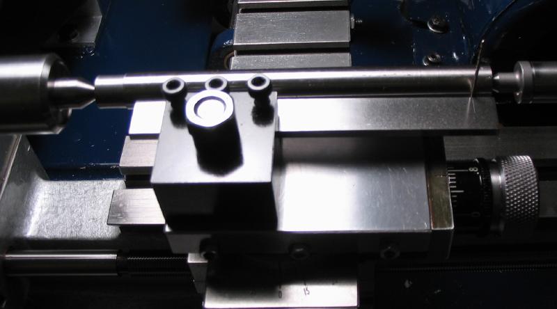
First, the tailstock is accurately centered for zero offset using the test bar, as described on the maintenance page. The test bar is set between centers. The top slide must be accurately set to zero degrees. The dial gauge is mounted in the toolpost. A special holder was made (described on lathe maintenance page). The compound slide is adjusted until the dial gauge remains unchanged while feeding the topslide to and fro.
A rigid gauge was made from steel bar. It was scribed 100mm from each end using the combination square.
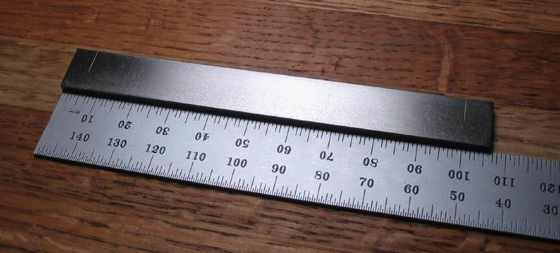
The gauge is mounted in the tool holder, and set against the test bar (by swiveling the toolpost, not the slide). Essentially a sine bar is to be created, the angle can then be set by inserting a pin between the gauge and test bar to offset the desired angle. A 1mm drill bit at 100mm will give the angle needed for the 100:1 reduction, or a 10mm piece of drill rod for 10:1.

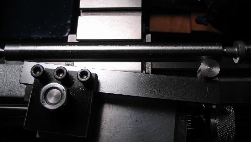
The 10mm drill rod for 10:1 is 5.74 degrees, and is confirmed looking at the angle graduations. However, the 100:1 reduction proved very useful. A half turn of the compound slide (0.5mm on dial) is only 0.005mm of feed, which reduces the diameter of work by 0.01mm.
At this point the lathe is setup for milling the tooth spaces. Details on the cutter shapes and offsets, etc can be found in the attached PDFs below. Details on making the cutters are also discussed on the toolmaking page. This wheel is certainly the most challenging part I have made thus far. I experimented with different cutters and speeds and feeds. I got quite good at making the wheel blanks, which must be done prior to cutting the teeth.
Drawings of the various cutters.
| Cutter Profiles |
| 5mm Fly-cutter - Gashing |
| 5mm Fly-cutter - Radius |
The gashing cutter is set to its required offset, calculated as 1.659mm, the centering micrometer set to just a hairline below 1.66mm.
 |
 |
The blanks were colored blue with a Sharpie marker to help visualize the progress. Indexing was provided by index plate, I chose the count of 120 ÷ 15 = 8.
The gashing cutter is lowered 0.68mm and run at medium belt speed
(1100 RPM for 110 volt model).
The wheel is advanced by indexing through 15 cuts to full depth.
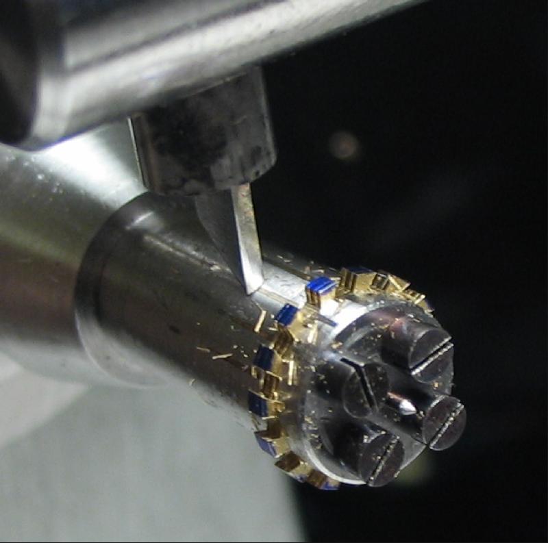
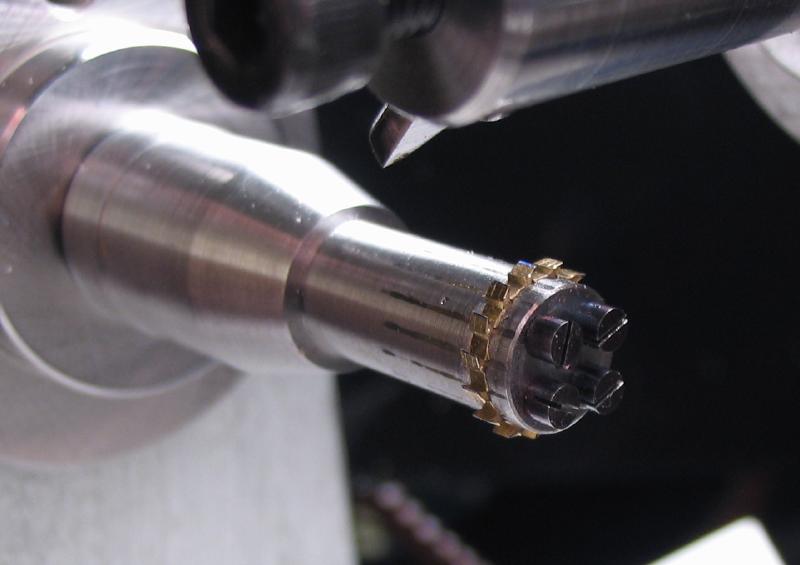
The radius cutter is installed and adjusted so that only a hairline of blue remains at the tip after cutting the back of the tooth. This radius cut is repeated for all 15 teeth.
 |
 |
