
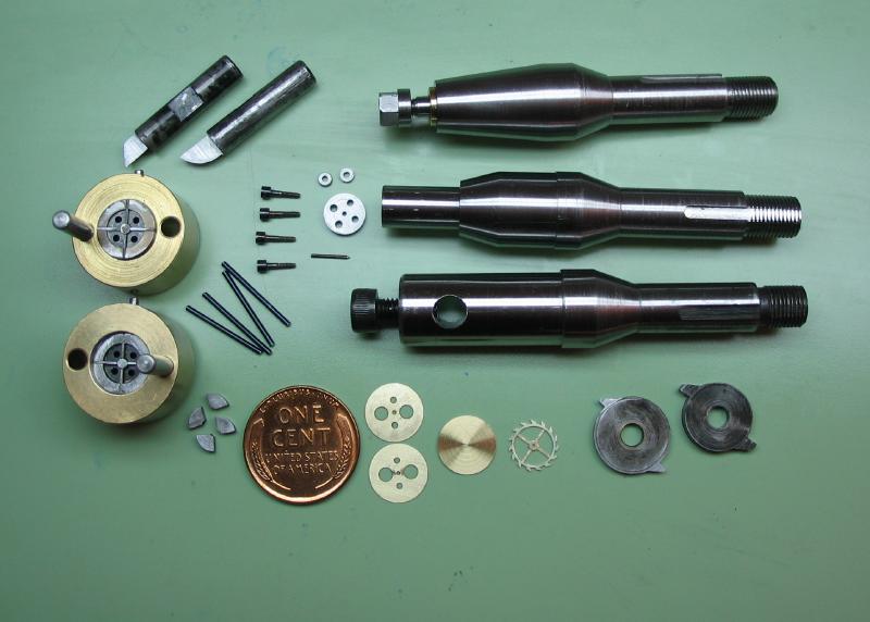
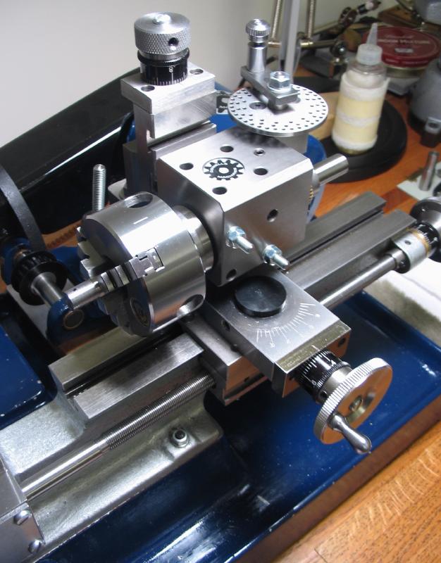
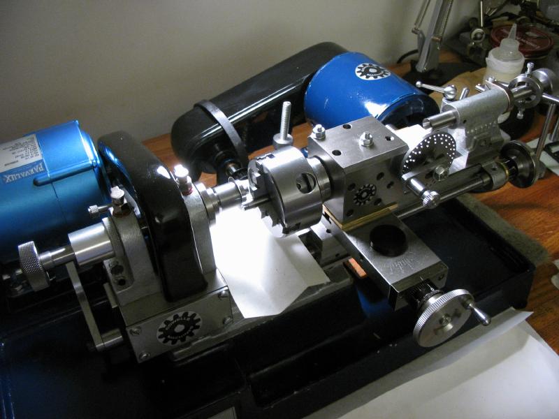
Escape Wheel Tooling
The tools described on this page are for making an English-style chronometer escape wheel. This involves making a number of different arbors, punches and dies, cutters, etc. Total time to make the components on this page was approximately 120 hours, of course, I tend to work slowly and this total includes remaking several parts as well.
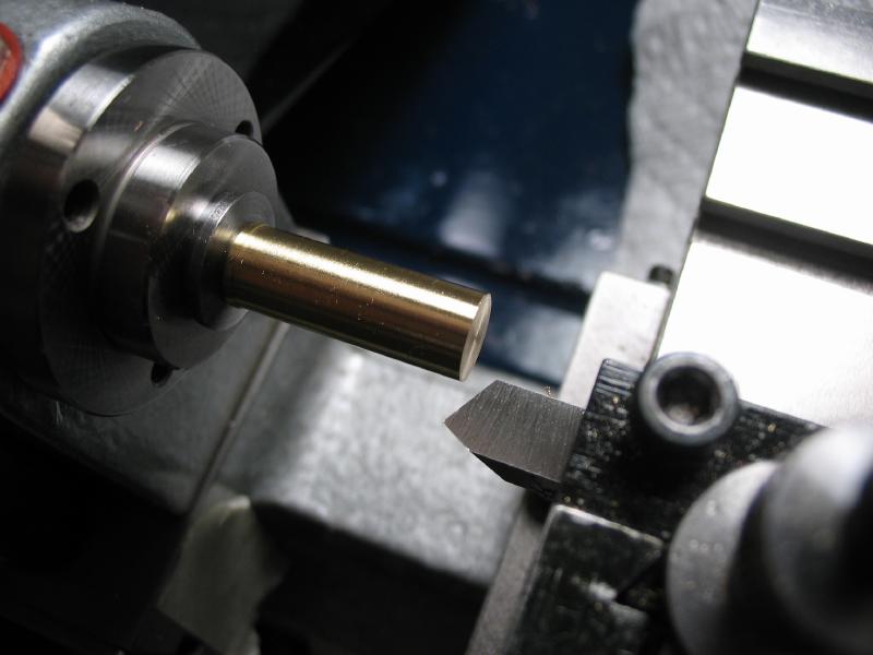
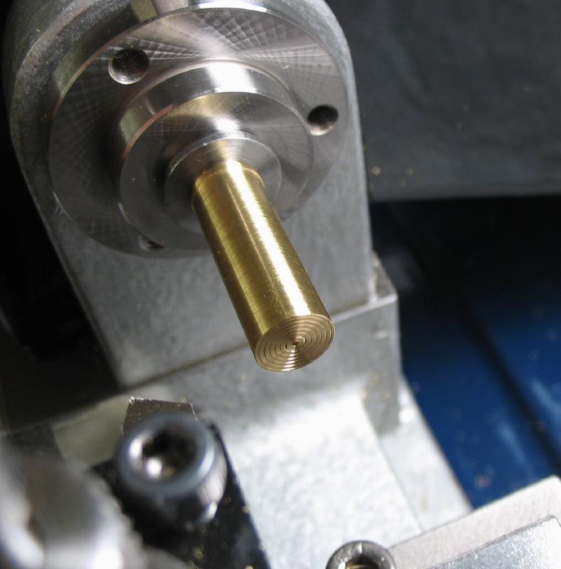
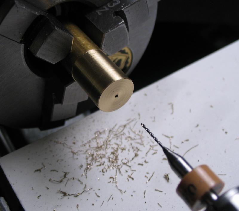
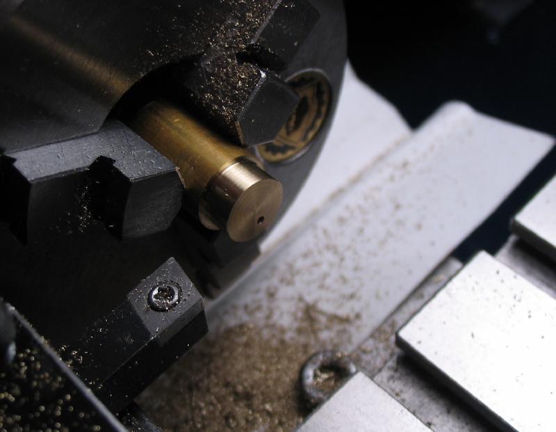
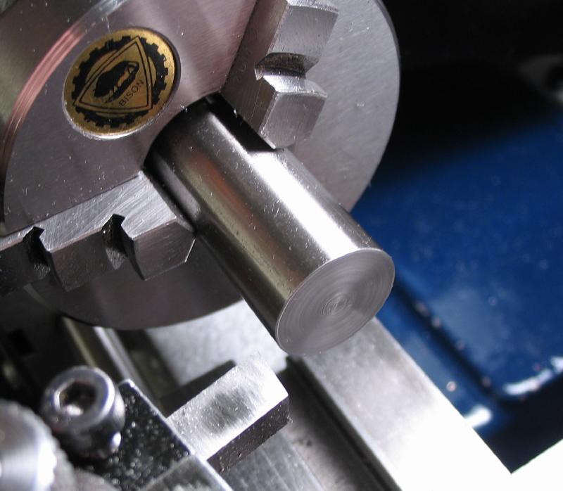
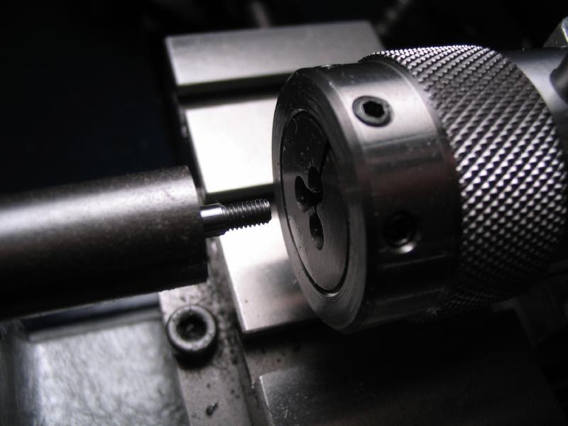
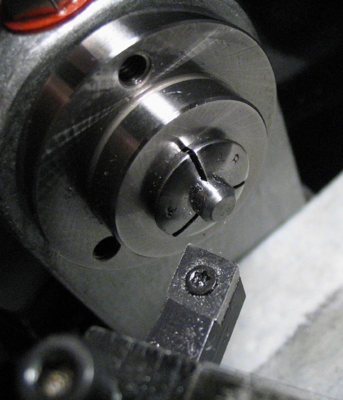
Cement arbor for sizing blanks
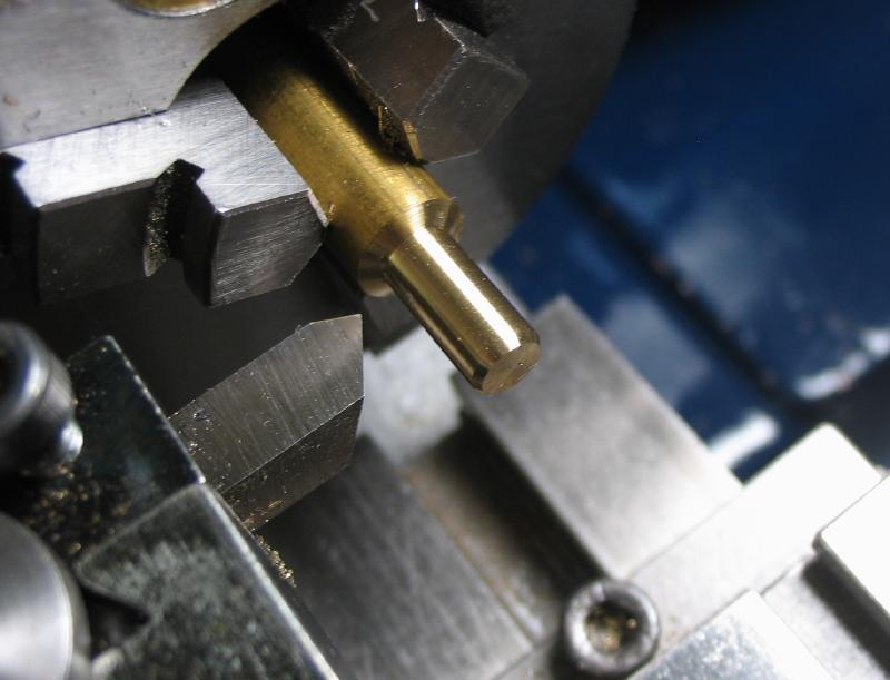
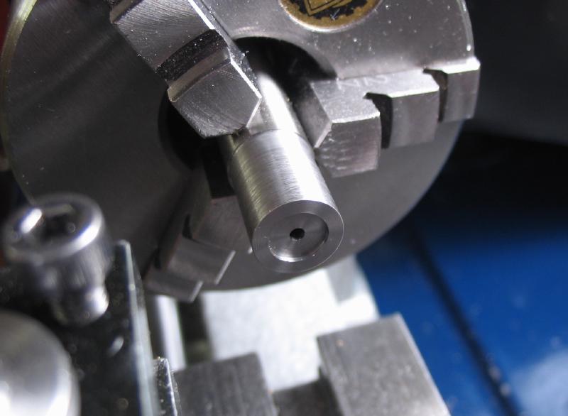
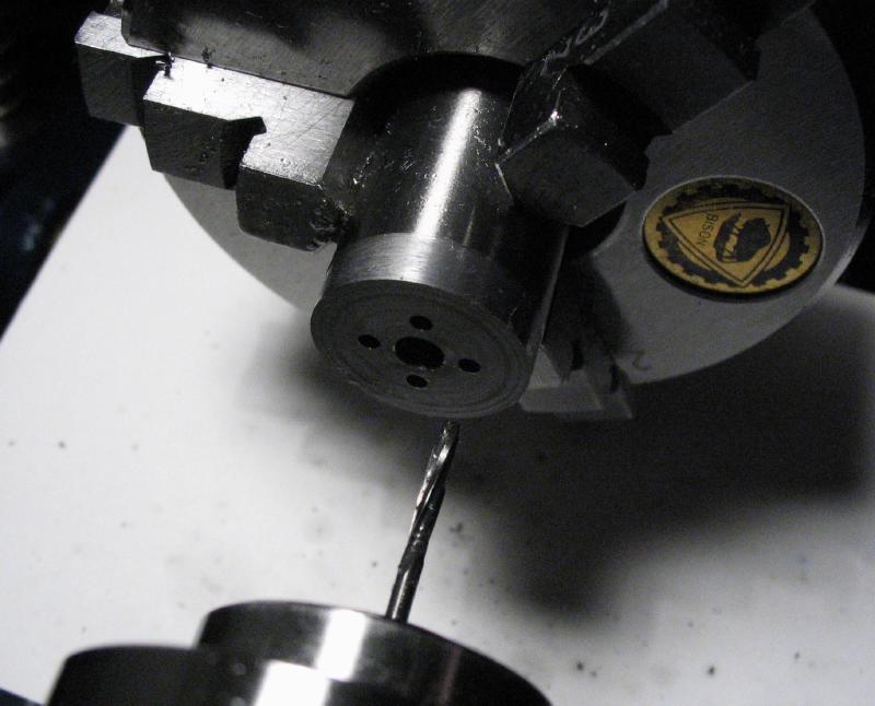
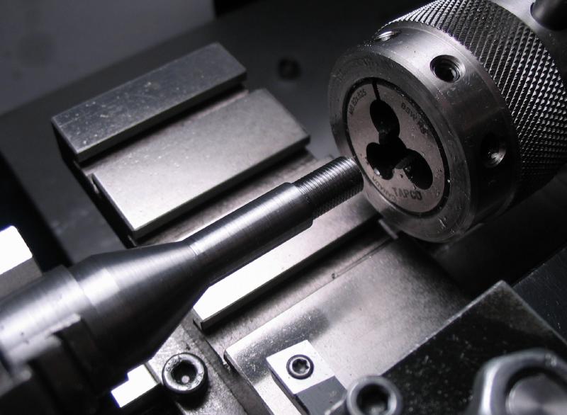
An arbor was made to hold the brass wheel blanks. They can be brought to their initial diameter of 9.5mm to fit into the stamping die and to be center drilled. The arbor is made from 5/16" brass (360) rod. It was turned down to thread M5x0.8. It was then mounted in the collet holder and faced and grooved.
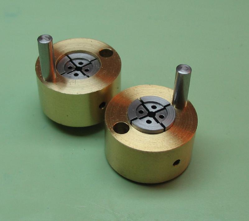
Wheel Blank Punch
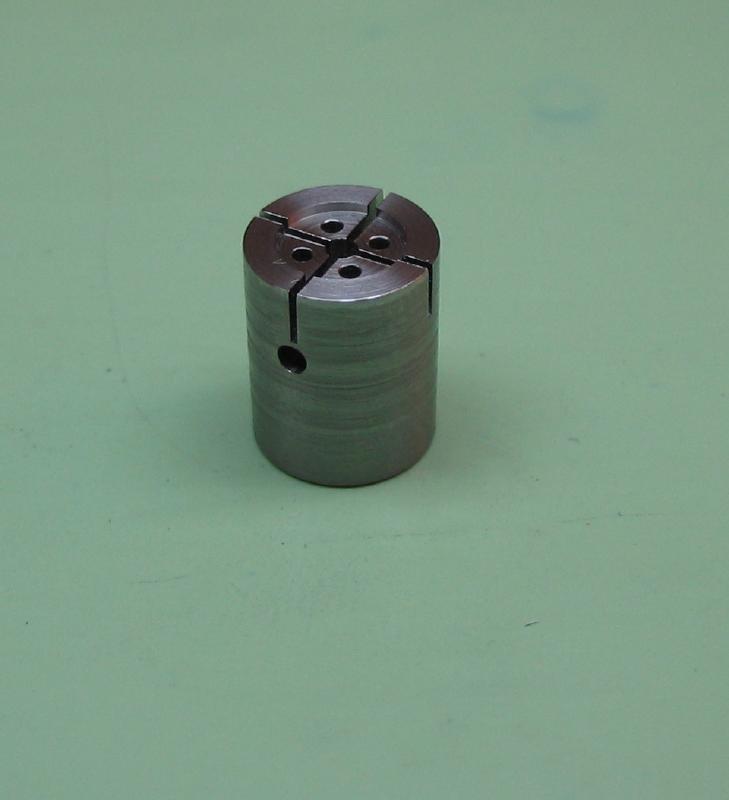
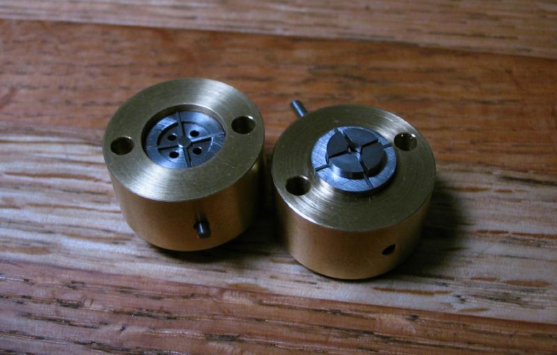
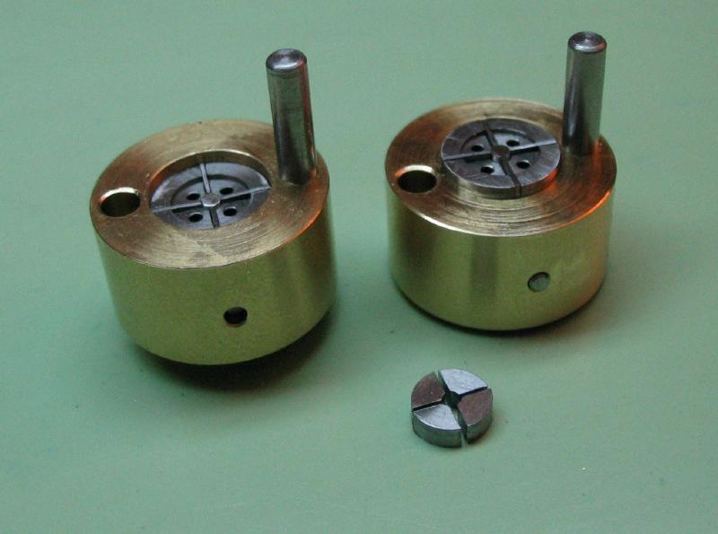
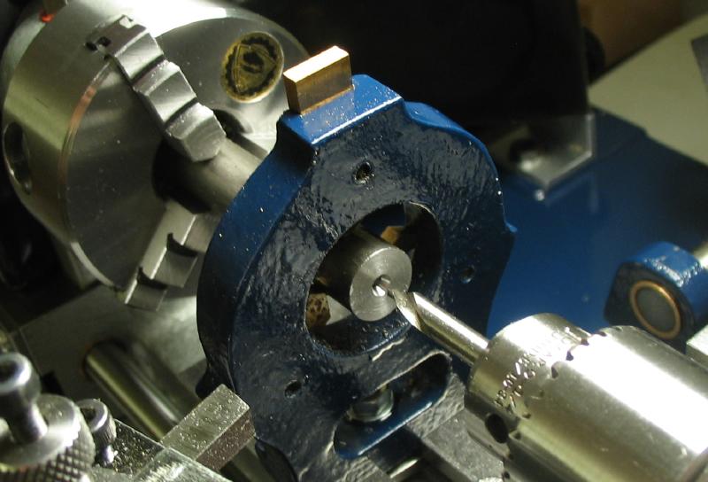
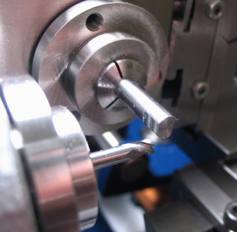
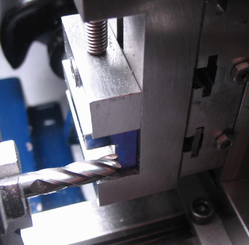
The escape wheel is too small to cross out with a piercing saw and files. Instead the wheel is punched out to shape and then the teeth milled into the circumference. The punch and die consists of two halves. There is two steel guides that have the shape of the wheel and position the punches through the blank disc. There is also two brass frames to keep the guides correctly oriented.
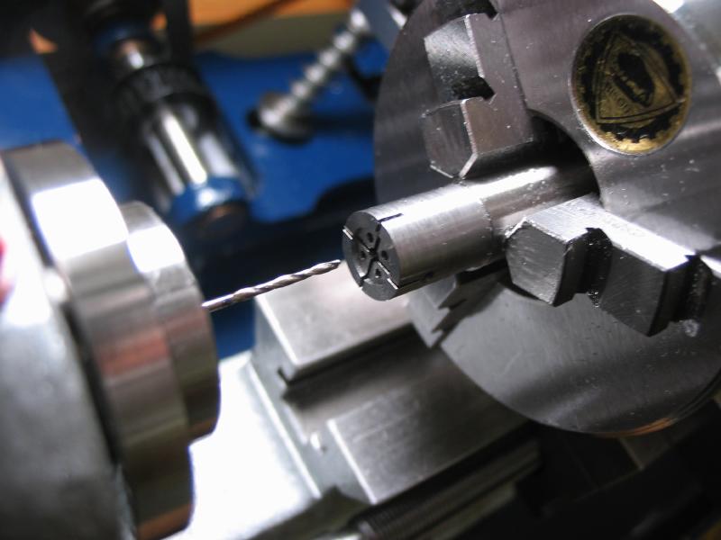
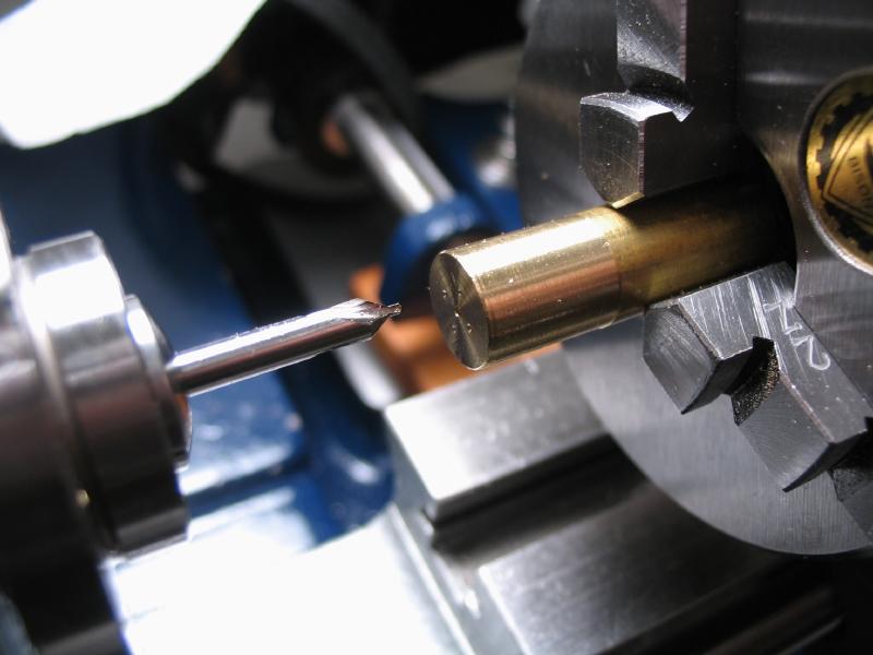
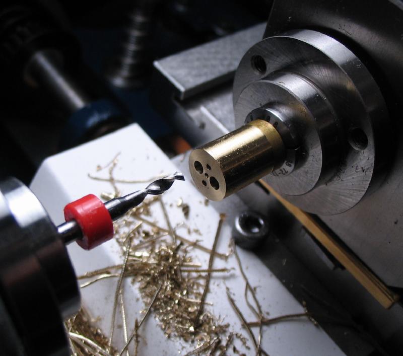
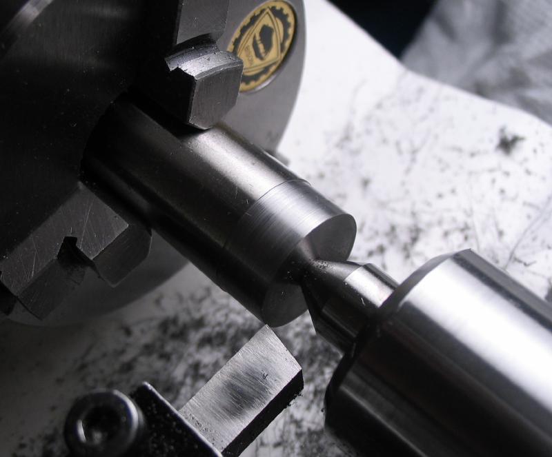
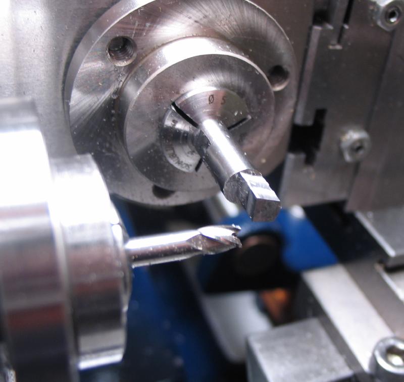
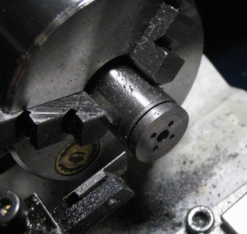
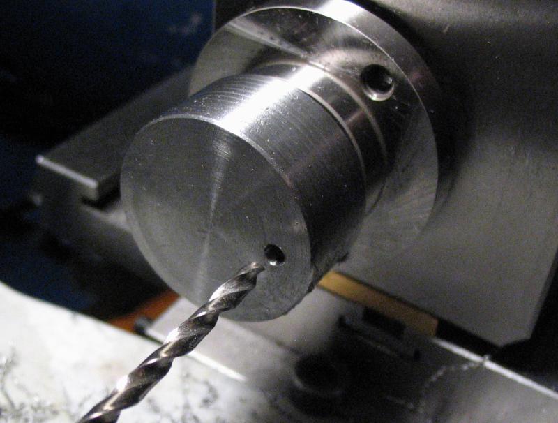
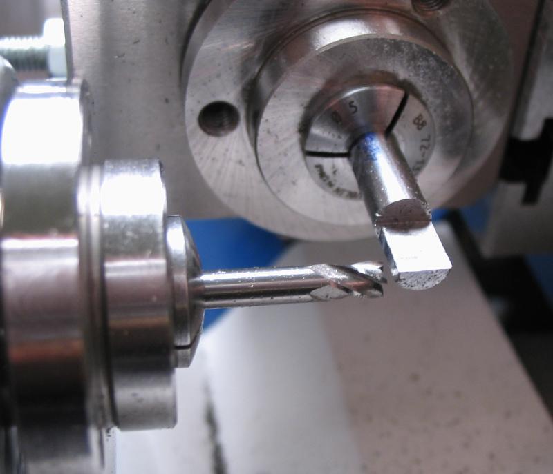
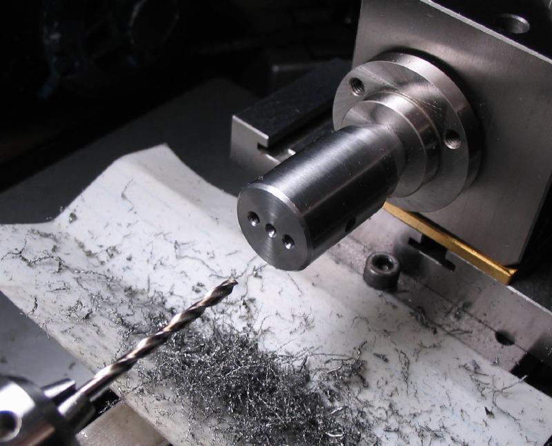
Starting with 10mm O-1 drill rod, a length is turned down to 9.5mm. The end is center drilled and drilled 1/16" to fit a pin of the same size. The end is then bored to 6.25mm diameter and to a depth of 0.5mm.
Starting with 10mm O-1 drill rod, a length is turned down to 9.5mm. The end is center drilled and drilled 1/16" to fit a pin of the same size. The end is then bored to 6.25mm diameter and to a depth of 0.5mm.
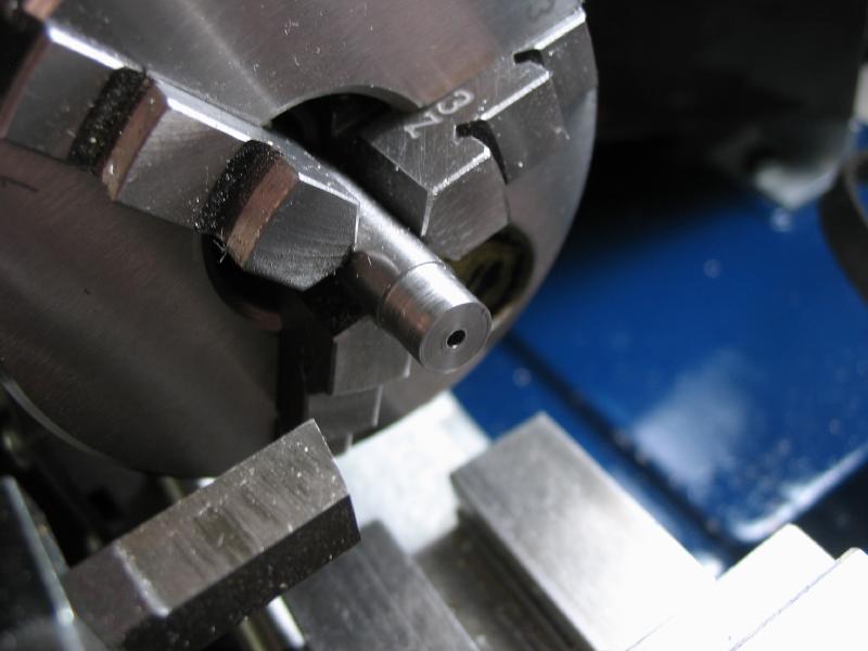
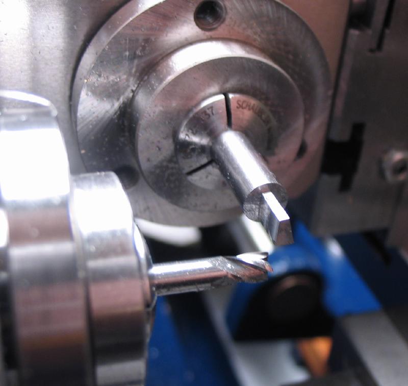
The milling spindle is setup on the lathe, and a 1" by 0.014" slotting saw mounted on a previously made saw arbor. Two, perpendicular slots are milled into the end of the steel rod. The headstock pulley is locked and indexed 90 degrees (15 holes). After the second slot is cut, the saw arbor is removed and exchanged for a collet to cross drill the rod with a 1/16" drill. This will be the locking pin hole.
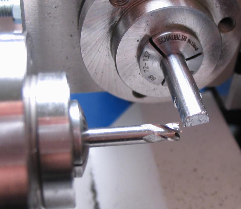
With the headstock still locked, it was cross drilled 1/16" for the alignment locking pin.
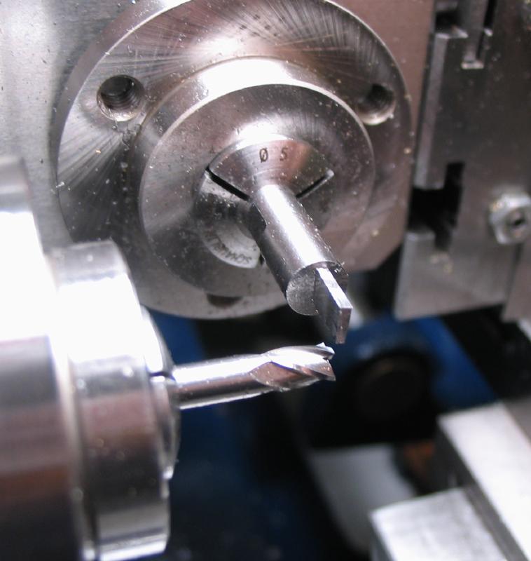
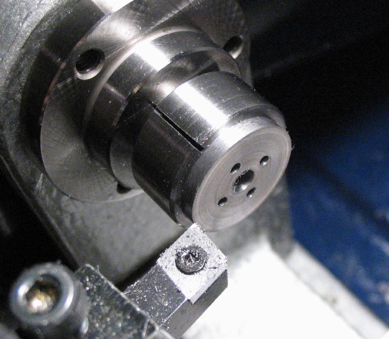
The dividing head was set up on the vertical slide and holes drilled axially through each quadrant to allow a 1mm pin to clear. This will allow the cutting punches to be tapped out after use.

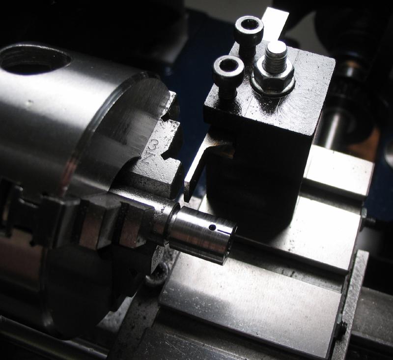
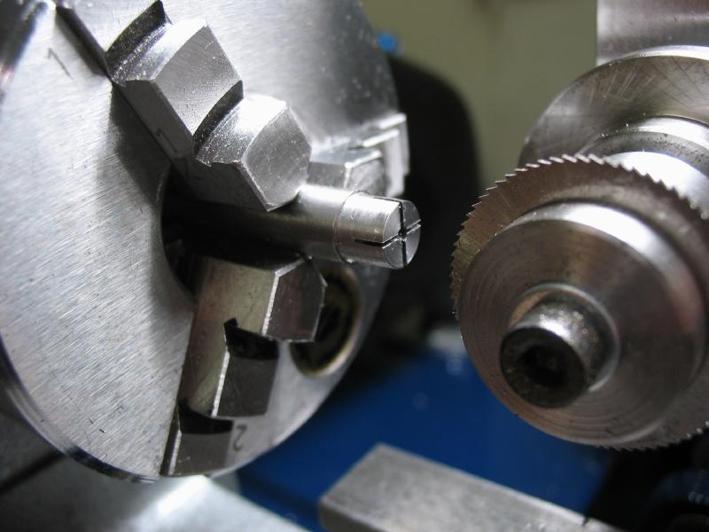
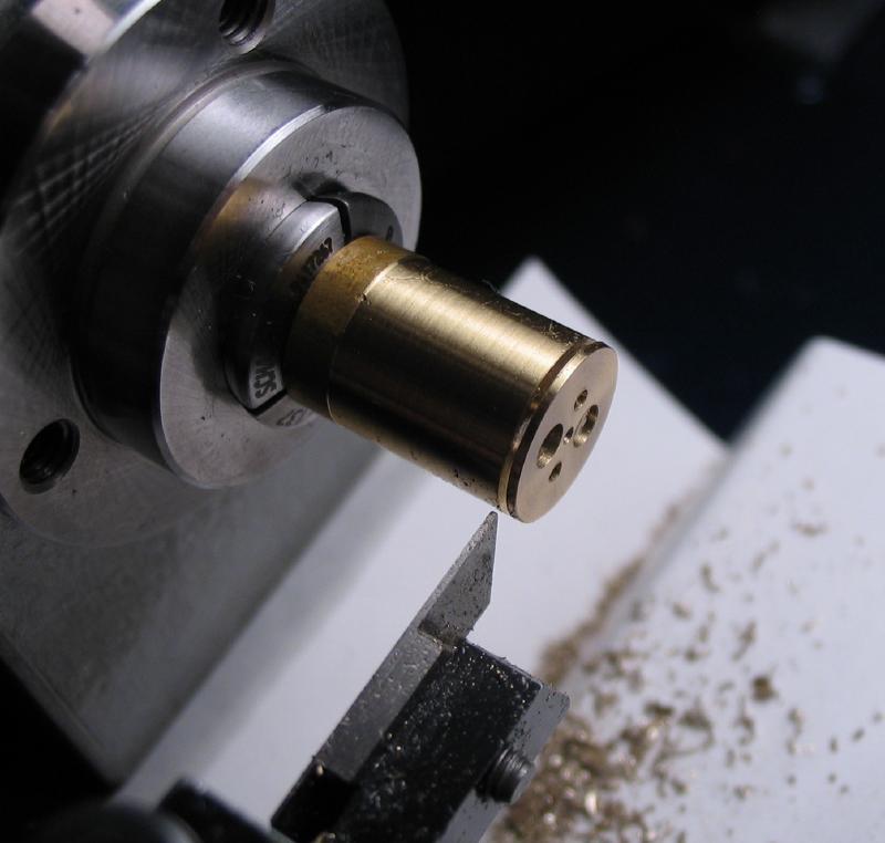
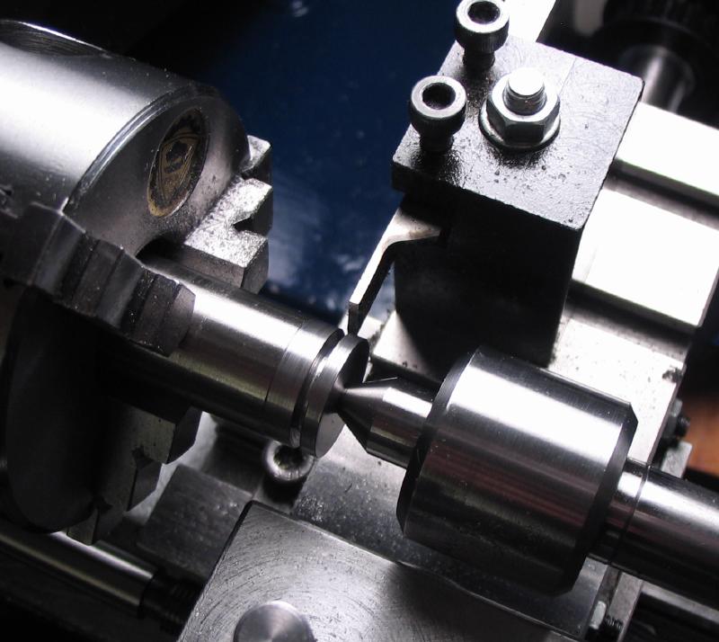
The chuck is returned to the headstock and the work can be parted off at this point.
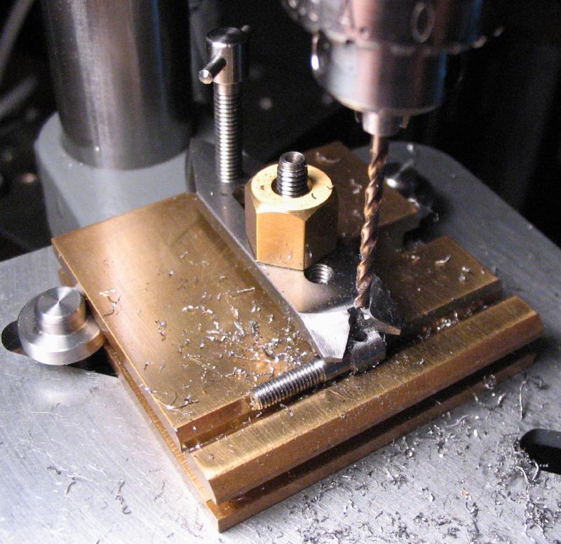
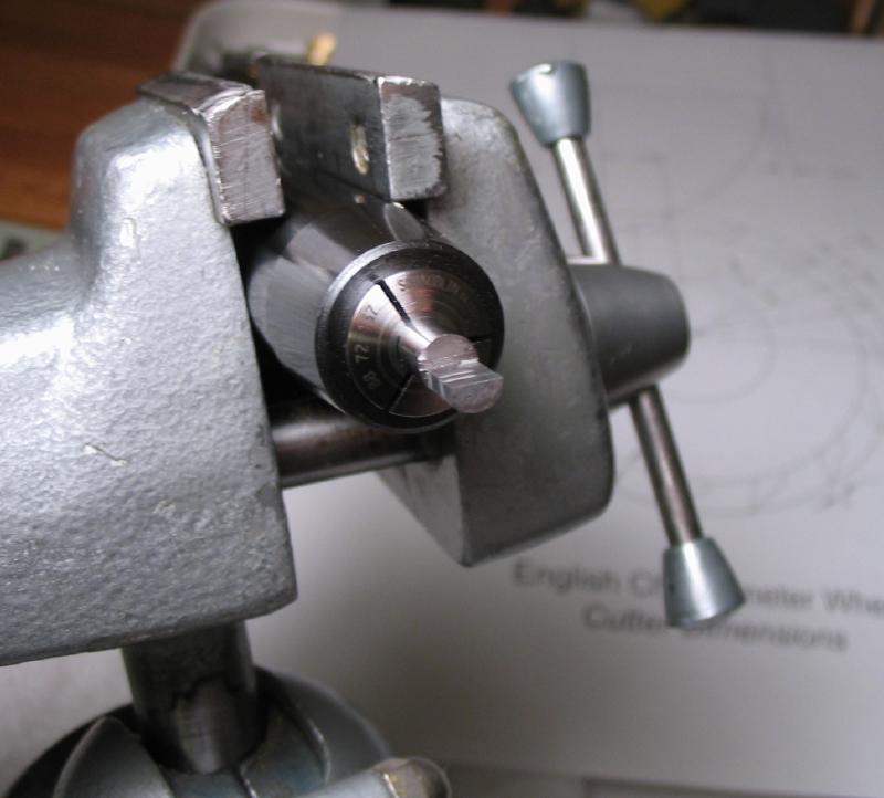
The drilling was not quite deep enough, therefore it was completed on the drill press. The work was held in the machine vice with a brass plate to receive the drill as it passes through. The depth gauge on the Cameron was useful for determining final depth.

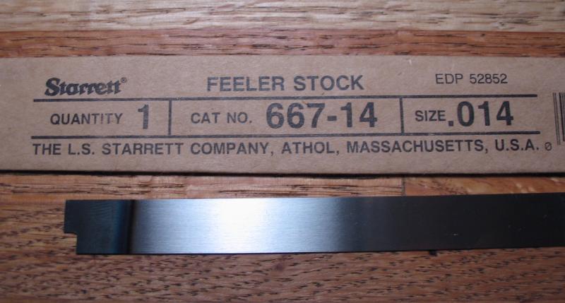
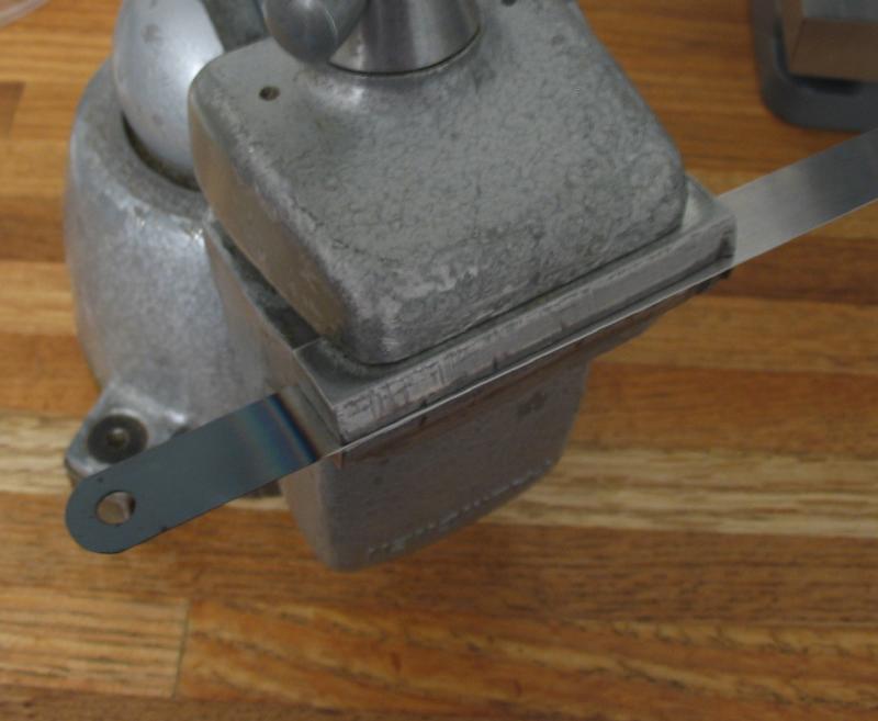
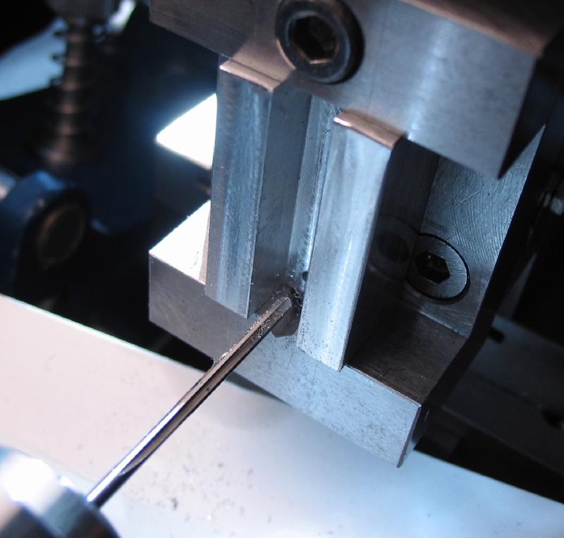
The slots are filled with steel strips. Gauge plate is not offered in this thickness, however, Starrett (and others) offer feeler gauge stock in numerous, thin sizes. It is in a spring temper, so it must be annealed. A length is held hanging out of the vice and heated to red with a butane torch, and then allowed to cool slowly.
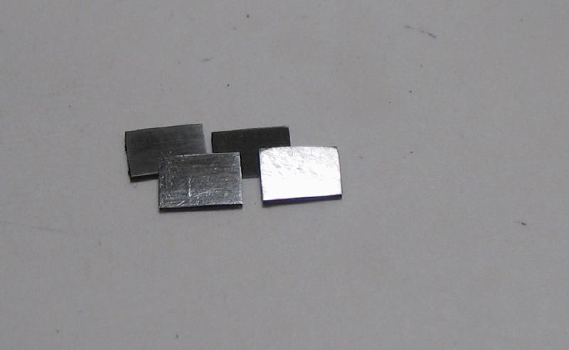
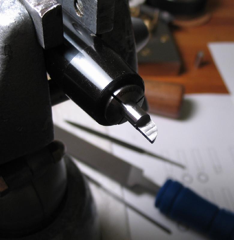
Then small squares of steel are cut out with the piecing saw and filed to fit the die.
Roughly shaped
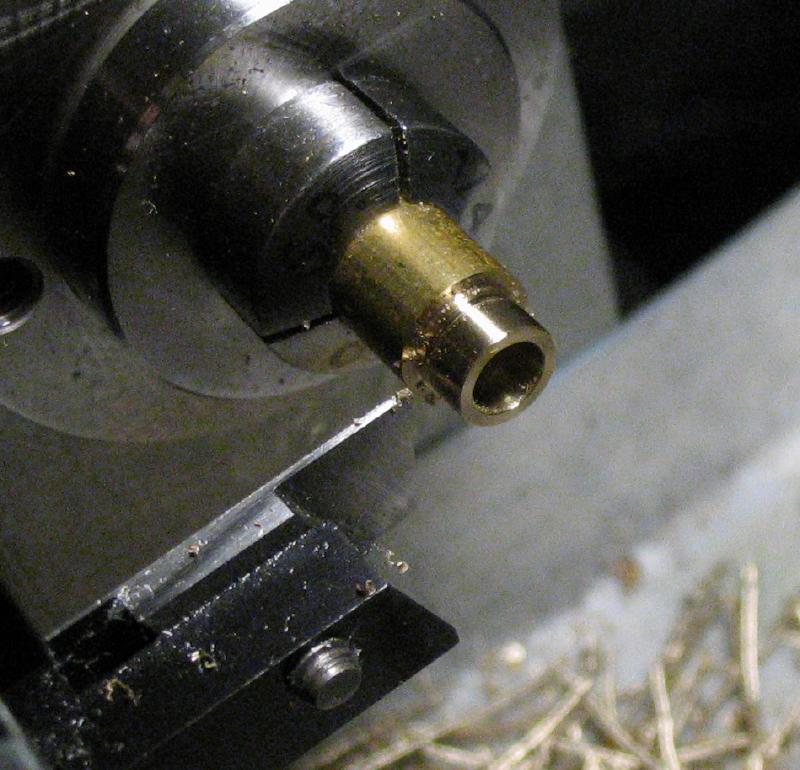
The brass guides are made from 3/4" 360 brass rod. The rod is faced and a length is turned to 18.5mm.

The rod is drilled and bored to slip-fit one of the punch dies.
The position of the guide pins can be scribed onto the face of the rod.
The milling spindle is used to drill the positions for the retaining pins.
 |
 |
The dividing head is used to drill and index the rod to for the guide pin positions.
 |
 |
One hole is drilled to pass the guide pin, the second hole is reamed to friction fit the other guide pin.
The guide is parted off using the rear toolpost.

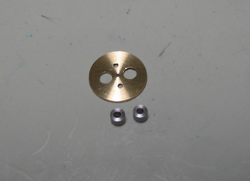
The various parts at this point.

One of the guide pins is hammered into place.
It is important that the brass guides are accurately aligned. Of course, after making the two guides separately, they do not align properly. I suspect the fault lay in drilling the holes for the guide pins. If made separately, the positions must be very accurately laid out, and very accurately centered for drilling. When making the two above, I laid the first one using a compass and 0.5mm scale. The second was scribed with a center in the lathe tool post. Both used the dividing head to find the 180 degree position.
Alternatively, I decided to remake them by machining them together and then separating them, that way the outside diameter, center bore and guide pin holes will be aligned and concentric.
The process is nearly the same, just twice the length of starting material. It requires fairly deep drilling and boring. Both guide pin holes were drilled 2.5mm. After separating opposing holes need to be enlarged to 3.0mm.


Punches
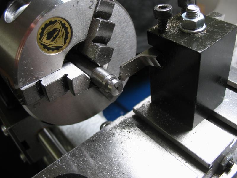
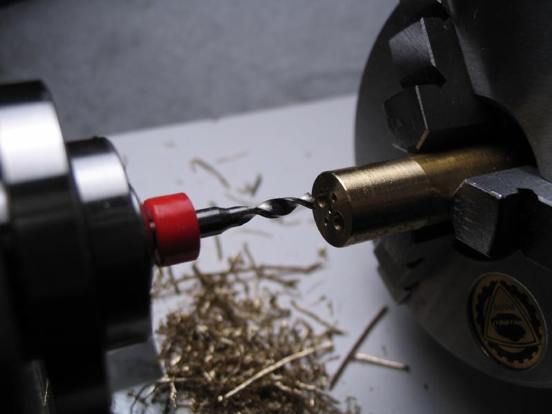
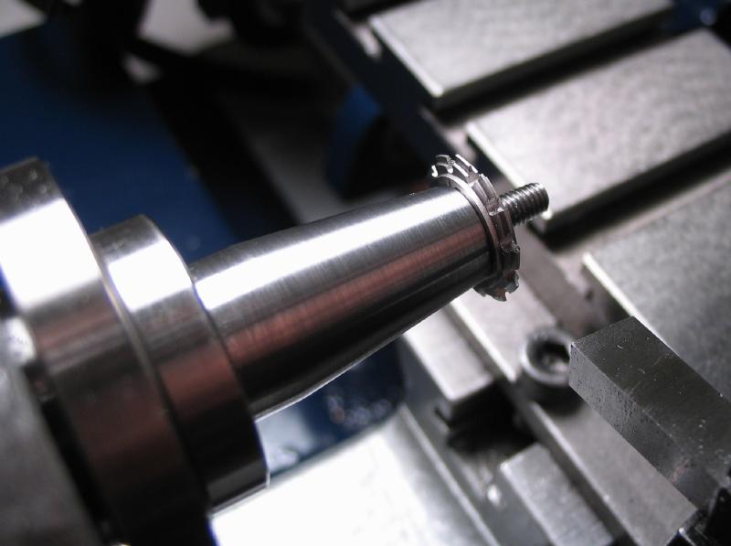
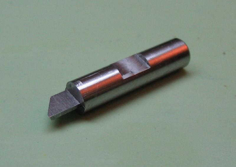
The actual punches that cut through the blank can be made to fit the dies. A piece of 7mm of O-1 drill rod was turned to ~6.25mm with a slight taper (~1 degree). The taper will help prevent the tool biinding when in use. The rod is drilled 1/16" to match the hub diameter of the wheel.
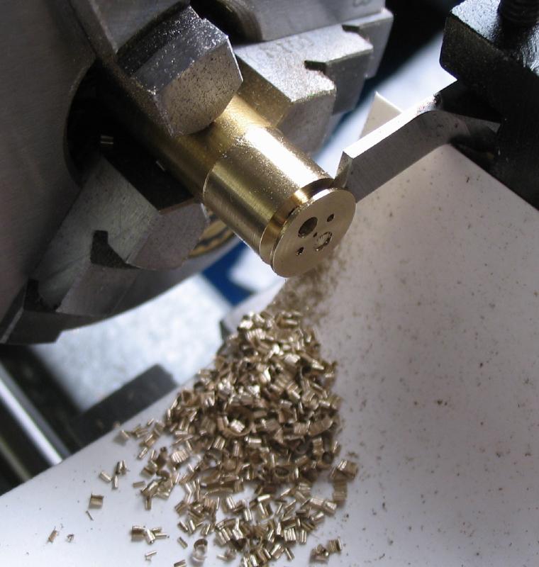
Then the rod is slotted with a 0.014" saw, perpendicular cuts are made using the headstock to index.
The punches can then be parted off.
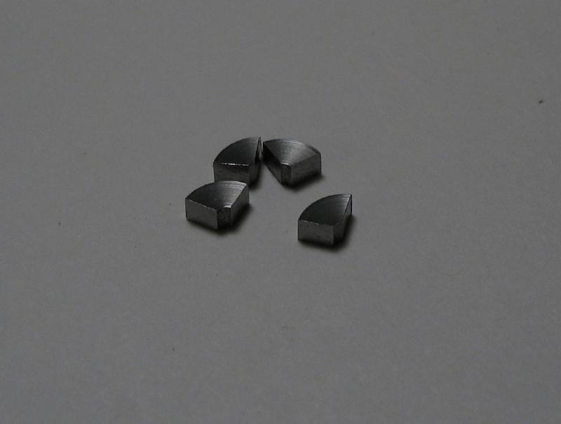
I remade the punches several times, in the last run I parted them off the stock using a slotting saw rather than a parting tool. This gave a much cleaner cut.
The steel components can now be hardened in oil and tempered to a straw color.
Version 2
The stamping die above works fairly well, however, the spokes of the resulting wheel blank are somewhat deformed from the cutting pressure. Alternatively a series of two stamping dies are constructed below in which the first stamp roughly cuts out the blank with under-sized spoke spaces and then a finishing stamp brings the blank to final dimensions. The design of the stamp is same as above, but with respective changes to the dimensions of the dies and cutting bits.
First, a new frame was made since the previous was not quite ideal and received a good deal of abuse in the many experimental trials...
Faced and turned true
|
Drilled and bored to 9.5mm
|

Moved to dividing head
drilled for alignment pins
|
Reamed 2 & 3mm
|
Drilled for locking pin
|
Reamed 1/16"
|
Parted 10mm in length
|
Glue chuck faced and grooved
|
Faced side attached and parted side faced true
|
Finished frame reamed through 1/16" to assure alignment
|
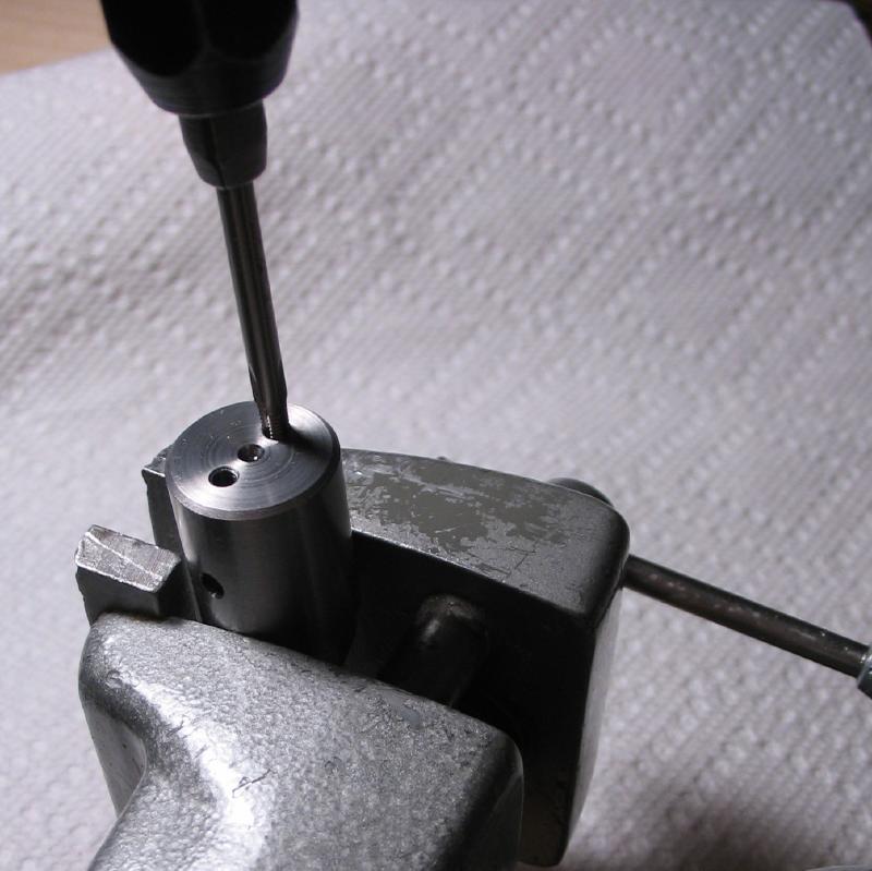
Unfortunately the locking pin holes were not in alignment. I am not certain where the error occurred, but was repeated with both pairs of frames. This was corrected by fitting alignment pins as in use, and mounted in the machine vise for drilling and reaming new locking pin holes.

|

|
|
|
|
|

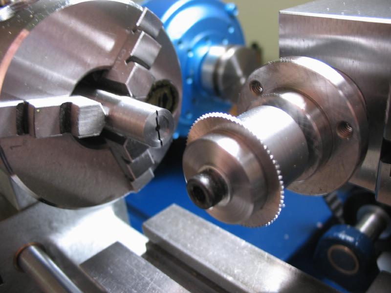
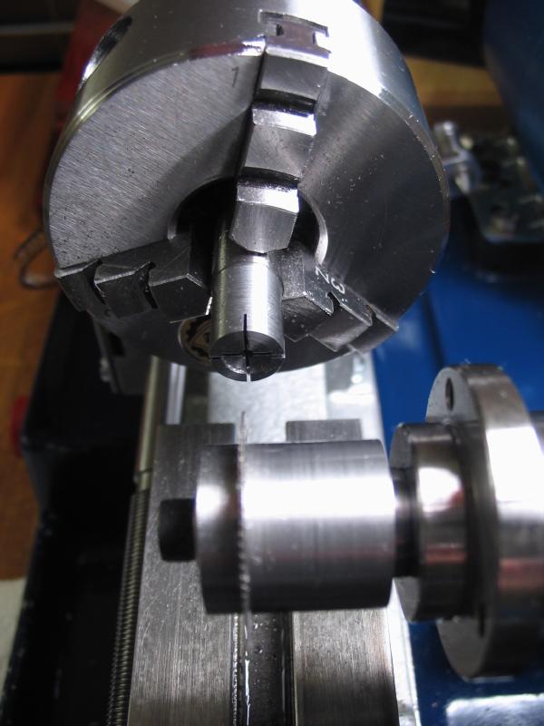
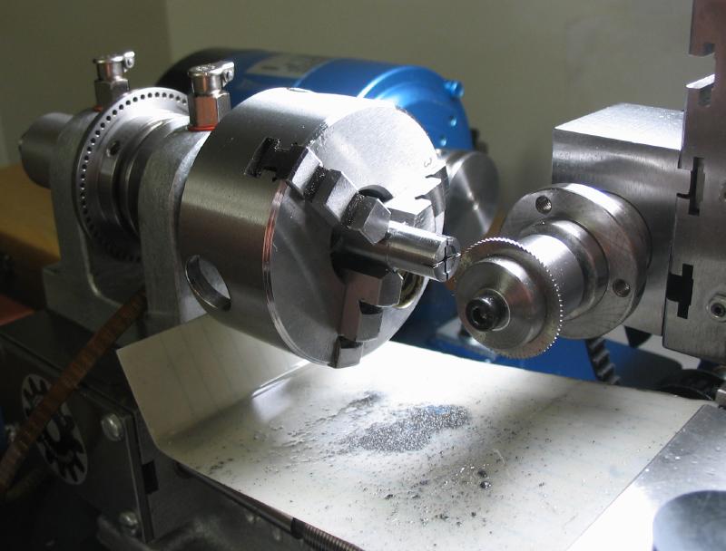
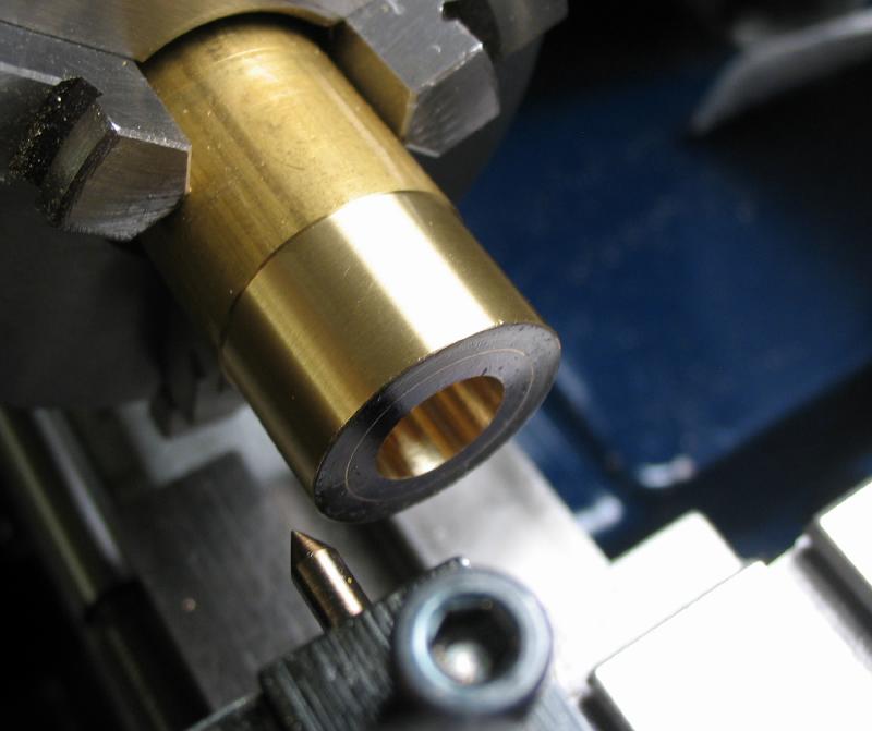
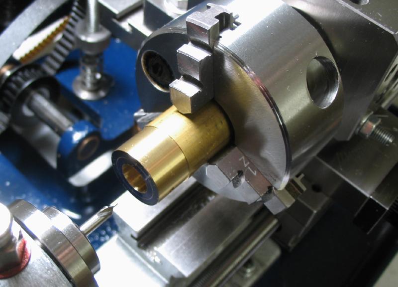
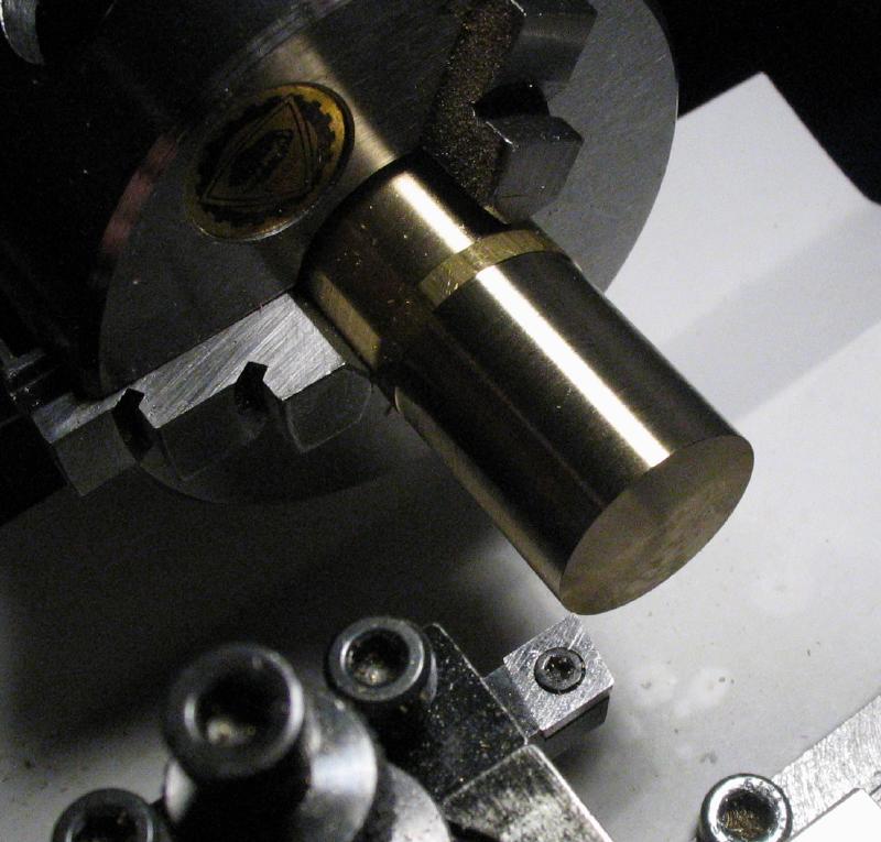
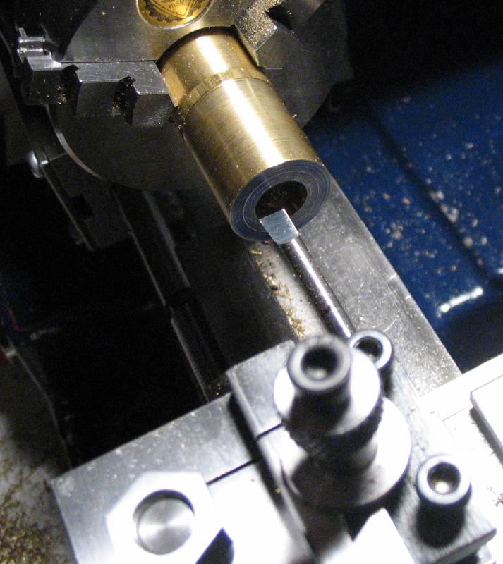
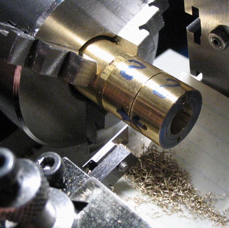
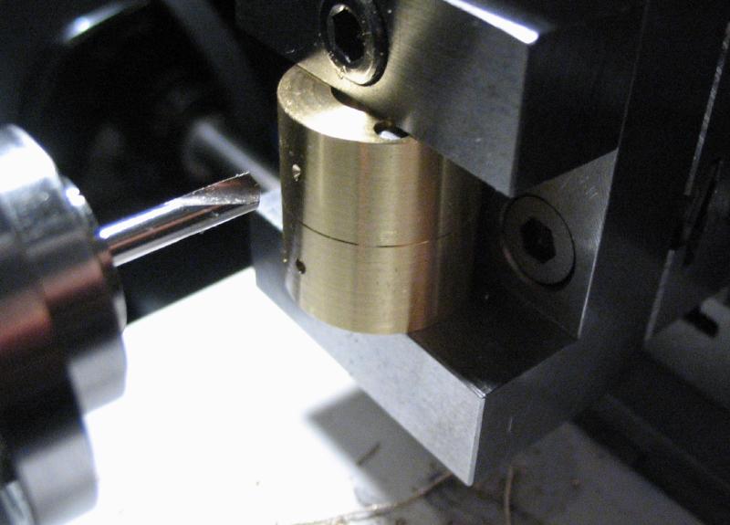
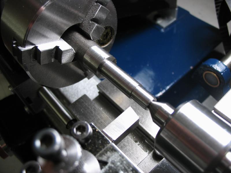
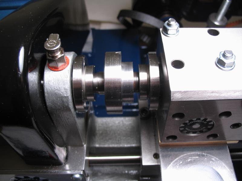
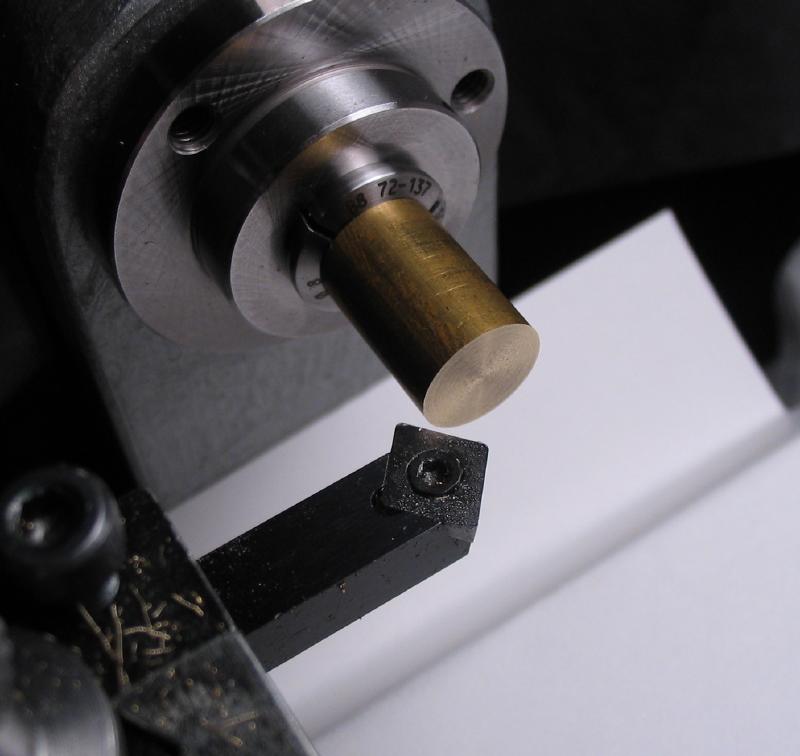
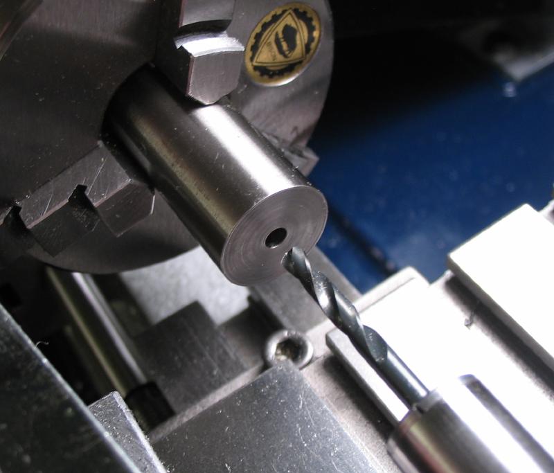
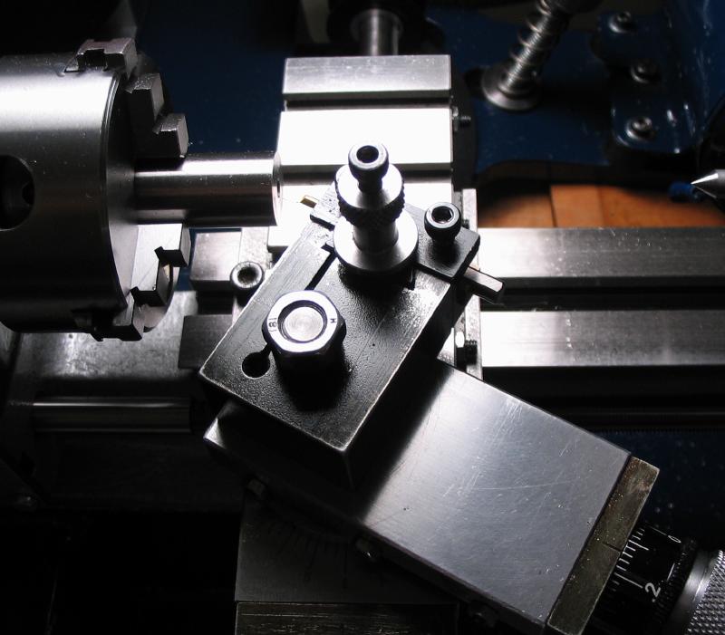
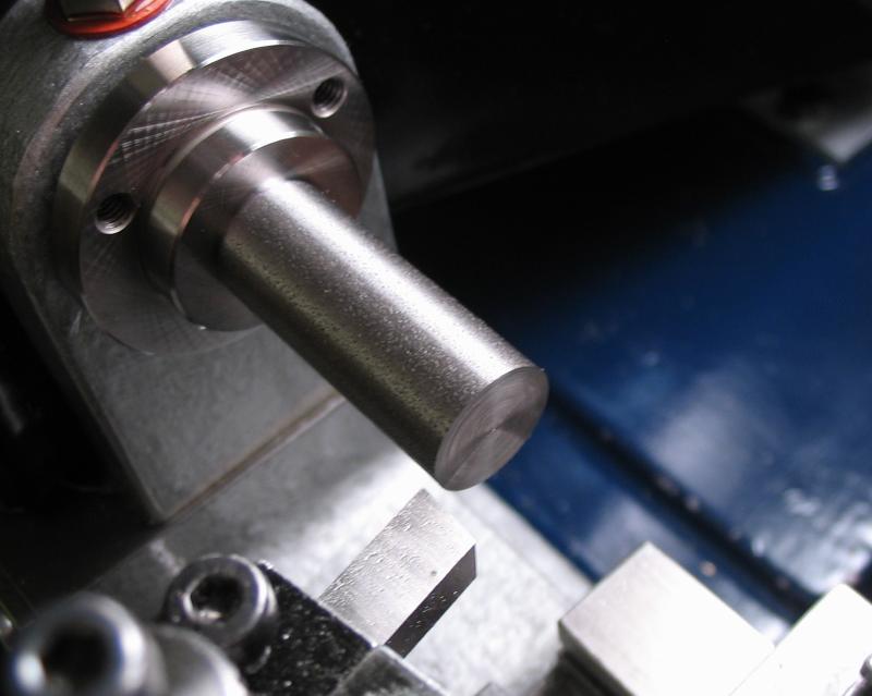
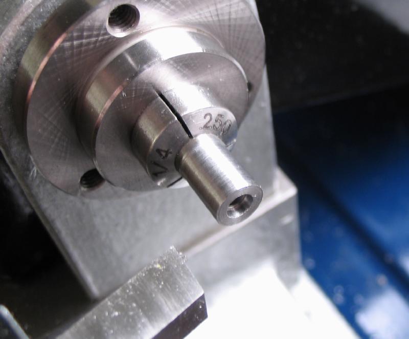
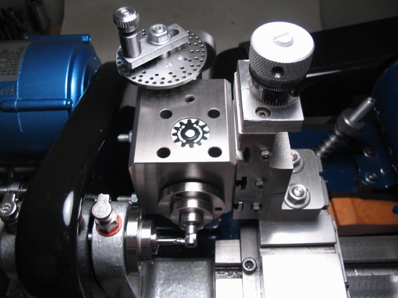
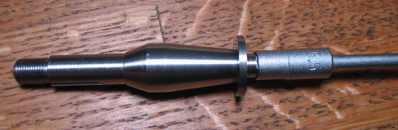
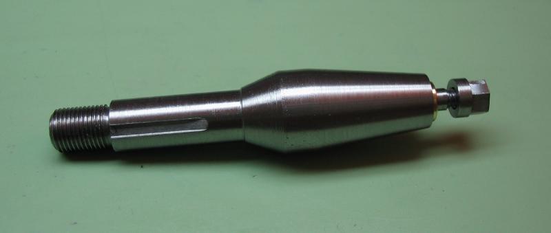
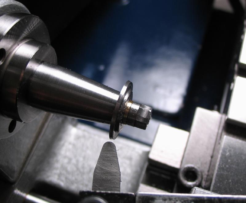
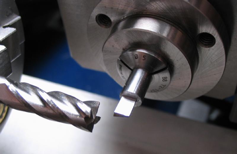
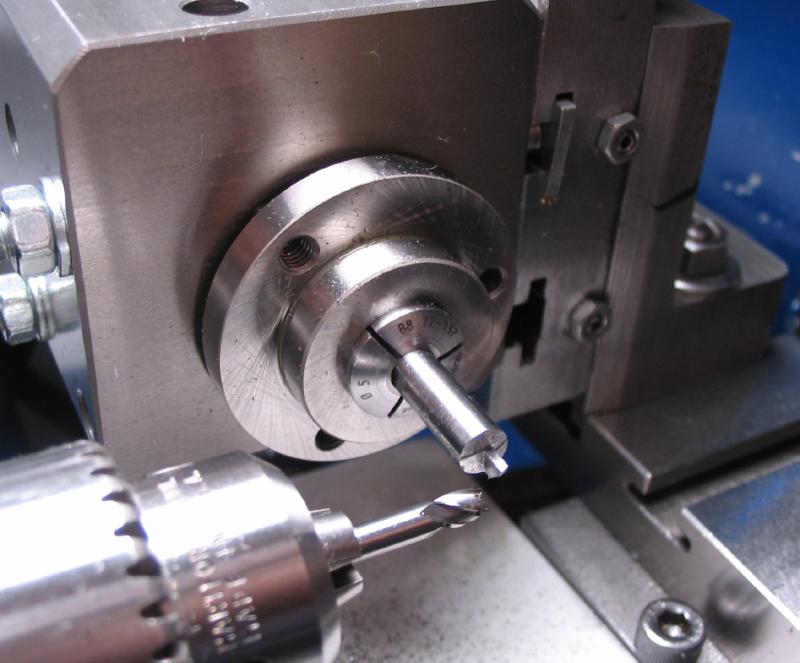
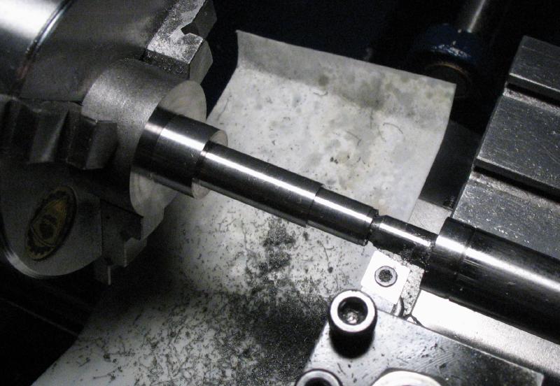
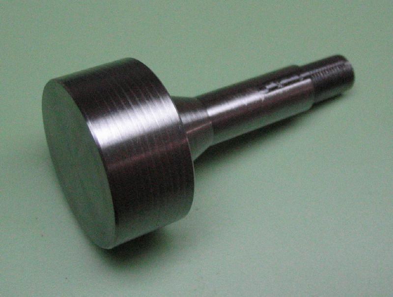
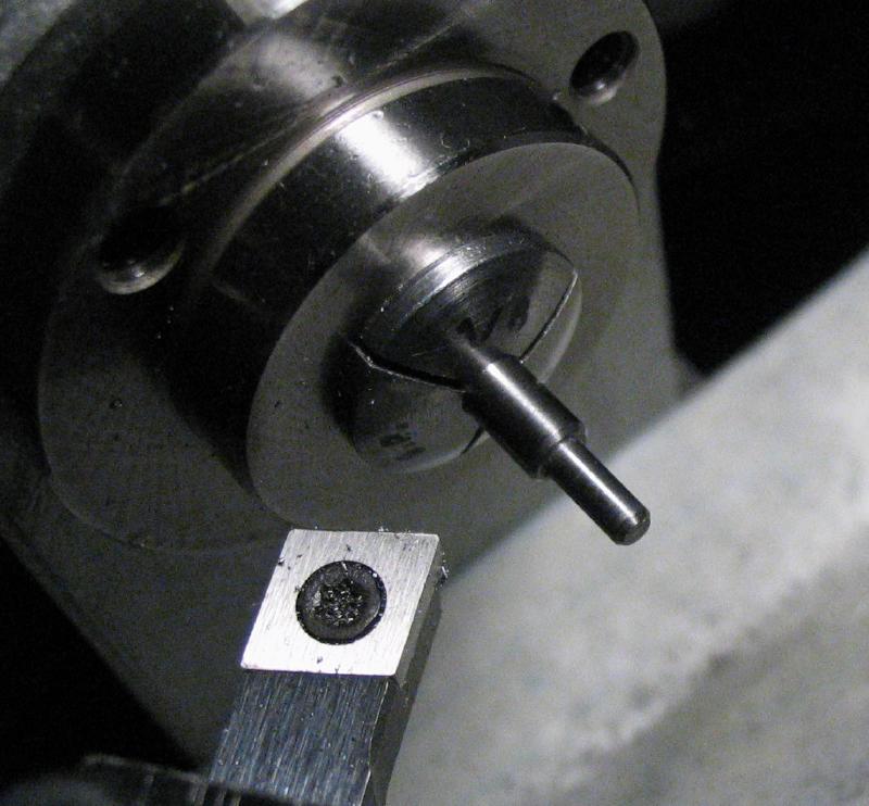
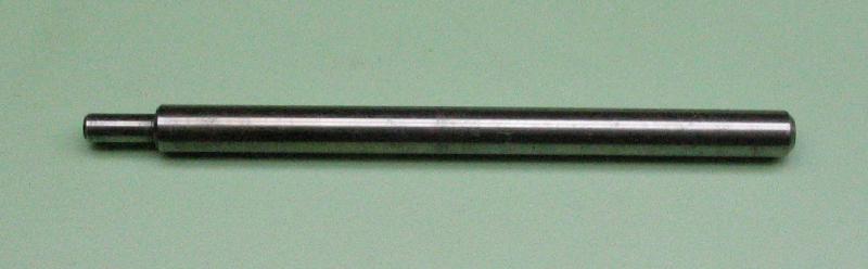
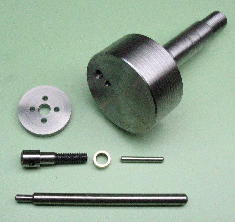
Wheel blank work-holding arbor
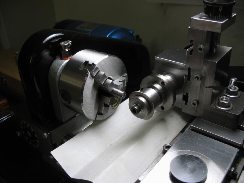
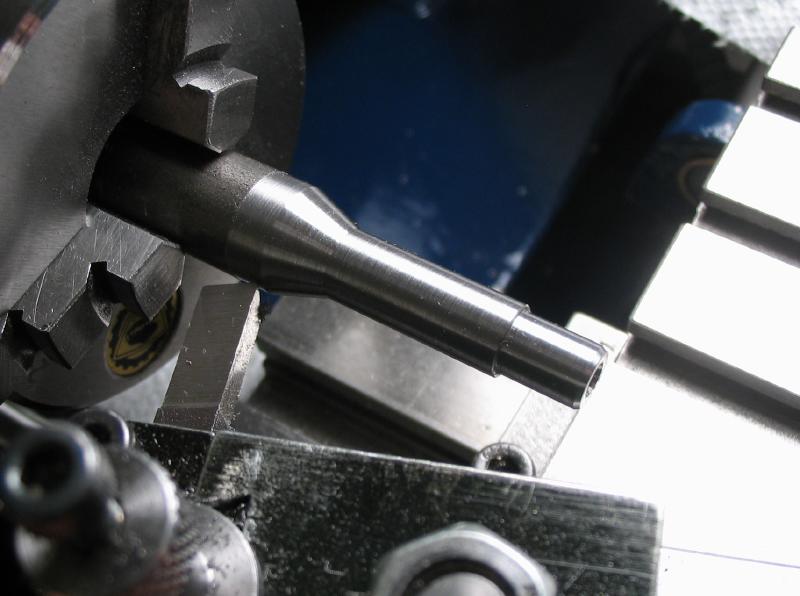
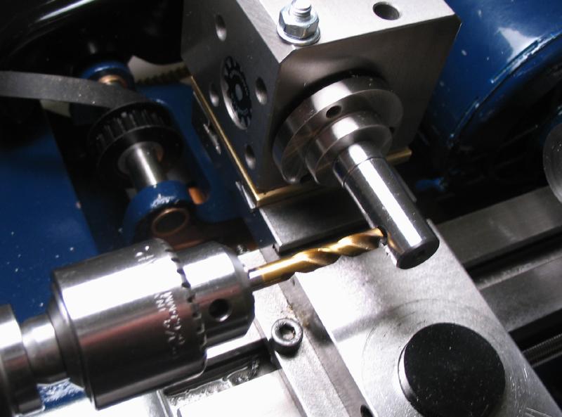
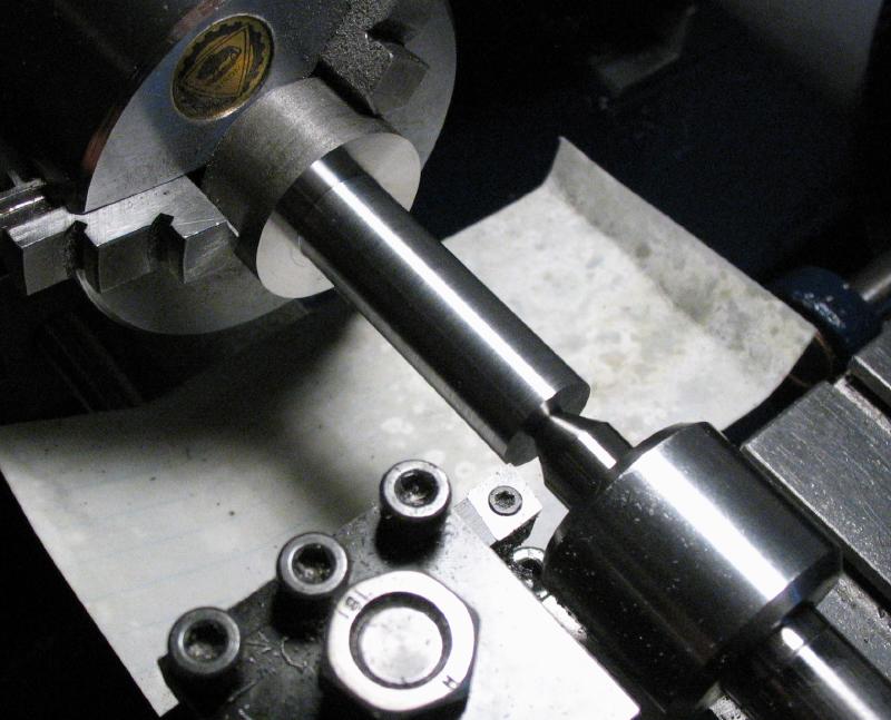
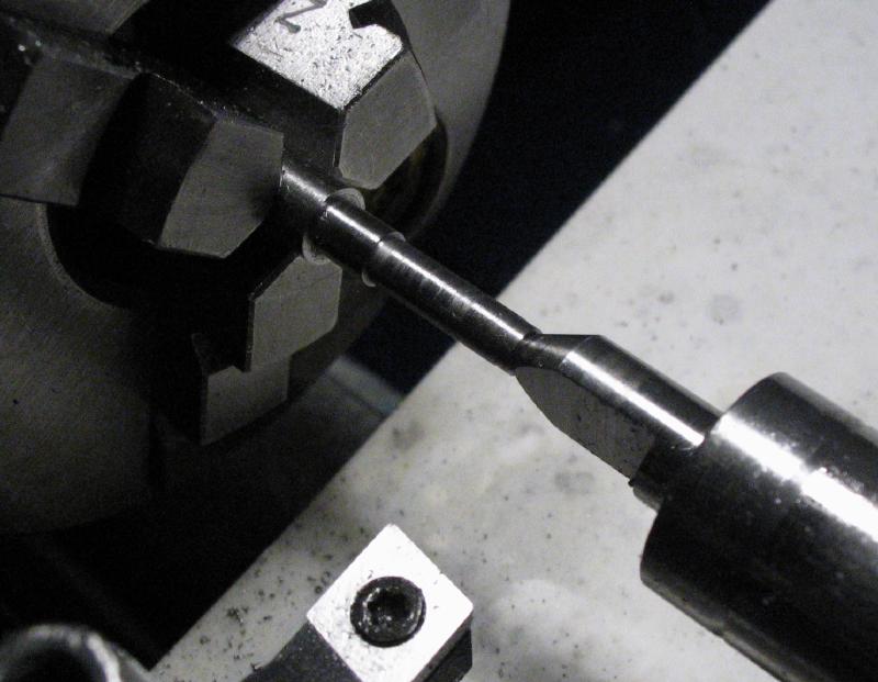
The punched wheel blanks will require a custom arbor for holding on the lathe during milling the teeth. This was started from 1/2" steel rod (12L14). It was mounted in the 3-jaw chuck and the steady rest was used to face and center drill the rod on both ends.
The dimensions needed for a collet shank are turned. Another collet was used as a guide.
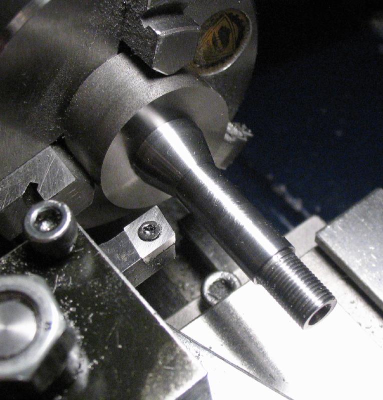
The 20 degree taper is turned using the compound slide.
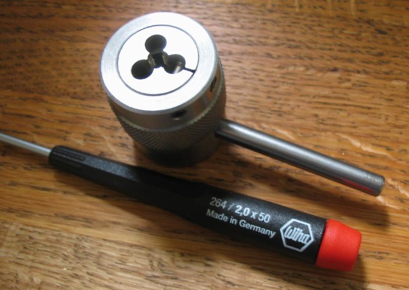
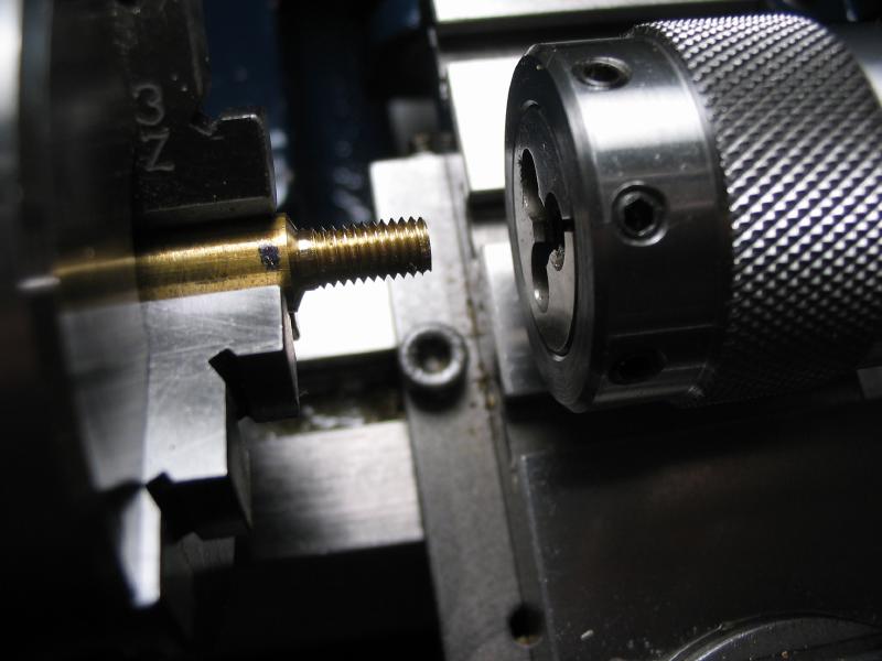
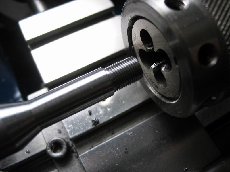
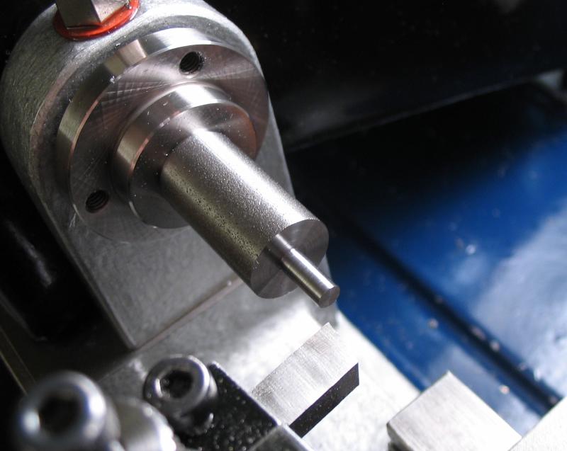
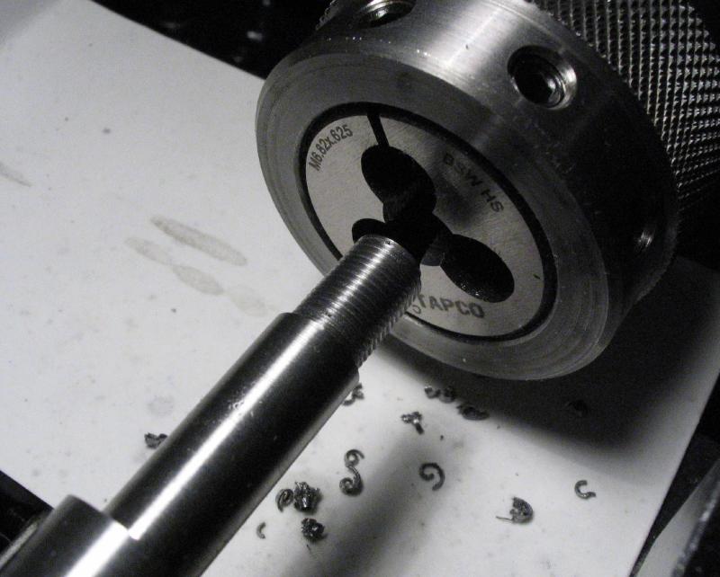
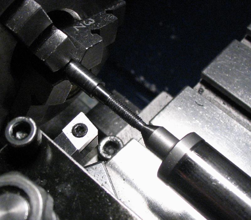
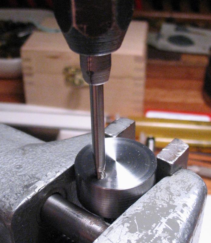
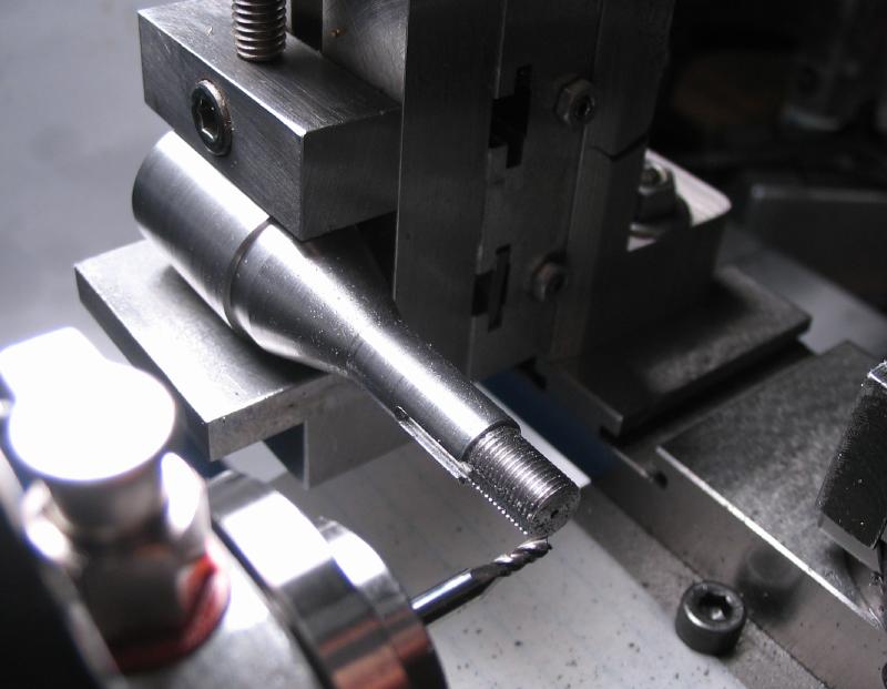
Threaded with the tailstock die holder and a B8 die.
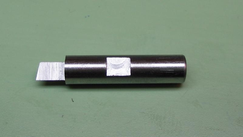
The 2mm keyway is milled into the shank using the milling spindle.
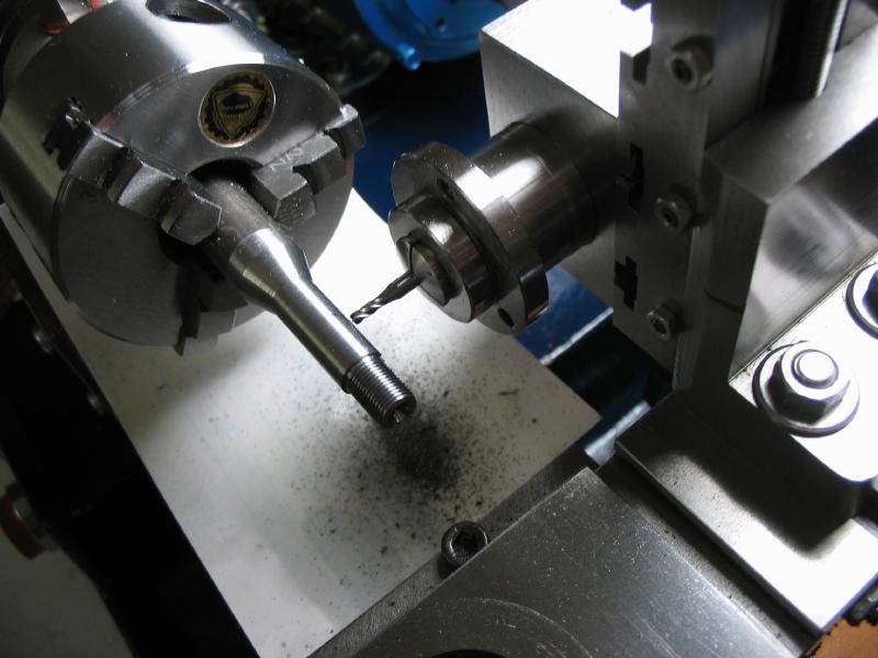
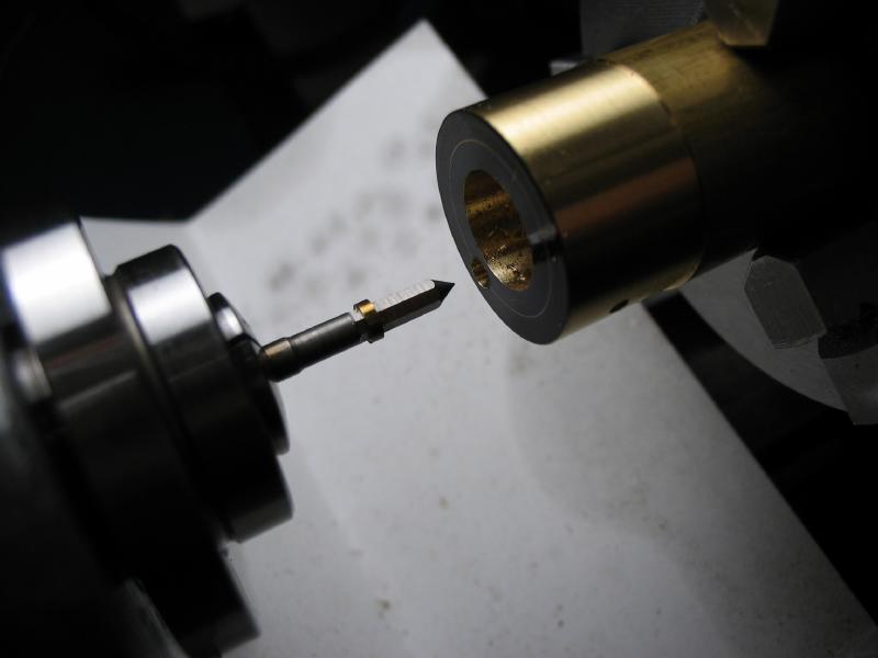
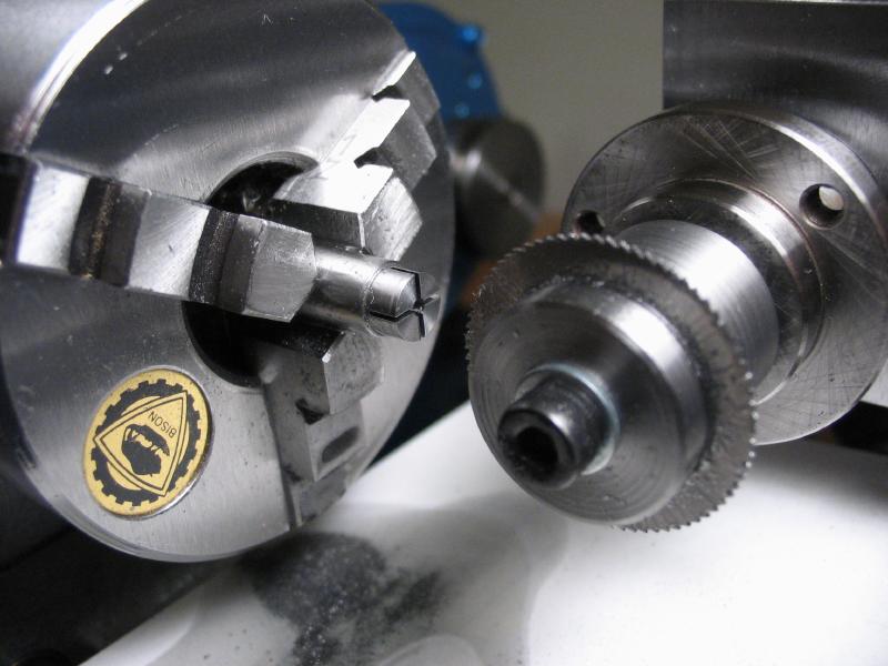
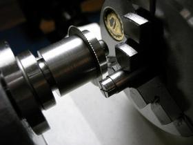
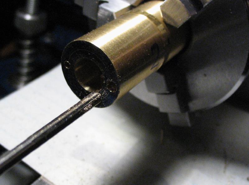
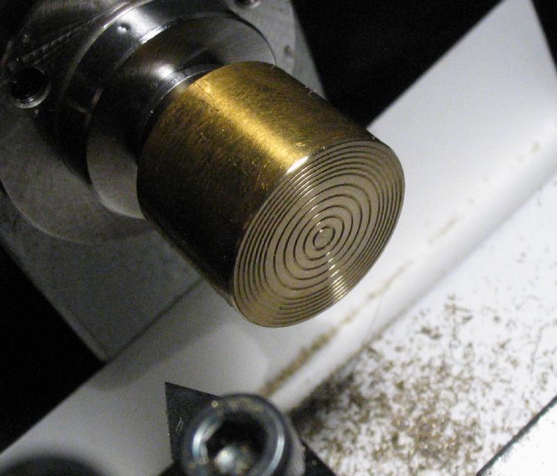
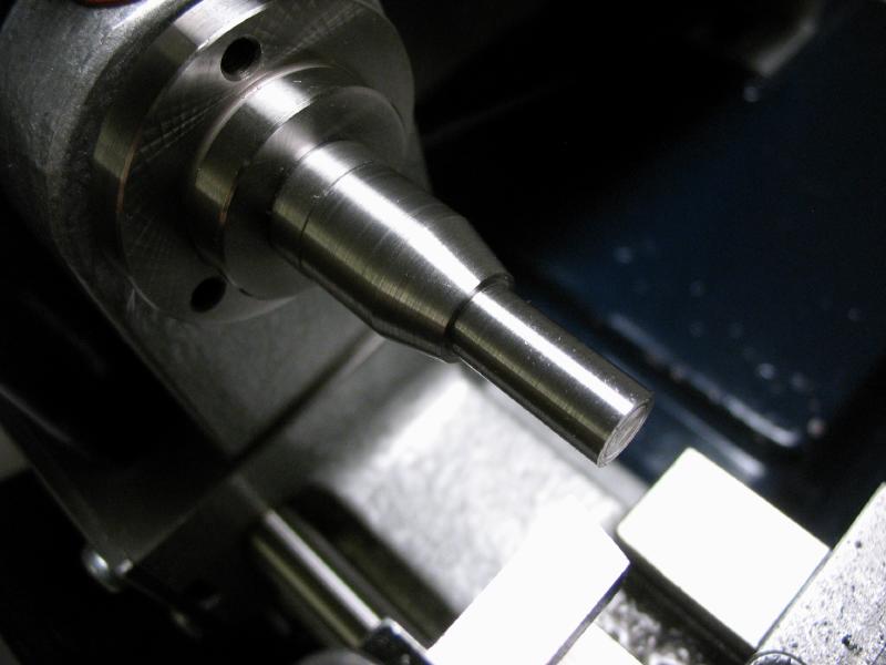
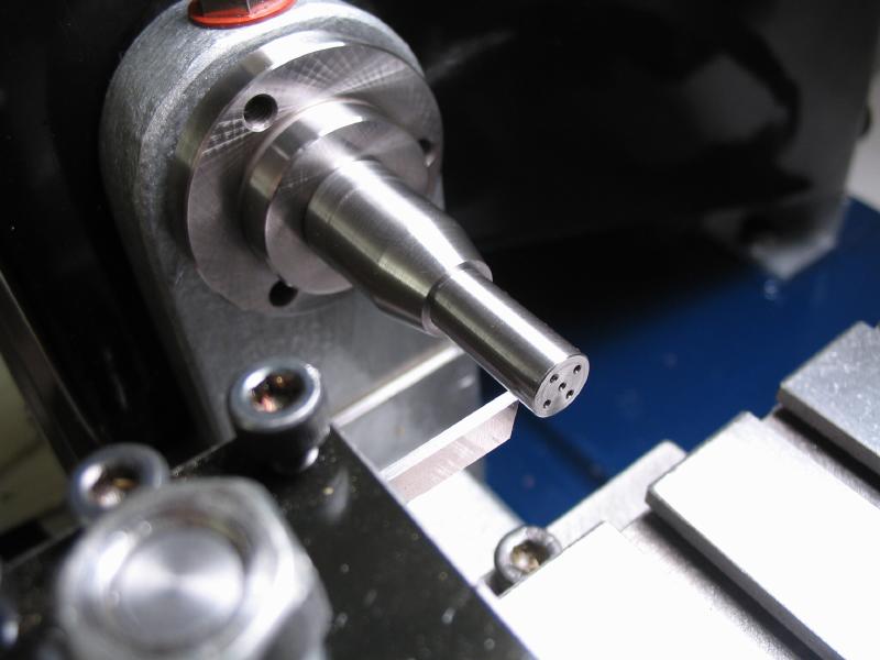
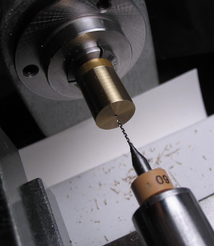
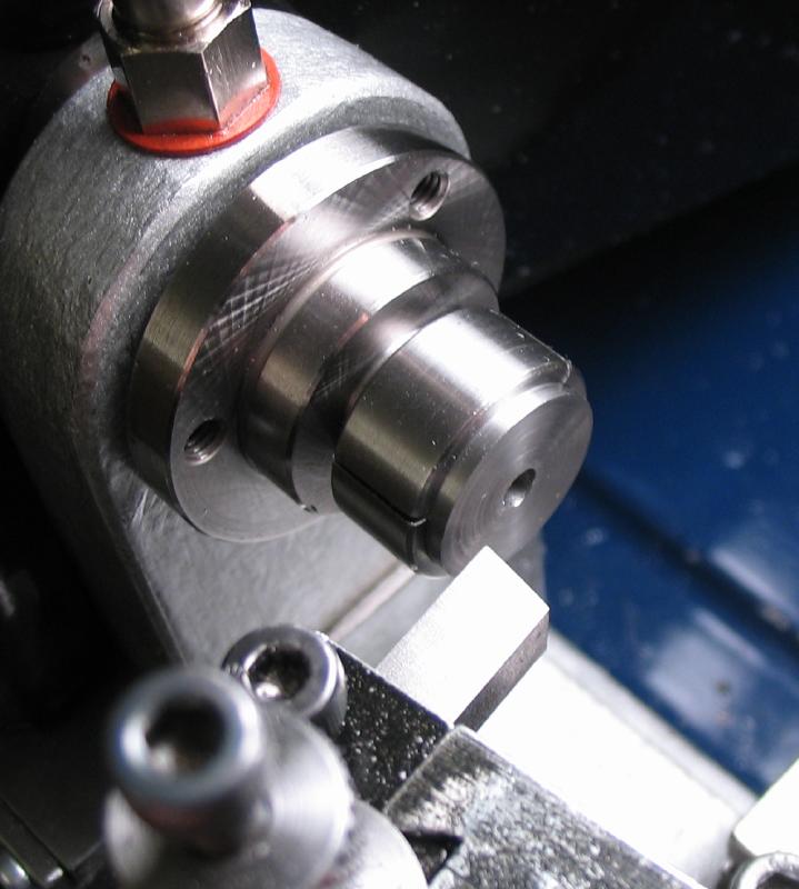
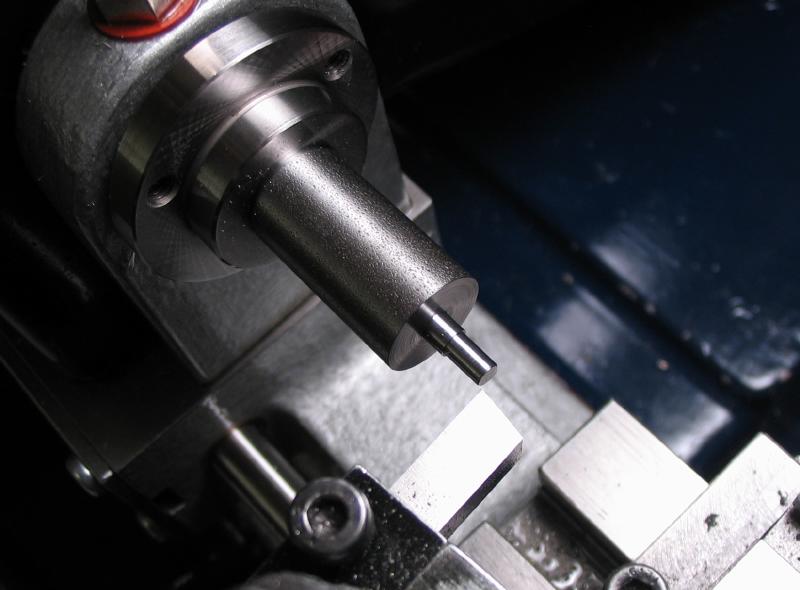
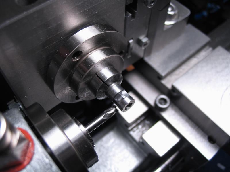
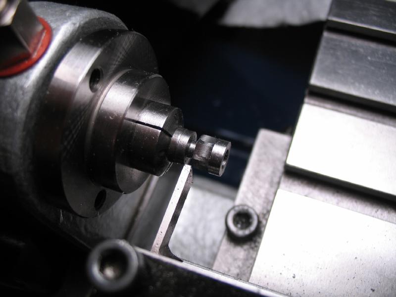
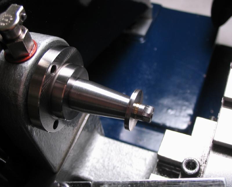
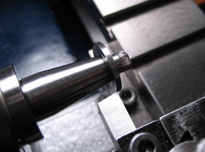
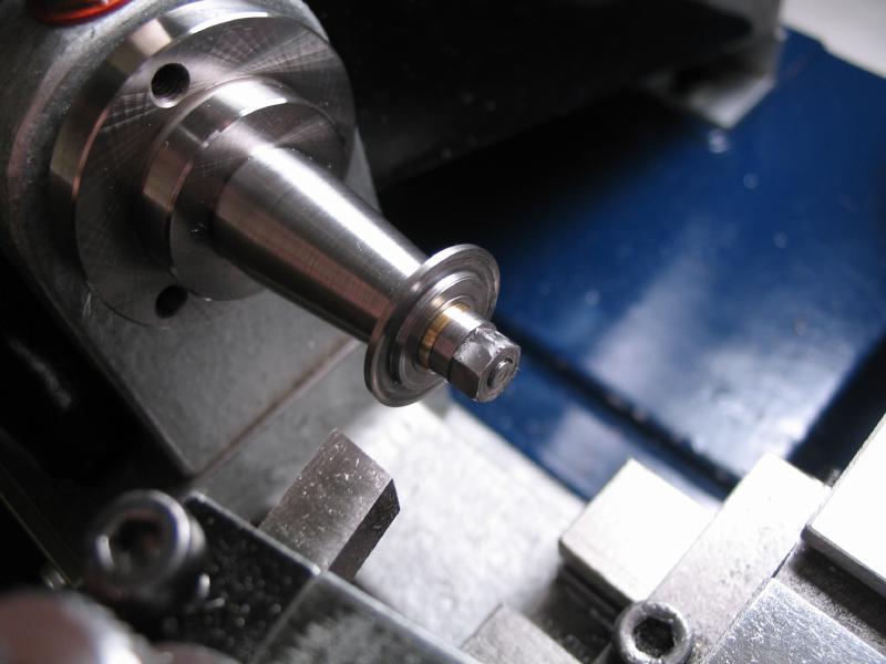
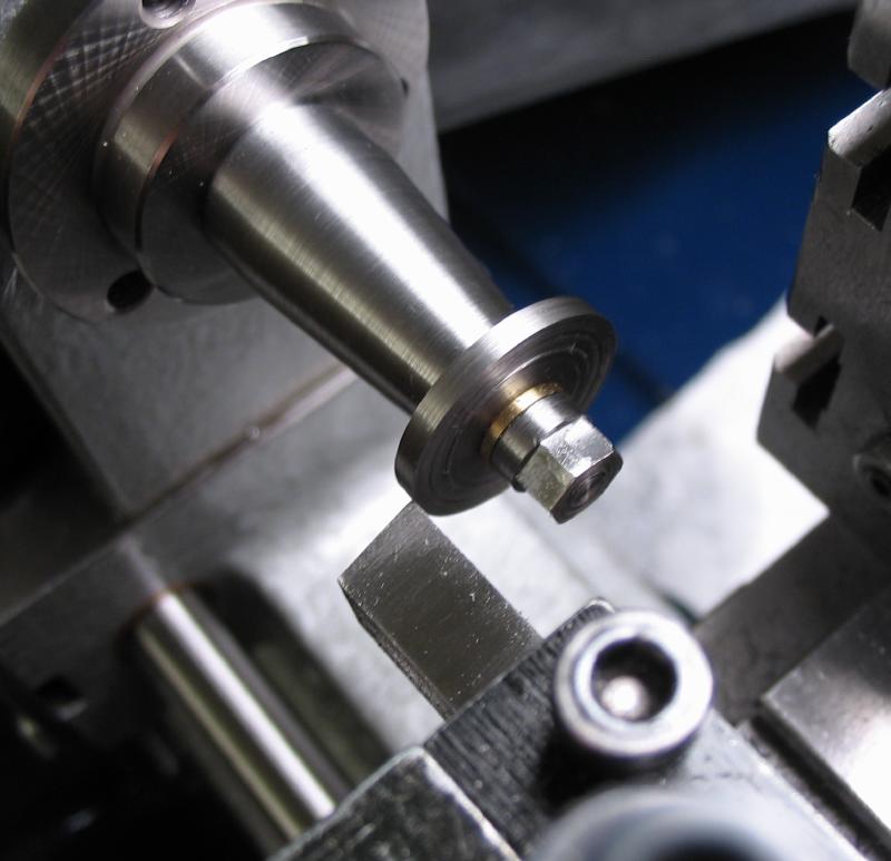
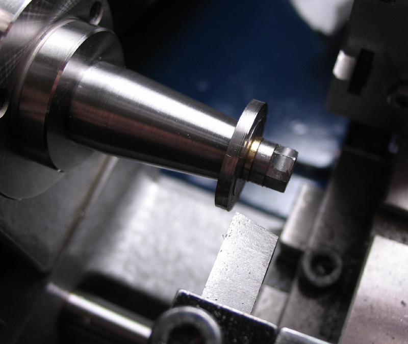
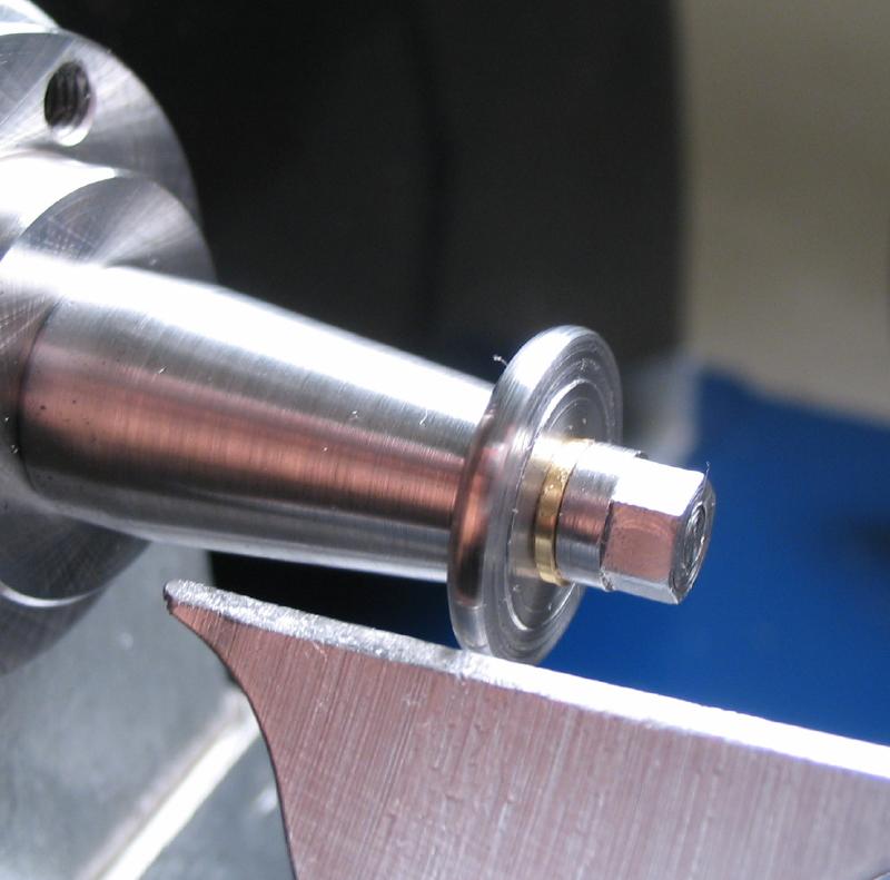
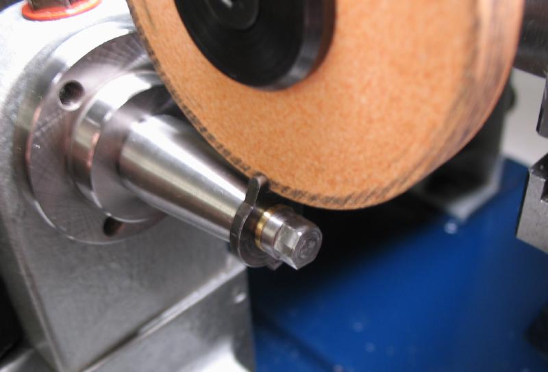
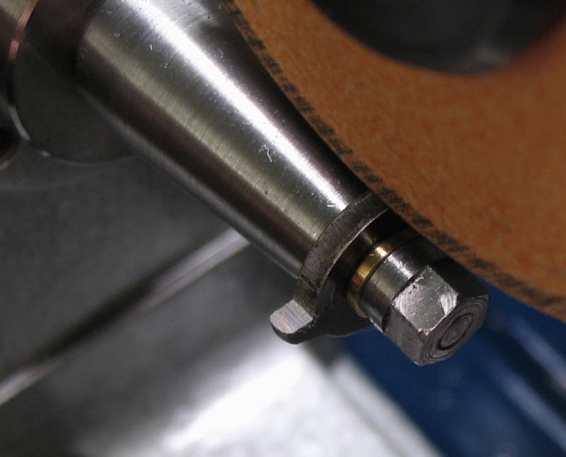
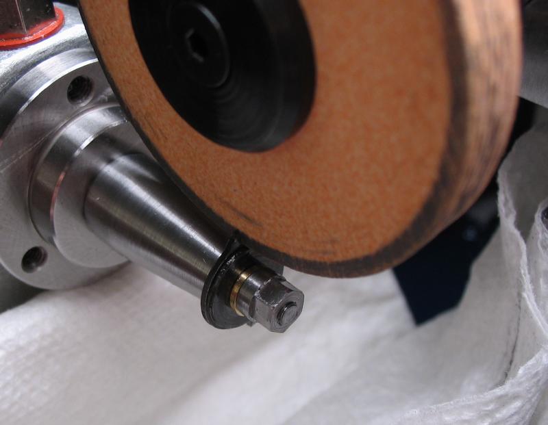
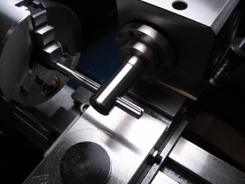
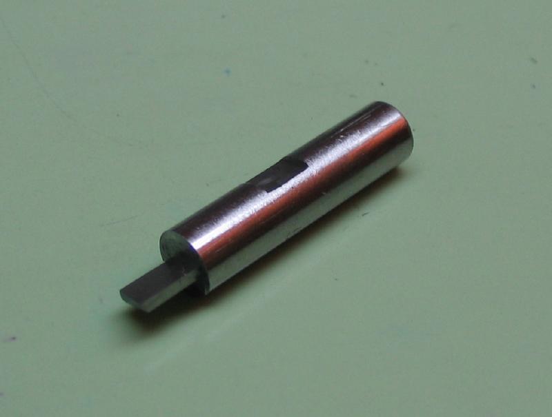
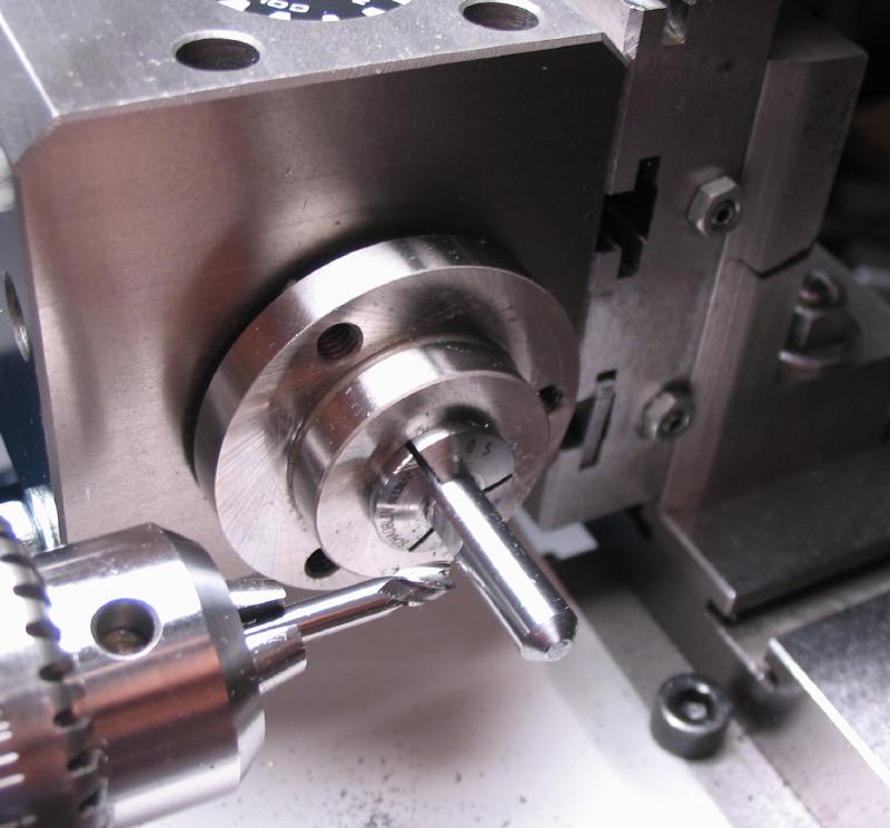
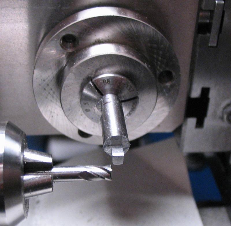
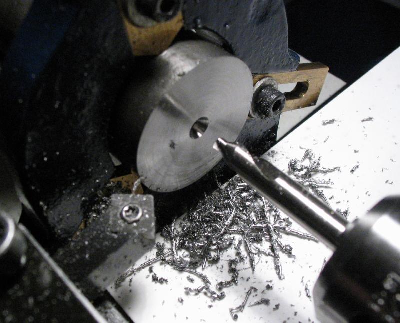
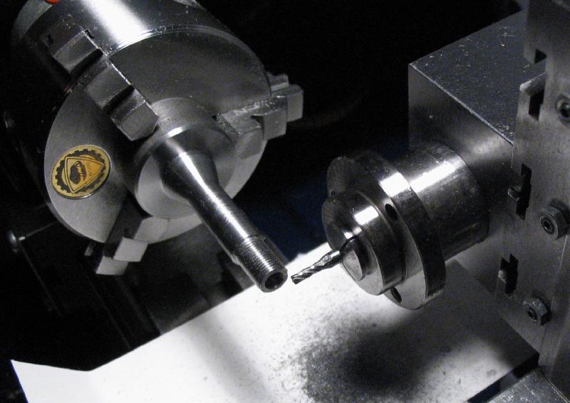
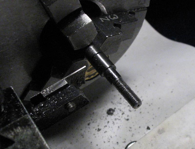
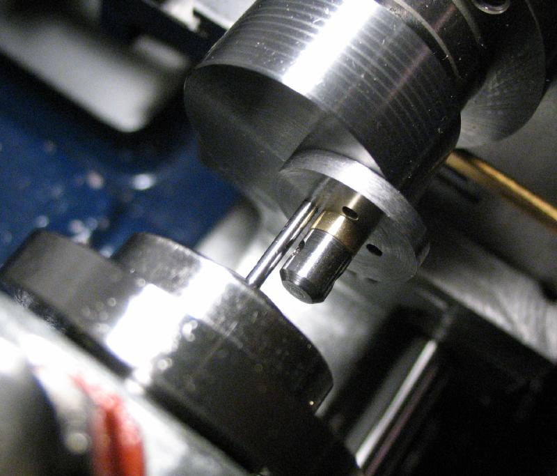
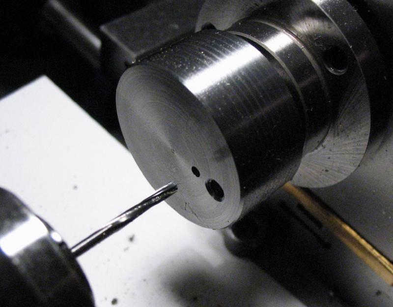
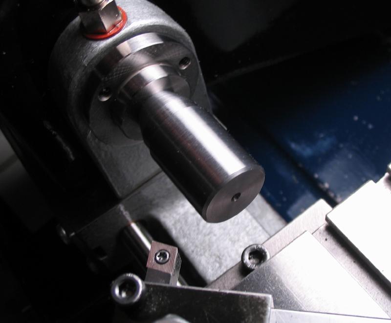
The arbor can then be mounted in the headstock using the drawbar. The business end can be turned. The tooth depth was determined to be 6.9mm, so the arbor was turned 6.85mm. It was then drilled 0.55mm to accept a center pin that the wheel blanks will center on.
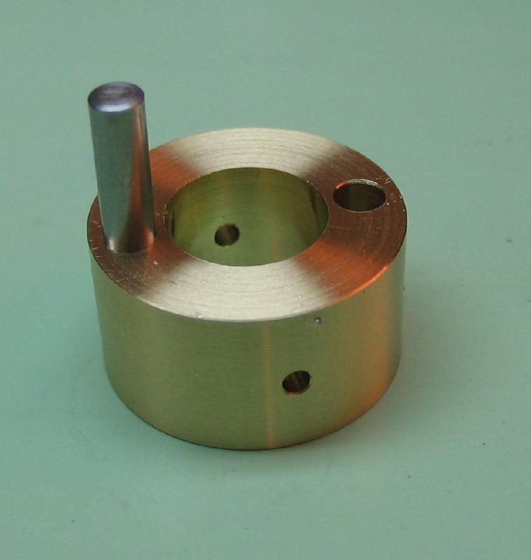
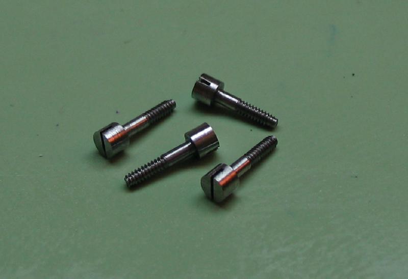
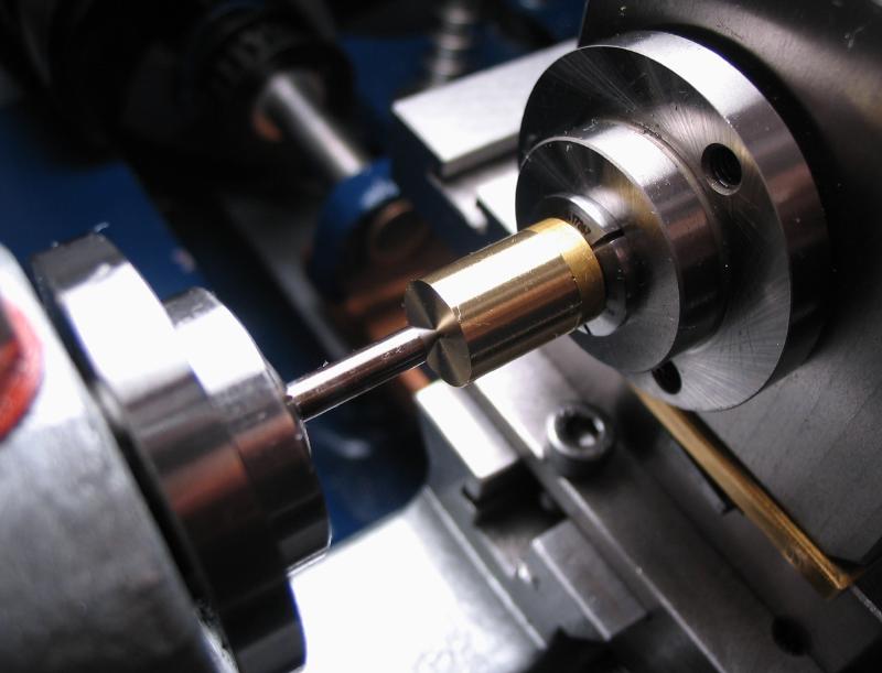
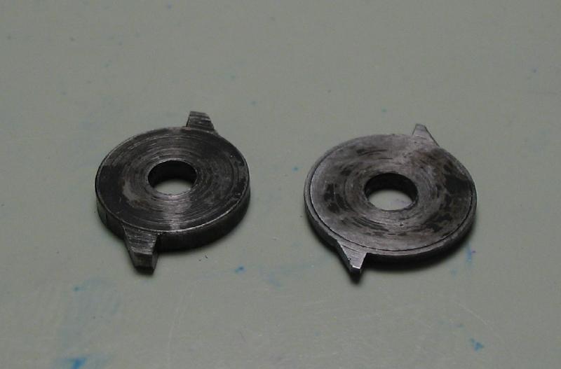
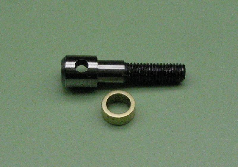
The retaining washer and wheel blanks are held in place by four screws. I made a batch of shoulder screws with 1.0mm threads and 2mm heads. They are hardened and tempered blue.
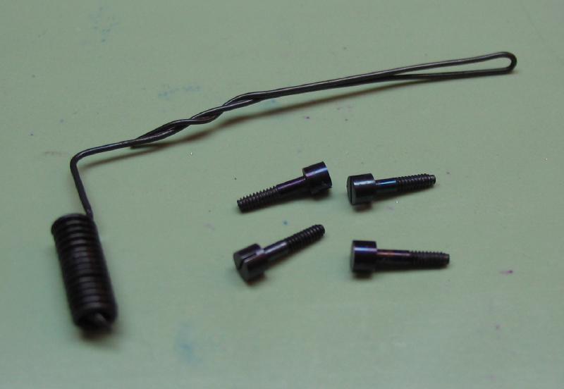
Blued screws and the hardening basket made from iron wire
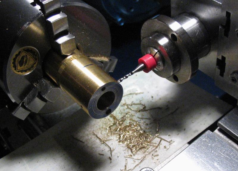
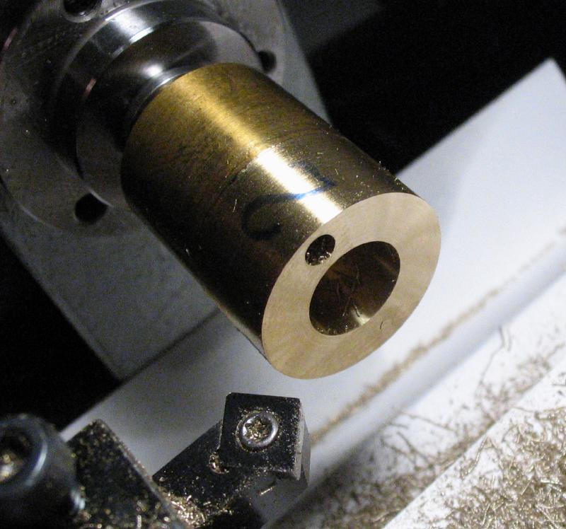
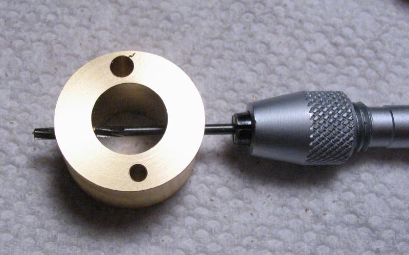
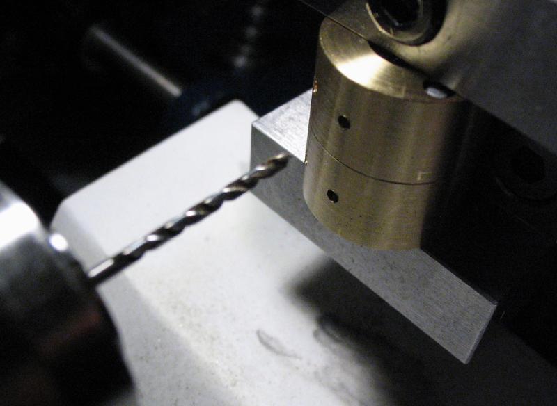
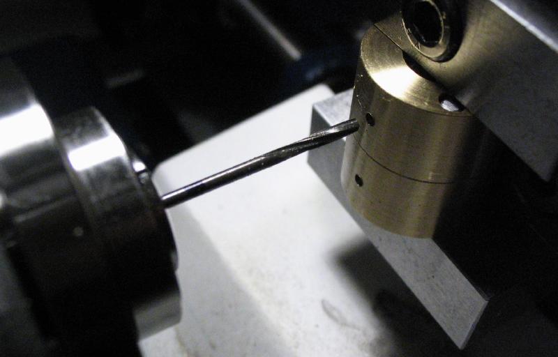
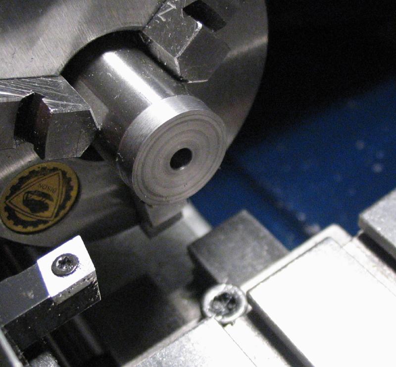
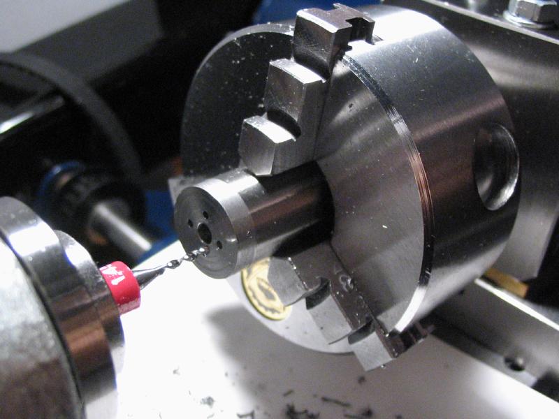
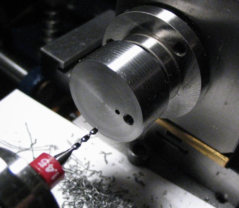
The arbor is setup in the dividing head on the cross slide with the riser block and drilled for the four screw positions (offset calculated as ~1.94mm). The arbor is returned to the headstock, and a 1.5mm section parted off to become the retaining washer. The arbor can then be tapped 1.0mm in the four holes.
Easy way to square up the head

Drill, index, drill ....
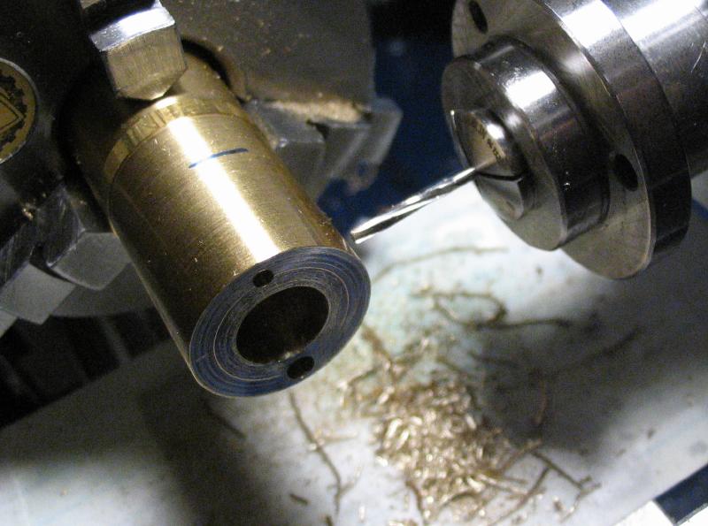
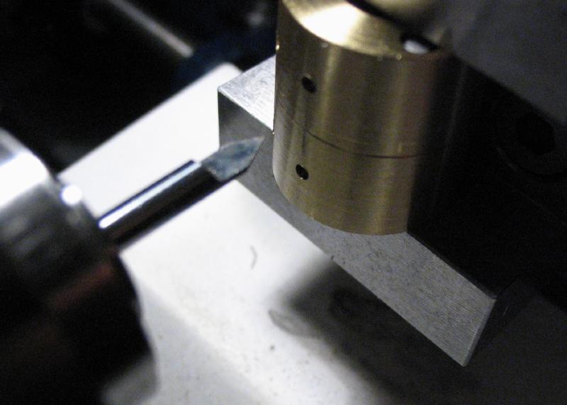
Two chamfer marks are made on the arbor as a reference for alignment after the washer is parted off.
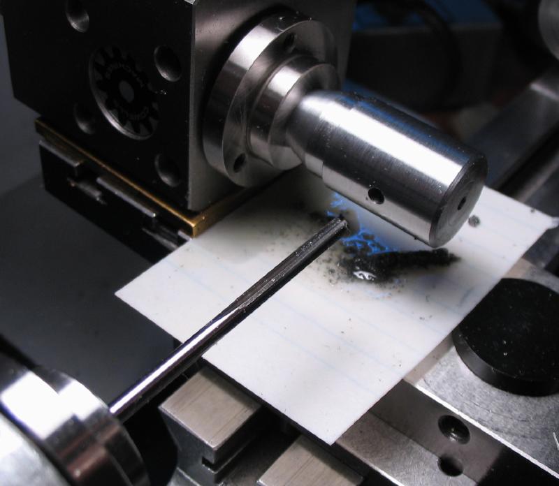
After parting, the holes in the washer are broached to pass the screws.

Tapping arrangement
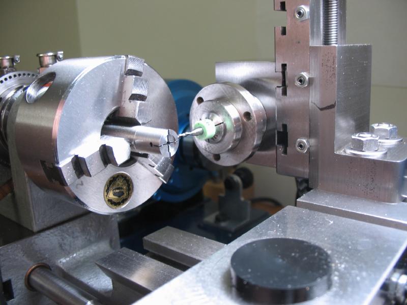
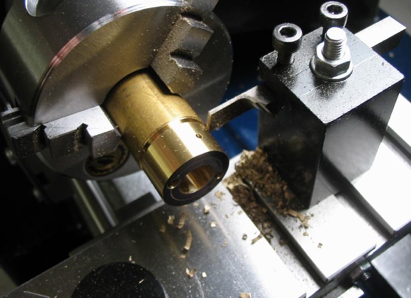
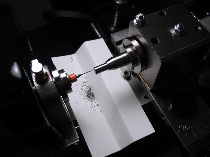
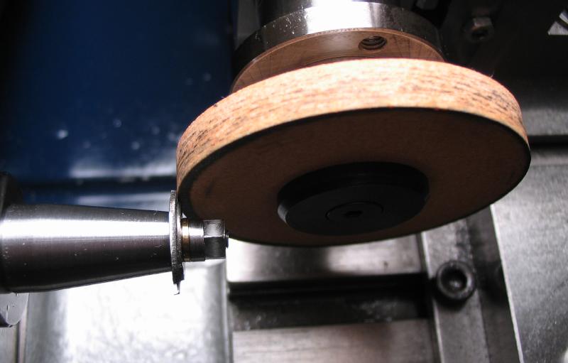
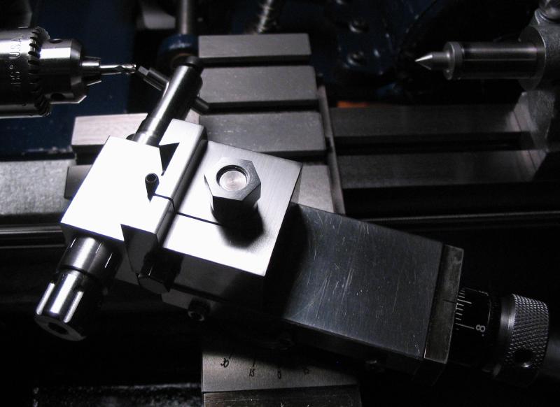
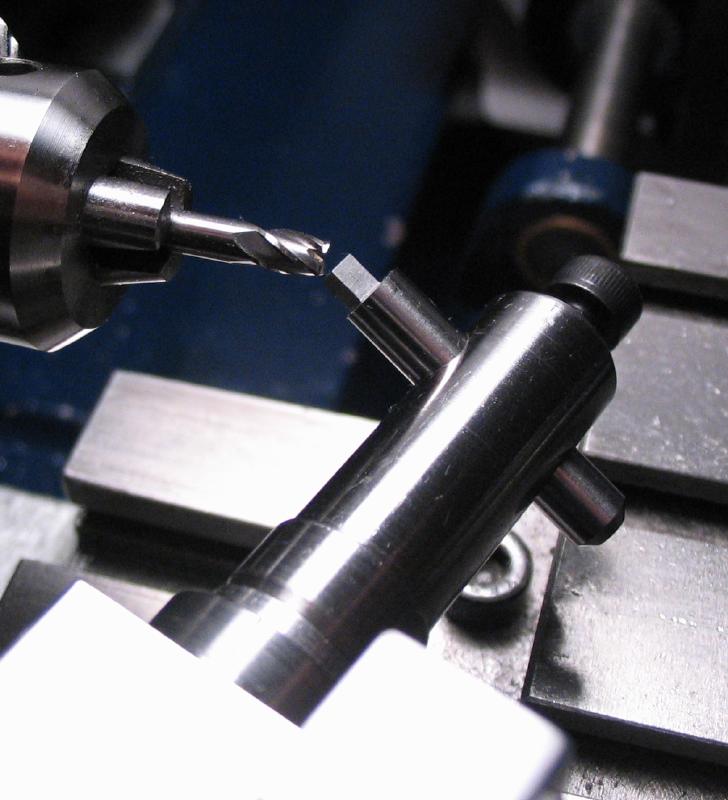
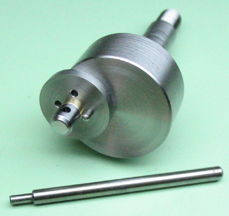
To fix the position of the wheel blanks on the arbor, spacing washers and a set of sacrificial blanks were made. These blanks are held in position by the retaining screws and have two larger holes to accept the steel spacing washers. The washers are made to snuggly fit into the crossed out space of the escape wheel blanks. This arrangement will result in the assembled components being securely fixed, hence, the wheels can not rotate on the arbor while cutting the tooth spaces. The cutters will cause burrs upon exiting, and the sacrificial blank will allow the wheel blanks to be clean cut.
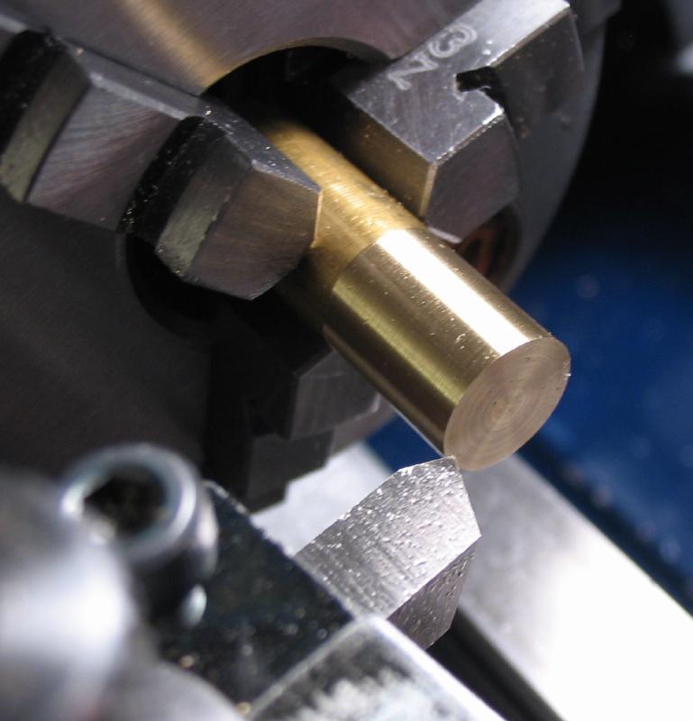
The sacrificial blanks are made from 3/8" 360 brass rod. The rod is mounted in the 3-jaw chuck, faced and lightly turned to true the diameter.
The rod is then center drilled and drilled to accept the centering pin on the arbor.
The chuck is then moved to the dividing head and end drilled in four positions. Opposing holes are drilled 1.0mm to pass the retaining screws and 2.3mm to accept the spacer washers.

The chuck is then returned to the headstock and 0.5mm discs are parted off.
A large number of these sacrificial blanks were made in the course of experimenting with cutting the escape wheel. An alternative to making them using an 8mm collet for workholding is below, however the method is otherwise very similar.
Turn 8mm portion to hold in collet
|
Transfer to collet and face
|
Turn to 9.5mm and drill 0.6mm
|
Transfer to dividing head and center
|
Drill 2.3mm and 1.0mm
|
Part off and then reface parted side on wax chuck
|
The washers are made from 3.0mm O-1 drilled rod, turned to 2.3mm and drilled 1.0mm to pass the retaining screws.
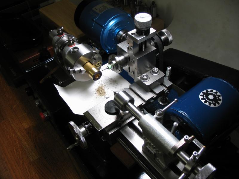
Cutters
The tooth spaces of the chronometer wheel requires two cutters, one cuts the 24 degree tooth face and included space between teeth, the second cuts the relief in the tooth back. This general method is suggested by various authors; A. Irk, G. Daniels, S. Pahlow, and J.M. Wild. I made a drawing based on the required dimensions. The cutter profiles can be taken directly from the drawing.
| Escape Wheel Cutter Details |
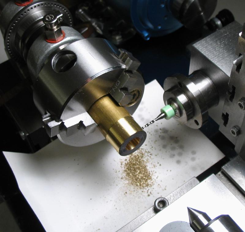
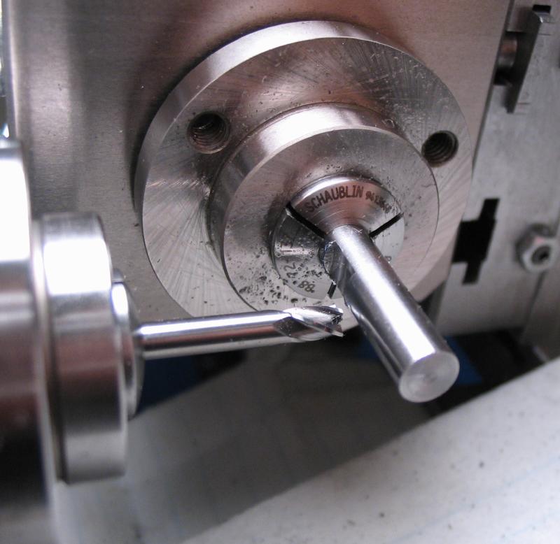
The cutter blanks are started from 16mm O-1 drill rod. The rod is held in the 3-jaw, faced smooth, center drilled, and drilled to clear the boring bar (Micro100 - BB-120500).
The rod is bored to mate the pinion cutter arbor (3.50mm). A plug gauge with steps of 3.45, 3.48, and 3.50 was made to monitor boring progress. The compound slide can be used to lightly chamfer the boring to remove burs.
Plug gauge
The rod is then turned to 15.7mm in diameter. This was chosen as a convenient diameter, since I had made a pot chuck for the winding wheels of this size. The rod is then parted off in 2mm thick discs.
The parted disc is reversed and mounted in the pot chuck to be faced clean on the reverse side.

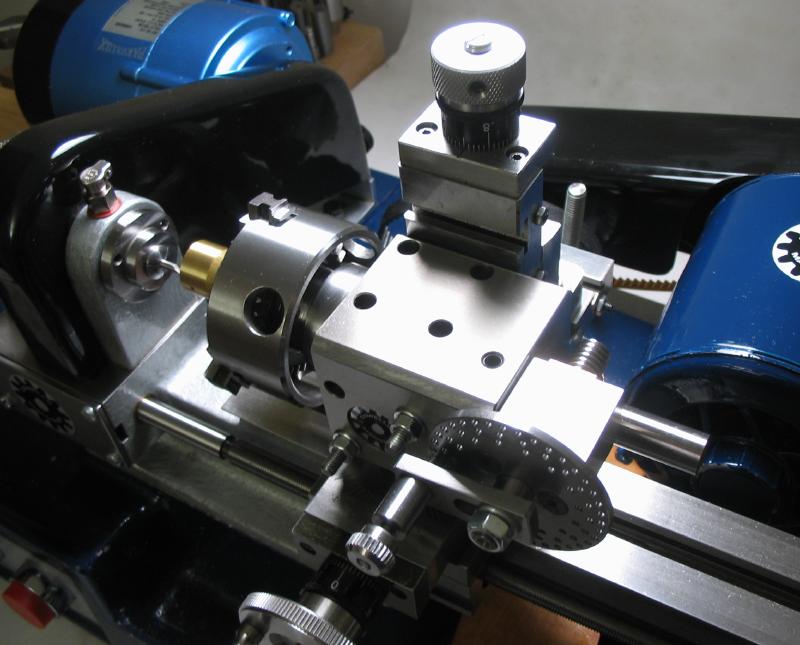
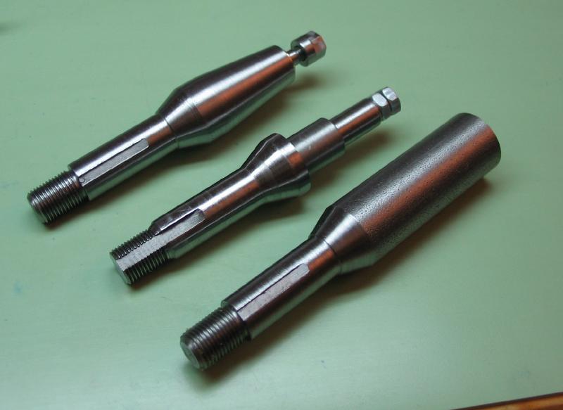
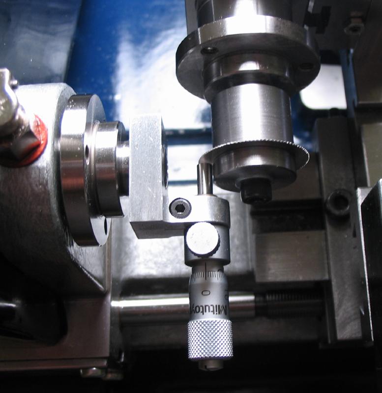
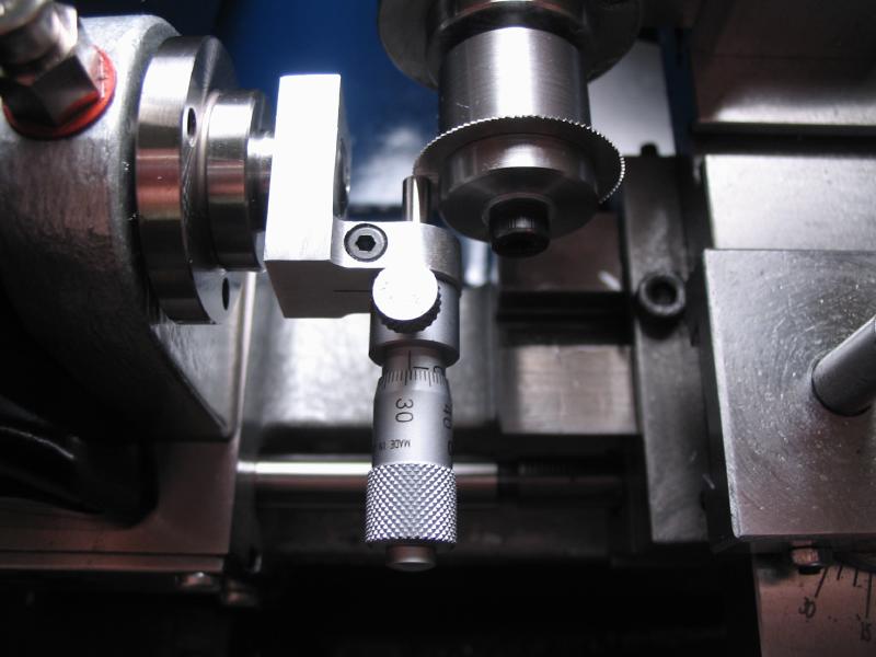
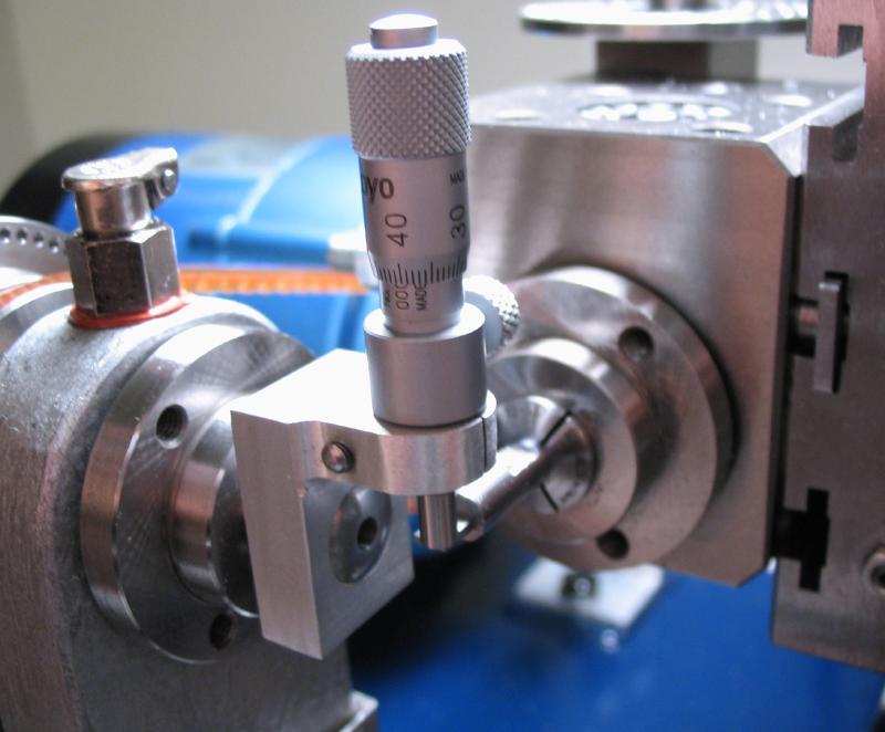
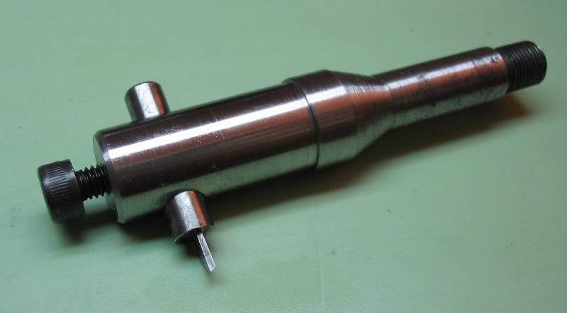
I intended to mount the cutters to the same arbor used for holding pinion cutters. However, the dimensions of my previous arbor made it difficult to use with the newly acquired micrometer centering tool. I therefore decided to make a new arbor for holding the cutters (it can also be used for holding PP Thornton cutters with 3.50mm bores).
The arbor can be started from 1/2" mild steel, and a collet-type shank is machined on one end (see procedure above for making the wheel blank arbor). However, I happen to have a couple arbor blanks that were purchased premade. The 1/2" diameter arbor is mounted in the headstock and faced down to a working length of about 30mm.
The mounting diameter is turned for a length of 8mm, with trial fit of a cutter to ensure a good snug fit is made. This length provides clearance within the bracket of the micrometer centering tool.
The end is turned down to 2.95mm for a length of 5mm to be threaded M3x0.5. Threading was performed with a die in the tailstock dieholder.
 |
 |
The supporting length of the arbor is taper turned for maximum strength and to a final diameter of 8mm at the cutter end. The compound slide was set to ~7 degrees.

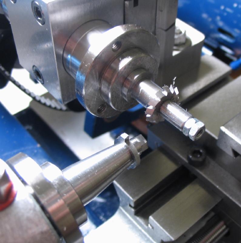
The cutter is retained by a nut. This was made from 1/4" 12L14 steel rod. Held in a collet, turned to 6mm. The rod is then drilled 2.5mm to be tapped M3. The hole is bored to a depth of 1.25mm and to pass the cutter mounting (3.5mm).
The collet and rod was transferred to the dividing head, mounted on the vertical slide. The end of the rod is given six flats for tightening with a 5.5mm nut driver. The dividing head is used to index the work, [40/6 = 6 2/3 turns] and a 1/8" endmill used to mill the flats with vertical slide movement.
Finally, the work is returned to the headstock to be parted off. The parted nut is mounted in a 6mm collet and tapped M3.
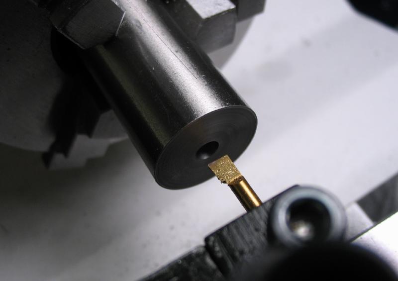
A small brass washer was turned and drilled from 1/4" brass rod.
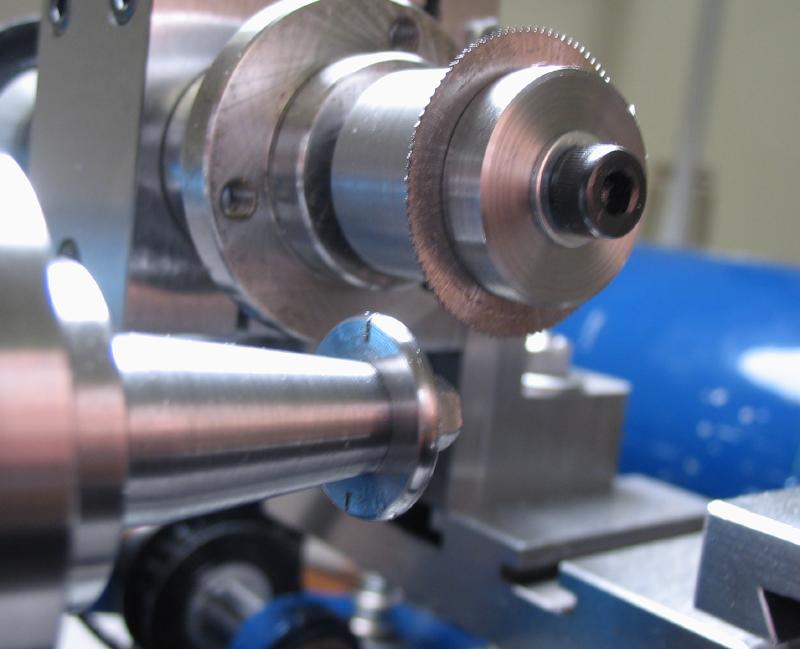
Shown are the completed arbor, the arbor made by Cowells for pinion cutters, and an unused arbor blank from 1/2" mild steel.
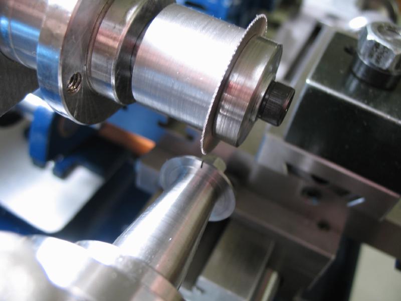
The first cutter blank was mounted on the arbor. The blank was turned to 15.5mm, and the back faced lightly to a depth of 2mm.
The front face was turned down to a final thickness of ~0.871, which is 0.05mm oversize.
A round nose cutter was used to approximate the rim radius of the escape wheel.
The face of a 0.012" slitting saw was aligned with lathe center.
The cutter was slit at two positions, 180 degrees apart. These will be the cutting faces of the finished cutter.
A ratchet (angle) cutter was used to mill the cutter relief.
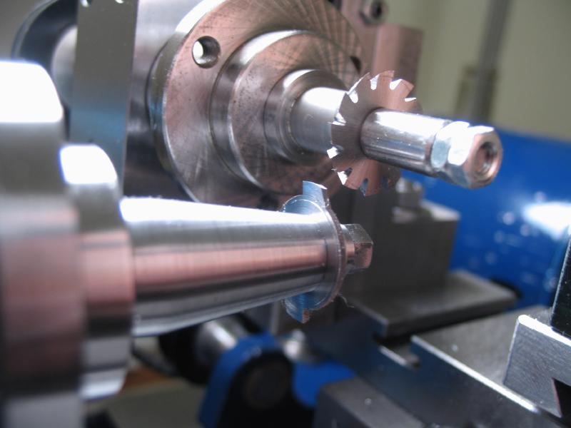
The second cutter is mounted on the arbor, and a relief cut turned on the face.
The cutter is turned true, to approximately 15.5mm.
The radius was turned by hand with a graver on the T-rest. The radius was checked using a steel plate which had been driled 1/8".
The slotting saw was set on lathe center. Since the cutting face is reversed, the micrometer was set to 0.305mm.
The cutter was slit in two opposing sides, indexing with the headstock.
The single angle cutter was used to mill the recesses.
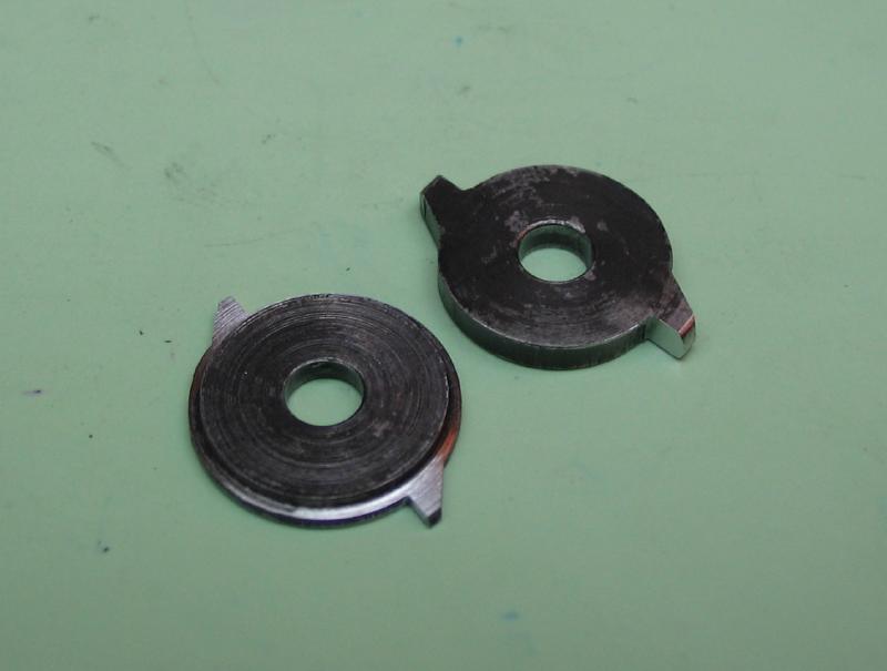
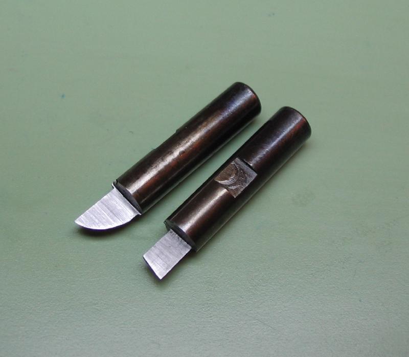
The two cutters with the major machining completed.

The cutters were hardened in oil.
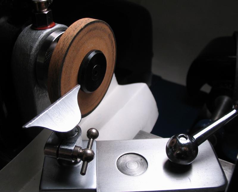
The cutting faces can now be ground, I used a 400 grit wheel setup on the wheel and pinion cutter attachment.

The grinding face is set to lathe center.

The cutter faces were then ground flat.
 |
 |
The process was repeated for the first cutter as well.
In addition, the cutter was left oversize by ~0.05mm, the side of the cutter can now be ground to the final thickness of 0.821mm, checking with an accurate micrometer.
The completed cutters.
Fly Cutters
The cutters described above did not prove satisfactory in use, I suspect it is the lack of relief or rake in the cutting edges. Although the same style of cutter could have been remade with modifications, I decided to try the fly-cutter method described in J. M. Wild's book "Wheel and Pinion Cutting in Horology." I envisioned using the dividing head to position various cutting surfaces for milling relief. There are a few edges that will have to filed by hand.
The cutters were redrawn and profiles changed, especially for radius cutter.
| Escape Wheel - 5mm Fly Cutter - Gashing |
| Escape Wheel - 5mm Fly Cutter - Radius |
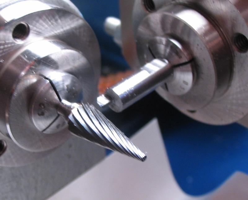
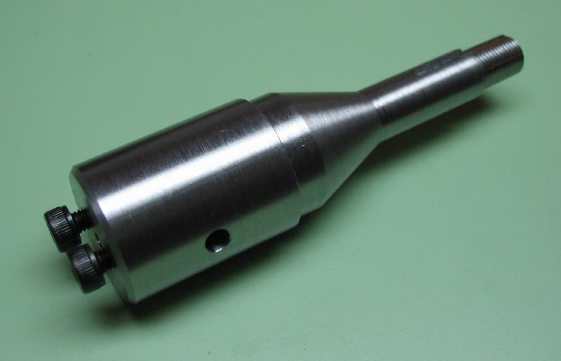
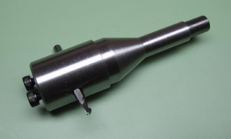
To hold the cutters another arbor is required. 1/2" steel rod with a collet shank machined on one end was then mounted in the headstock and the working end reduced to 30mm in length and 11.5mm in diameter. The end was drilled 3.3mm and tapped M4x0.7. This is for the securing screw, for which I am using a stock M4 socket head screw.

The arbor was then mounted perpendicular in the dividing head and on lathe center. The mounting hole is drilled through (4.9mm) and then reamed with a 5.0mm chucking reamer (Lavalle-Ide # 533.1969).
 |
 |
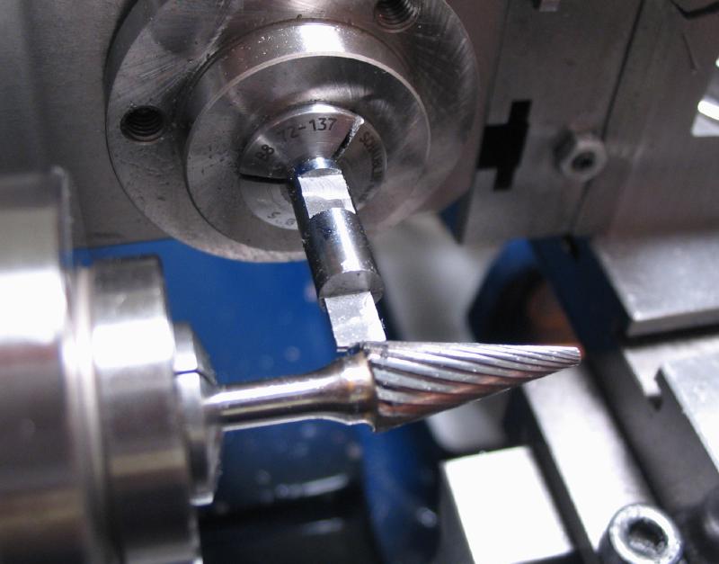
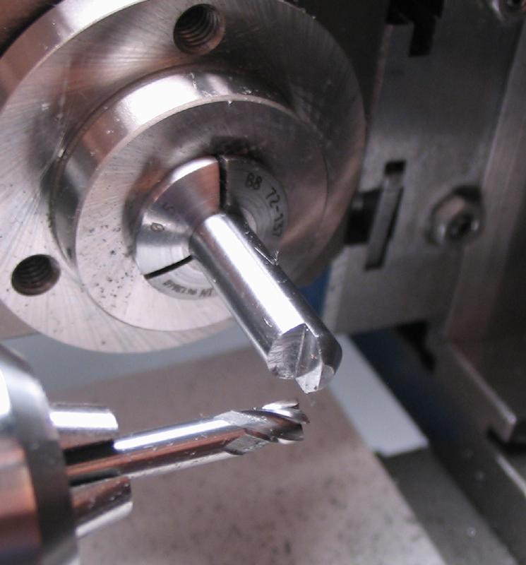
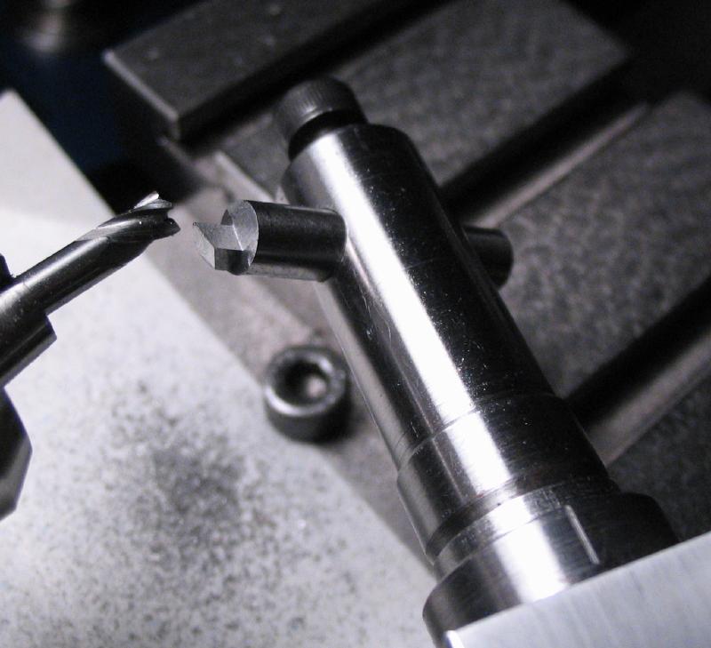
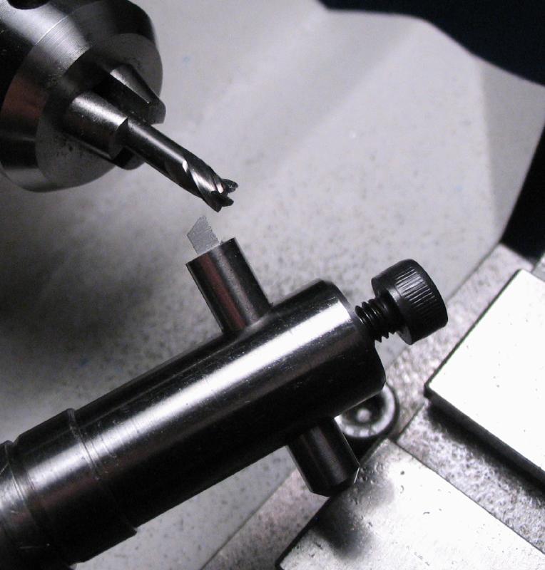
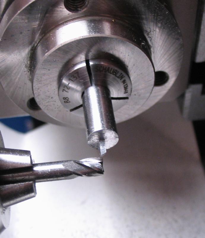
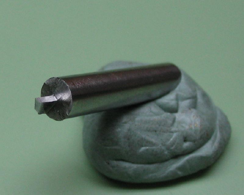
The Gashing Cutter
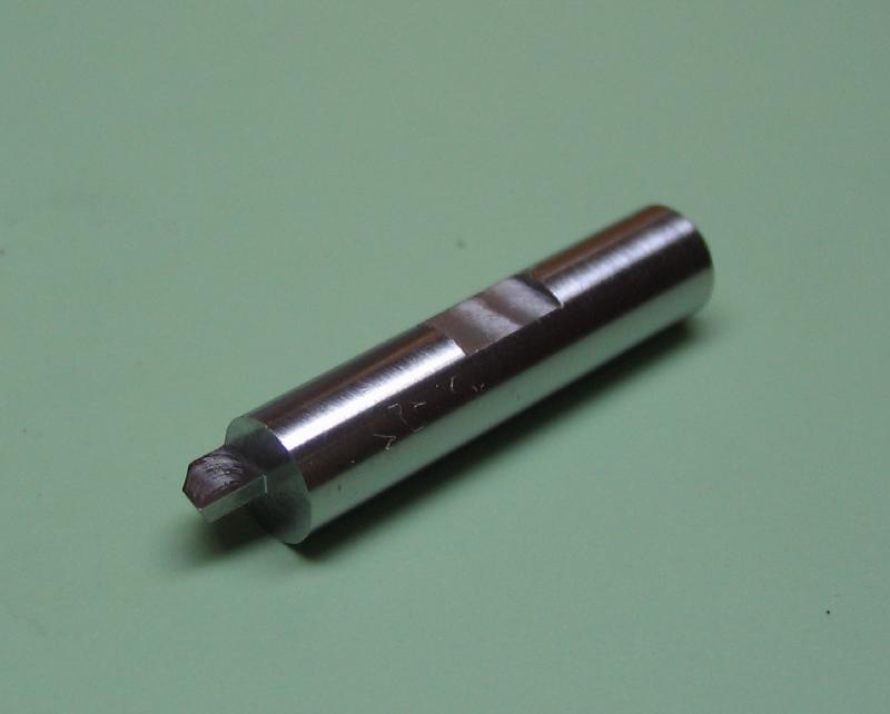
This cutter was made from 5.0mm O-1 drill rod. A 26mm length of rod was mounted in the dividing head on the vertical slide. The divisions were prepared for 120 (3 degree increments). A 1/8" end mill was mounted in the headstock in a collet. First a "Weldon flat" was milled to provide a reference surface for the securing screw in the arbor.

The top face was given 9° (one rotation of dividing head) of relief.

The bottom was milled flat.
The side cutting surfaces are then milled. The rod is turned 93° (10 + 1/3 rotations of dividing head) and the left side of the cutter is milled (at least the bulk of it was).
The opposite face was milled with 3° of relief as well.
The faces are finished up, bringing the thickness close to final size. It will be finished by stoning after heat treatment.
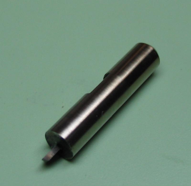
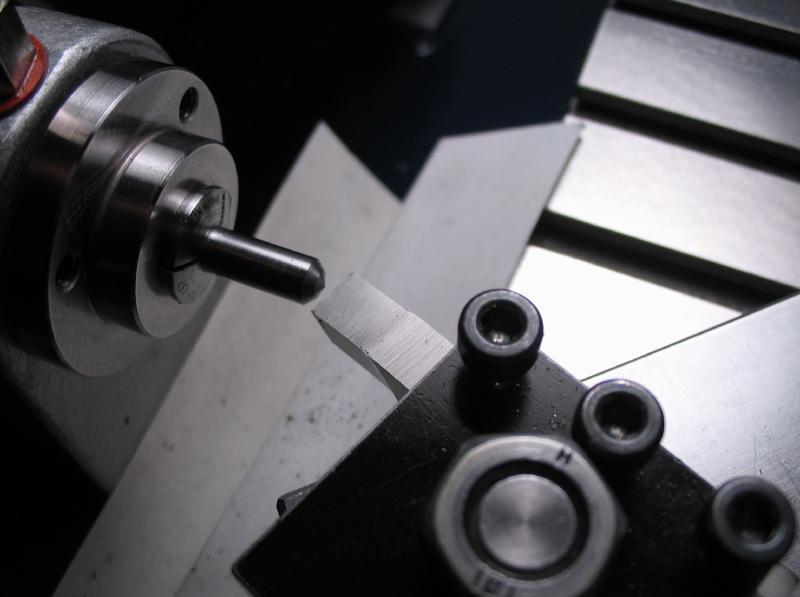
The relief on the tip of the cutter was formed by filing and checking with a machinist protractor to approximately 10°. The cutter was offset 1.66mm and carefully milled with a 1/4" end mill to give the shape of the outer wheel rim.
 |
 |
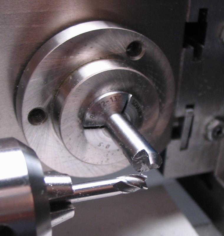
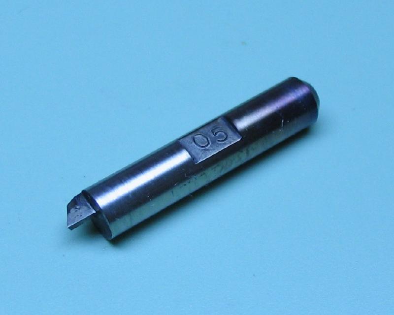
Gashing Fly-Cutter No. 2
The gashing cutter was remade using the same method as described except the step for forming the curvature on the tip. The endmill method does not provide any cutting relief. The second time, I used a SM-51 cone bur (22 degree included angle). This bur is 1/4" at its largest diameter, thereby a curvature can be given which is close to the desired radius. The fly cutter was offset using the micrometer centering tool.
 |
 |
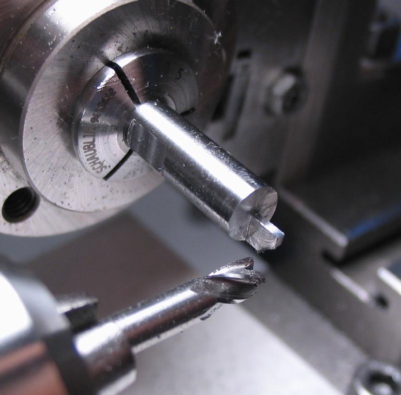
Gashing Fly-Cutter No. 3
A third gashing cutter was made, the primary change being that the cutter face is on the center line. This was neglected in the previous attempts above. Another small change is that the some relief was turned onto the bit in the beginning using the topslide to put a 45 degree taper onto the blank.
|
|
|
|
|
|
|
|
|
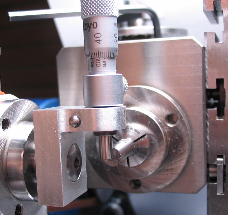
Gashing Fly-Cutter No. 4
The fourth version was made the same as the third, but the cutting edge angle and rake was turned using the topslide on the lathe.
|
|
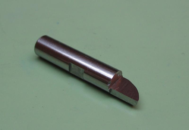
Gashing Fly-Cutter No. 5
The fifth version was started by milling half-way to form the cutting face and the sides of the cutter were started but left oversize for the next step.
The cutter was removed from the dividing head and secured in it's arbor. The arbor was mounted in the collet-holding toolblock which was squared to the topslide in it's tool post clamp. The topslide was set to 21 degrees to approximate the shape of the tooth space bottom. It would be ideal to be rounded and blend in with the natural shape of the wheel hub, but this is my best compromise. The collet-block can be adjusted to form the clearance angle of about 45 degrees.
The setup before milling cutter tip face.
|
|
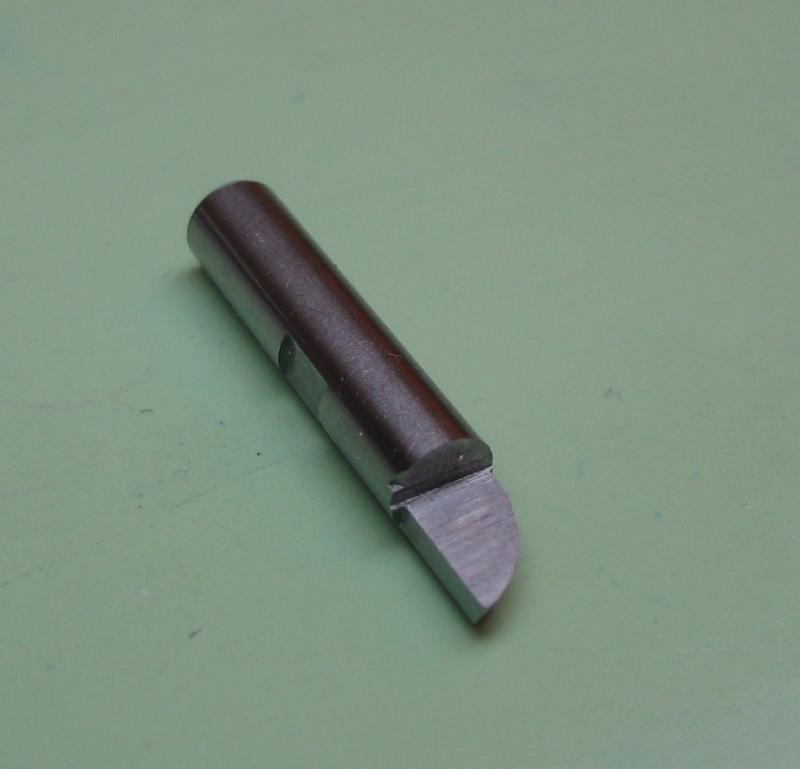
Photos after milling the tip. The cross slide and leadscrew were used to feed the work.
|
|
The cutter is returned to the dividing head for finishing to final thickness. The sides were milled to give 3 degrees of relief from the cutter face.
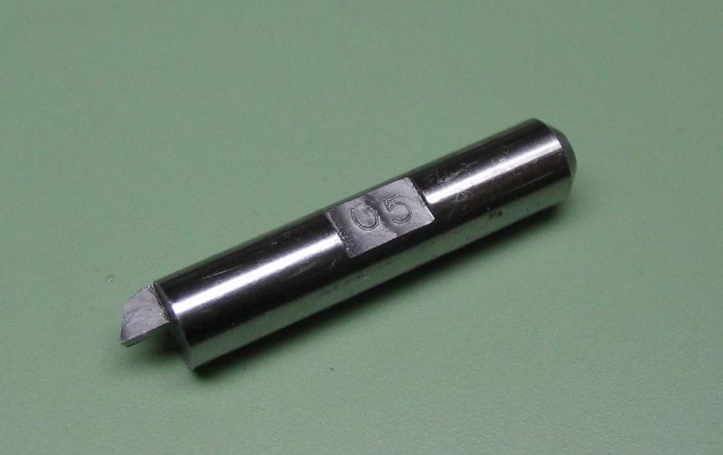
With the milling complete, the cutter was touched up on an Arkansas stone slip. Since I am accumulating a number of different versions of cutters, I decided to stamp the number on the locking flat. The cutter was then hardened in oil. After cleaning up to observe color change, it was gently heated with the alcohol lamp to temper to a light straw at the tip.
|
|
|
Multipoint constant-profile gashing cutter
A different approach to making the gashing cutter is described here. I will be following the method described in J. Malcolm Wild's book, "Wheel and pinion cutting in Horology" for making a constant profile, multi-point cutter. A work-holder needed to be constructed to hold the cutter blank off-center to machine the four profiles. Wild describes the construction of a larger sized cutter and uses a brass holder held in the 3-jaw chuck. I decided on a smaller sized cutter and the use of a holder that can be mounted in the collet-holding headstock of the lathe for greater rigidity. The holder is designed such that the cutter blank is held off-center and can be indexed through four positions.
A length of 1 inch mild steel (12L14) was mounted in the 3-jaw chuck and supported in the steady rest to face each end and center drill for tailstock support. The tailstock center is installed and the basic dimensions for a collet shank are machined. Details are given in various places on this page already, but photos were taken along the way and shown below.
A CAD drawing was made to help visualize the machining process for the cutter and is attached below.
| Multi-point Gashing Cutter |
Face & center-drill
|
Turn to 1/2"
|
Turn to 8mm and for threading B8
|
M6.82x0.625
|
Taper 20 deg.
|
Mill 2mm keyway
|
The cutter blank will be secured with a shoulder screw. The screw was turned from 5mm O-1 drill rod. A length of 4mm was turned to just over 3.5mm and finished by stoning to mate the bore in the cutter blanks. A length of 10mm was turned to 3mm to be threaded M3x0.5. The head was turned down slightly just to provide clearance and cross drilled 2mm for tightening. It could then be hardened and tempered blue and repolished.
|
|
|
|
|
A washer was made from 1/4" brass rod, drilled and reamed to 3.5mm, turned down to ~4.9mm and parted off.

|
|
A tommy bar to assist with the screw was made from a length of 1/8" drill rod and turned to 2mm. It was hardened in oil and tempered to a light straw color.
|
|
The cutter blank was made in a similar manner as was done above. A length of 16mm O-1 drill rod was mounted in the 3-jaw and faced, drilled, bored and reamed 3.5mm. The diameter was reduced to about 15.7mm to fit a pot chuck already on hand, but will be reduced later on. The chuck and work was transferred to the dividing head to drill and ream four indexing holes (1/16"). The work is returned to the headstock and parted off at about 2.5mm in thickness. The parted side was then faced using a pot chuck.
|
|
|
|
|

The dividing head was mounted on the cross slide and centered with the micrometer. The work was then offset 8mm as per the drawing above. This position was drilled 2.5mm and tapped M3x0.5 for the screw made above.
|
|
|
The cutter blank can now be attached and the position for the index pin is aligned with the pin held in the headstock with a 1/16" collet. The position is then drilled and reamed to 1/16".
|
|
|
The resulting components and setup ready for machining.
|
|

The radius cutter
This cutter was started much the same way, a mounting flat was milled and then the end milled flat to half the width of the rod (2.5mm). This will be the top face of the cutter.
The left side was milled 0.5mm to provide clearence.
The opposite face was milled to a depth of 0.25mm and with a 12° rake (1 1/3 turns on dividing head).
The cutter and collet were transferred to the collet holder mounted in the adjustable vise. The radius was formed with #2 and #6 hand files.
 |
 |
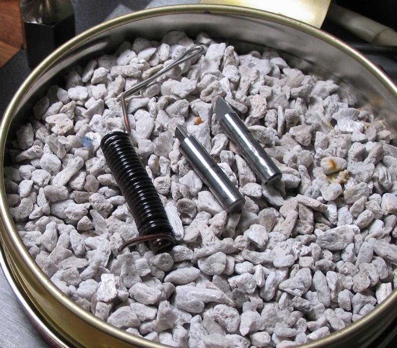
The cutters are hardened in oil using a wire basket. While heating the cutters I finally observed what I think William Smith was referring to when he describes the "disappearing shadow" method of heat treatment in his Tooling the Workshop video. The heavy wire basket glows red first, and the cutter appears only as a dark color as observed from the top while heating. The cutter slowly comes up to temperature, and the dark color (the shadow) disappears and begins to glow as well. At this point the cutter is quenched.
They are then tempered so that the cutting tip is a light straw color.
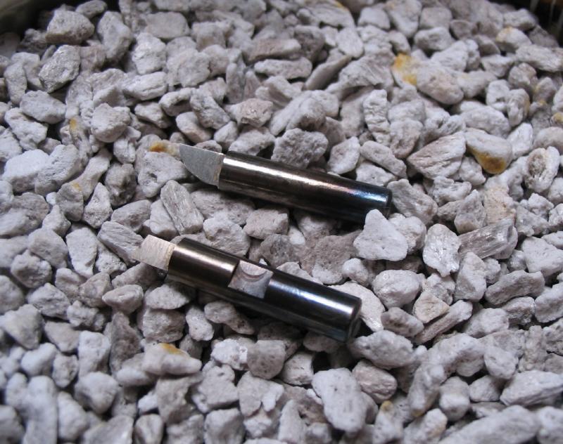
The cutters are sharpened on stone slips or touched up on the 400 grit wheel.
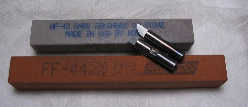
A Fine India square stone and square Hard Arkansas stone.
A Fine India square stone and square Hard Arkansas stone.
Radius fly-cutter from a 1/8" ball endmil
| ball_nose_end_mill_radius_cutter.pdf |
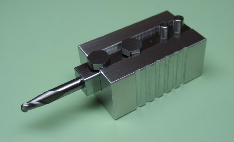
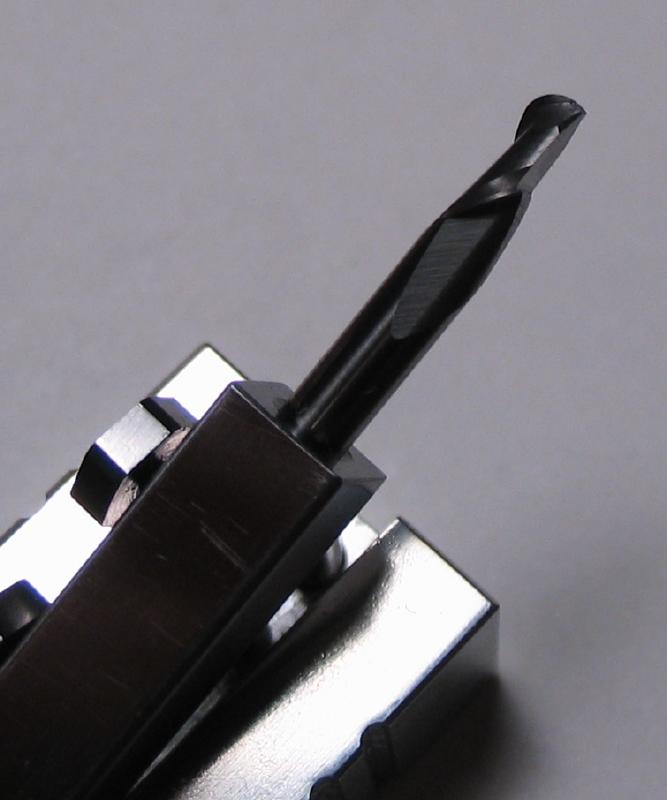
The radius cutter was not quite correct in shape to produce the tooth shape that was desired. A new one could have been made, but after reading a discussion on the topic on the NAWCC message board, it was suggested that a ball endmill be used as a fly cutter. The mill bit will need to have clearance ground onto one edge of to fit within the tooth space. As seen in the drawings above, the radius of the curvature of the back of the escape tooth is very close to 1/16". A 1/8", 2-flute ball end mill will be used. Approximately half of the ball end will be ground off to leave a single flute at the tip which will have a radius of 1/16". Not having a convenient means of grinding carbide, a jig was constructed to hold the endmill and maintain some reasonable accuracy while grinding the tip against a diamond bench hone.
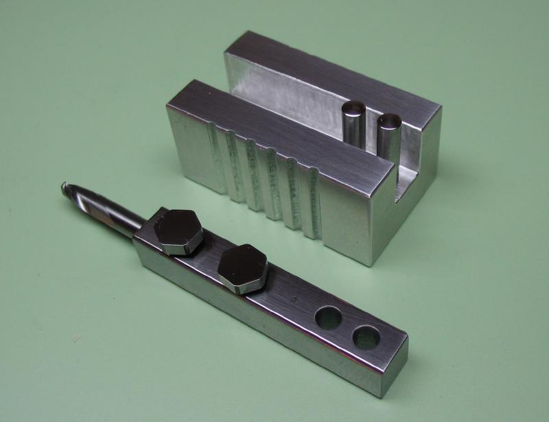
The jig was made from a piece of scrap aluminum bar. It was milled on all sides to make reasonably square and then a central 1/4" channel was milled. Two holes were drilled and reamed 2mm to place guide pins. When planning this project, I accidentally purchased a 1/16" ball endmill, apparently not thinking very clearly. So to make some sort of use of the bit, I milled some grips into the sides of the jig. Really not necessary, and by and large the whole jig is a bit over engineered!
|
|
|
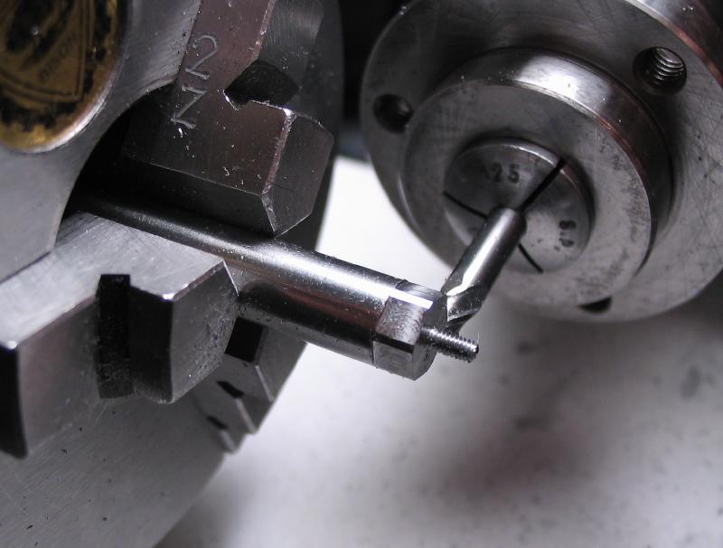
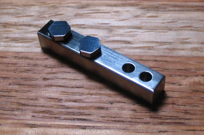
The holder was made from 1/4" square mild steel bar and was drilled and reamed axially to hold the ball endmill, drilled and tapped 1.5mm for set screws, and drilled and reamed 3mm for the guide pins. Set screws were made from 6mm drill rod, turned and threaded 1.5mm and the heads milled to a hex shape with a width of 5.5mm (the smallest wrench on hand). The screws were hardened and tempered blue, and polished on emery paper. The guide pins were turned from 3mm drill rod to just over 2mm to fit the jig base.
Not many photos were taken during the process.
|
|
|
|
The finished jig with ball end mill held in place.
|
|
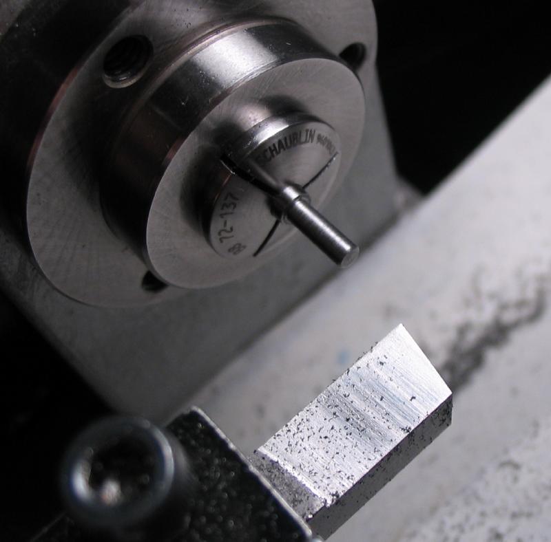
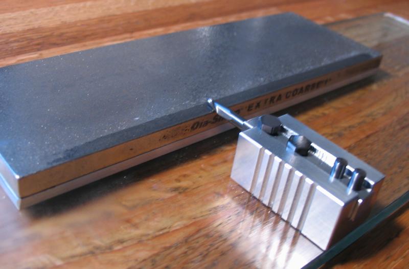
The jig is shown in use with a DMT brand, extra-coarse diamond hone. The time to grind off the tip was surprising quick. The edge was finished on a fine diamond hone, although not necessary.
|
|
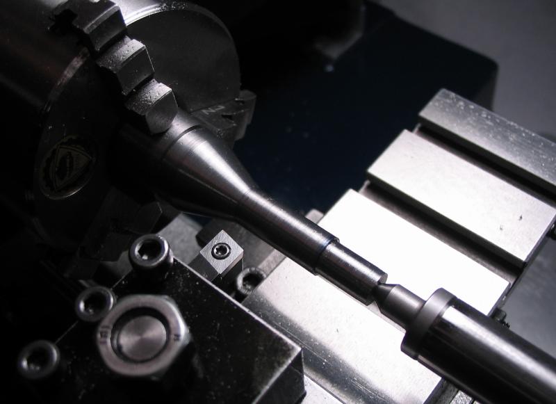
An arbor was made to hold the radius cutter. It was made from 3/4" mild steel rod using the methods described above for other collet-shank arbors. The working end was drilled 3mm and reamed 1/8" for the radius cutter bit (the ground endmill), and then end drilled 2.5mm in two positions for tapping M3x0.5. Two M3x12 socket head screws are used to hold the cutter in place.
|
|
|
|
|
|
|
|
|
