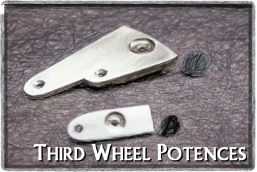
Third Wheel Bridges
This page will describe the fabrication of the upper and lower bridges/cocks for the third wheel (and the carriage).
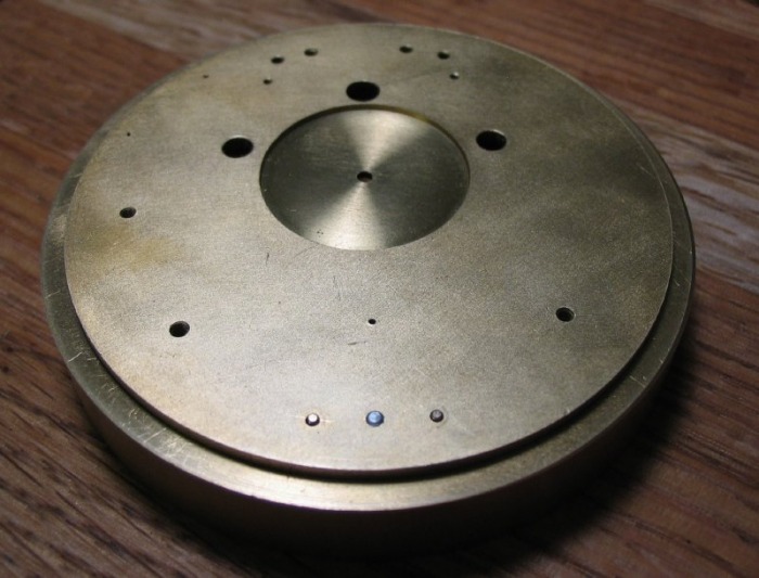
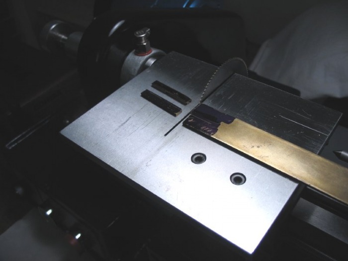
The lower potence is made from 1/16" brass plate. A piece was sawn out of sufficient size to be held on the faceplate with clamps. Sawing was done with the recently acquired table saw attachment for the lathe (see the end of the Cowells 90CW section), which made easy work of it, sawing through the brass like butter!
The plate was made long enough so that a center could be made and with the compass an arc scribed onto it which is the inside diameter of the mainplate's dial side rim. This was then cut out with the piercing saw and finished with a file. The plate can then be fit against the rim (its eventual location).

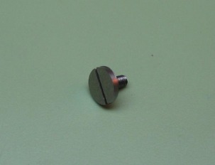
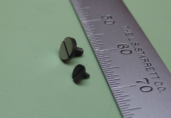
A screw was made to secure the potence in place. It's head is 4.25mm in diameter and 1.25mm thick, the threads are 1.5mm.
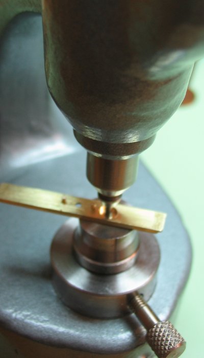
The position for the screw was determined by fitting the screw as close to the edge as possible. The plate was mounted with support on the drill press and chamfered, drilled 1.25mm, and tapped 1.5mm.
The hole in the potence plate was broached open to clear the screw. The plate was then tested for fit, which it passed, of course.
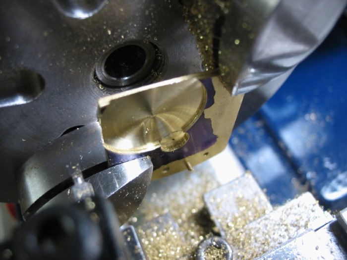
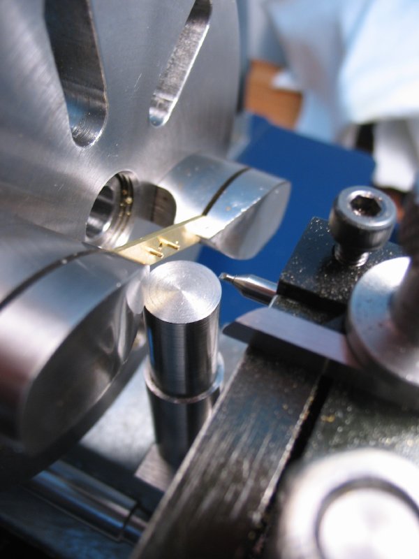
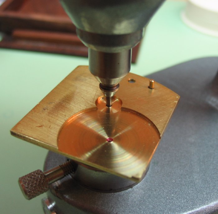
A custom made counterboring tool was made, with a removable 1.50mm center pin and a 4.25mm cutting face. This was made using the Shadle method described in the toolmaking section. The potence plate was clamped on a tailstock drill pad using a toolmaker's clamp, and the piloted counterbore mounted in a 5mm collet in the headstock. The thickness of the screw is 1.25mm.
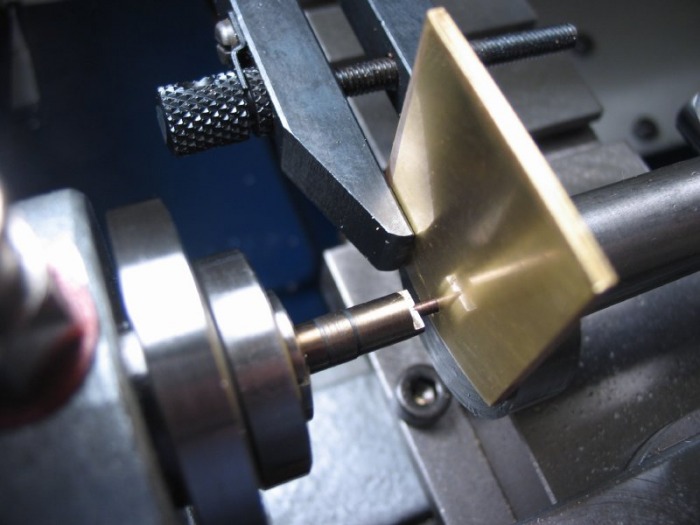 |
 |
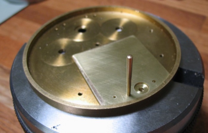
Once the plate can be secured to the mainplate with its screw, the steady pins can be installed. The method I chose to use, I found in John Wilding's book on making an English regulator clock. It is the technique he describes for fitting the steady pins for the movement plates. It involves fitting brass taper pins. The positions are drilled undersize through both the plates.
 |
 |
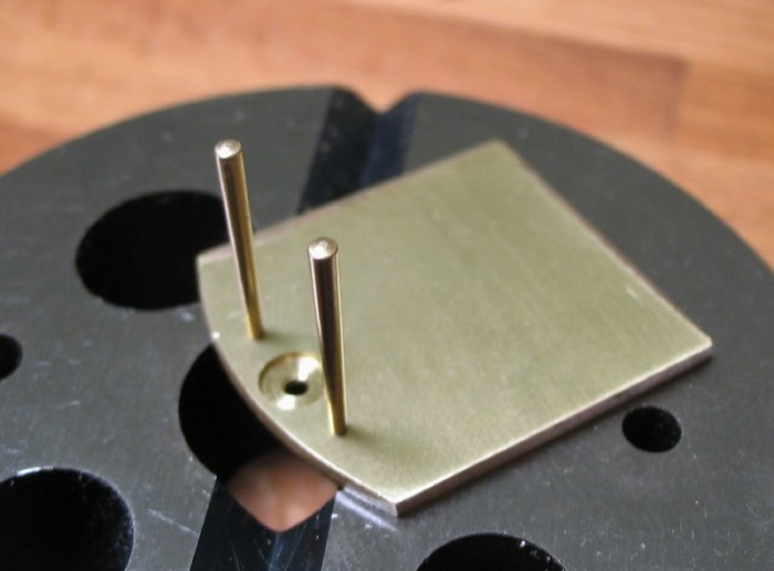
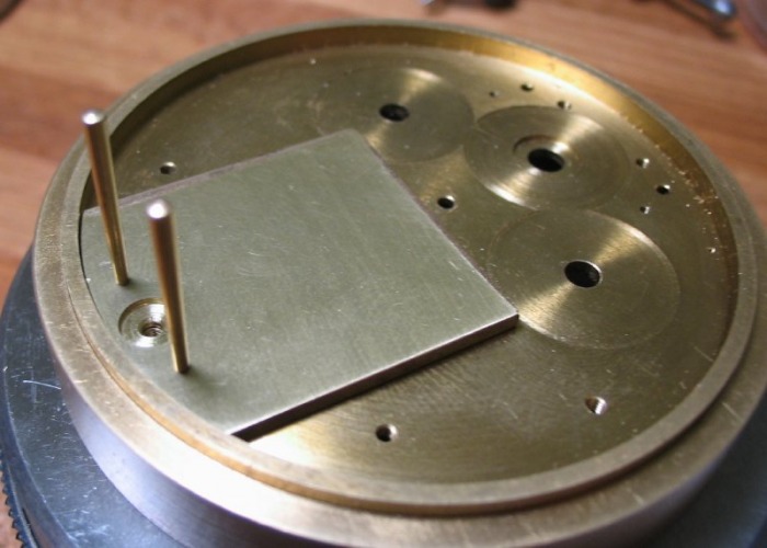
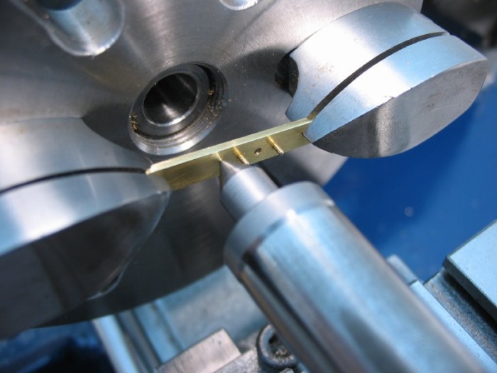
With the holes drilled to allow the pins to enter, the holes in the potence plate are broached open to allow the pins to enter about half way. One pin is hammered into the plate. It will enter the mainplate, but not fully down, this hole is then broached to give a snug fit to the pin when the plate is in position. Afterwards, the second pin can be fit to the potence plate and then to the mainplate.

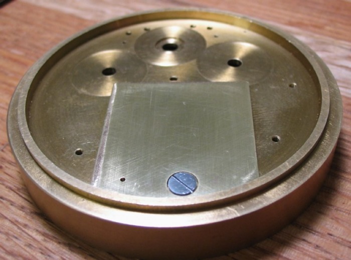
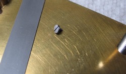
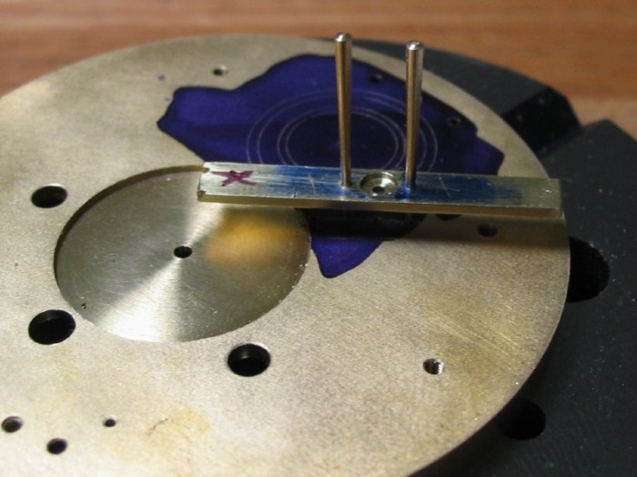
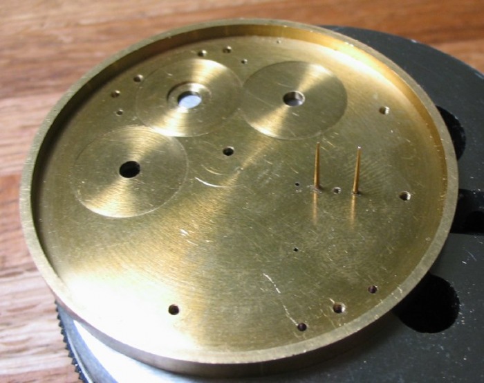
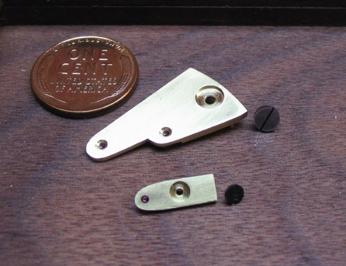
The pins can then be sawn off and filed flush with the top of the potence and flush with the mainplate when installed. The photo is after rubbing with fine emery, they are visible to the naked eye, as the brass of the pin is slightly more copper colored, however they are virtually invisible to the camera. Ignore that extra hole, it will be cut away later on... Also, on the mainplate side, they could be made a little more flush...
 |
 |
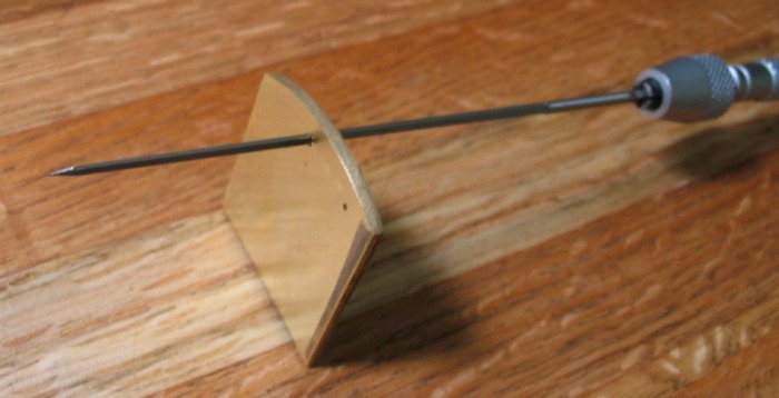
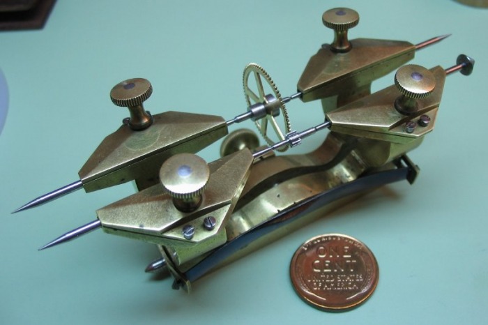
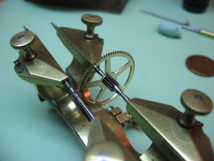
The position for the third wheel must now be determined, and it seems to me that this must be done prior to the union of the third wheel and its pinion. Is it a chicken & the egg situation; the pinion can not be finished until the final dimensions of the plates are found, but the wheel and pinion are needed to finish the plates... Therefore, separately, the third wheel is depthed to the carriage pinion, and the center wheel to the third pinion. The third wheel is mounted to the test arbor that was made for the purpose of checking the poise of the balance wheel during its fabrication. This allows the third wheel to be mounted in the depth tool, without its pinion. The depth is determined and a radius scribed onto the top plate from the seconds position (carriage pinion pivot).
The depthing process is repeated for the center wheel to the third pinion.
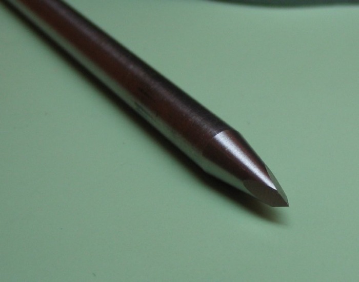
The depths are planted onto the mainplate. The intersection of the scribe marks is found and chamfered. I recently rediscovered that my staking set has a chamfering punch, which is a three faceted, sharpened pointed, which when twisted into the plate, makes a small chamfer. The staking anvil keeps the tool upright.
 |
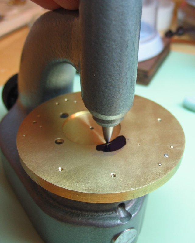 |
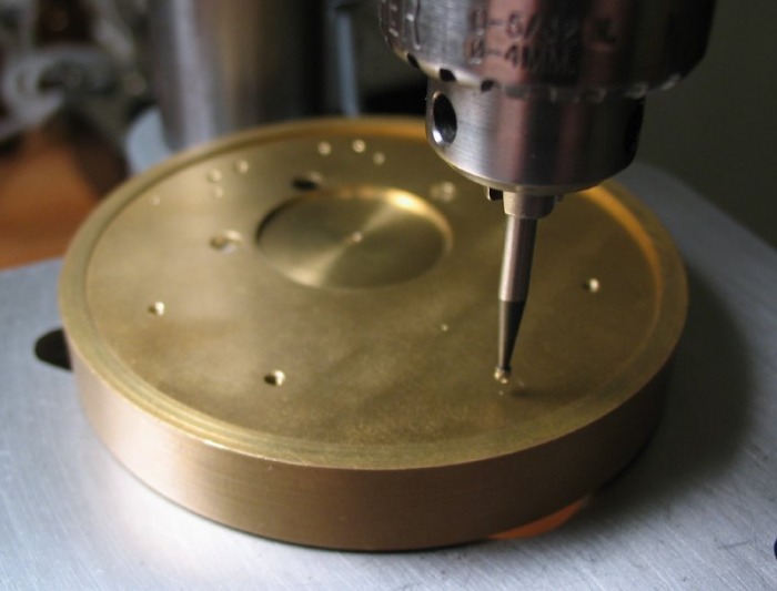
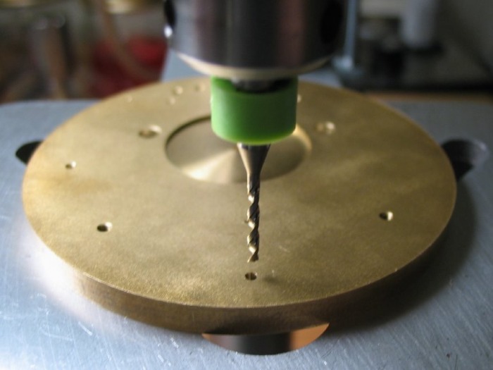
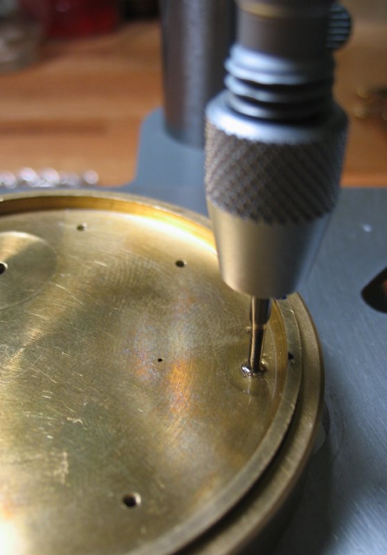
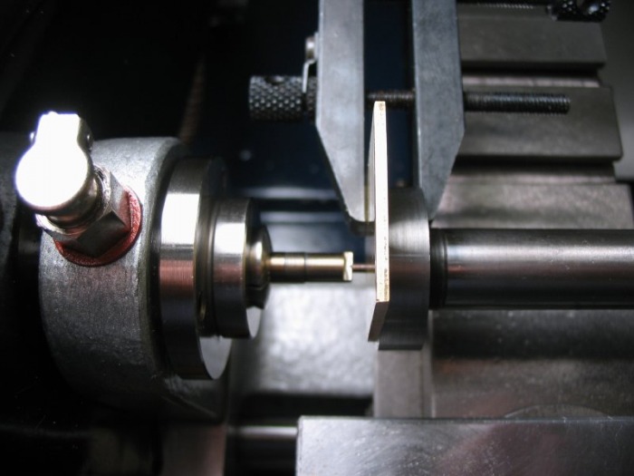
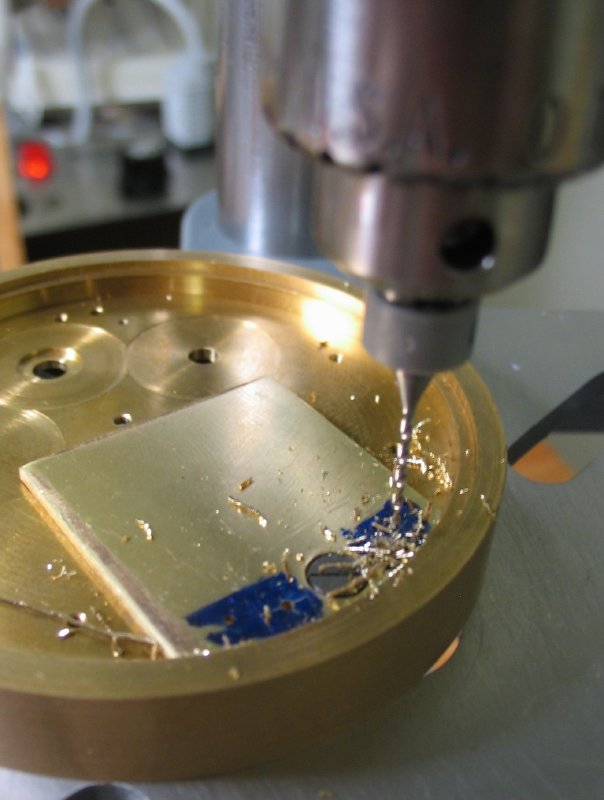
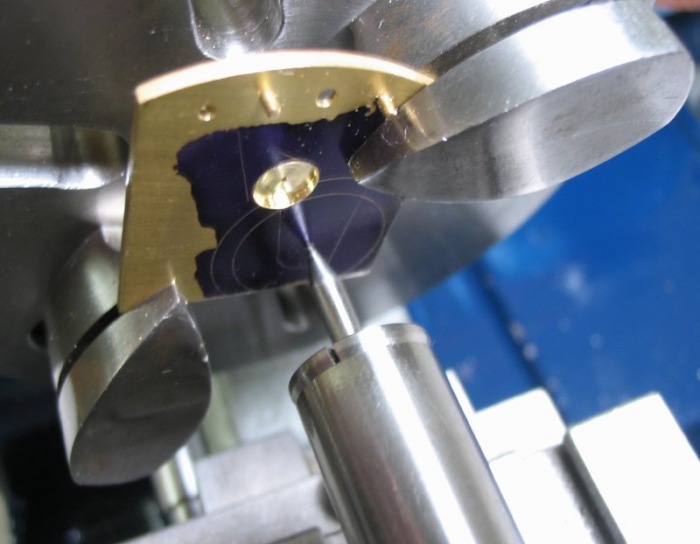
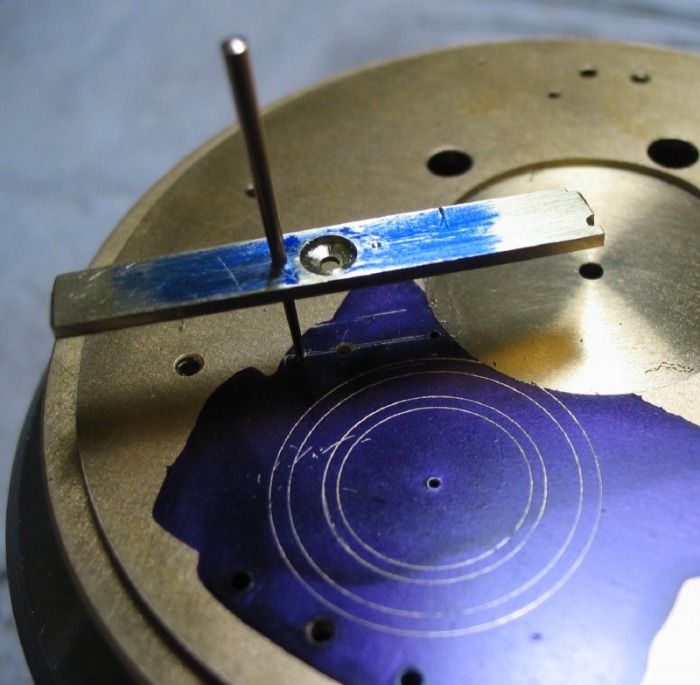
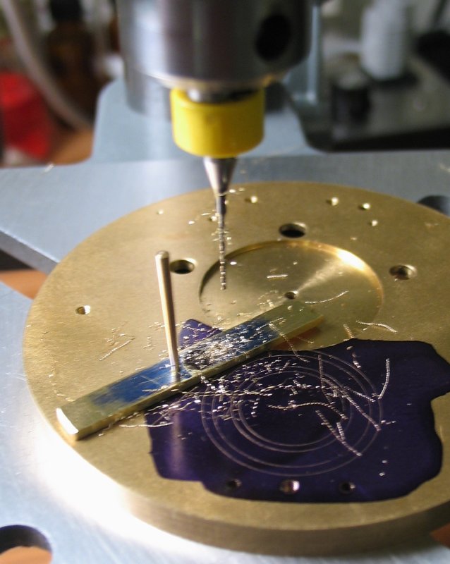
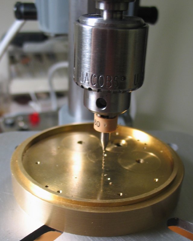
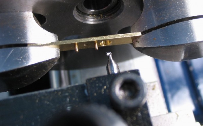
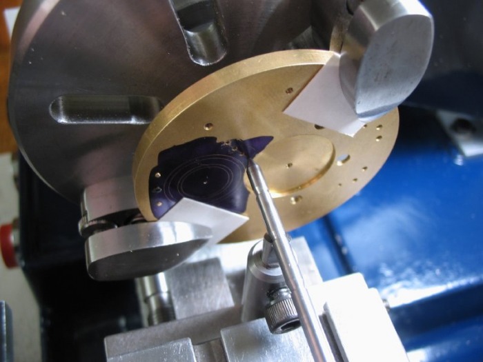
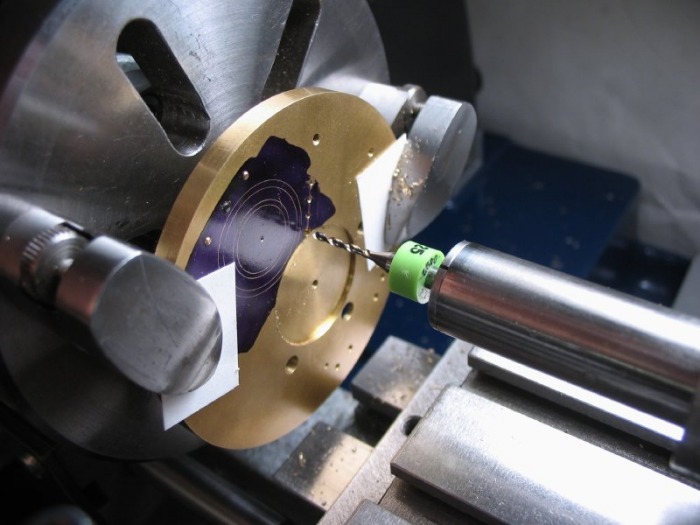
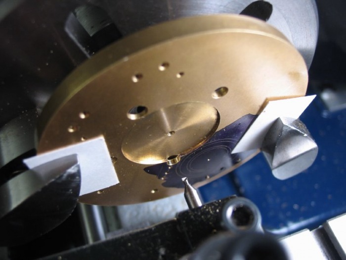
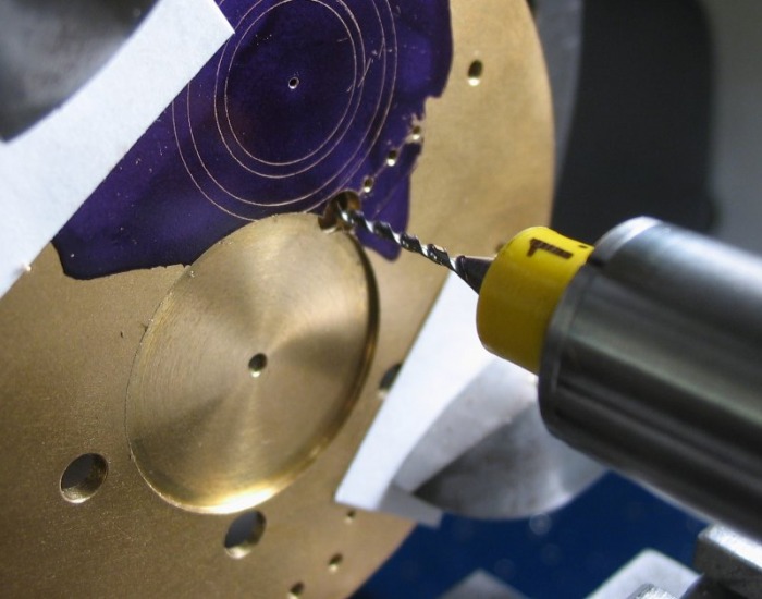
The position can now be drilled undersize (0.60mm) through both the mainplate and through the attached potence plate as well. Although Daniels does not say so, I decided to drill through the 'seconds' hole into the potence plate as well (0.50mm), since the plate needs to be scribed later from this position. I imagine he simply forgot to mention it.
 |
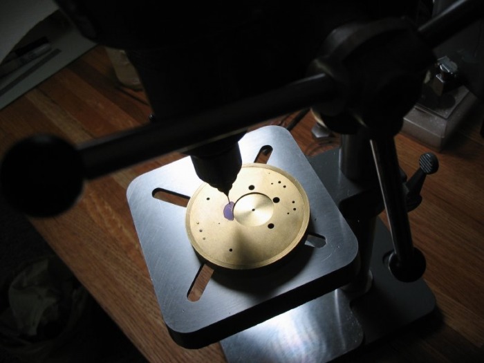 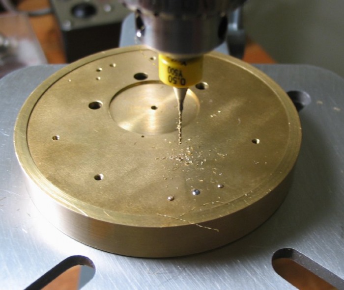 Drilling the 'fourth' position |
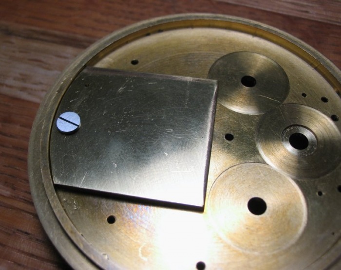
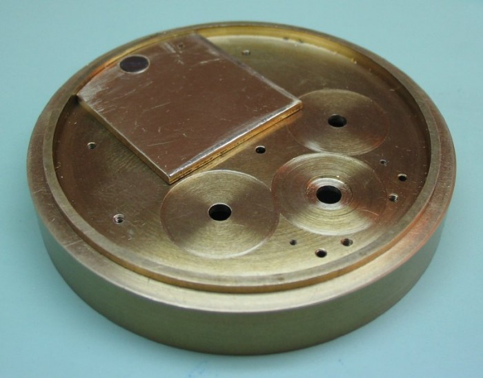
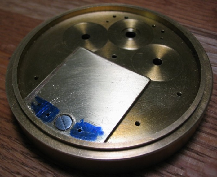
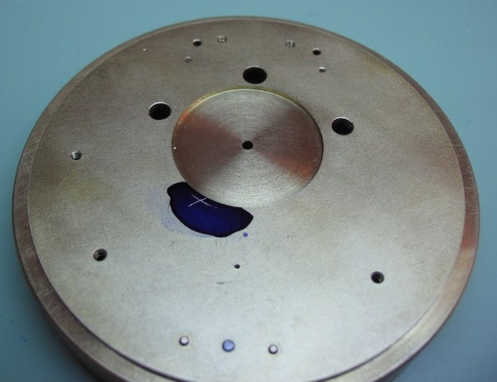
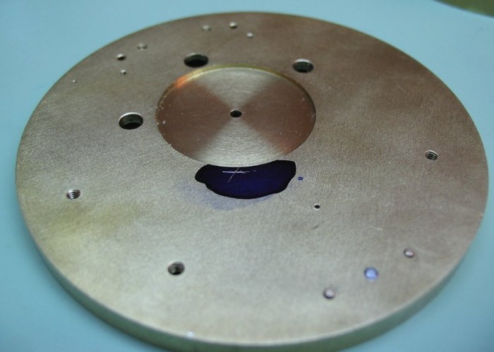
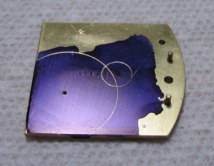
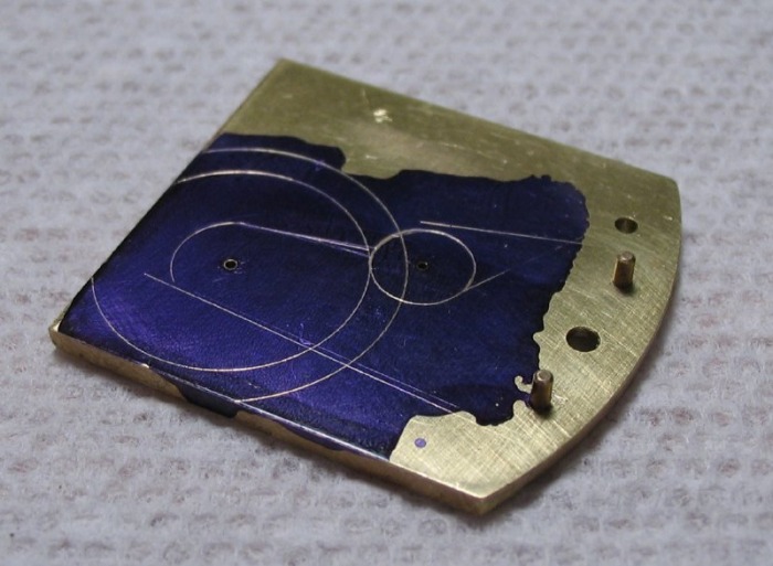
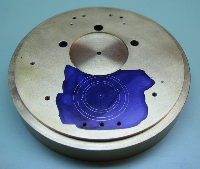
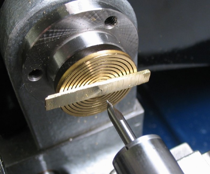
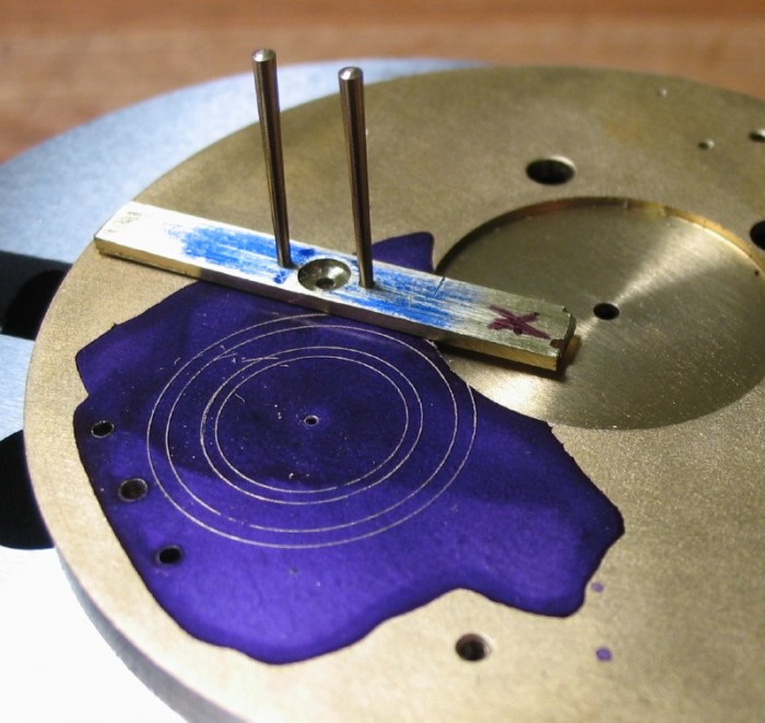
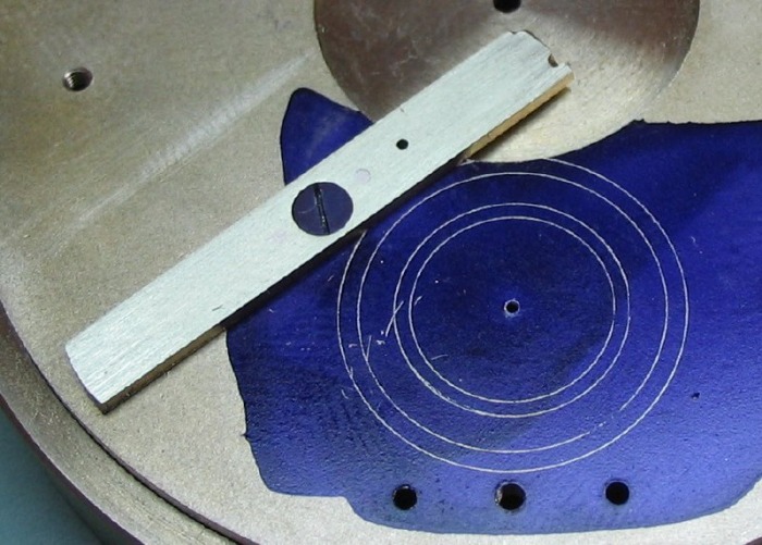
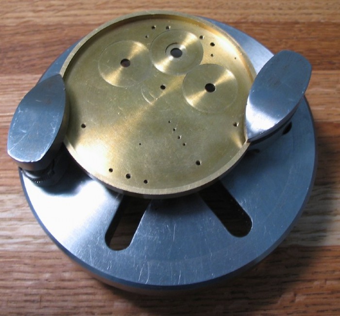
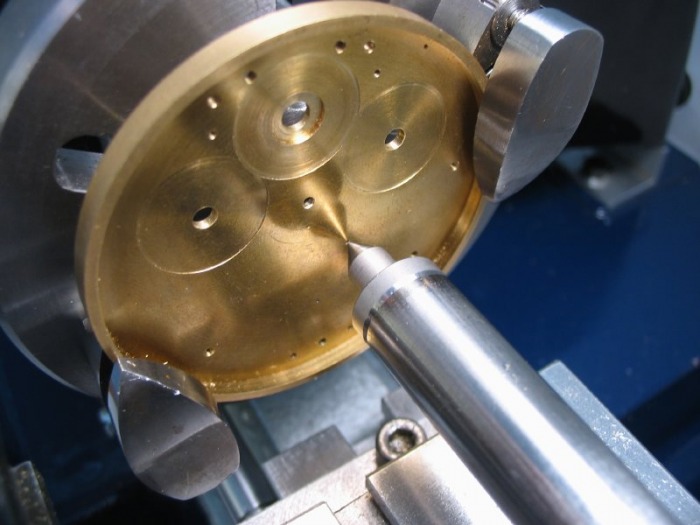
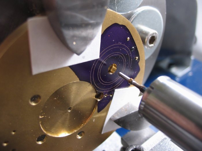
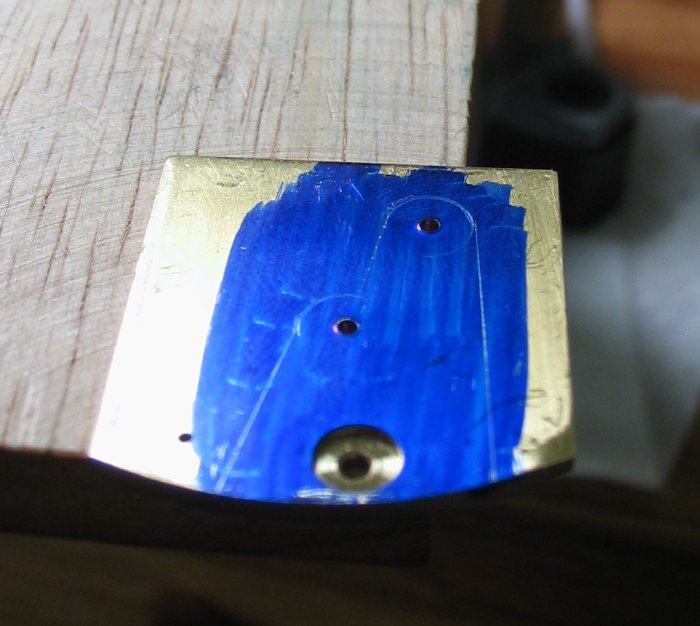
The potence plate is then coated in Dykem blue, and the recess circles scribed. I also decided to roughly sketch out the outline for the finished potence.
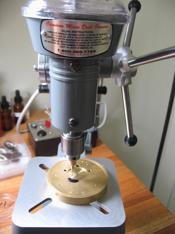
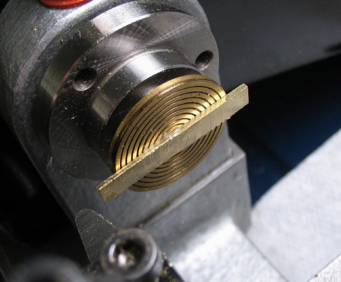
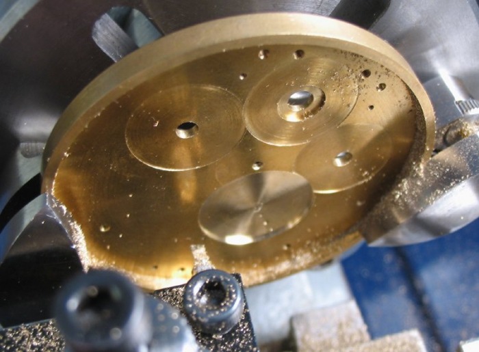
The plate can then be setup in the lathe on the faceplate, and the recesses bored out. The third wheel circle is bored to a depth of 0.7mm, and the carriage pinion circle to 0.9mm. A note to Daniels book, the drawing of the potence plate in figure 541 (first edition) is a mirror image of what it should look like. A minor error, it is what the plate looks like from above, but since it is drawn to show the recess boring process, it should be the reverse.
 |
 |
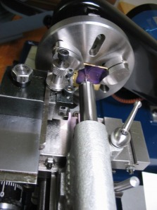
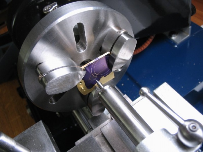 Centering the plate |
 |

Third Wheel Cock
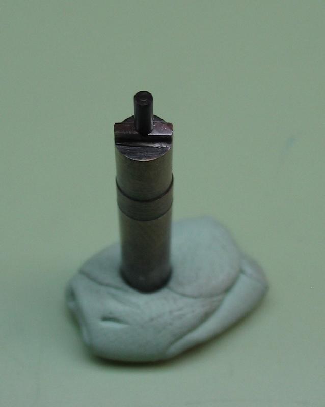
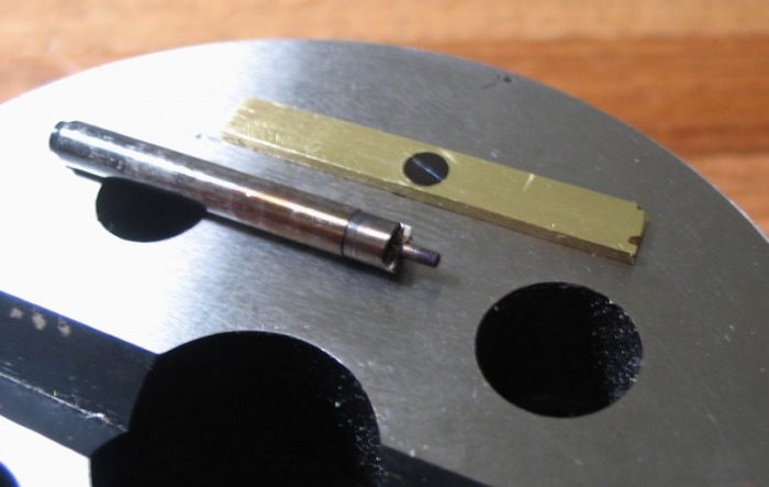
The screw was made from 3mm O-1 drill rod, the head is 0.5mm thick, and has 1mm diameter threads. It was hardened and tempered blue, shown below with the polished potence screw.
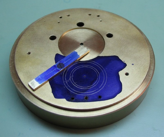
To determine the location for the cock, the dimensions of the fourth wheel recess and the recess for the escape potence must be laid out. The cock will be located tangentially.
 |
 |
| Third and Fourth Wheel Layout |
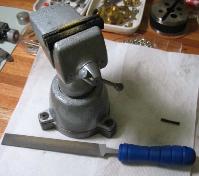
The blank is sawn out from brass plate using the table saw attachment. It was cleaned up with a No.2 Hand file to bring it to the desired dimensions.
 |
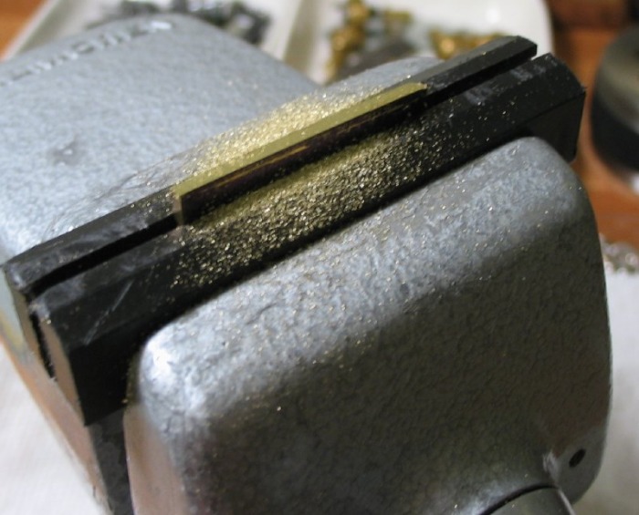 |
Since 1/16th inch plate is about 0.58mm too thick, the strip needed to be reduced. I decided to file one side flat and mount the blank onto a super glue chuck. The strip could then be faced down to size (1.0mm). While mounted I drilled to clear the screw (1.0mm) and counterbored to accept the screw head. This is the same counterbore made and used for the ratchet wheel bridge. I did not photograph the drilling and counterboring.

The mainplate is then drilled (0.80mm) and tapped 1.0mm. The plate is resting on the sacrificial drilling base. The cock blank can then be screwed to the mainplate.

Then, using the same procedure as described above for the potence, steady pins are made from taper pins and fit to the cock blank and mainplate.

Then drill through third wheel hole in mainplate into the cock blank. This hole can then be used to bore the recess in the cock to clear the third pinion. The boring is 0.75mm deep and ~3.0mm in diameter (2.9025 + 0.1).
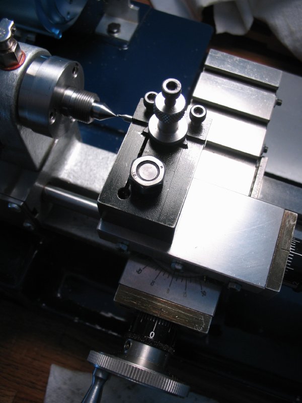 Set cross slide to zero using a headstock center |
 Morse taper center is ejected with a dowel |
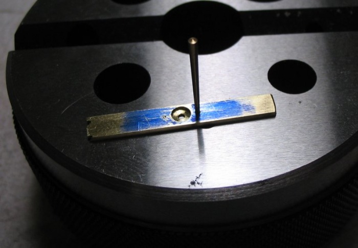
 Center cock blank on third wheel hole |
 Close up |
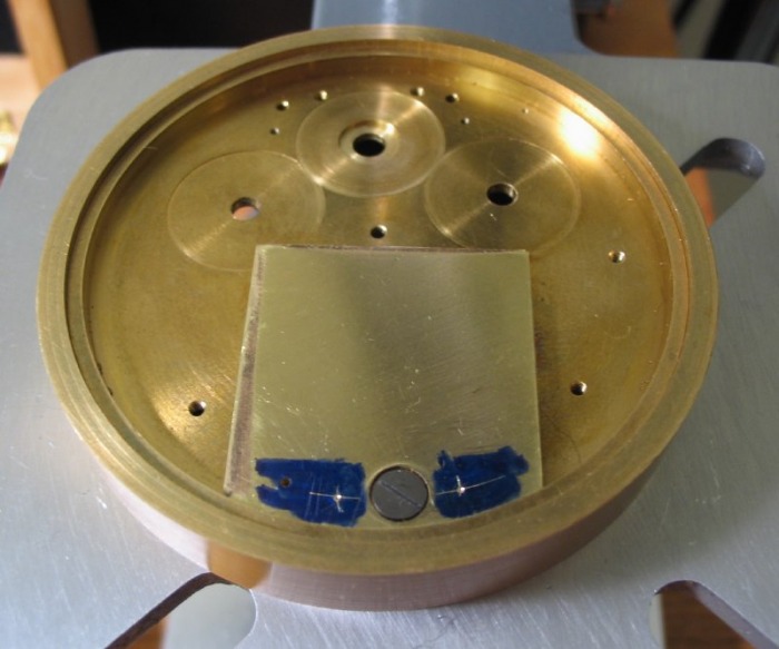
The mainplate is then setup on the faceplate to bore the third wheel recess into the dial side. The boring is to a depth of 0.55mm. I scribed a light circle as a reference and was momentarily flustered when I seen that it intersected with one of the ratchet wheel recesses. Upon looking at one of my movement drawings and thinking about it for a moment, all was well again, the third wheel resides under the ratchet wheel. Just thought I would mention it as a note, since one (at least I) will often experience moments of great joy, great defeat, and other times great relief in the watchmaking process...

Boring third wheel holes concentric
A. Fit lower potence to mainplate, and mount mainplate onto faceplate on lathe. Center, from the top, on the third wheel hole using the wobble stick to ensure accuracy.
B. Enlarge third wheel hole in mainplate to accept a boring tool, and bore open to clear third pinion (2.9025mm + 0.30 clearance). [A bore gauge needed to be made].
C. Enlarge hole in potence plate to accept the boring tool, and bore to diameter of jewel minus 0.1mm (1.20 - 0.1 = 1.10mm). [Another bore gauge needed to be made].
D. Finish potence plate hole with the appropriate jewelling broach (1.18mm).
E. Mount cock and enlarge hole to accept boring tool, and bore to 1.1mm
F. Broach hole to fit jewel (1.18mm).


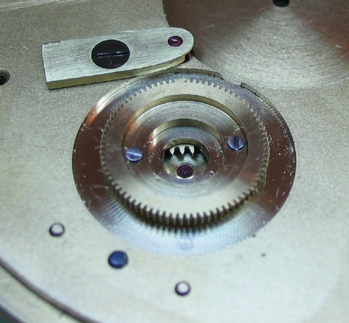
The mainplate is then centered on the carriage pinion hole using the wobble stick. The hole is drilled and bored to accept the carriage pinion collar (3.7mm). The jewel hole in the potence can then be bored and broached as well. This uses the same size jewel as the third wheel.
Note, while the plate is centered on the carriage pinion location, the location for the fixed fourth wheel is determined. For the details of this step I refer the reader to the fourth wheel page.
Finishing
The force of friction fitting the jewels may cause slight distortion to the shape of the plates, therefore Daniels recommends setting the jewels prior to cutting out the shape of the potence and cock.

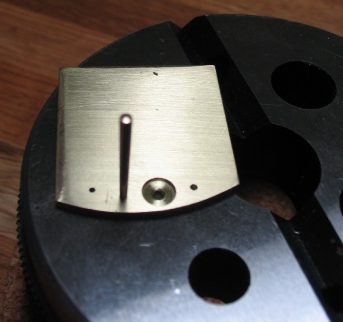
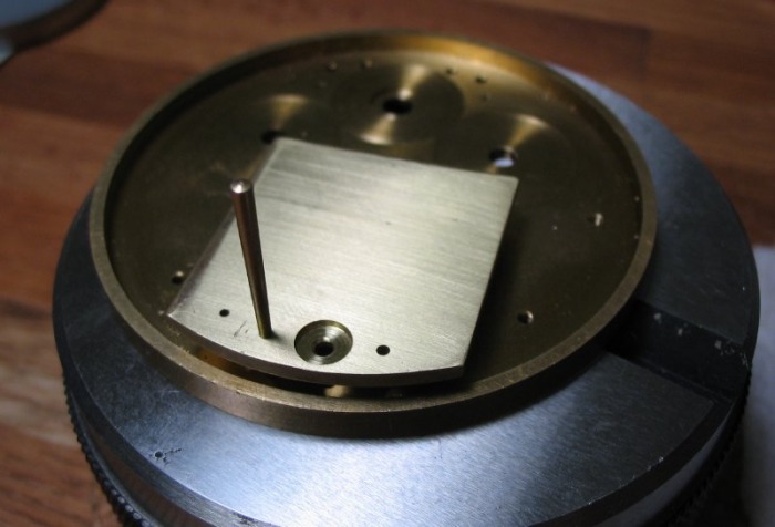
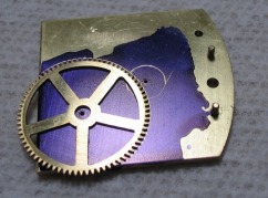
After setting the jewels, the final shapes of the potence and cock can be scribed, sawn and filed to shape.

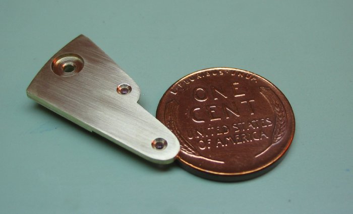


With the potence plates complete, and jewels set, the third pinion can now be completed. Goto third wheel page to read about that.
