An Auxiliary Motor
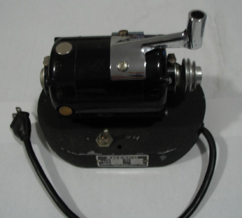
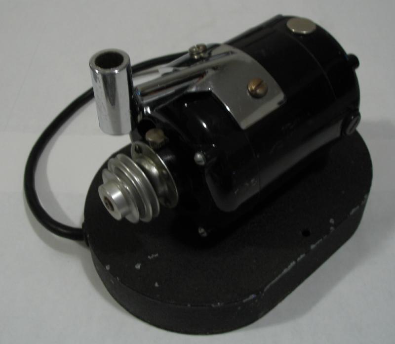
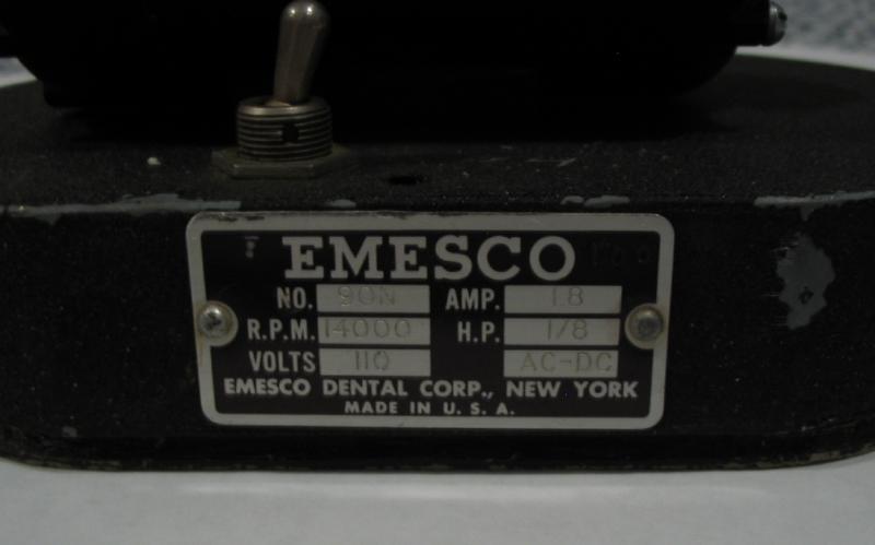
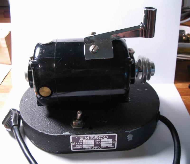
A spare motor was acquired primarily with the idea of powering the turns setup, however, it may find other uses around the workbench. A fairly old, Emesco Dental Corp., model 90N motor was found, and appeared to be in good working order, at least the carbon brushes were still in good condition. These motors were originally part of a setup intended for the dental industry. Although missing from this one, it would have an articulated arm with a series of pulleys for driving a dental drill handpiece. The mount for the arm is all that remains on this particular unit, and my initial intention was to use it for mounting a support arm and idler pulley. The Emesco model 90N uses a 14,000 RPM, 1/8 HP, reversible, AC motor. These units are still manufactured, with some changes, by the Buffalo Dental Manufacturing Co. (see catalog page below).
| Buffalo No. 16 Bench Engine | |
| File Size: | 401 kb |
| File Type: | |
The unit as it was received
.
Speed Controller
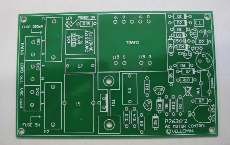
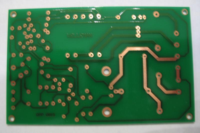
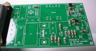
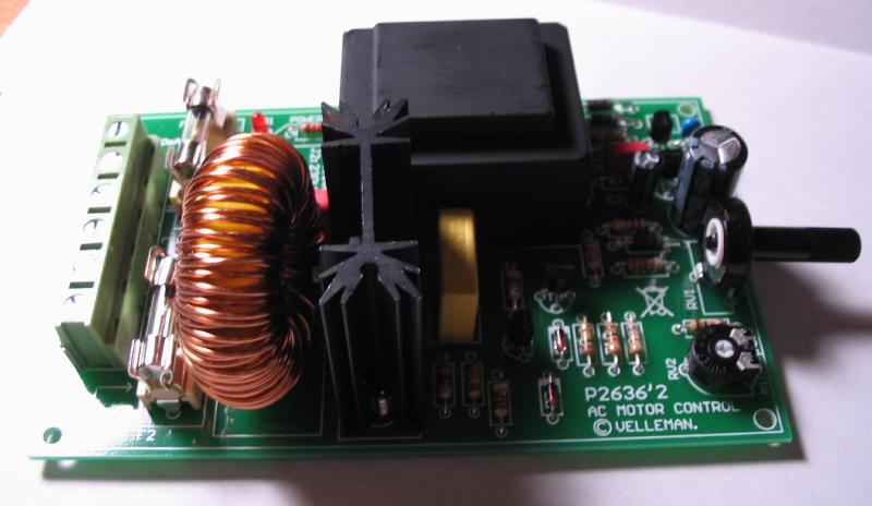
To reduce the speed of the Emesco motor an electronic speed controller was constructed. This project was started with a Velleman K2636 electronics kit which is a thyristor based circuit. The parts list, schematics, and assembly instructions are provided below. The intent was to find a way to reduce speed without a large loss in torque. The manufacturer states that the circuit reduces motor speed by phase cutting. The moment of cutting (5 to 95%) determines the resulting speed of the motor. Much more detailed information and explanations of phase control circuits can be found elsewhere.
| Assembly Manual - Velleman K2636 | |
| File Size: | 1734 kb |
| File Type: | |
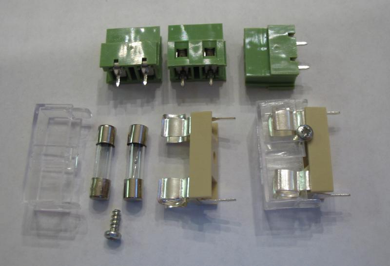
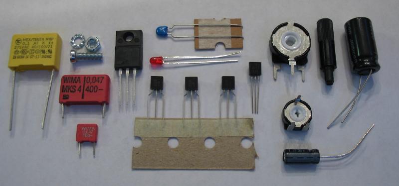
The parts were photographed as they were taken out of the package to double check the correct inventory.
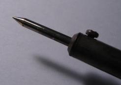
Following the prescribed order in the manual, the components were attached to the PCB and soldered in place. I used a rather old soldering iron, but cleaned the tip with a slip stone prior to use to remove the build up from previous tasks. The tip of the iron should be kept clean with a wet sponge during use to keep the solder flowing well.
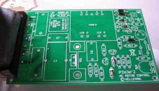
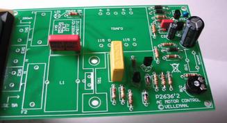
The PCB was held in a small vise with nylon jaws. The adjustable vice allows the board to be easily flipped over to insert a component and then solder it in place. I installed one component at a time to avoid any mistakes. First the diodes were installed, paying close attention to their polarities.
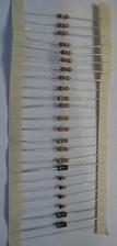
The resistors were installed next. Velleman conveniently supplies the components taped together in order of installation. Resistors were checked individually with an Ohm meter to assure they were correct. Alternatively, the color code of each resistor can be looked up in the included table to double check it's resistance value.
| Resistor Color Code Chart | |
| File Size: | 322 kb |
| File Type: | |
The capacitors and transistors were installed next.
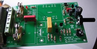
The power components and potentiometer.
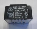
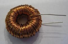
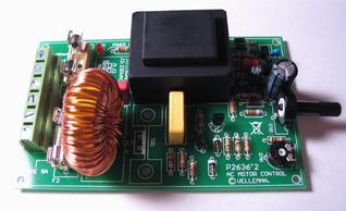
The transformer and inductor coil.
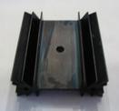
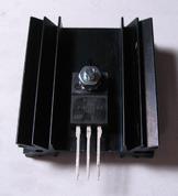
Finally, the TRIAC was attached to its heatsink which is screwed to the PCB and then the component soldered in place.
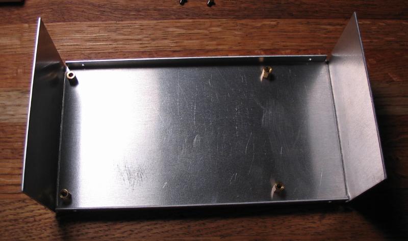
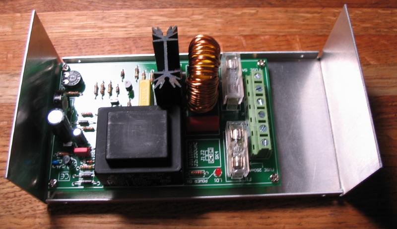
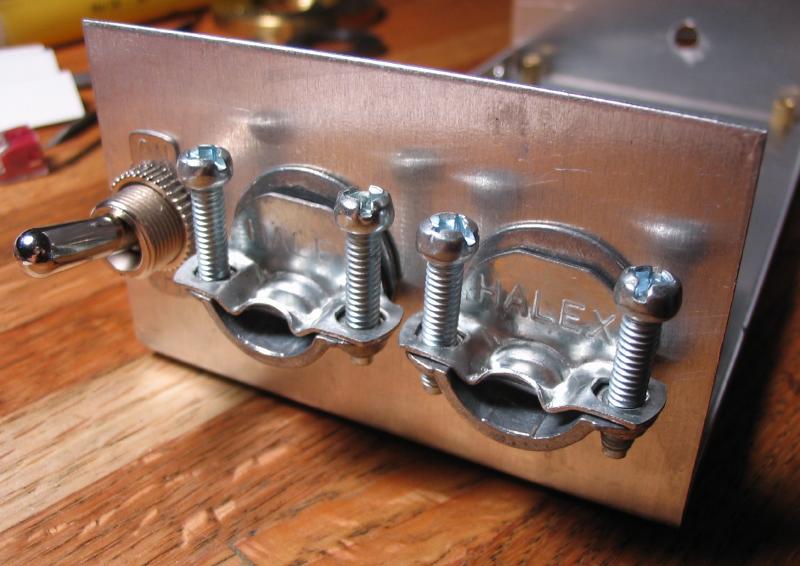
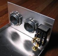
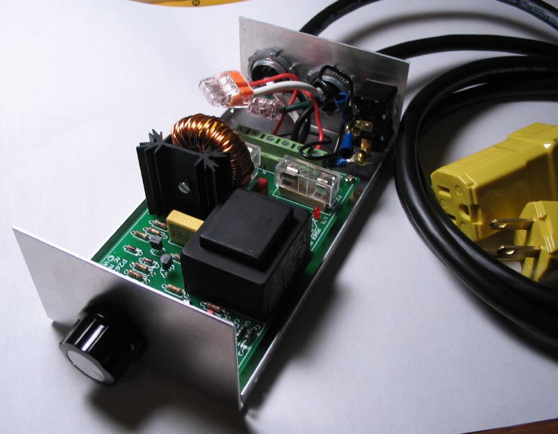
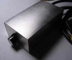
A suitable sized enclosure for the circuit board took some searching to find. I settled on an aluminum, LMB/Heeger "Crown-Royal" (CR-632), which provides ample space for the board and wiring. Positions for standoffs and a hole for the potentiometer shaft were drilled. Hex Brass standoffs (M3 - 5mm in length) were installed with matching M3 screws. The rear of the case was sawed and filed to provide openings for the input and output cable clamps and a main power switch. The cable clamps are household junction box clamps (Halex brand), and the switch is a simple, single pole, single throw toggle rated for 125V.
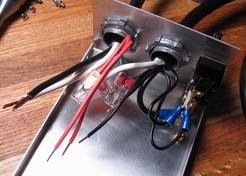
A power cord and a matching output cord were assembled from 14 gauge, 3-conductor cable. The ends were fitted with Hubbell Valise male and female plugs, respectively. The wiring was installed and jumpers made to connect the power supplying wires to the separate inputs of the circuit board. The Velleman K2636 has a main input to power the circuit itself and a separate input that ultimately powers the motor. The circuit can therefore be used with any voltage supply to match the motor. In this case, the same 110V-60Hz is supplied to both inputs. Neither the circuit nor the Emesco motor are grounded, however, three conductor wire was used and the ground wires connected directly from the supply line to the output. This way the speed controller can be used on another motor which is properly grounded.
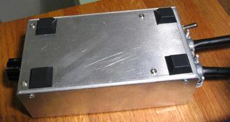
The motor was connected and powered up. The secondary potentiometer is adjusted so that when the main knob is turned all the way down, the motor is still moving. This is to prevent overloads, but this can also be reset later when the motor is under a typical load to provide a more usable minimum speed. The cover was installed, and four 3M brand "Bumpon" rubber feet (SJ-5023) adhered to the bottom, and it is ready to go.
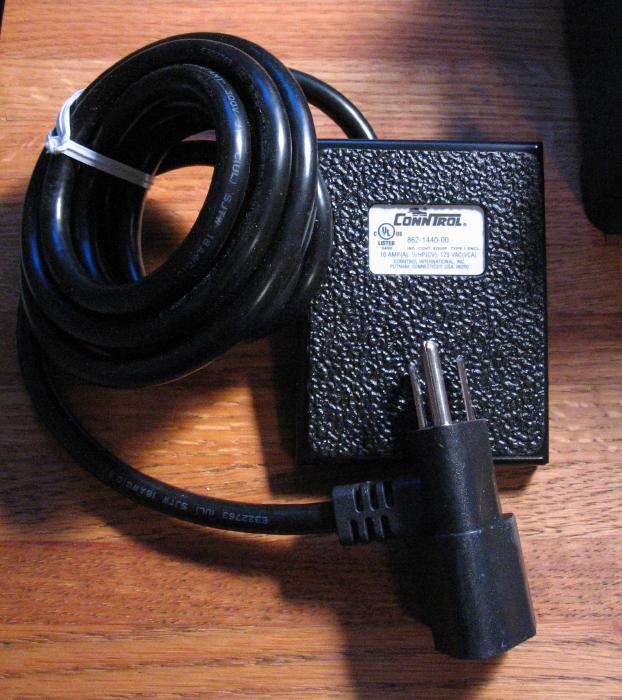
Although the speed controller has an on/off switch, the ability to switch the speed controller on and off while keeping ones hands on the work could be useful in some situations. A Conntrol brand momentary foot switch was added to the setup. When depressed it switches on and is turned off when released. It is rated for 125 volts AC at 10 amp. The switch connects by means of the power cord.
Countershaft
The motor is specified as 14,000 rpm, which is much too fast, so even with a speed controller, the upper range is not useful. A countershaft pulley setup was constructed to reduce the top speed. A ratio of 3.5 : 1 would reduce the top speed to about 4,000 rpm. This will be accomplished using a 4" pulley that is driven by one of the two pulleys on the motor itself (29 and 32mm in diameter).
Main Pulley
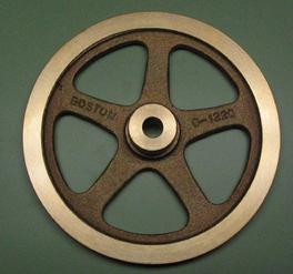
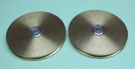
The pulley shown is made by Boston Gear and is a 4 inch diameter brass wheel with a 5/16" bore and has a vee for small round belts (>1/8").
The pulley shown is made by Boston Gear and is a 4 inch diameter brass wheel with a 5/16" bore and has a vee for small round belts (>1/8").
| Boston Gear - G1200 Series | |
| File Size: | 68 kb |
| File Type: | |
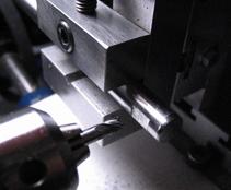
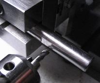
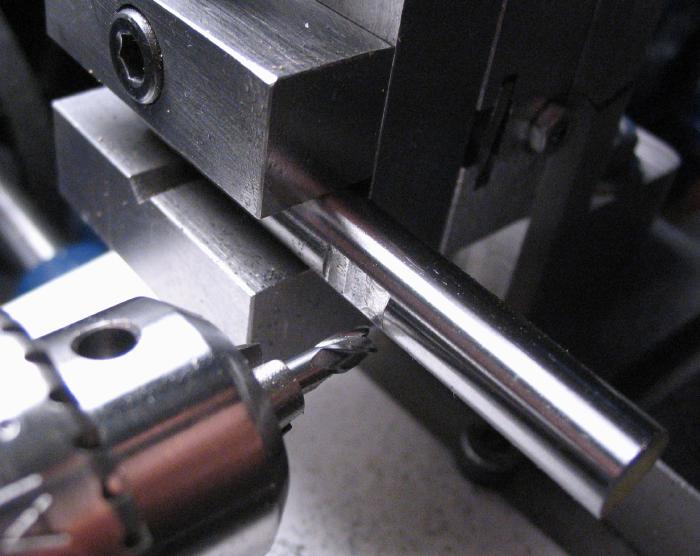
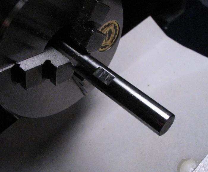
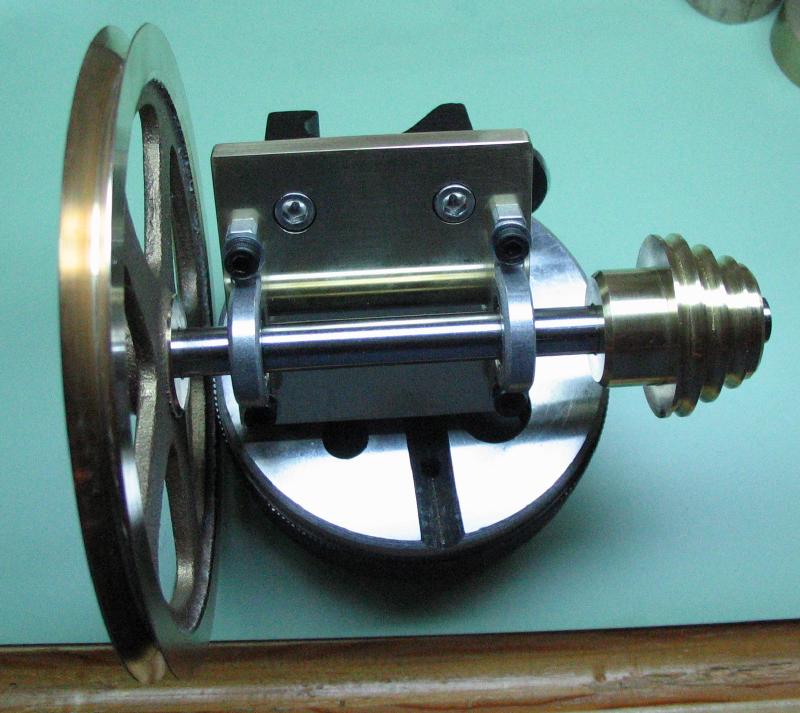
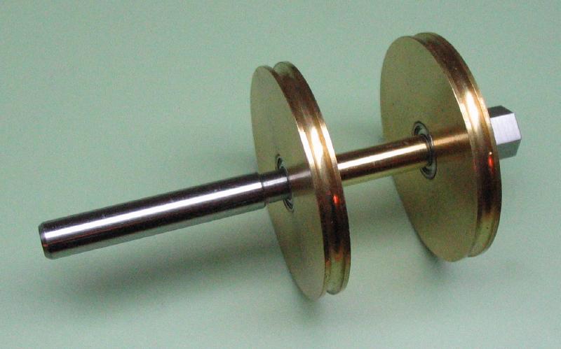
The pulleys will be attached to a 5/16" shaft made from a length of drill rod. The rod is sawed off and the ends chamfered with a file. The rod was polished with 400 and 600 grit emery paper to pass, with a very snug fit, in the pulley and especially the bearings. Two flats are milled at the positions for the securing screws in each of the pulleys.
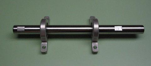
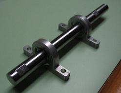
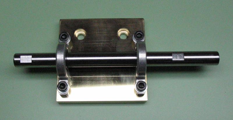
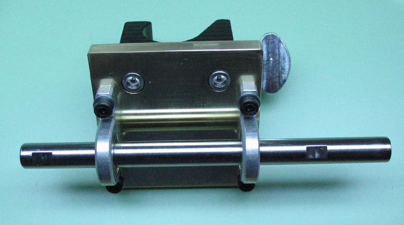
The shaft is inserted into ball bearings which are already mounted in housings. The ball bearings will be then mounted onto a support plate. The pre-mounted ball bearings shown here are Spyraflo (PB0-SRW1810ZZS) bearings mounted in aluminum frames.
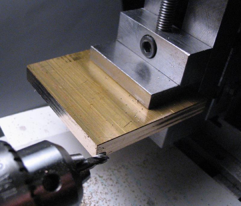
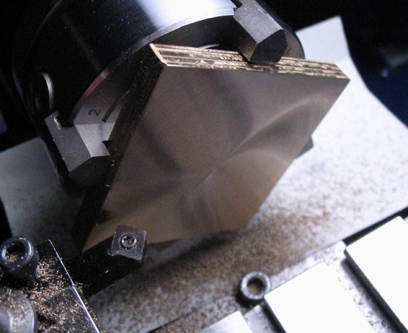
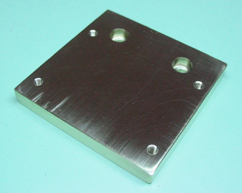
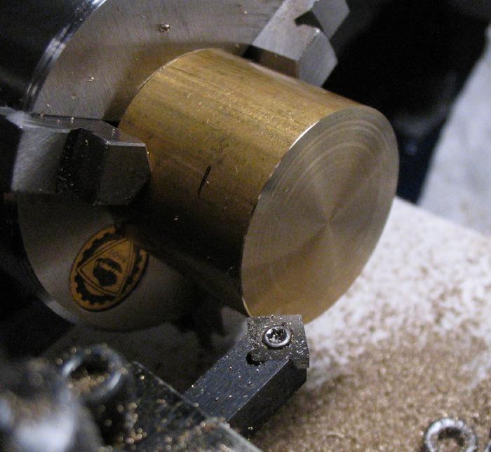
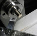
The mounting plate was made from a 2 inch square of 1/4" thick brass plate. It was milled around the periphery to remove saw marks and square the dimensions, and it was then faced on both sides while holding in the four-jaw chuck.
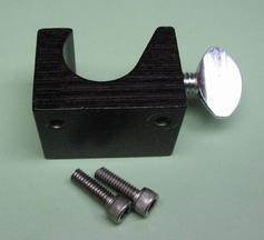
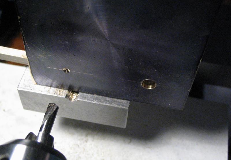
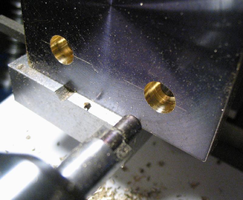
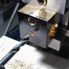
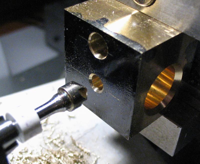
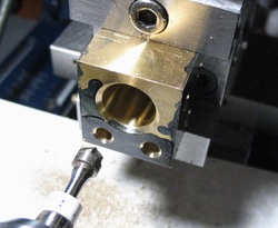
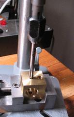
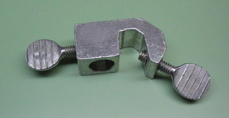
The plate will attach to a rod by means of a clamp. I decided to use a clamp made by Troemner (No. 916134) and is referred to as a "universal stirrer mounting bracket." These are intended for laboratory use and designed to mount on 1/2" rods used on laboratory stands. The clamp has two screw hole positions, 1 inch apart, that are threaded #8-32. Two 4.2mm holes were drilled in the plate and then counterbored 7mm to fit #8-32 socket head screws. A counterbore needed to be made, and the details were posted on the counterbore page.
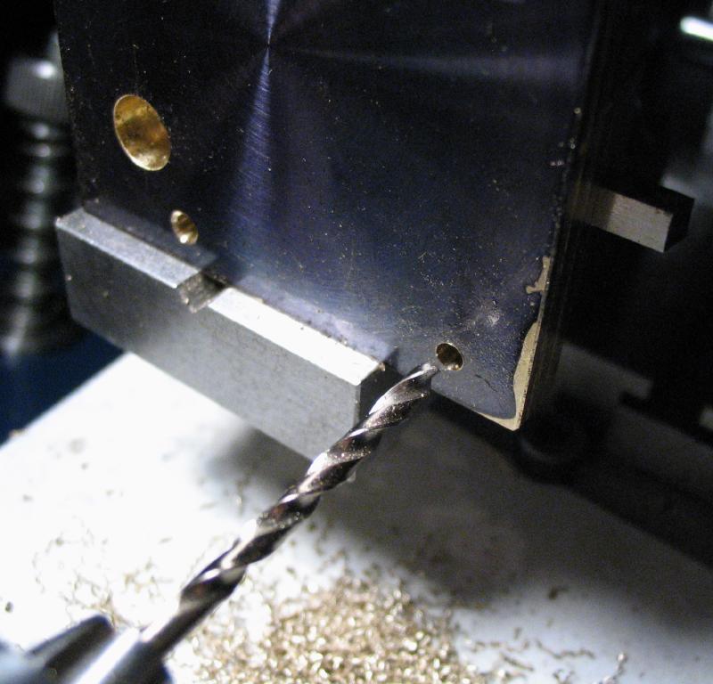
The plate was then drilled 2.5mm and tapped M3x0.5 in four positions to mount the Spyraflo bearing mounts above.
The bearing mounts are attached to the plate with four 3mm socket head screws and washers. Likewise, the plate is attached to the clamp with the 8-32 socket head screws.
Drive Pulley
| Countershaft Pulley | |
| File Size: | 1158 kb |
| File Type: | |
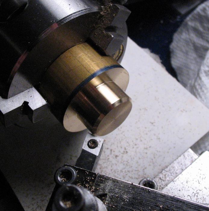
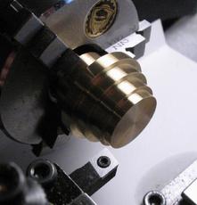
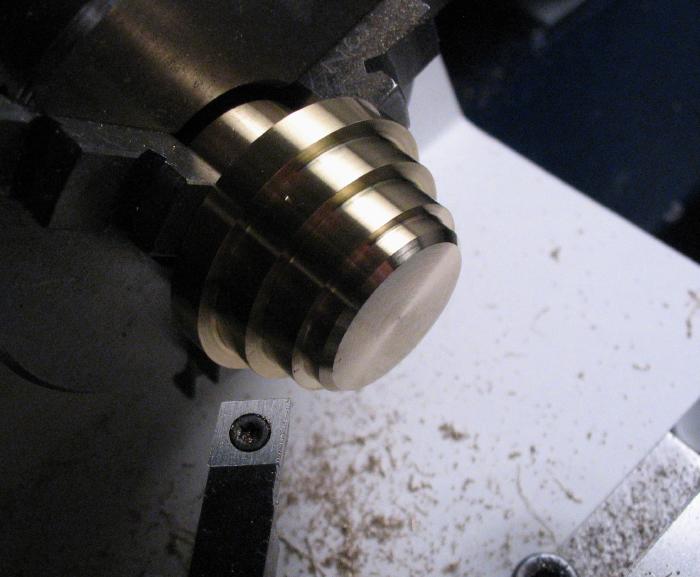
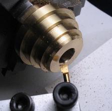
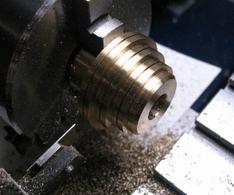
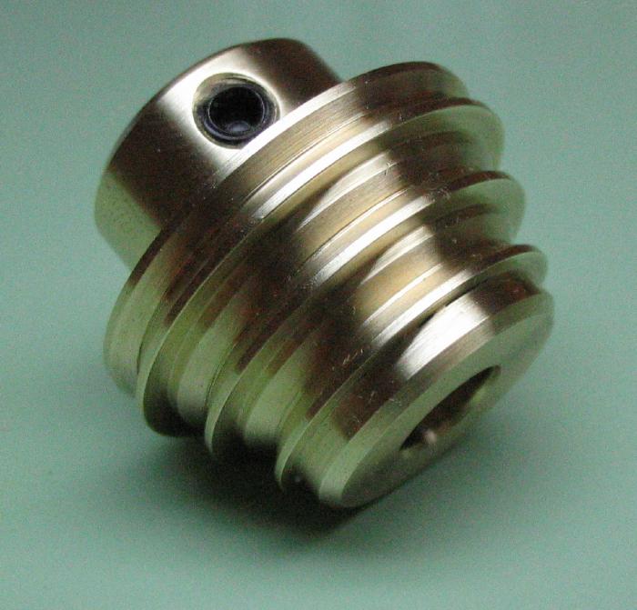
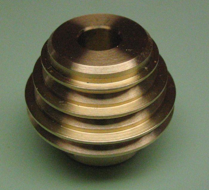
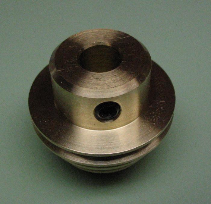
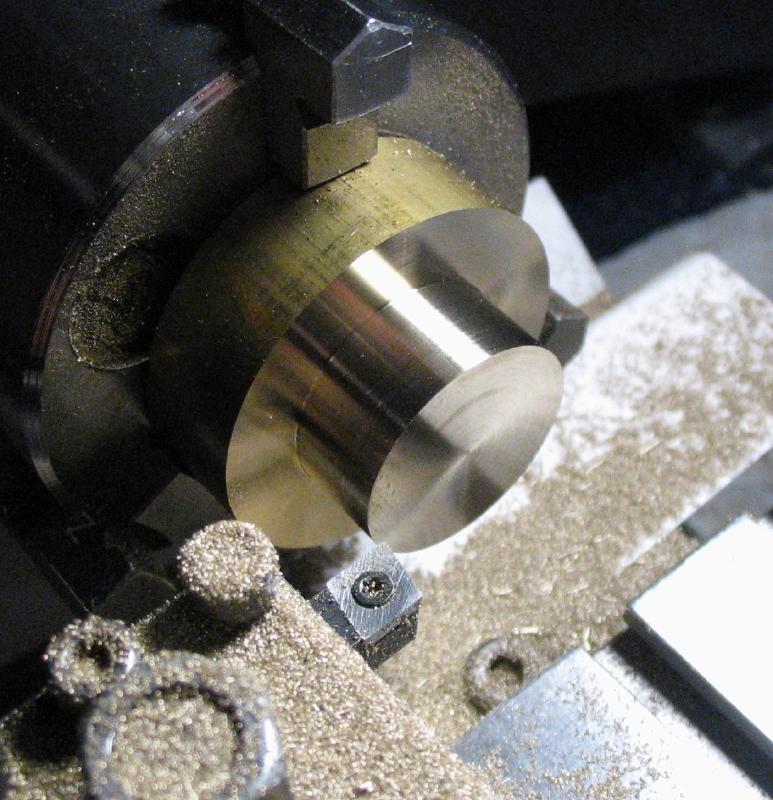
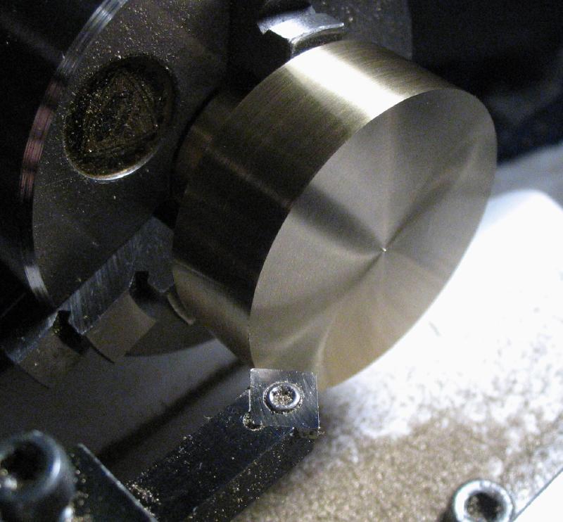
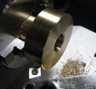
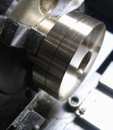
The smaller pulley is made from 1.25" brass rod. A section of about 1 inch is setup in the 3-jaw chuck and faced on both sides. It can then be turned to about 3/4" in diameter for about 10mm. The corner was chamfered 45 degrees.
The work is reversed in the chuck and secured on the turned portion.
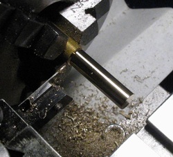
The diameters for the three pulley steps are turned first and the remainder turned to 3/4" and chamfered.
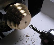
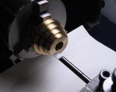
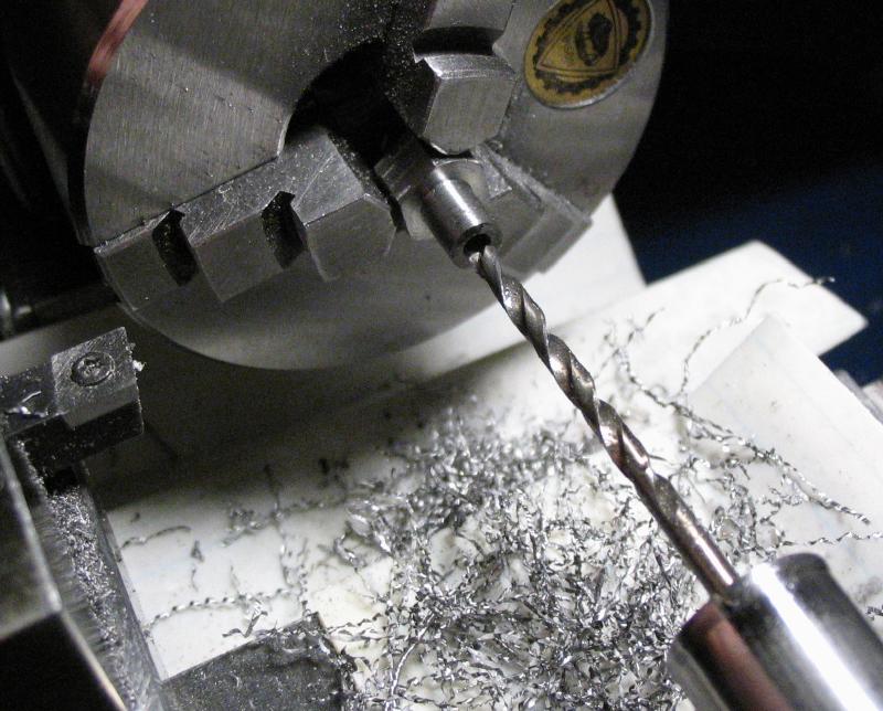
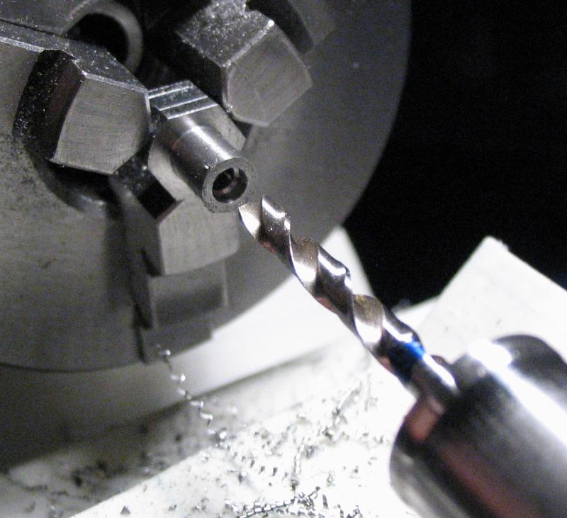
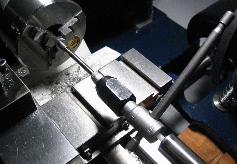
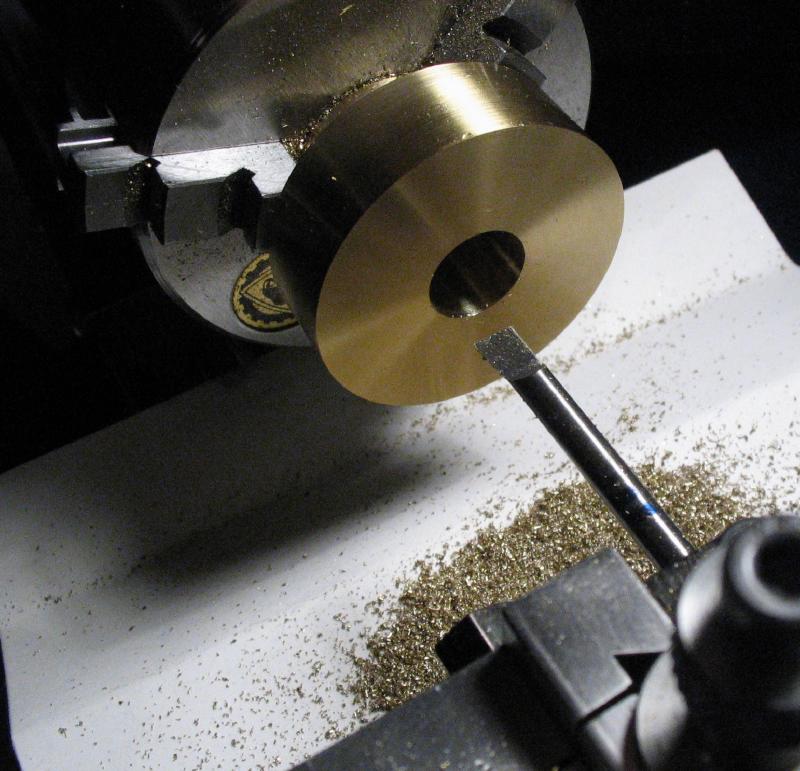
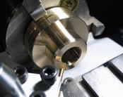
The work can now be drilled open to accept a boring bar, and then bored to pass the 5/16" shaft with a fairly tight fit. Boring undersize and reaming to final diameter would be preferred, but that size was not on hand.
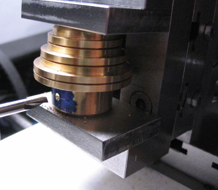
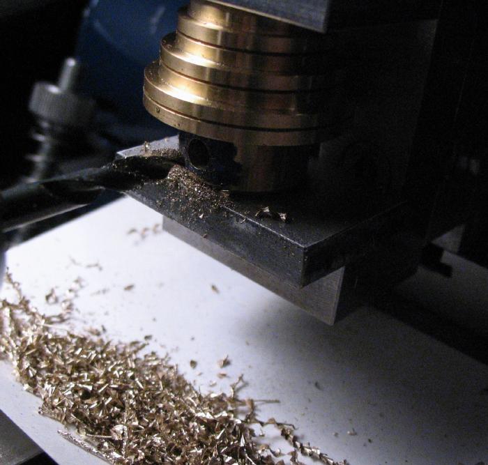
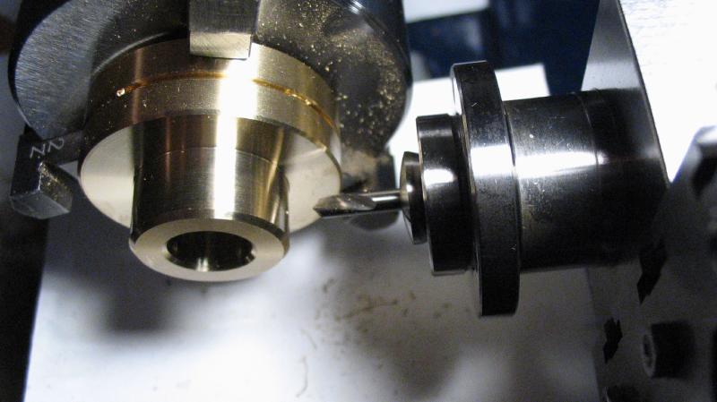
The center groove for each pulley was formed using a 1/64" cut-off bit. The groove was turned to a depth of 1.3mm in the center of each pulley diameter.
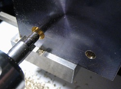
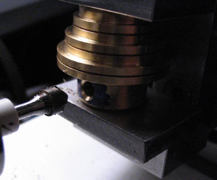
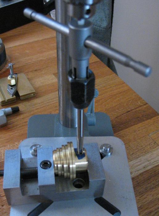
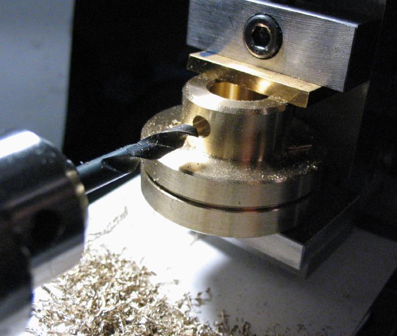
The pulley was transferred to the vice mounted on the vertical slide and the position for the set screw was drilled 4.2mm and then tapped M5x0.8, using the drill press for maintaining tap alignment.
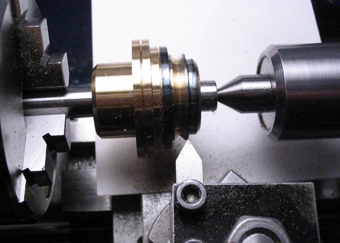
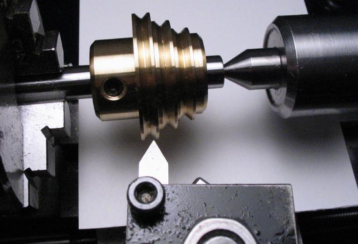
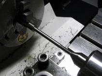
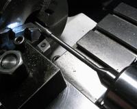
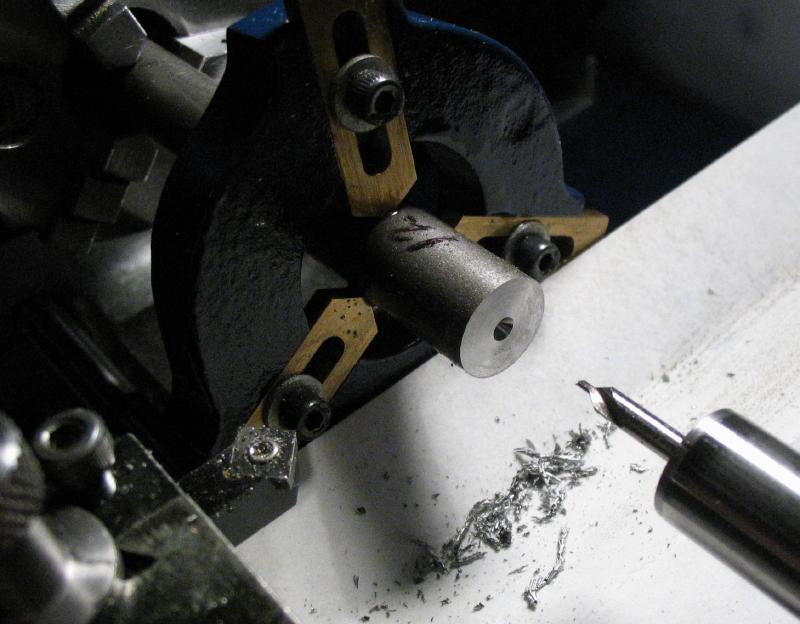
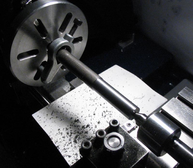
The pulley was mounted onto an arbor made from 5/16" drill rod. This allows for more clearance while turning the internal angles of the pulley diameters. The rod was milled for the set screw. The rod was mounted in the 3-jaw chuck and supported with the steady rest to face and center drill for tailstock support.
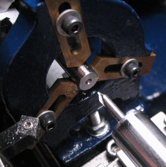
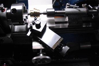
The pulley is then mounted to the arbor to turn the vee portions. Although not ideal, a 60 degree profile lathe tool bit was used and the topslide set to the respective 45 degree angles. Light cuts and the free machining brass allowed for turning the vees without much trouble.
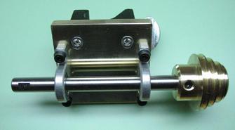
The pulley can be added to the shaft and bearing setup, along with the 4 inch Boston gear.
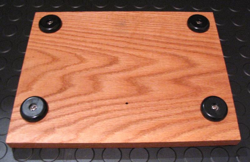
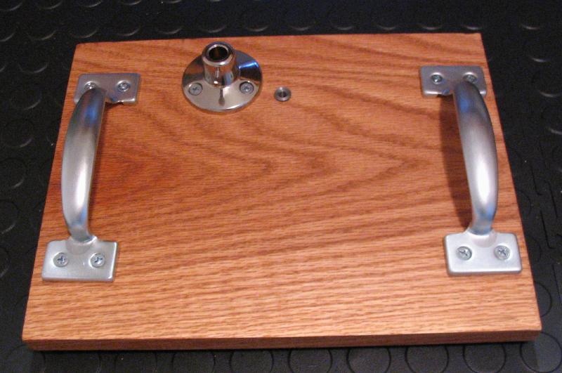
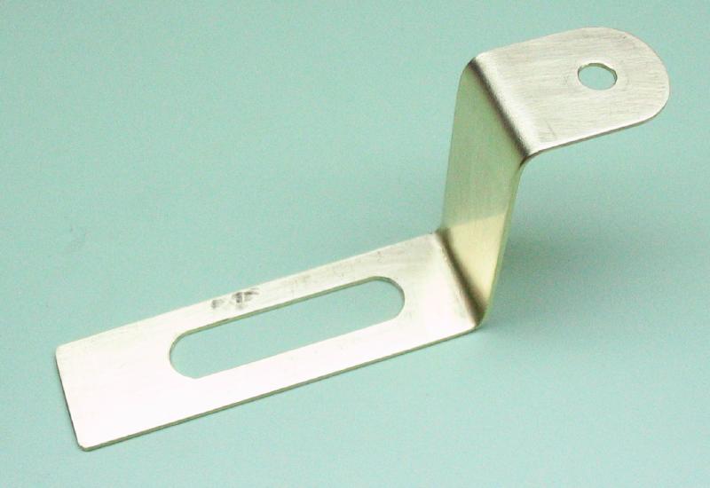
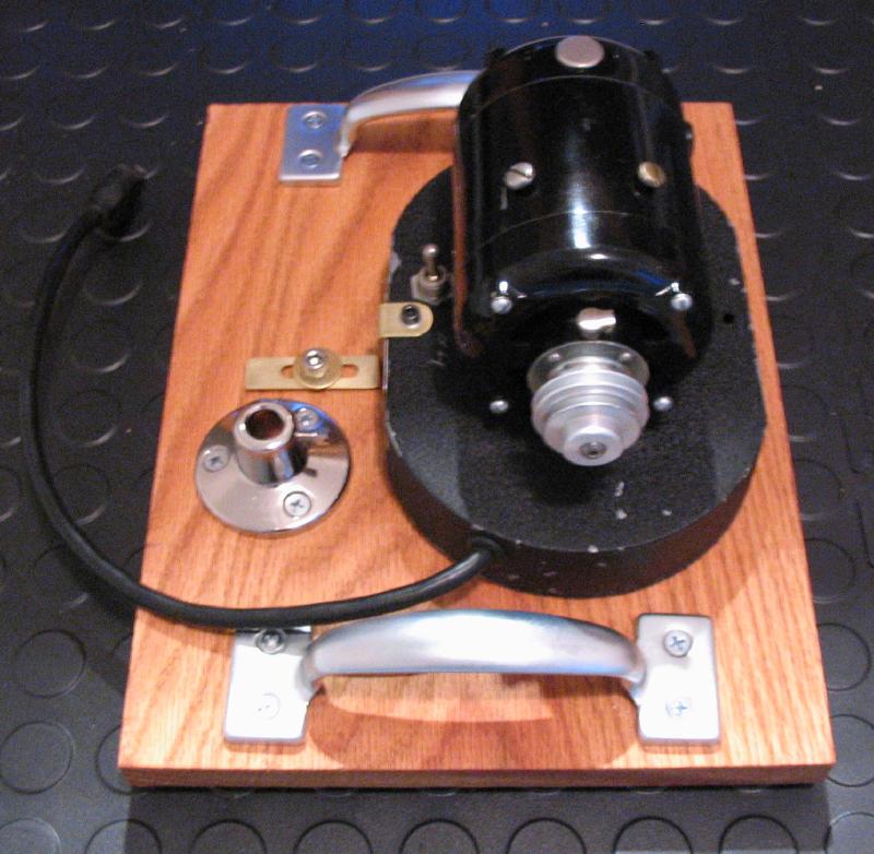
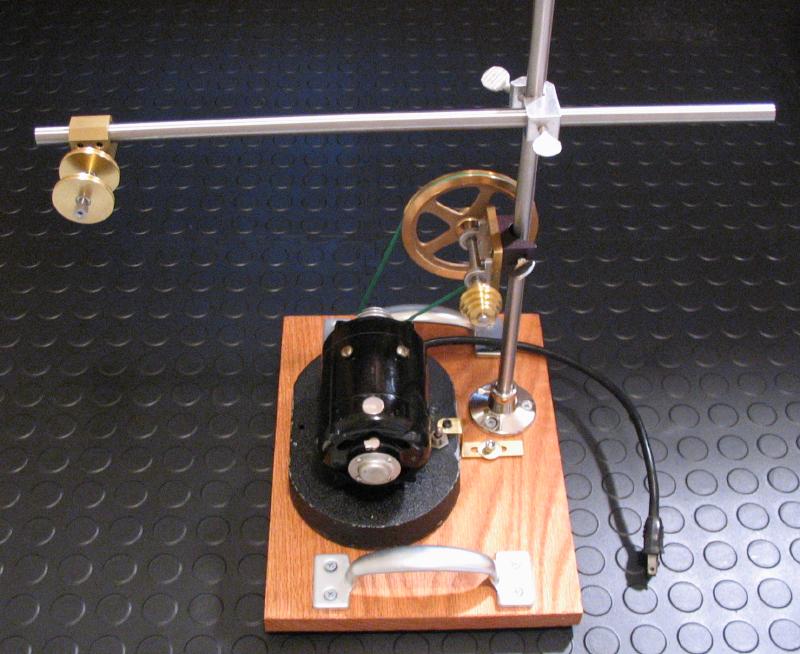
A odd piece of oak board about 1 foot square and 1/2" thick was rubbed with oil, given some feet, and a Troemner No. 916132 lab-frame foot attached to the top. The motor itself is weighted, however, a bracket was constructed from brass plate to help secure it to the wood base. A 1/4"-20 threaded insert was fixed into the oak base to lock the bracket in position. The bracket is slotted to allow for flexibility in the motor's position. A pair of handles were attached to the base to allow for easy moving.
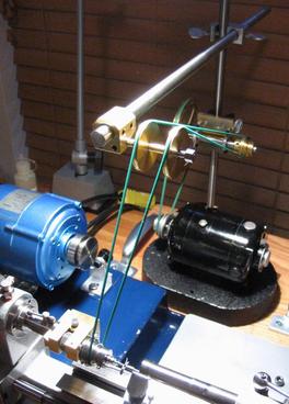
The frame foot accepts 1/2" rod. The pulley assembly is mounted on a length of 1/2" drill rod and secured in the frame foot. A length of 3mm polycord is fit to the drive pulley of the motor and the 4 inch Boston Gear pulley. The polycord was purchased without manufacturer information, but should be comparable to Habasit. It is cut to length and fused by heating a blade and touching the adjoining ends to melt the cord and join together. Afterward the excess can be trimmed to provide a smooth transition.
Idler Pulley
The small pulley will drive the intended work by means of a separate belt. The advantage of the polycord is that it can be fed in an indirect fashion, and in this case, a set of idler pulleys will be used to help increase belt tension while directing the belt to the desired location. The pulleys simply provide a freely rotating surface to minimize frictional loss. An arm made of 1/2" drill rod is mounted to the previous 1/2" post using a 90 degree adapter. This one is old stock, but various versions are available from Troemner or one can be made, of course. An adapter was made that attaches to this arm to provide a means of mounting the idler pulleys.
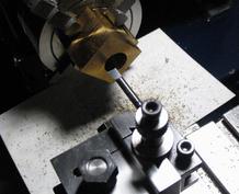
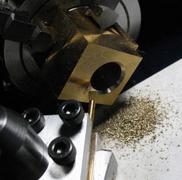
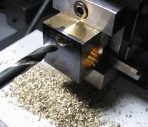
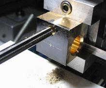
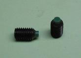
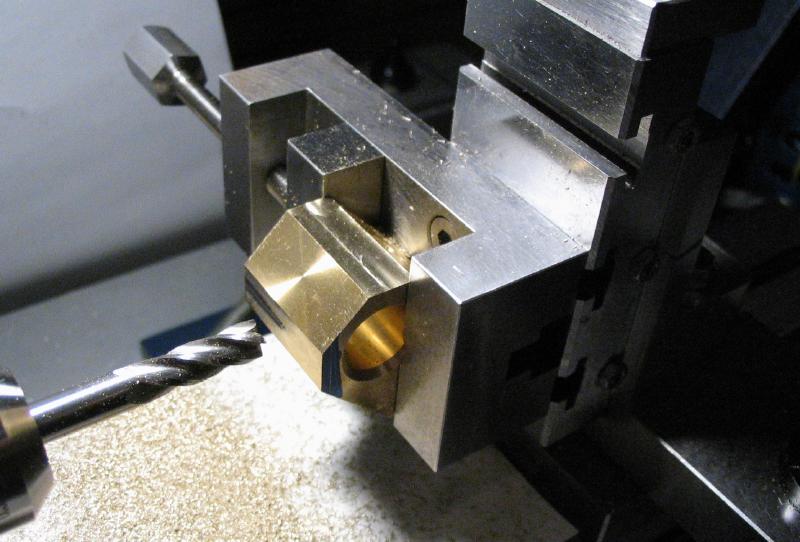
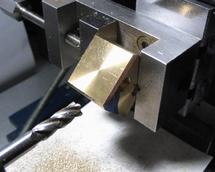
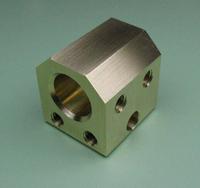
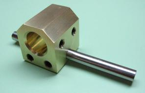
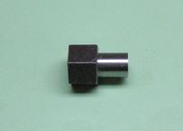
The adapter was made from a piece of roughly 1" square brass that was about 3/4" in length. After facing on each side using the 4-jaw chuck, the block was drilled and bored open to accept the 1/2" drill rod. The opening was countersunk on each side as well using a small boring bar and the compound topslide. The block was then transferred to the machine vise and vertical slide to drill and ream 6mm to accept a length of 6mm drill rod that will form the axle of the idler pulleys. Positions for M5x0.8 set screws were drilled and subsequently tapped. Lastly, the block was milled on various corners simply to make it somewhat more aesthetically pleasing. I happen to be using stock set screws with nylon tips that provide a better grip on round shafts. These screws are available through Buckley QC fasteners.
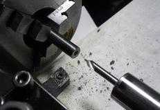
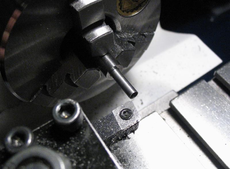
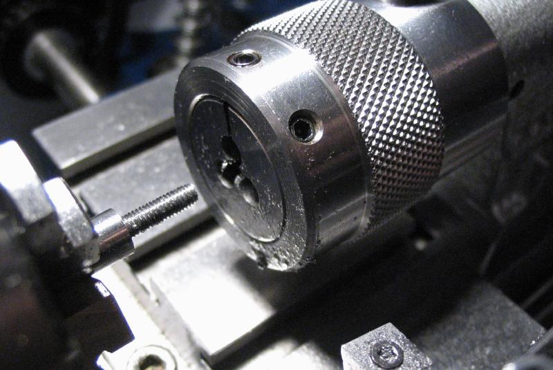
The 6mm drill rod shaft above was faced on either end and chamfered, one end is center drilled and turned down to 3mm for about 10mm. This diameter is then threaded M3x0.5 with a die. The center cone was touched up with the center drill and the shaft extended to turn down to 1/8" for about 28mm in length. A small shoulder was turned down to 5mm to match the pulley ball bearing hub.
A spacer was made from 1/4" brass. It was faced, turned to about 5.5mm and a 20mm piece parted off. The parted section was transferred to a collet and faced, chamfered, drilled 3mm, reamed 1/8", and finally countersunk on each end.
Although the pulley bearing are a snug fit on the axle, the axle is threaded on the end and a securing nut was made. A 3/8" diameter piece of 12L14 mild steel was turned to about 9.2mm and the headstock then locked. The milling spindle and 1/8" endmill was used to mill six flats to form a hexagon with a final width of 8mm and length of about 6mm. The work was parted off at about 12mm in total length.
The work is reversed in the 3-jaw chuck and turned down to about 5mm to match the bearing hub, drilled 2.5mm, counter drilled 1/8" for a short length to pass the bearing axle, and then tapped M3x0.5. The work was reversed once again and countersunk. The flats were then polished on emery paper to remove milling marks.
The pulleys used as idlers are made by Dynaroll (model BPGP3-48). The ball bearings have a bore of 1/8" and the pulley diameter is 1.5", width is 5/32", and are designed for a belt diameter of 3/32".
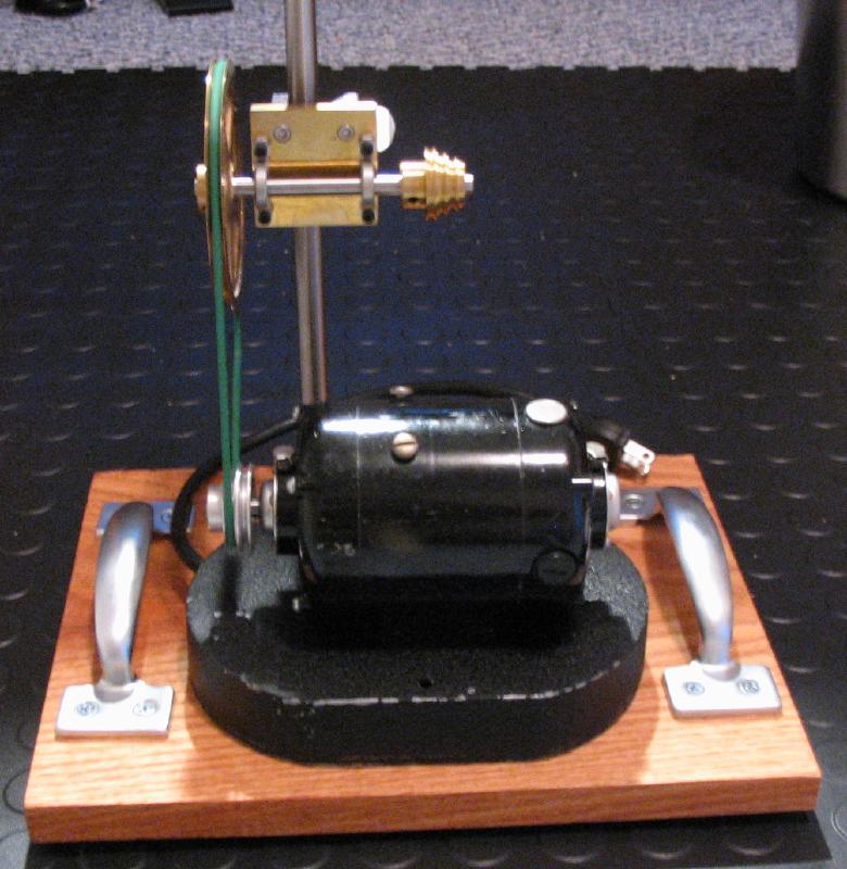
The final arrangement of parts.
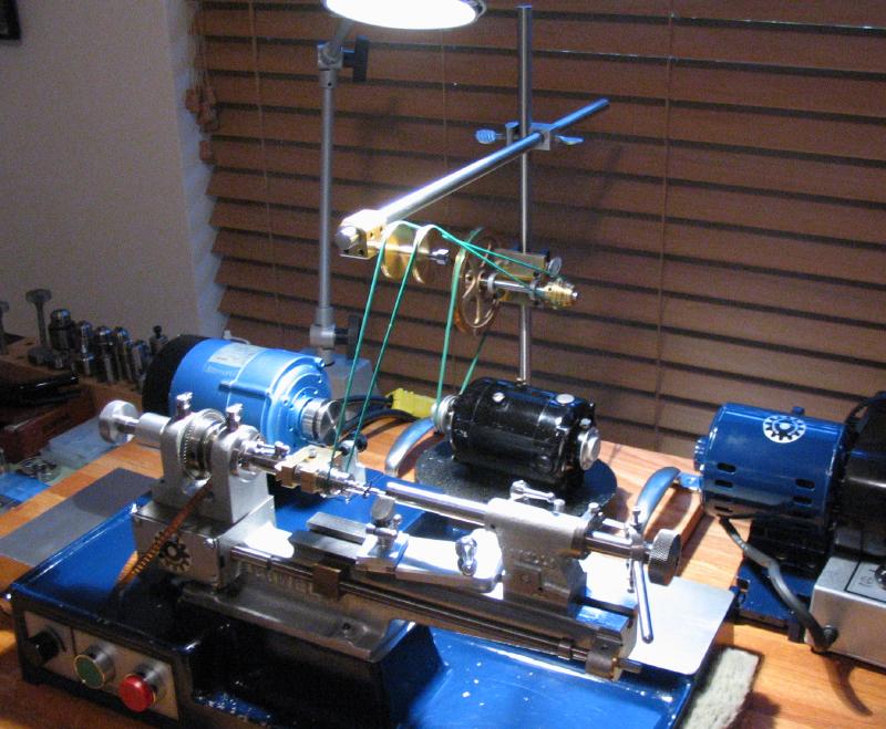
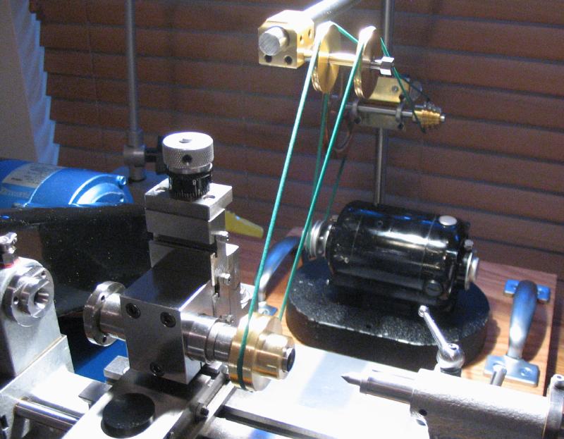
The motor and assembly was set up on the bench behind the Cowells lathe. Here are some photos of the motor setup for use in powering the turns headstock pulley. The drive pulley and headstock are powered with 2mm Habasit polycord which was cut to length and joined together.
Milling Spindle Pulley
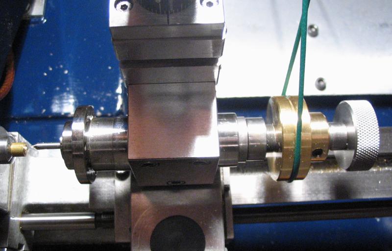
Another intended use for this auxiliary motor is for powering the Cowells milling spindle when set up on the lathe parallel to the headstock axis. The standard drive supplied by Cowells only allows for the spindle to be driven when mounted perpendicular to the headstock (for wheel cutting, etc.) However, the ability to set up the spindle parallel would allow for certain drilling and milling jobs.
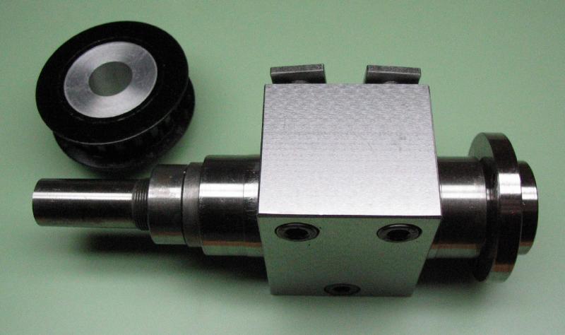
Since the spindle is supplied with a toothed pulley, a replacement pulley is needed that will accept the polycord drive belting. One such pulley is described below. The work was started from a length of 1.5" diameter brass rod (type 360) which was mounted in the 3-jaw chuck (jaws reversed), faced on either end, and then turned down to about 23mm for a length of about 10mm. The work could then be reversed in the chuck and the diameter turned true and then drilled and bored to fit the milling spindle (mine measures 11.74mm). The hole was then counterbored.
| Alternative pulley for Cowells milling spindle | |
| File Size: | 933 kb |
| File Type: | |
While still mounted in the chuck the corner was lightly chamfered and then the pulley groove was started using a 1/64" width parting tool to a depth of 1.5mm. I started to turn the vee-sides of the groove as well, but found there was insufficient clearance between the chuck and toolpost, so the groove will be finished last by mounting on an arbor.
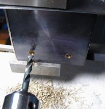
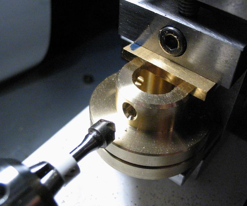
The work can now be reversed once again to turn the boss down to its final diameter of 22mm. The bore was then counterbored and corners chamfered on this end as well. Using the milling spindle, two positions were spot drilled at 90 degrees to one another. There was not enough clearance for the 4.2mm drill, so the work was transferred to the machine vise on the vertical slide. The spot marks were used to align on center, drilled 4.2mm, countersunk, and subsequently tapped M5x0.8. These positions will accept the M5 x 5mm set screws to lock the pulley onto the spindle.
In order to finish the pulley groove, an arbor was prepared for mounting the pulley onto. A length of 1/2" mild steel (12L14) was faced and center drilled on either end. The rod could then be mounted between centers for turning a portion to 11.74mm (matching the diameter of the milling spindle). The work was driven using a Sherline dog attached to the rod and the lathe faceplate.
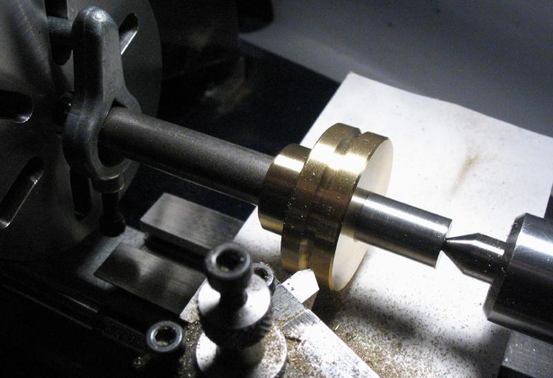
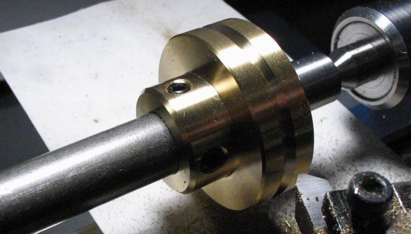
The pulley was then attached and the turning of the vee-groove completed using the compound slide set to 45 degree angles.
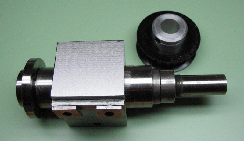
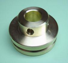
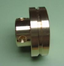
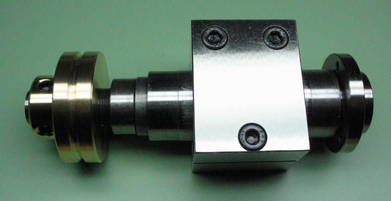
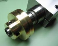
The completed pulley, along with photos of the spindle with standard Davall (P22XL037) pulley removed, the spindle with replacement pulley installed, and the final assembly.
