Tourbillon Carriage
The tourbillon mechanism is detailed and explained ad infinitum in numerous books, magazines articles and websites. Since I have nothing really novel to say about it, I will direct the reader to go elsewhere for a full explanation. I do not speak any French, and upon looking up the translations of the term, they include: vortex, whirlwind, swirl, and perhaps the most appropriate, 'merry-go-round.' The invention of this mechanism is attributed to Abraham Breguet. It was intended for use in pocket watches to average positional rate variation by continuously rotating the gravitationally sensitive components. For an entertaining and somewhat satirical perspective on watch complications, including the tourbillon, I refer the reader to an article which appeared in the NAWCC Bulletin (April 2007) written by Richard Watkins and can be found on his website.
While the tourbillon may or may not be a legitimate enhancement to the timekeeping ability of a watch, I think it is a rather clever idea and is entertaining to observe. Since my best chance of owning one is if I make it myself; I shall proceed with it ...
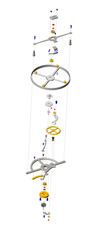
The 'tourbillon' is composed of a number of different parts, the balance and escapement are described on separate pages. This page will describe the construction of the carriage which carries the various components.
 |
|
Carriage Plates
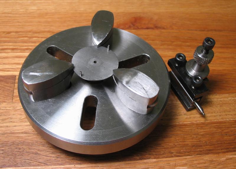
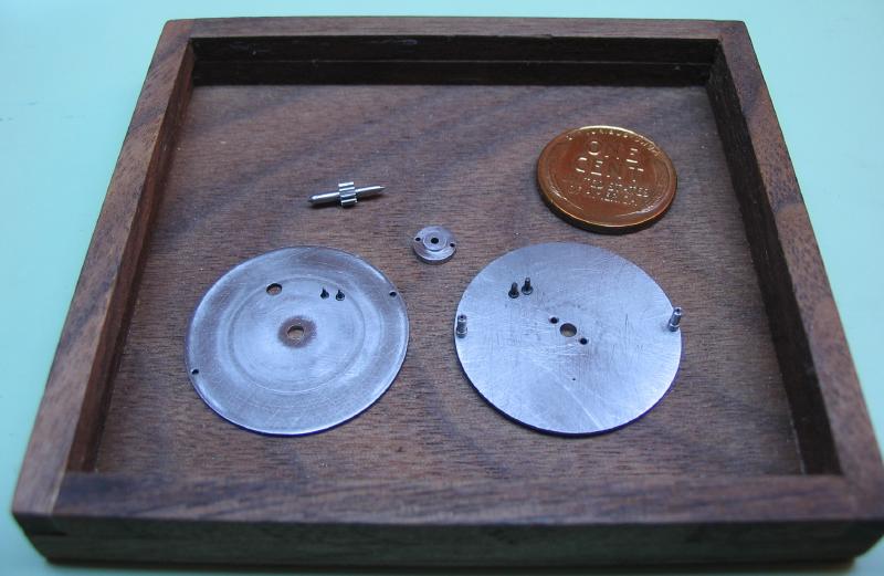
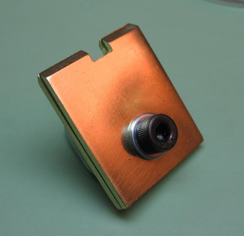
The carriage consists of an upper and lower bridge, made from steel plates and separated by two pillars. The balance and escapement are mounted within these plates.
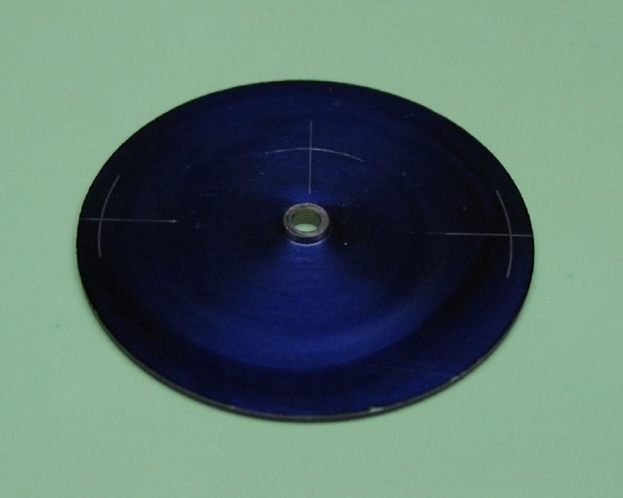
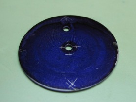
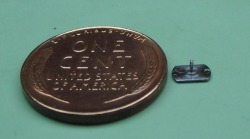
The plates are made from O-1 steel gauge plate. Since metric gauges were not readily available, the lower plate is made from 1/16" and the upper plate from 1/32" (the closest Imperial size). The outside diameter is 26.5mm, with the steel coated in layout fluid, this diameter is scribed onto the surface.
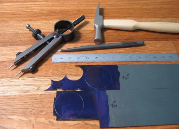
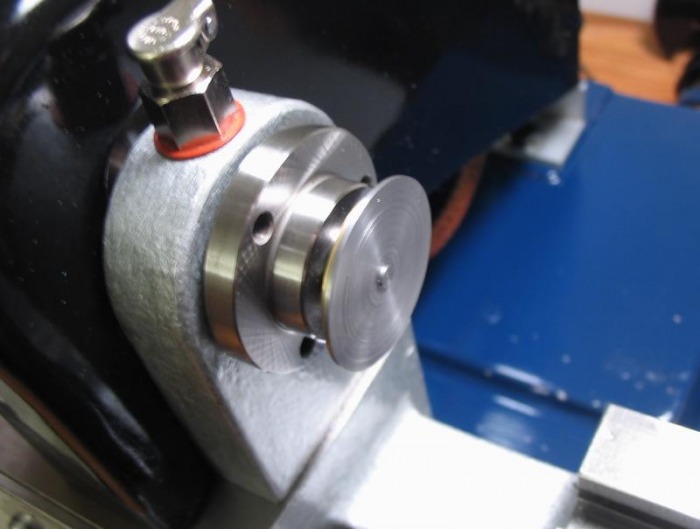
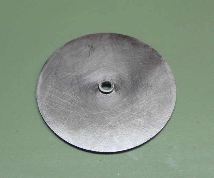
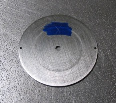
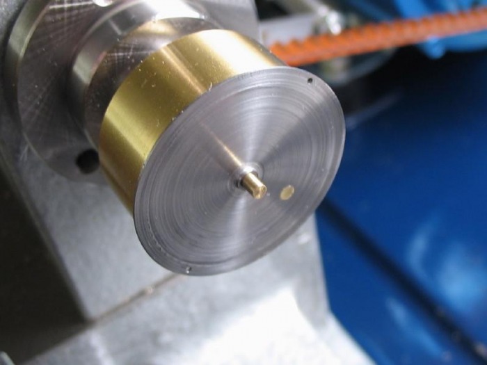
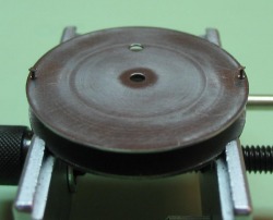
The discs are roughly sawed out with the piercing saw. Starting with the lower plate, it is lapped smooth on one side using 150 grit emery paper on glass. This side was then fixed onto a superglue arbor. It was turned to full diameter (26.5mm) and faced to a thickness of 1.3mm. It was then turned to a thickness of 0.8mm with a central boss of 3mm diameter and 0.5mm height.
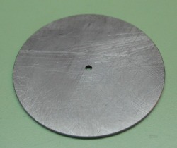
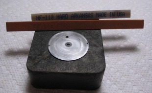
The disc is removed from the arbor and annealed to relieve any stresses induced from the machining. To do this I placed the disc onto a small brass block and heated both with a torch, once both were quite hot I picked the disc up with soldering tweezers and continued heating the disc to bring it up to a red heat. It was then placed back onto the hot brass block to allow to cool as slowly as possible. This process anneals the steel, thereby softening it.
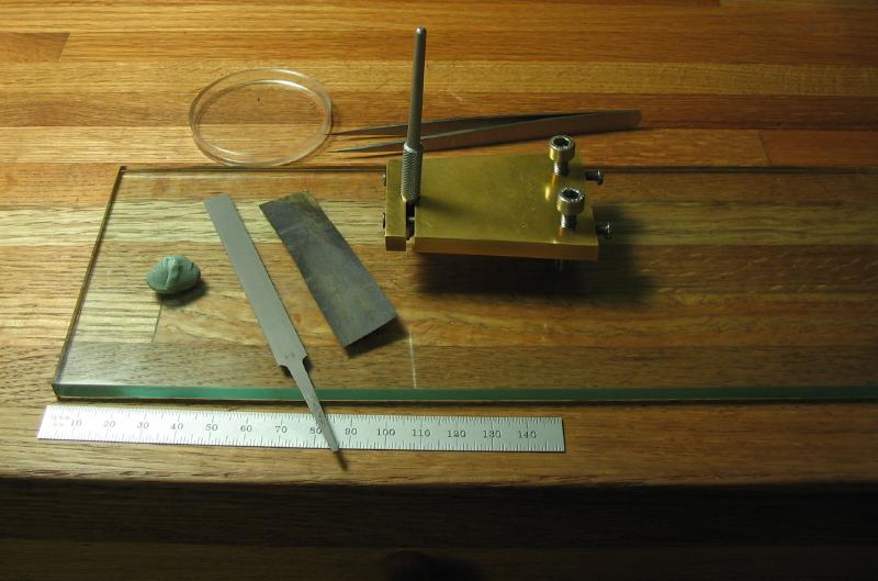
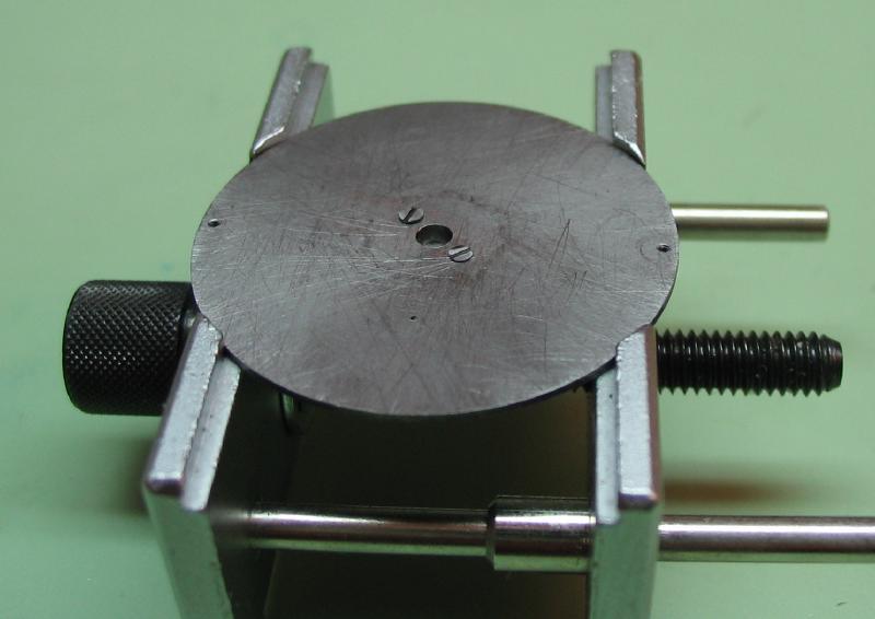
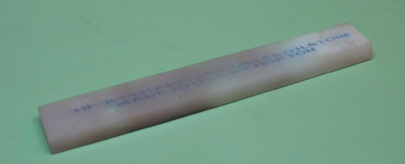
The disc is then checked for distortion in the flat. Daniels provides details for correcting the plate for any warping or bowing. My disc did not have any measurable variations. It is then placed onto a rubber block and filed flat initially with a Grobet No. 2 cut hand file with safety edge. It is then smoothed with a triangular fine India stone (Norton FF-114). The disc is brought down to a thickness of 0.6mm.
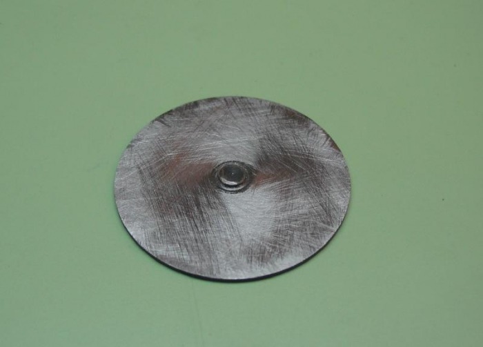
After some coarse filing.
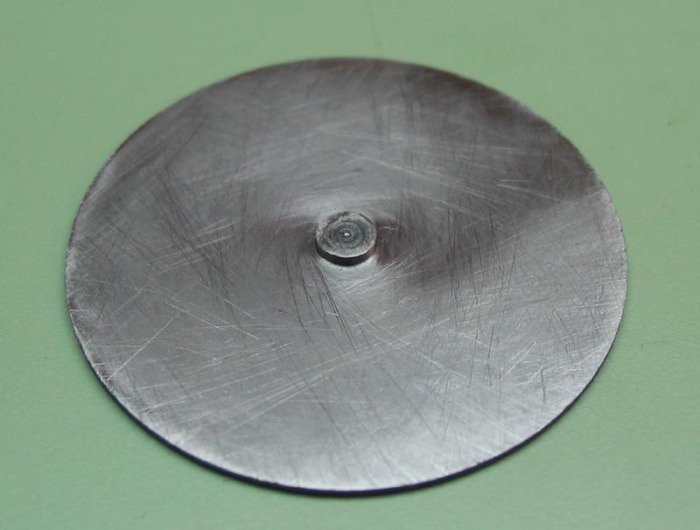
After stoning down to an even thickness (0.6mm), damage to the central boss will be corrected later when it is turned down to its final diameter.
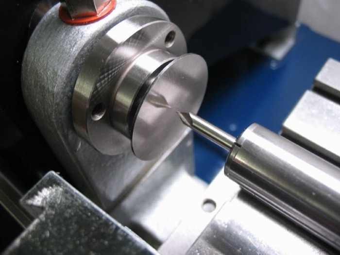
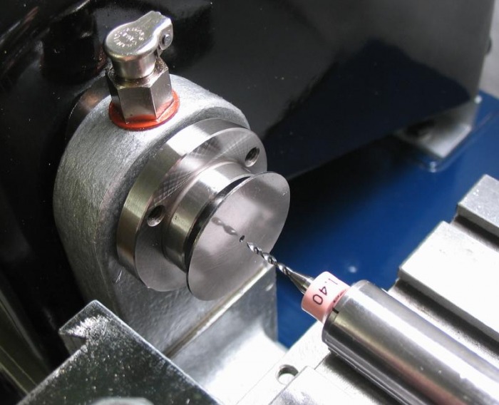
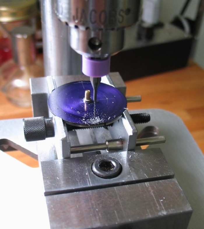
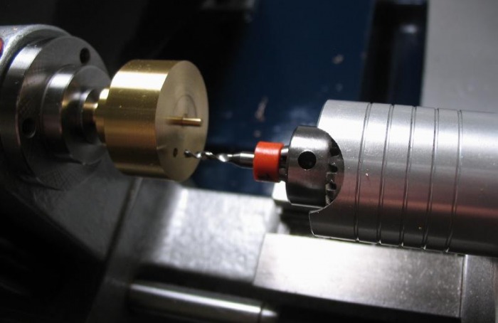
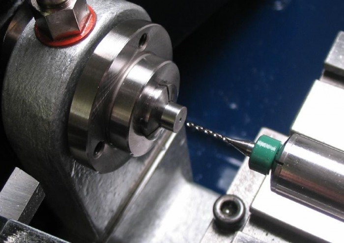
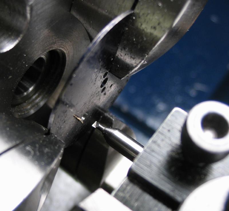
The plate is held by the boss in a collet and drilled 1.4mm. The hole is then bored open to the diameter of the jewel setting minus 0.2mm. I planned on a jewel setting of 2mm, hence the hole is opened to 1.80mm. A plug gauge was made to monitor the boring progress.
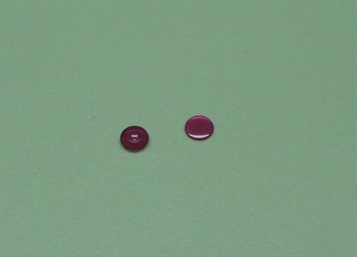
The choice of balance jewel was limited. I could not locate Incabloc style jewel parts of the dimensions suited for the carriage. I have decided on a much simpler system, although it is not a shock absorbing system. The setup was used in New York Standard watches are described by A. Perkins in his book "The Watchmakers Staking Tool."
"...The New York Standard Watch Company used friction style balance hole and cap jewel settings in most of their watches. Both of these settings were frictioned into a straight hole in the plate and balance cock. This style of arrangement allowed the endshake to be changed by staking the settings up or down in their hole. The same method is used to remove and replace these settings. One disadvantage to the New York Standard method
is that when the settings are removed a note must be made as to the location of the settings in their hole so that they can be replaced at the exact location from which they were removed..."
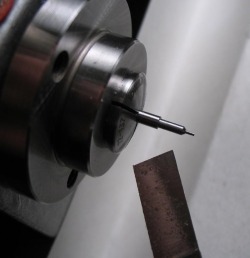
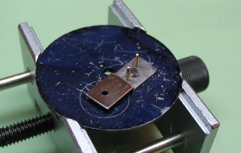
The plate is then mounted onto a brass pin turned in situ to friction fit the 1.8mm hole. The boss can then be turned down to 2.7mm.


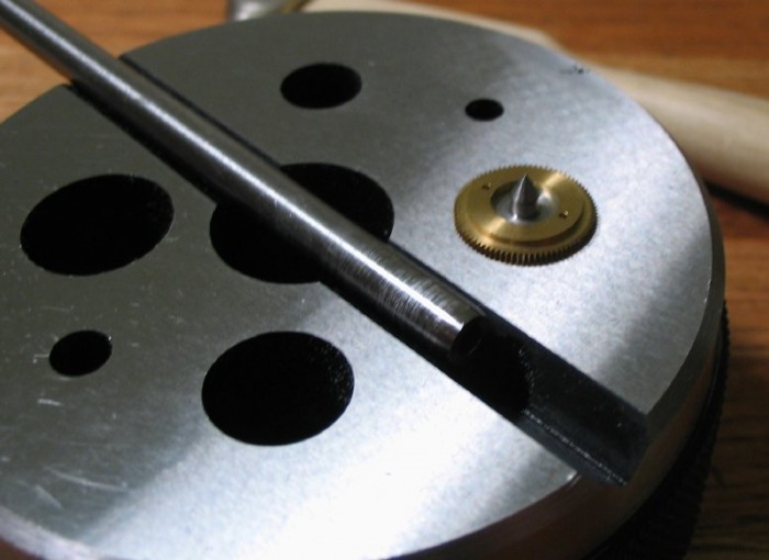
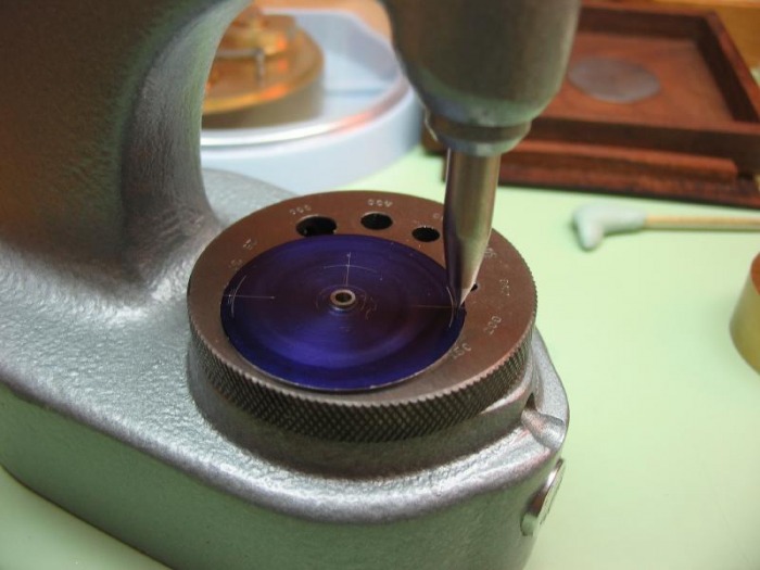
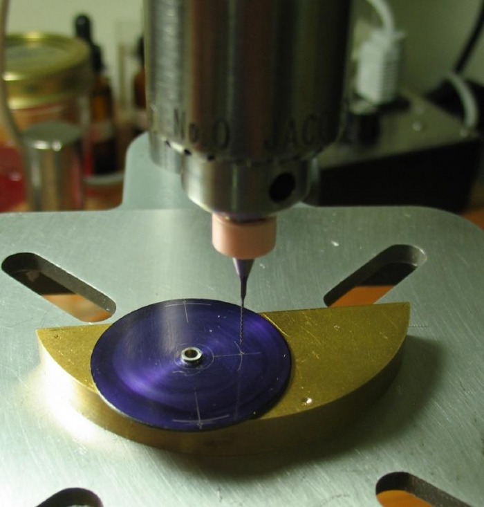
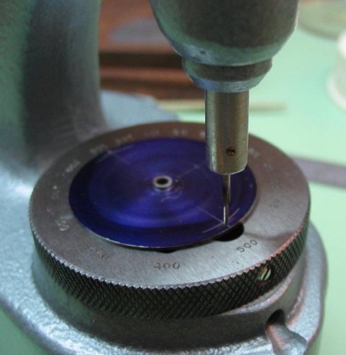
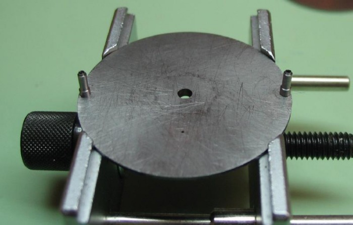
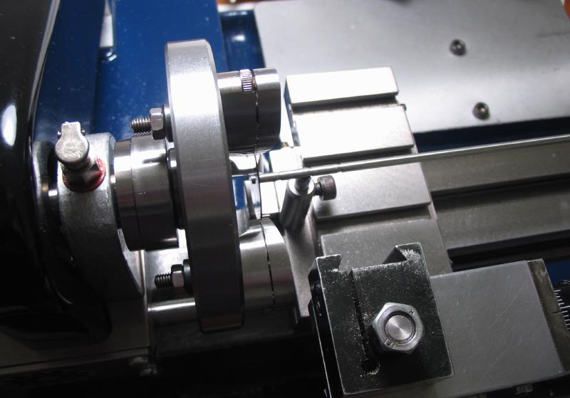
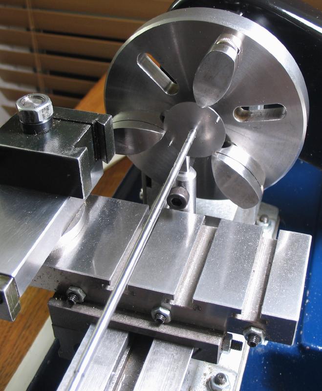
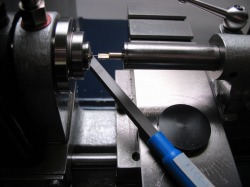
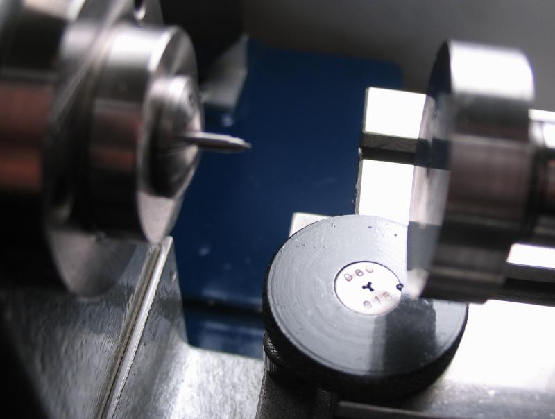
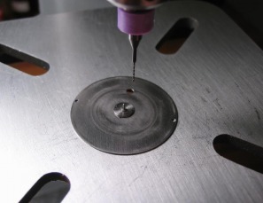
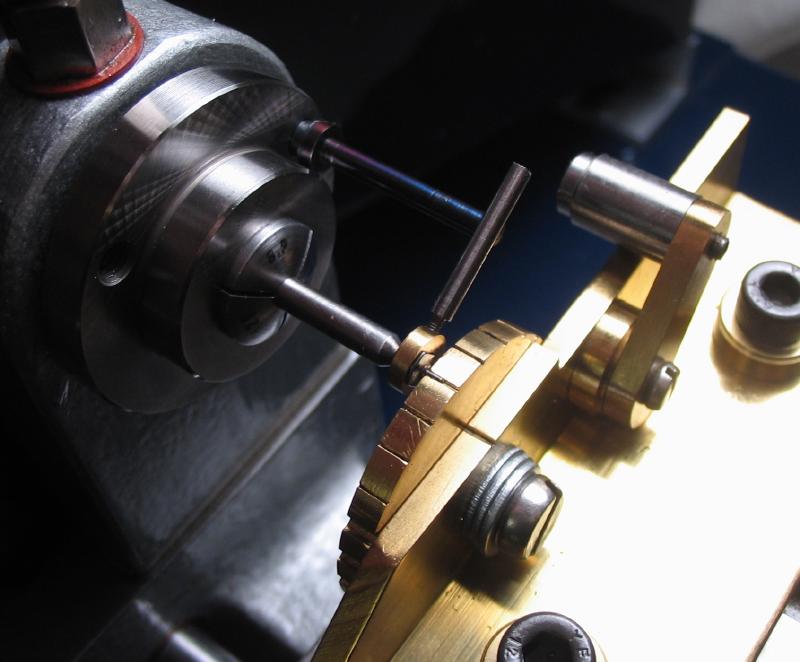
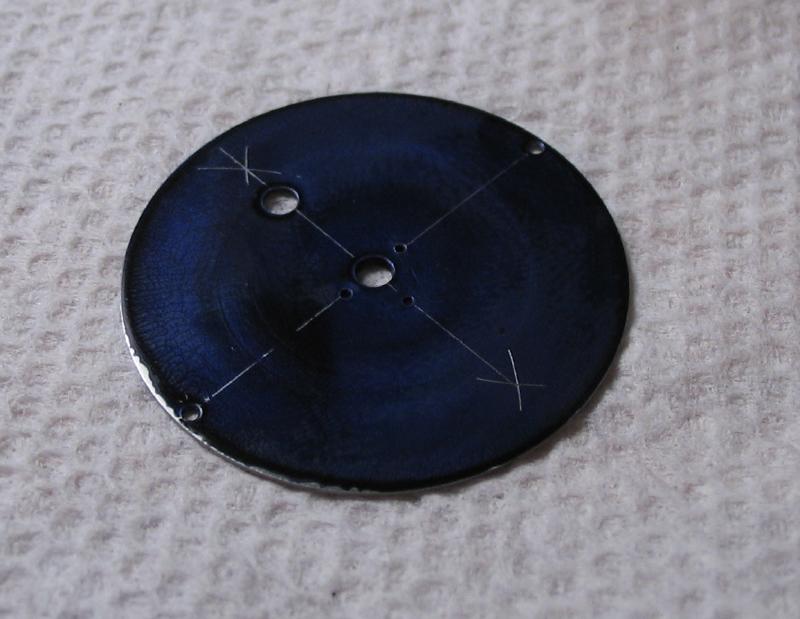
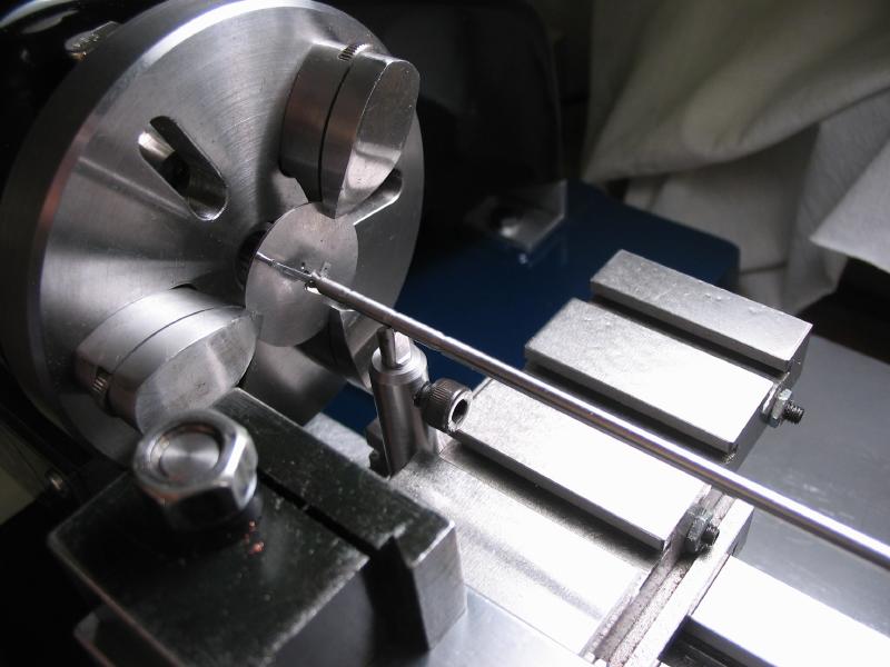
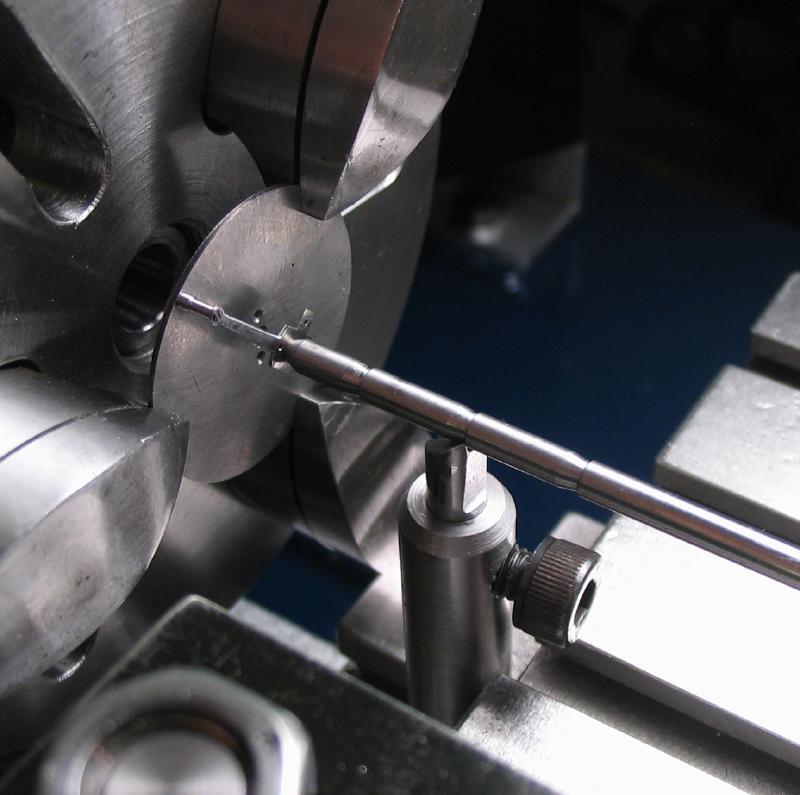
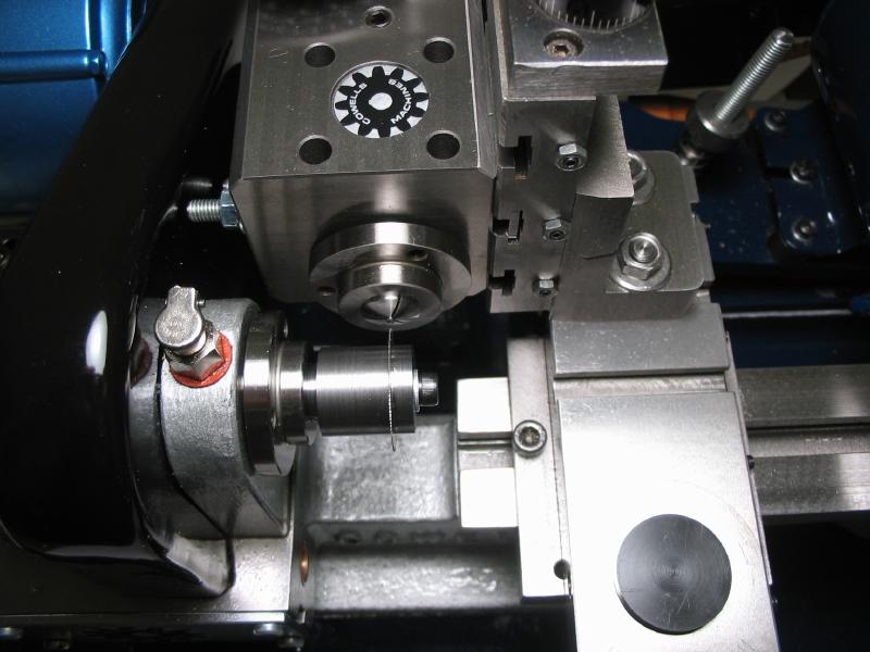
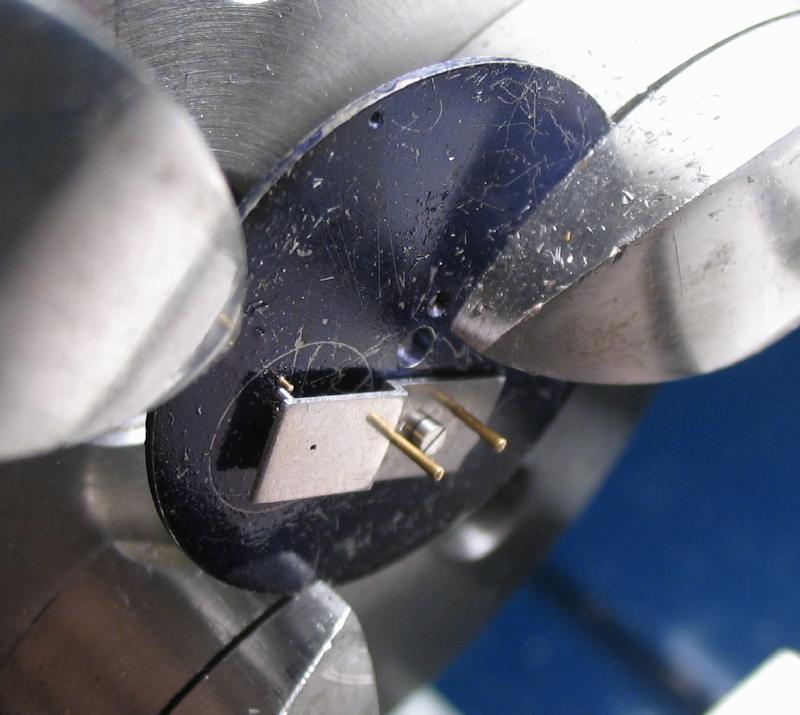
The radial positions for the pillars and escape wheel can be scribed onto the plate using the headstock to index and the cross slide to scribe. Daniels mentions using the cross slide tool to scribe and then use a compass to scribe the radial dimensions. I do not completely trust the cutting tool for scribing and measuring 11.95 mm with a compass is not easy. To scribe with the tool post, I made a center from 1/8" drill rod to fit a the small tool holder I made for 1/8" boring tools. The center is hardened and tempered to straw. After centering the tool post, the positions, including the 11.95mm radius for the pillars can be scribed using the headstock to index and the cross slide thimble to measure.
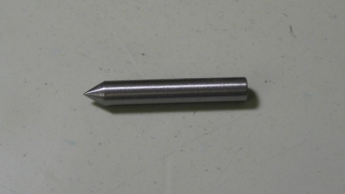 Turned |
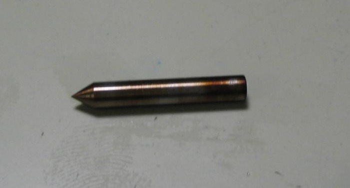 Hardened & Tempered |
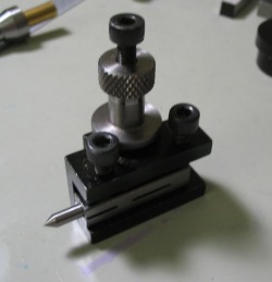
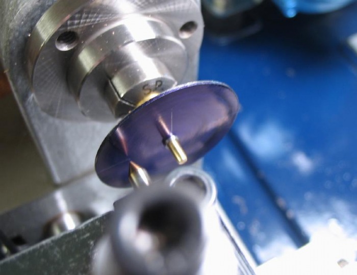 Scribing |
 Scribed |
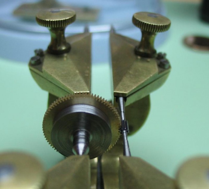
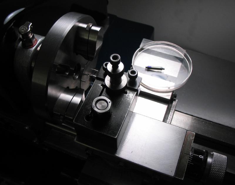
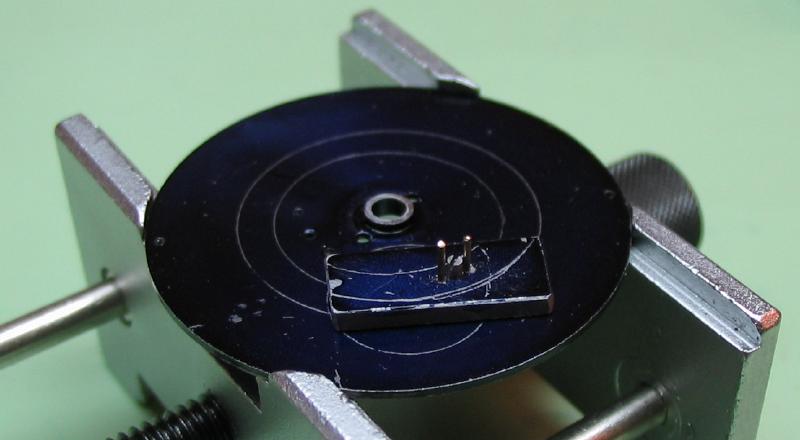
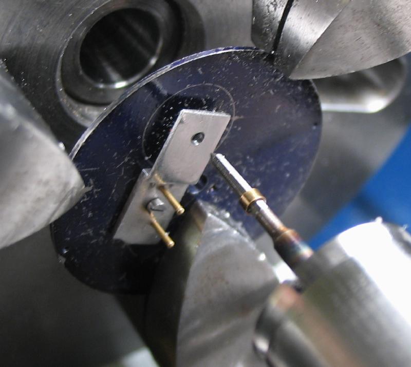
The depth between the fourth wheel and the escape pinion was determined and scribed onto the plate. Since the fixed fourth wheel is bored open, it was mounted in the depth tool using a special made arbor. I made a drawing and turned a simple arbor with male centers and a central hub. The hub can be turned to its final, friction fitting diameter (~9.2mm) by turning between centers, to ensure it is concentric with the centers.
The arbor was press fitted onto the fourth wheel using the staking tool.
The theoretical depth is 6.6mm based on the calculated pitch circles. Finding the 'sweet spot' by hand and eye can be tricky, and the theoretical depth is a good starting point (assuming the parts were made to specification). By measuring the diameter of the runners, you can use a micrometer to measure the depth.
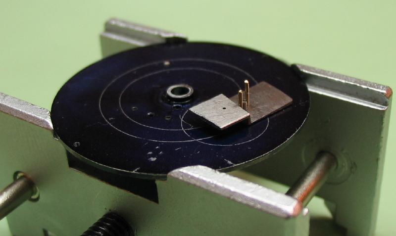
Once the depth is found, the trumpet runner can be swapped in and the depth scribed onto the plate.
| Fourth Wheel Depthing Arbor - hand drawing |
  |
  |
The depthing arbor is too large to be removed in the staking tool, and a toolmaker's bench block was used as a base and a flat punch was used to drive it out.
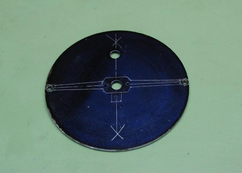
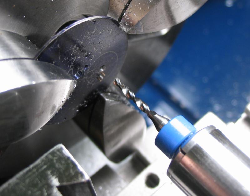
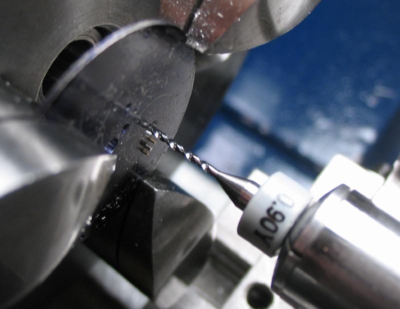
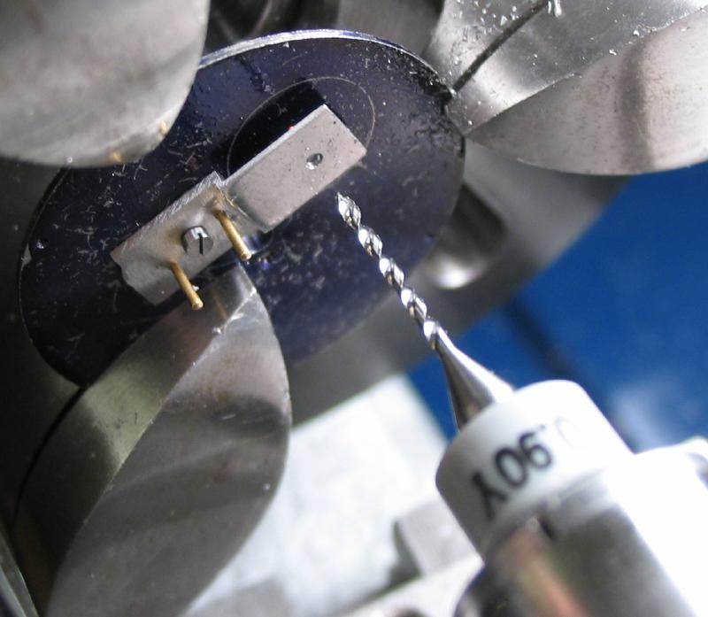
Although Daniels specified the pillar radius as 11.95mm, after pondering on it, I recalled that the balance wheel, made to Daniels specifications is 23.4mm in diameter. The pillars need to be moved out to at least 12.2mm to have running clearance. I re-scribed the pillar radii on the lower plate. The scribed intersections can now be drilled undersize (0.35mm).
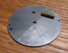
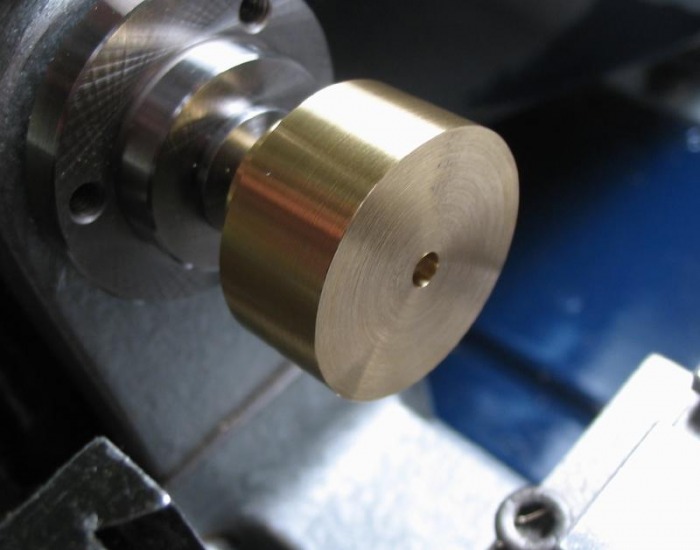
The top plate to the carriage is made from 1/32nd inch gauge plate. It was lapped smooth on one side and affixed to a arbor and turned down to 0.7mm in thickness and to 26.5mm in diameter. A pilot hole was drilled, this gets opened to the same diameter of the lower plate so that the two plates can be mated onto the brass pin.
Note that the lower plate is inverted on top of the upper plate, this relative position will now be permanent. The two plates are marked for position, and can then be drilled for the pillar locations with a 0.48mm drill (for 0.6mm threads). Daniels specifies a #12 Martin thread for this, but taps and dies are no longer made, as far as I can tell, in this system. I believe this is the system used in the old die plates which show up on Ebay. I would prefer to use modern taps/dies and not fuss with one of these plates, since they are not easily found in good condition (taps would then have to be made from the plate, and so on). Bergeon (NIHS) taps of 0.6mm have a 0.15mm pitch, so there will be 4 thread turns available to secure the posts to the plate.
The lower plate was tapped.
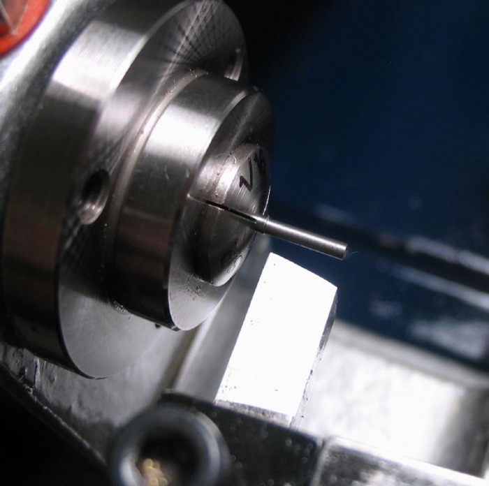
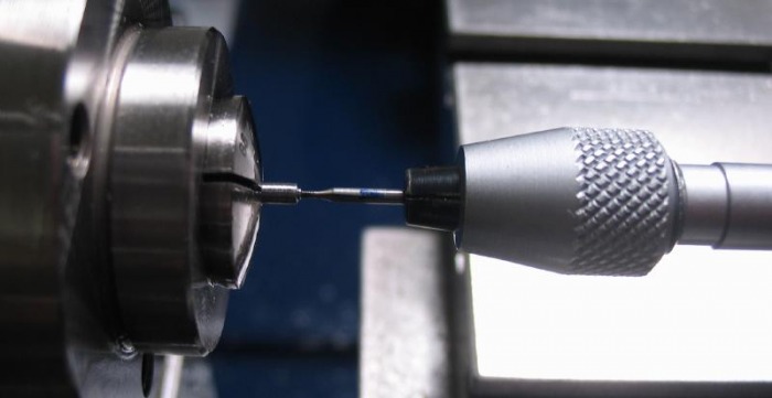
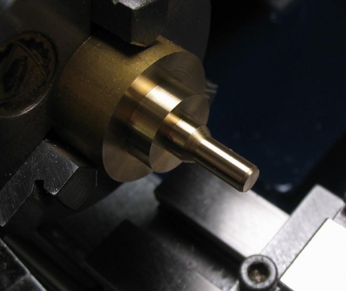
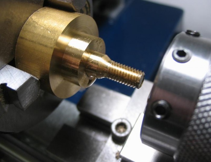
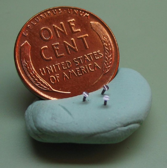
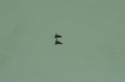
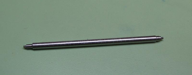
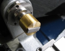
The posts are made from 1/16" O-1 drill rod. Turned down to 1.4mm and a locating boss turned slightly over-sized (~0.75mm x 0.25mm). The end is center drilled (The tip of the hole is coned to the edge so that a center can be used later during finishing) and drilled and tapped 0.5mm. Daniels warns the reader early in his book that tapping parts like this where tapping a small diameter in steel for a long length as one of the more difficult tapping operations the watchmaker will need to undertake. The post is drilled (0.4mm) for a length of 2mm and is tapped for 1.5mm of that. This must be done slowly and the tap frequently cleared to remove chips, the tap is liberally oiled. A cutting or tapping fluid can help. These small taps are delicate, relatively expensive, and will not tolerate misuse. But with care they work well.
| Carriage Pillars |
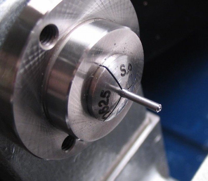
The length is established with the parting tool and then the post is parted off with a sharp, pointed tool (actually a threading tool) to produced a center on the parted end. The post can be held in a 1.4mm collet and the threaded portion turned to size (0.58mm), followed by threading with a 0.6mm die. A slight undercut is given the flange so that the posts can be threaded all the way up.
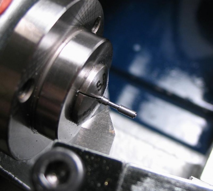
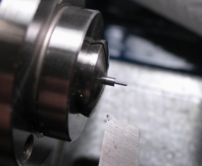
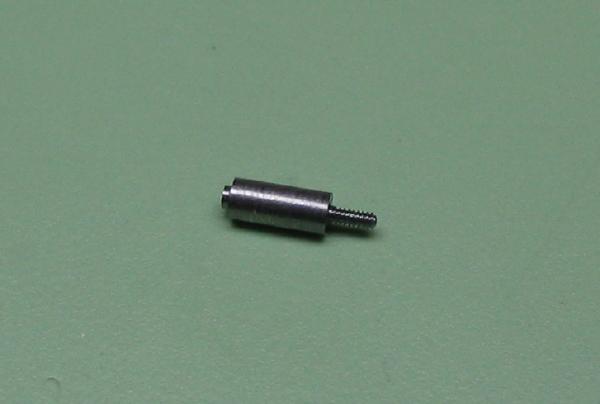
The posts are then hardened and tempered blue. They are cleaned up with chromium oxide (green paste) with oil on wood. The threads cleaned out with an oily tap and then rinsed in benzine. The post can be fit to the bottom plate and the threaded post shortened to fit. One is marked for location. They are then put back into a 1.4mm collet and centered with the tailstock. The locating boss and shaft turned to final dimensions.
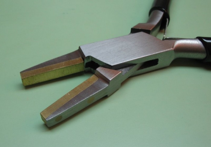
Daniels recommends using brass lined pliers to tighten the posts to the plate. These can usually be purchased from jewelers' supply houses.
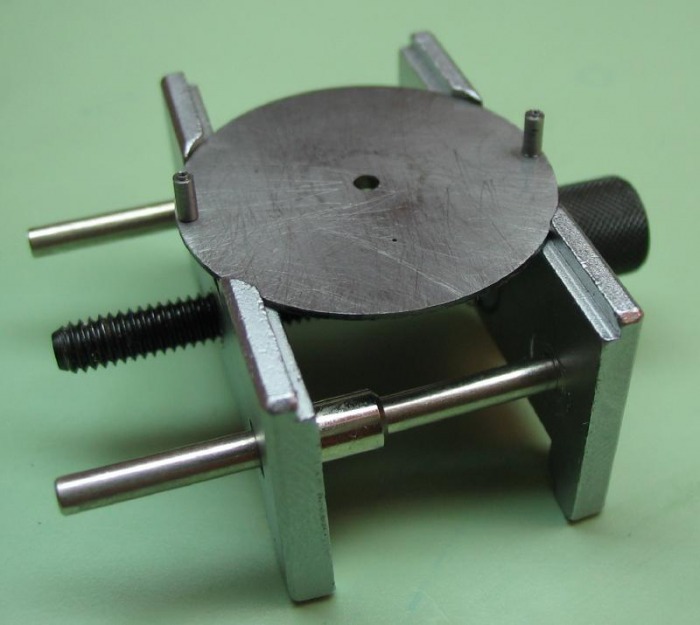
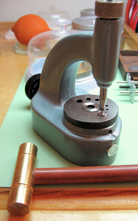
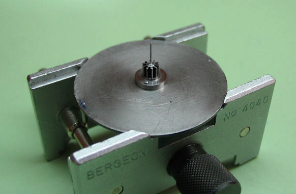
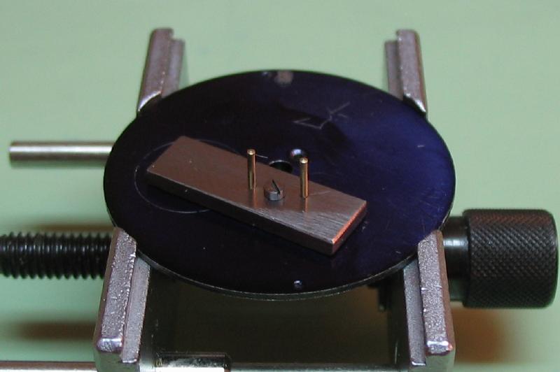
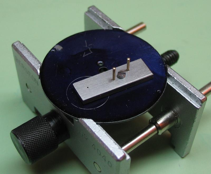
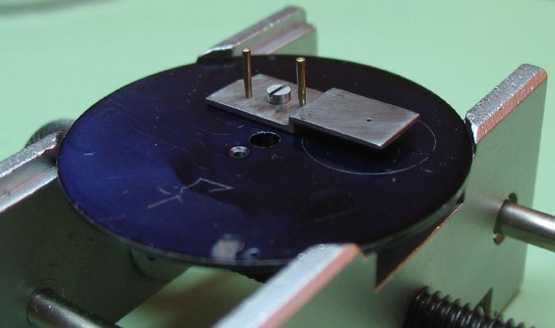
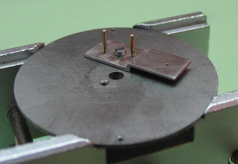
Just as a note, the carriage fits nicely in a Bergeon No. 4040 movement holder.
| bergeon_4040.pdf |

The posts were gripped in a 1.4mm collet turned using a hand graver.
The top plate can then be opened to fit the posts. One hole is broached to fit, and the second hole is then broached. Daniels states that if the alignment is not correct, then the work is ruined and should be restarted. Fortunately, the fit was quite good, and the broached holes were left fairly tight. The holes are chamfered to fit angle head screws. Once again a pair of screws need to be made, having the angled heads and also a plain diameter tip which assists during the assembly process. This is described in 'Watchmaking.'

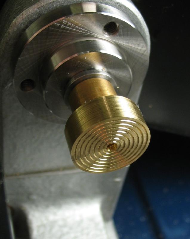
The top plate, which is to become a bridge, needs to be faced down to a thickness of 0.35mm, with a central boss 2.6mm in diameter. This boss will contain the top jewel settings. To perform this facing operation, a driving arbor needed to be be made. The plate is pre-drilled for the brass driving pin.
 |
 |
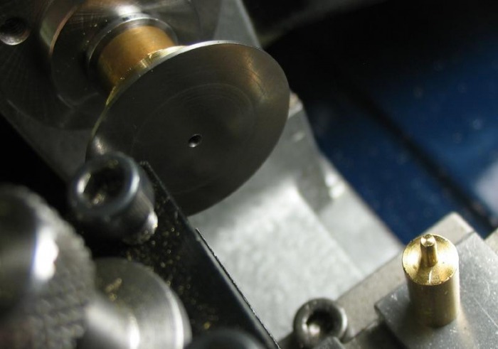
The top plate is mounted on the drive arbor and was faced down. This didn't go as well as I had hoped. I think the setup is simply not secure enough. I think this would have gone better if it was simply super glued into place on the arbor. The risk with that method is that the thin film of glue on the face of the arbor can affect the truth in the flat. For something so thin and dimension critical, the plate could have an uneven thickness.
The result was some coarse facing. The lathe tool tended to grab the work.
 One inch brass rod turned to basic cement chuck dimensions. |
 Threaded M5x0.8 to fit collet. |
 Fit to collet and drilled to friction fit 1/8" brass rod. The rod is turned to fit the center hole of the carriage plate. |
 The hole for the driving pin was drilled using the Foredom mounted on the top slide. |

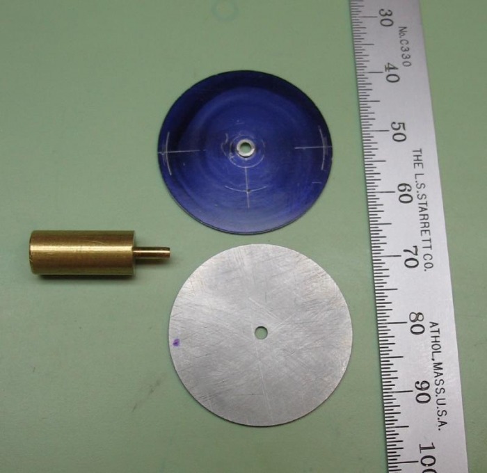
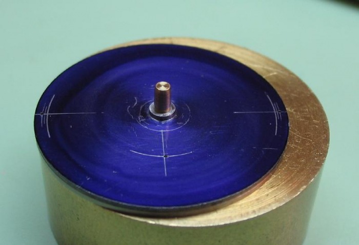
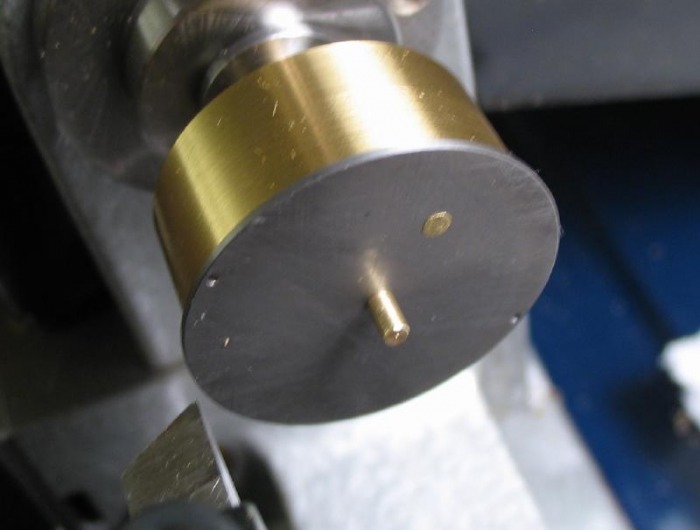 Plate |
 Faced to 0.35mm |
The plate was then stoned on both sides to remove tool marks. A fine, triangular India stone slip followed by a triangular hard Arkansas slip was used.
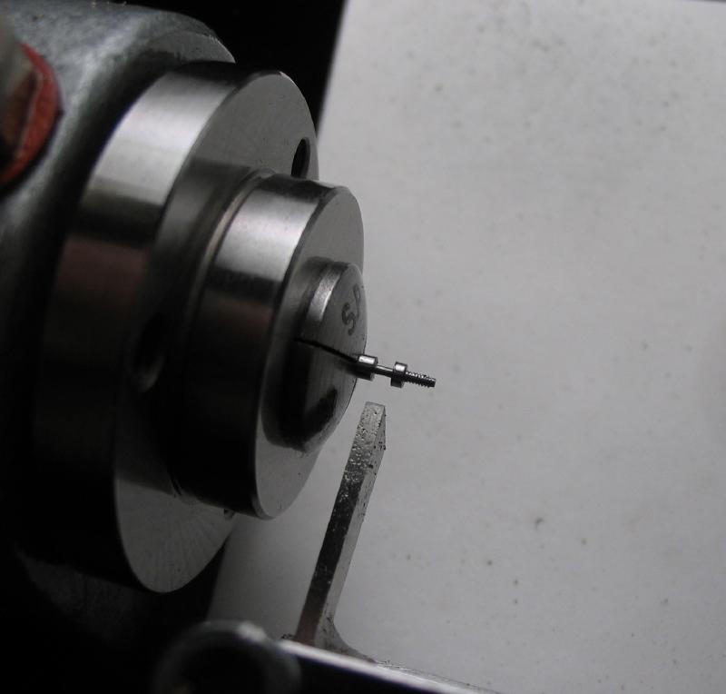
The screws were some of the more difficult that I have made so far. They are quite small, with 0.5mm threads and a small countersunk head. Daniels recommends a short, unthreaded tip to assist in assembly. Upon finding the first batch unacceptable, for being too long in the threads, more screws were made until a pair were found suitable.
Aligning the plates
 |
 |
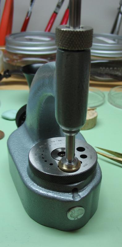
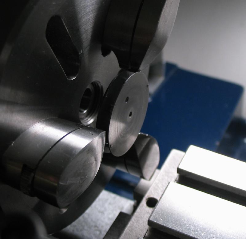
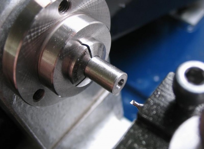
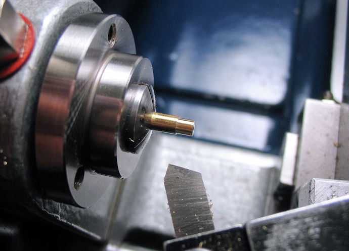
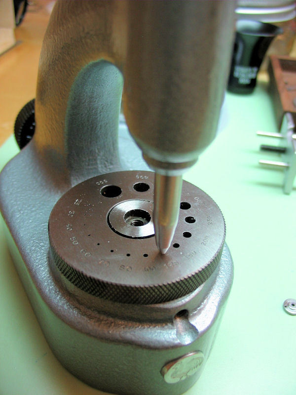
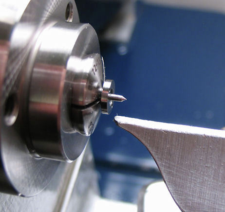
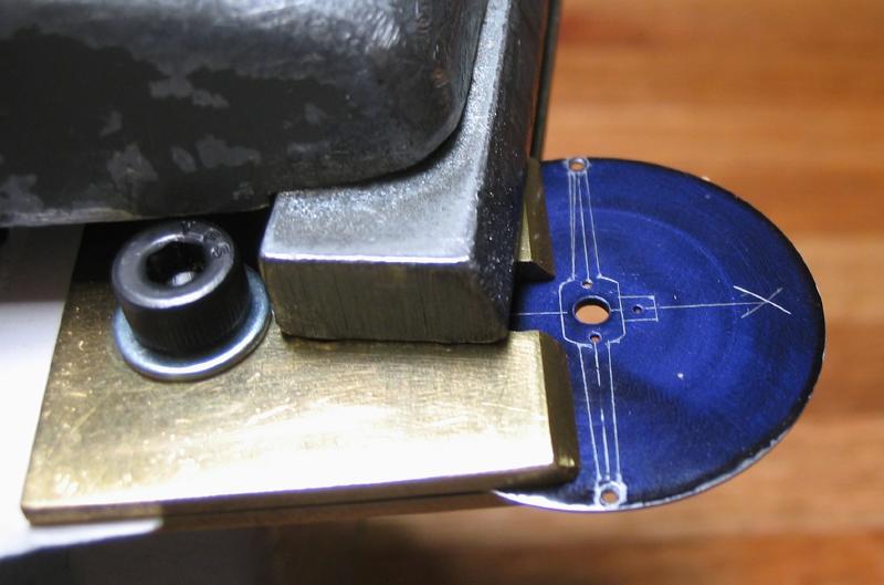
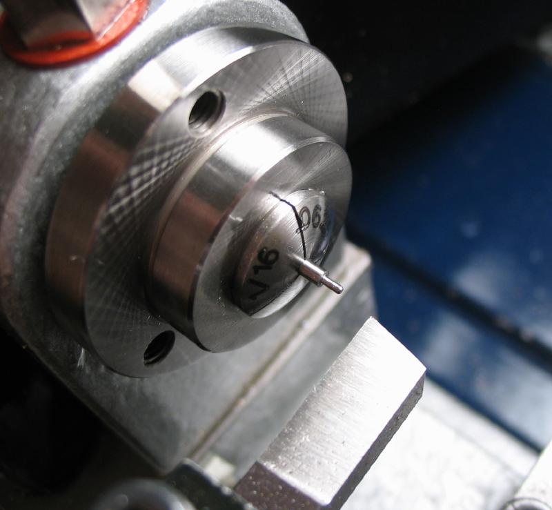
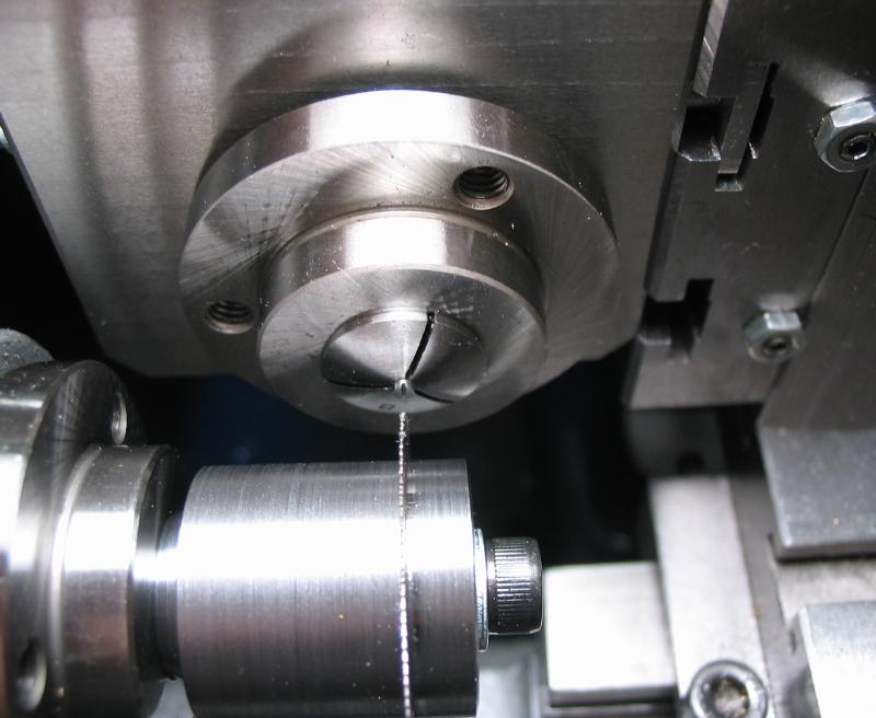
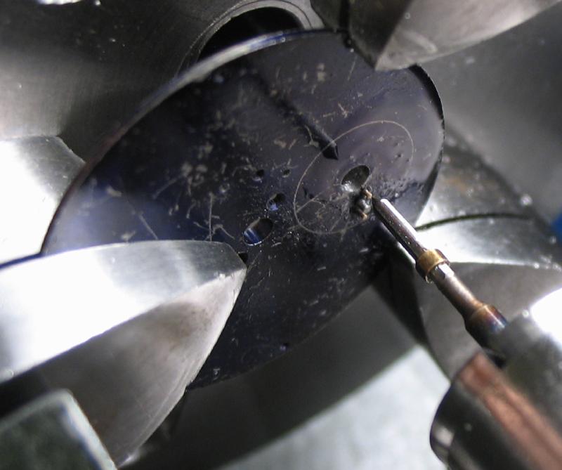
The hole is bored open to the final diameter minus 0.05mm (1.95mm). A plug gauge is used to monitor the progress (seen in the photo).
The hole is then finished with the jewelling broach (1.98mm) held in the tailstock and with plenty of oil to prevent the broach tearing the surface.

The top plate is then screwed on, and the process repeated for the top plate hole.
 |
 |
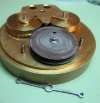
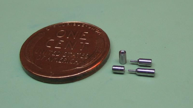
Carriage Pinion Collar
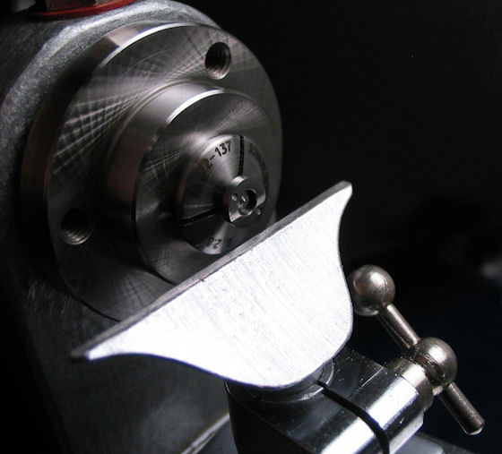
After drilling, the boring is made to fit the boss on the lower plate of the carriage (2.7mm x 0.6mm deep). A Micro100 (MBB-045100) carbide boring tool was used.
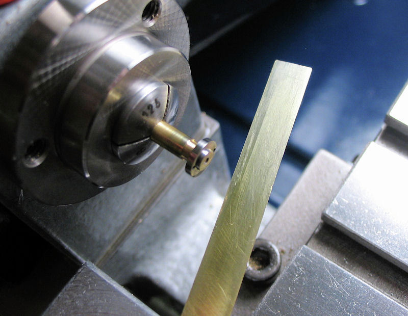
After boring, the final outside diameter can be turned (5.5mm).

The collar is then parted off to finish the other side. I used a left hand cutting parting tool to get a good finish on the bottom side of the collar and to cut the collar to the finished length (1.35 mm). Daniels recommends parting with a graver, which sounded more difficult to me.
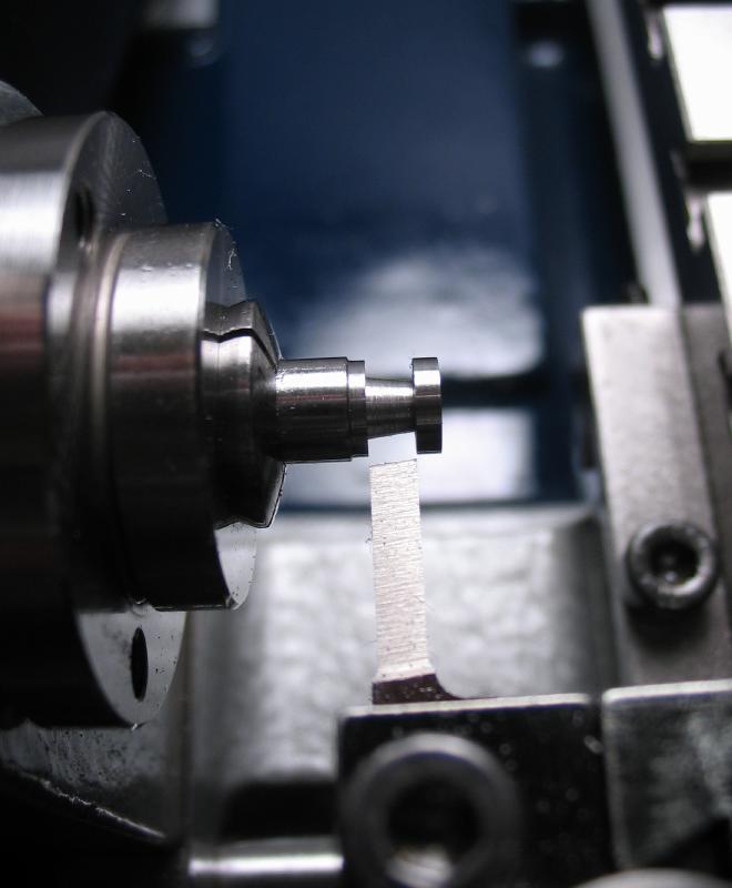
After parting, an arbor needs to be made for mounting the collar. A piece of brass rod was turned to just under 2.7mm and a further portion turned down to 1.0mm. The collar was then tapped on using the tailstock to ensure an evenly distributed force. A smear of super glue was put on the arbor prior to seating the collar, to keep things together.
 |
 |
The underside could now be turned to its final dimensions.
Fitting the collar
A pair of 0.8mm countersunk screws are made to suit.

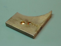
A simple jig was made from a piece of scrap brass plate to help hold the collar and plate steady while drilling. In retrospect, a better designed jig could be made, but this one got the job done.
 One screw fit |
 |
Then the other hole is drilled and tapped.

 |
 |
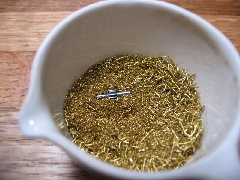
The collar is then hardened and tempered blue. Following that the collar can be polished to its finished condition. Once the pinion is attached it will not be easy to polish. To polish, it was again mounted on a brass arbor.

The brass rod is turned to fit the recess in the collar, and then to fit the center hole. These are left about 0.05mm oversize to give a tight fit.
 |
 |
The collar is polished with a mild steel polisher with green paste mixed with oil, followed by Simichrome on brass.
 |
 |
Carriage Pinion
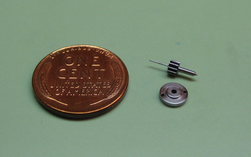
The carriage pinion, which would otherwise be the fourth pinion in a conventional gear train, can now be made. The carriage pinion is the fixture point for the seconds hand and is driven by the third wheel. It is friction fit to the collar which is screwed to the bottom plate of the carriage.
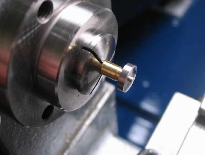
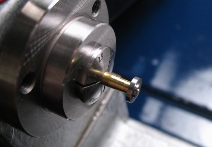
I started with 6mm O-1 drill rod (roughly twice the diameter of the pinion), and began turning the required dimensions.
Reduced to the calculated full pinion diameter (2.9025mm)

Turned the basic axial dimensions, which were deduced from a cross-sectional layout drawing. It was a back-of-an-envelope type drawing and things get fairly confusing at this point due the various bridge recesses, cocks and wheel engagements, etc. However the length of the pinion leaves was determined to be 1.8mm.
Click link for PDF of complete dimensions (pinion and collar)
| Carriage Pinion and Collar |
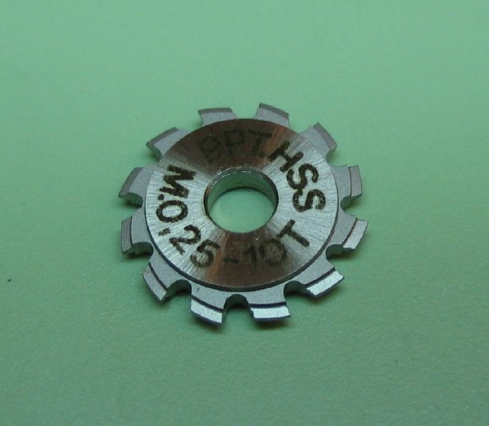
The carriage pinion is 0.25 module to match the third wheel and has 10 leaves to provide the 7.5:1 ratio. Incidentally this is the same module and leave count as the third pinion, so the same cutter can be used, which is financially advantageous for a change!
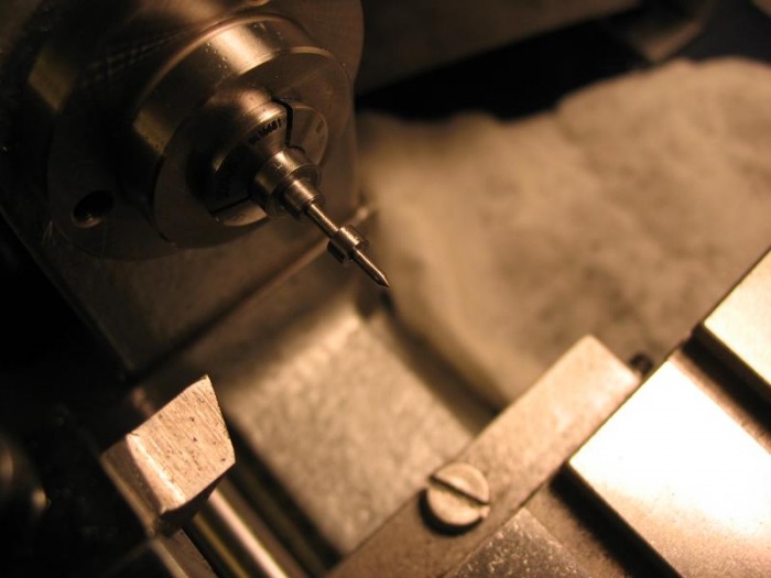
The milling cutter is setup and the speed reduction pulley is exchanged for the standard pulley to provide the slowest cutting speed available

Pinion Specifications
No. of leaves: 10
Pitch circle: 2.5mm
Full diameter: 2.9025mm
Root diameter: 1.475mm
Leaf thickness: 0.3125mm
Addendum radius: 0.205mm
Addendum form: 1/3 ogive
Tooth/pitch ratio: 2/5
Addendum: 0.20125mm
Dedendum: 0.5125mm
Full Tooth depth: 0.68875mm
Milling in progress, indexing is provided by the headstock pulley divisions (60 / 10 = 6).

Milling complete
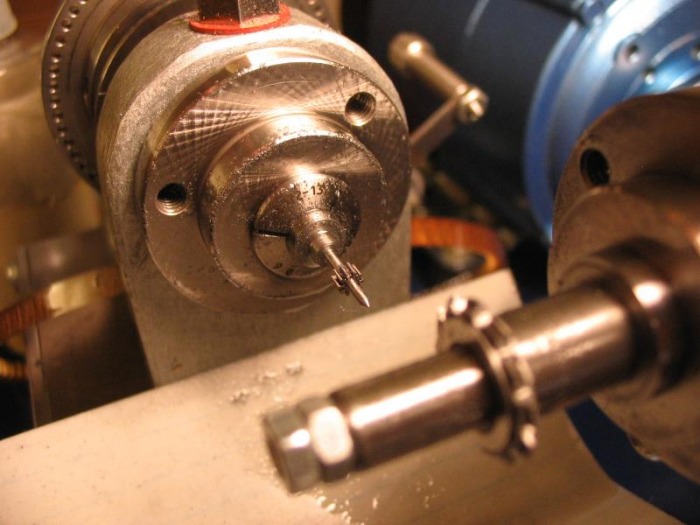
Pinion parted off with male centers turned on ends. These are re-trued after hardening and tempering.
Finishing and fitting the pinion
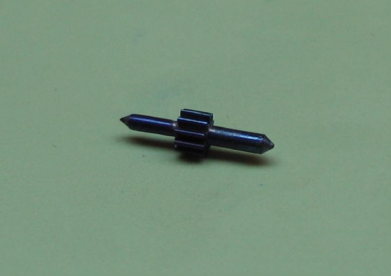
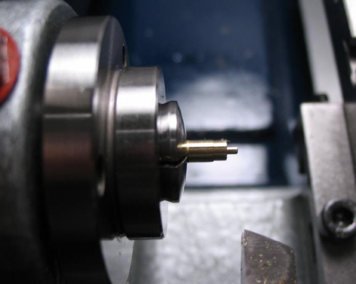
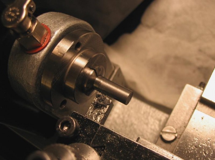
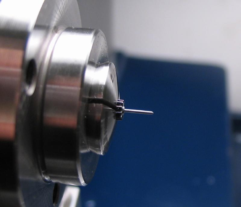
The pinion is held in a collet by its leaves and trued using the face of the graver against the edge of the leaves. Once trued the collet is tightened. The pinion is to be friction fit to the collar, the arbor on one side of the pinion is turned with a slight taper to give a tight fit to the collar bore.
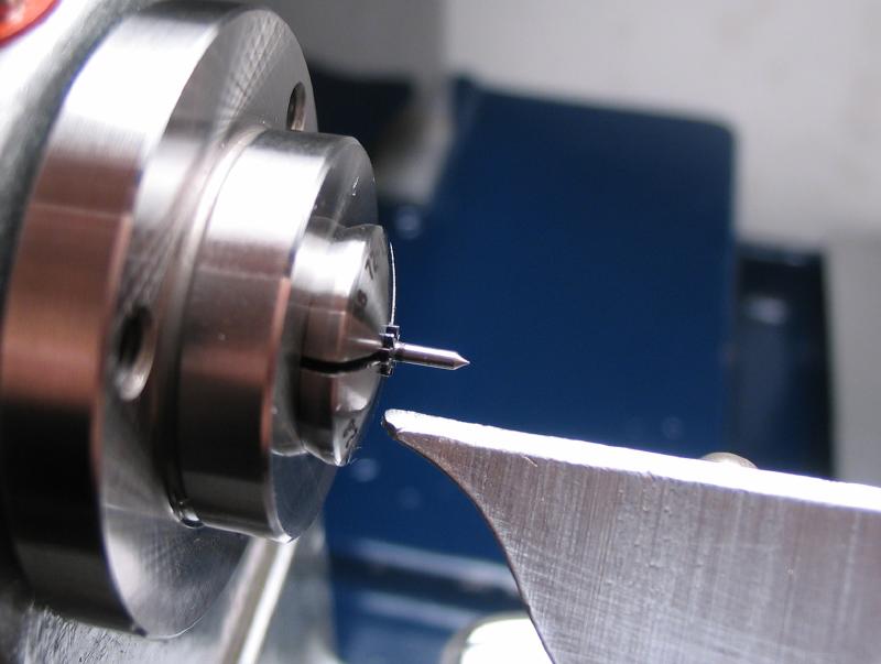
The other end is turned down to form the lower pivot and will also be the seconds hand post. Measurements are taken to ensure the pinion will ultimately provide 0.2mm of clearance between the carriage plate and the fixed fourth wheel.
The pivot was reduced to its final diameter using the support made while finishing the third pinion. The pivot file was used, however, I have found that I prefer to touch up with a HF-13 Norton hard Arkansas slip stone before burnishing. The Vallorbe, left-hand pivot burnisher was then applied.
 |
 |

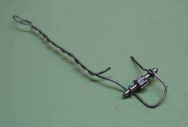
Staking pinion to collar
 |
 |
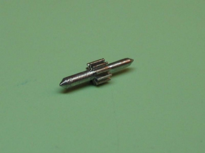
The pinion is then driven into the collar using a flat hole punch which clears the pivot shoulder (1.25mm punch). A brass hammer was used, the fit must be quite tight, as the pinion will drive the tourbillon and therefore the fit must be able to withstand the torque.
 |
 |
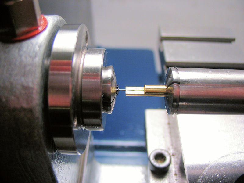
The surplus length of arbor can now be turned away.
 |
 |
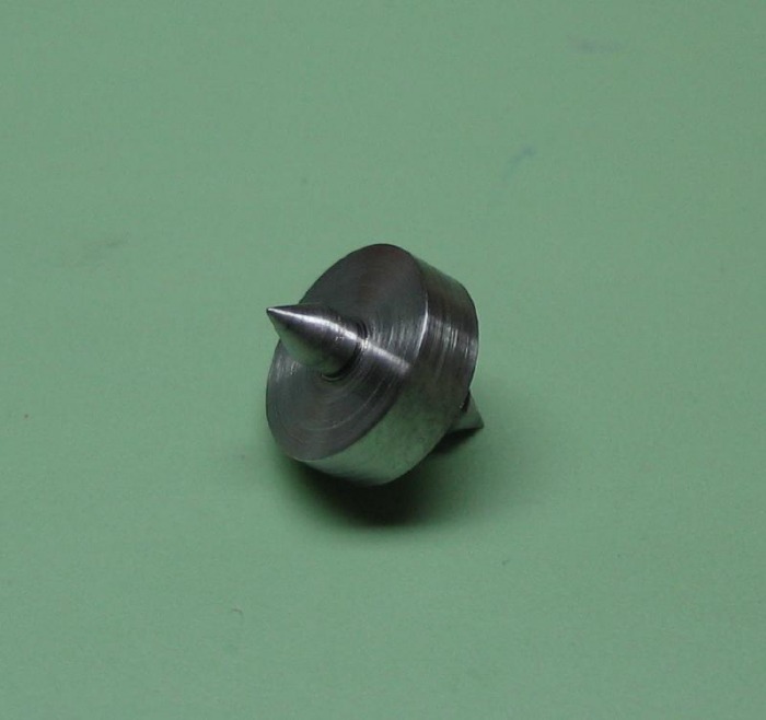
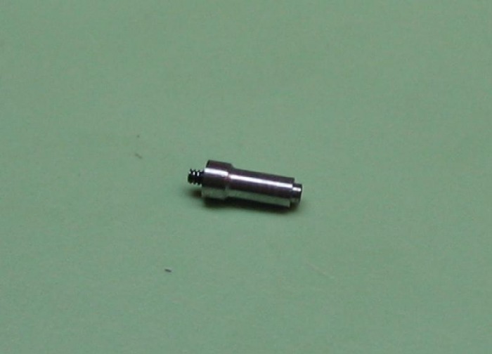
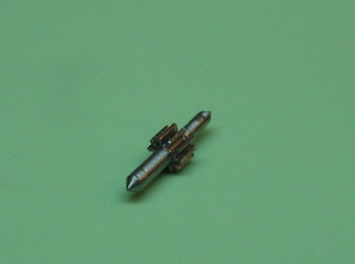
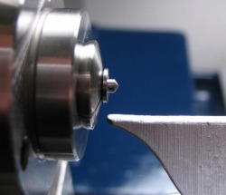
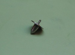
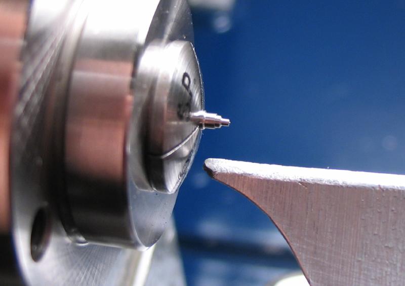
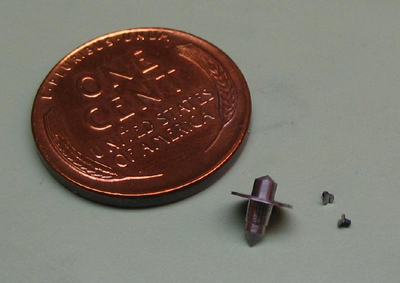
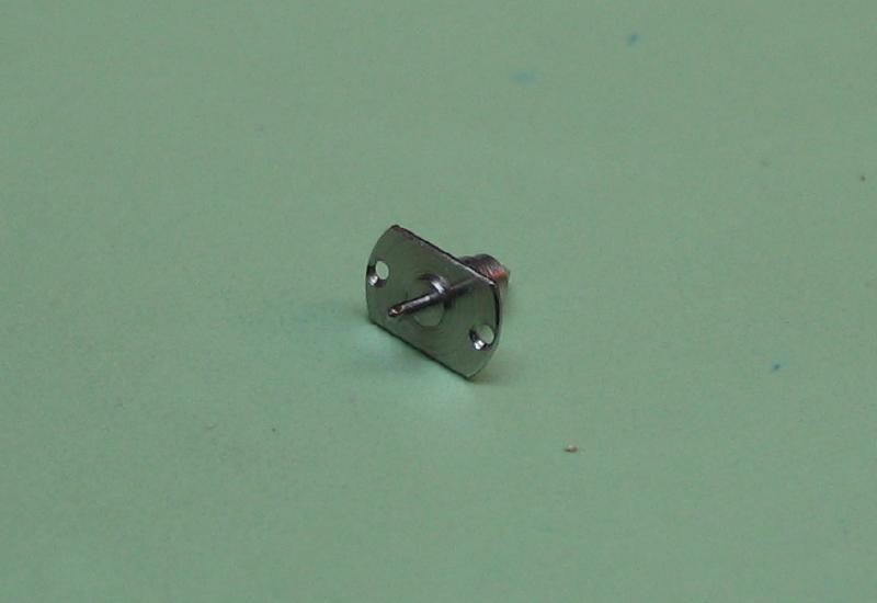
Top Pivot
It is made from 5mm O-1 drill rod. First it was turned to have a snug fit to the jewel hole, a surplus of arbor and a center is provided in the early stages.
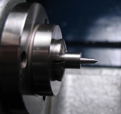
The flange is determined and the part can be parted off, forming a center at the same time. I used a threading tool in the tool post, but this could be done with a graver as well.
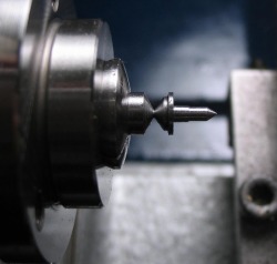
The parted off piece is reversed into a collet, and the top pivot shoulder is turned down and the flange dimensions can be finished.
The top pivot must be finished by hand turning between centers. This required some preparation, and I wrote up some details of this on a separate page. The top shoulder and pivot is turned down to size and to fit the main bridge jewel (0.50mm).

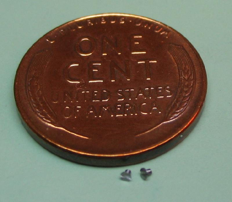
A pair of screws needed to be made to attach the top pivot to the top plate of the carriage. They have 1.0mm countersunk heads, and 0.6mm threads of only 0.35mm in length. They were hand turned from O-1 drill rod, both ends of the rod finished before parting off (no particular reason). Then finished as usual, hardened and tempered blue.
The layout for the top pivot screws are scribed on the carriage top plate. With the pivot in place, the holes were drilled for tapping to 0.6mm. The holes in the pivot flange are broached and countersunk to pass and fit the screws.
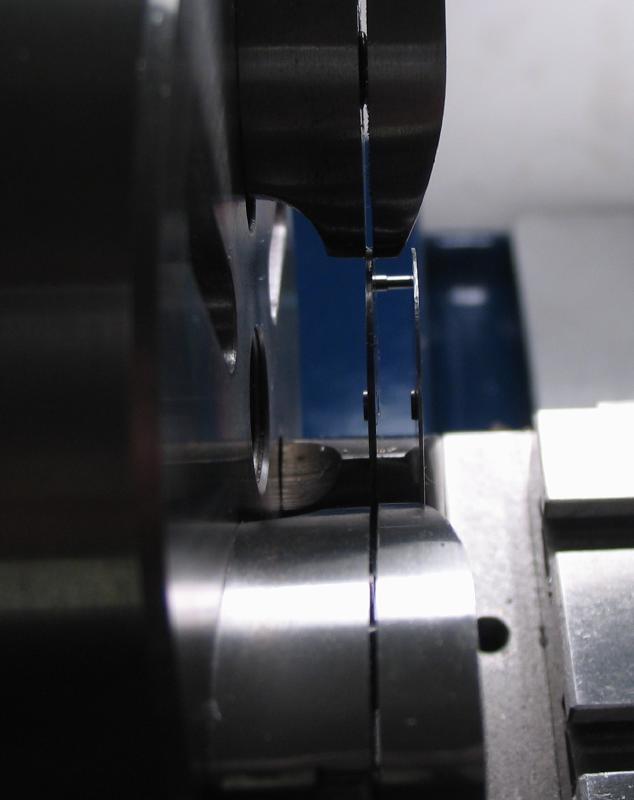
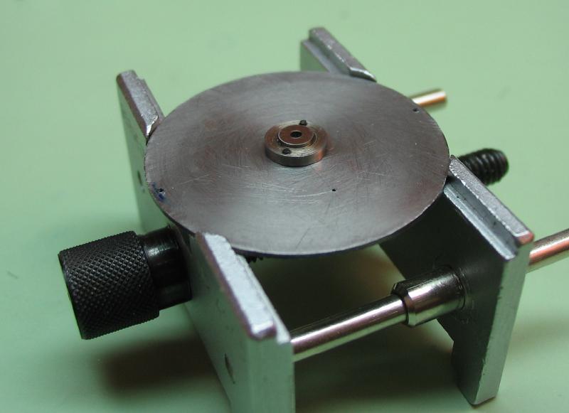
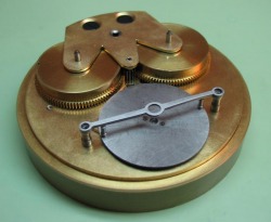
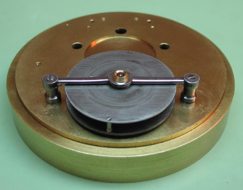
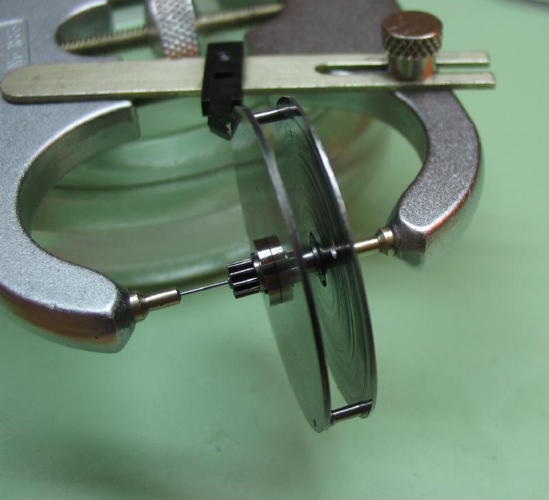
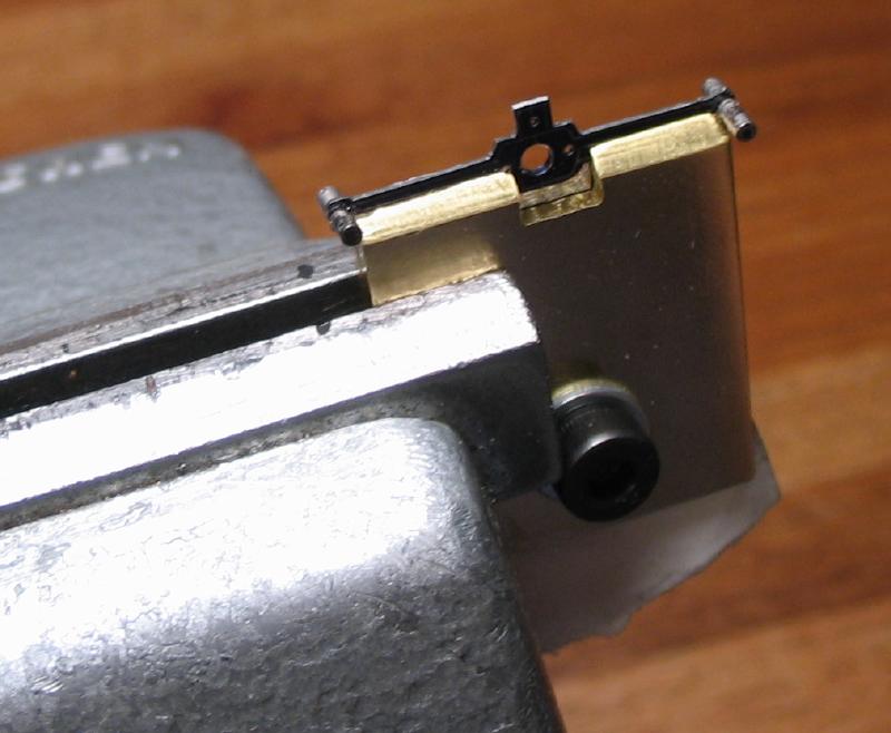
The carriage can be test fit to the movement. A new bridge was made, as the previous one did not provide a great fit and its aesthetics left something to be desired. Shown is the new bridge with a good fit to the carriage, spins smoothly with minimal endshake. The carriage can also be mounted in the calipers to test the uprightness of its rotation axis.
A holding clamp was made from brass plate with a cutout to hold the top plate and top pivot flange (or anything else) while filing the delicate shape.
The top pivot flange was filed on each side to a final width of about 3.5mm. The thickness of the flange happens to be about the same as a piece of masking tape folded over, this was tucked into the bottom of the clamp to even out the clamping forces on the part. The clamp was held in the Palmgren vise, and a comfortable angle found to file. A No. 4 barrette escapement file followed by a No. 6 was used. The same No. 6 barrette file was used to lightly bevel the edges and remove any burs.
The pivot could then be hardened and tempered to blue. The pivot is stoned with a Norton HF-833 hard Arkansas stone followed by the Vallorbe burnisher. This work is carried out on the Jacot attachment. The locating post is turned down to about 0.1mm in length, it needs to be short as possible to provide space for the jewel settings in the carriage bridge, but have sufficient material to provide a means of locating the pivot flange in the bridge and assure it correct position. Once close, I finished the length using the screwhead polishing jig and monitored with a thickness gauge: It was given a final polish.
 |
 |
The top plate can be reduced to its final shape. The layout is scribed onto the plate. A random radius is set on the compass, and arcs are made from each screw position onto the plate. This provides a means of scribing a center line. The top pivot is put into place and the outline traced. The plate is held by the waste portions while sawing out to prevent distortion to the bridge.
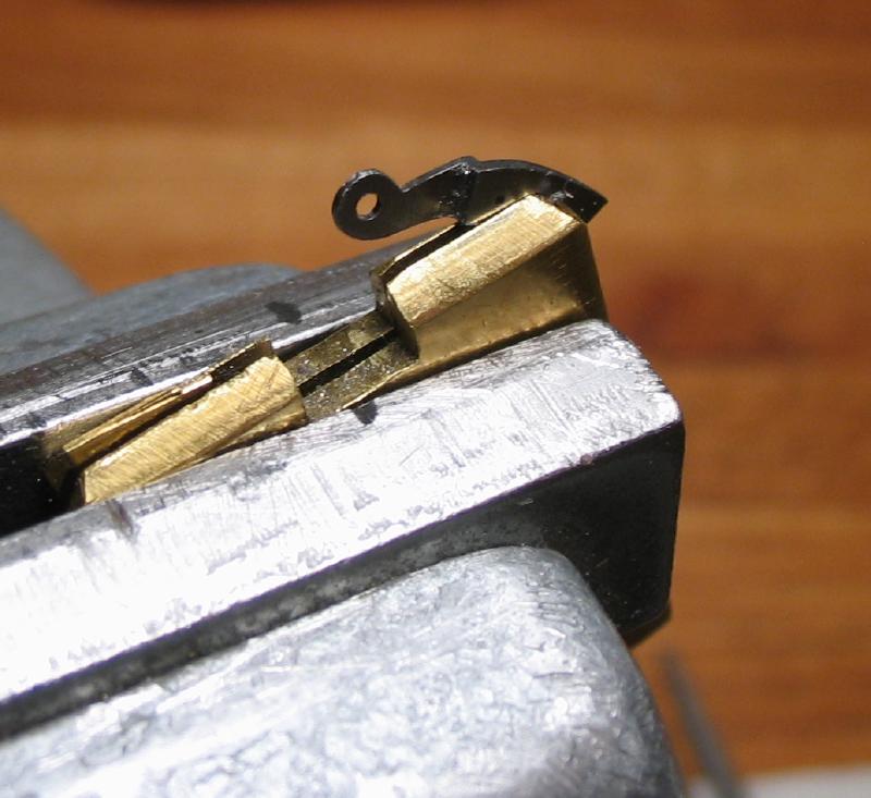
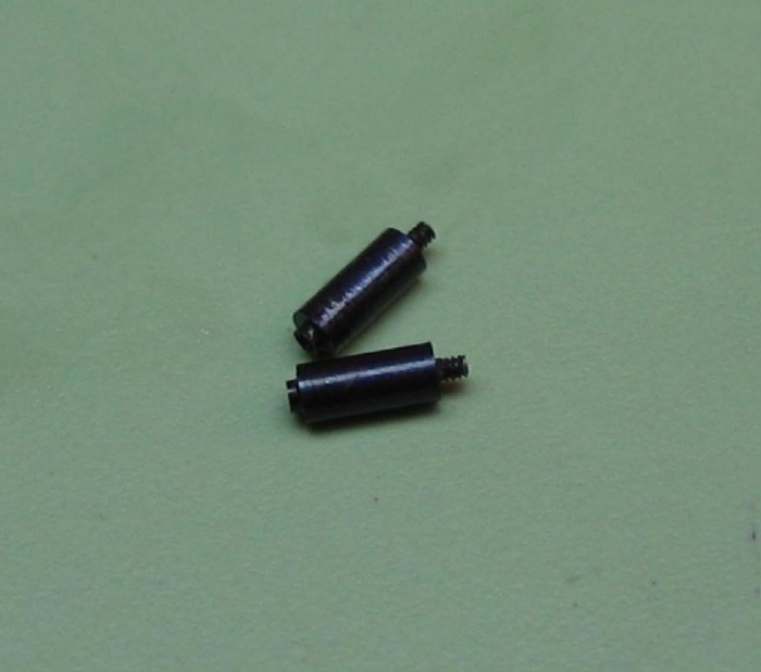
Safety plugs were made for the carriage arm, just as was done with the tourbillon bridge. They are turned from 2mm O-1 drill rod and fully hardened in oil.
Some photos at various stages of filing to shape. Filing was done with No. 6 Escapement files. A square file with safety edge is quite handy at getting into corners.
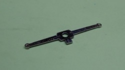
After bringing the bridge to its final shape, it must be checked for uprightness with the lower pillar plate. The bridge is quite delicate and distortion is possible during the sawing and filing process. The pillar plate is setup on the faceplate and centered with the wobble stick to be quite true. The bridge is screwed into position and the truth checked with the wobble stick. Eccentricity which is 90 degrees to the pillar radius can be corrected by gentle adjustment to the bridge.
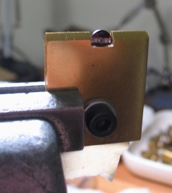
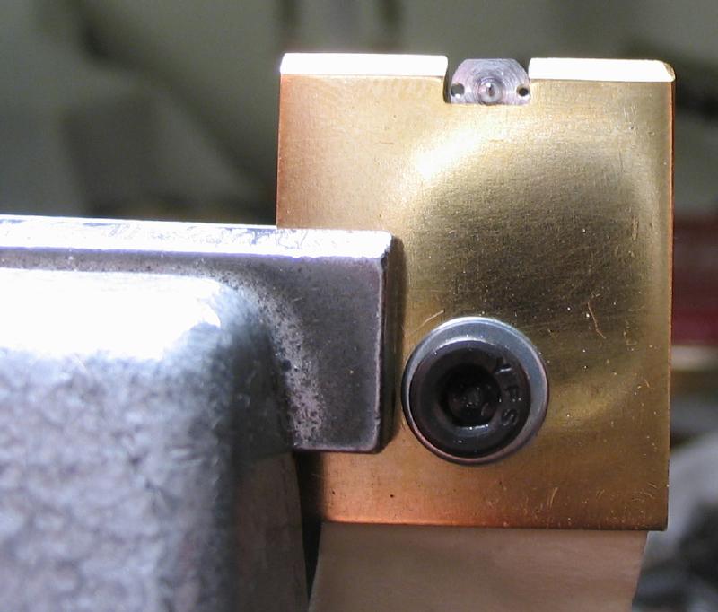
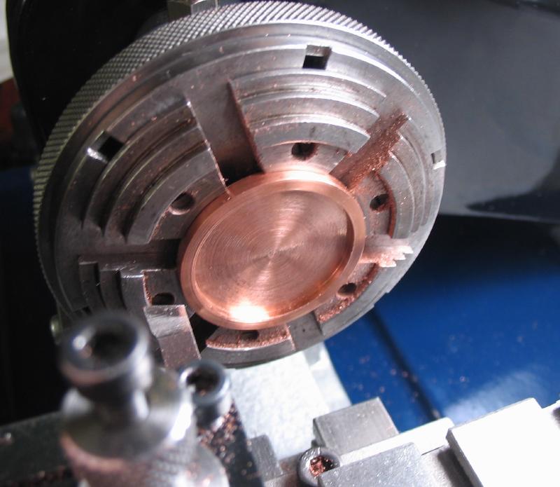
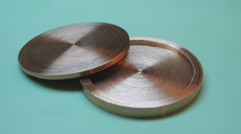
The bridge can now be hardened. The bridge must be protected from distortion during the heating and rapid cooling. The method suggested by Daniels is a copper case (figure 582 and 583, and figure 64 as well). A section of 1.25" copper rod (C145) was parted off. The parted discs were faced using the 6-jaw chuck. They were bored out to approximately 27mm to fit the tourbillon bridge and pillar plate (separately, of course). As you can see from the surface finish, the copper does not machine very well.

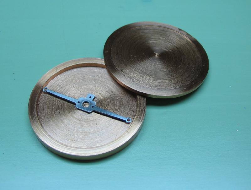
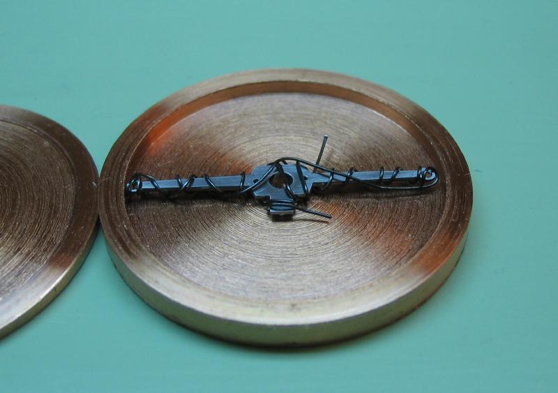
The bridge is loosely wrapped in fine iron wire to prevent the bridge from coming into direct contact with the copper case. The copper case is closed and wrapped in heavier gauge iron wire and a handle formed. The suspended case is heated with a torch to bright red and cooled in a substantial quantity of water. Daniels recommends cooling in water to minimize the quenching time and account for the delay caused by the case. In retrospect, it may have been advisable to use a water hardening steel for the fabrication of the carriage as well. To achieve the required temperature, a plumber's propane torch was used.
The hardened bridge was lightly polished to present a surface for observing color change. It was tempered on a brass plate, drilled to accept the jewel boss. It was tempered to a pale blue. As Daniels points out, hardness is not required for the carriage, and the pale blue state will provide just enough elasticity to be resistant to deformation.
The bridge can then be given its final polish. Beginning with Degussit stones, and finished with fine emery on wood.

Fitting the Escape Wheel
The cock total thickness is 1.4mm and the potence is 1.45mm. These were started from 1/16" O-1 gauge plate. Sections were sawed out and faced down, and lapped smooth to the correct thicknesses. Screws were made to retain the cock and potence to the plate, 0.8mm and 0.6mm, respectively.
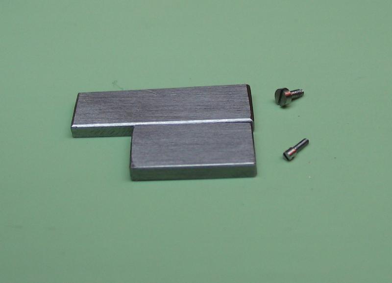
The screws were made in the usual manner, turned, threaded with a die and parted off, however, they were slotted using jewellers slitting saws. The screws were held in the dividing head on the vertical slide and positioned perpendicular to the headstock axis, the saw held on an arbor in the headstock. This method makes screwhead slotting quite a bit easier than with a screwhead flle, especially for these small screws.
 |
 |
 |
 |
The location for the cock screw is laid out onto the pillar plate. It is drilled and tapped 0.8mm. A clearing hole is drilled into the cock, and it can then be mounted onto the pillar plate. With the cock aligned and the screw tightened, the hole for the first steady pin is drilled (0.4mm). The hole in the cock is broached to fit a brass taper pin and with the pin tapped in place, the hole in the plate broached to give a tight fit. Again the cock is screwed in place and the position for the second steady pin drilled, and the process of fitting a taper pin repeated.

The cock is drilled at the escape wheel center position by drilling through the hole in the pillar plate using the same size drill. The cock can then be removed from the plate, and the steady pins removed. The foot of the cock is formed by filing to a thickness of 0.6mm and the table formed by filing to 0.4mm. The shape is kept rectangular at this point to provide rigidity in the boring operations that are to follow later on.
The location of the potence is confined to the space between the fourth wheel and the center wheel, as it operates in the same plane. These radii are scribed onto the plate so that they are not neglected. Note that the potence jewel and surrounding metal will operate below the fourth wheel teeth, one can see that the hole position is close to the fourth wheel circle (the pinion diameter is quite small).
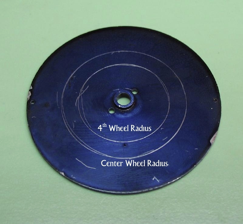
Although the escape wheel is located on the top of the plate, its outline was scribed for reference. The potence will be planted within these confines.

The plate is drilled and tapped 0.6mm, and the potence blank is drilled to pass the 0.6mm screw. The potence is then secured to the plate.

The circles are transferred to the potence, and steady pin locations laid out and drilled, and broached to fit.
The escape wheel position is drilled through the potence.
The potence table is filed to 0.4mm and the foot to 0.5mm. The cock and potence are ready for uprighting.

The potence is attached to the pillar plate, the plate then mounted on the faceplate of the lathe, centering with the wobble stick at the escape wheel position.

The escape wheel hole is drilled open to access the potence.
The hole is bored open to the maximum diameter possible, without fouling the potence.
The potence is drilled 0.9mm
The potence is then bored to 1.10mm, a test gauge was made prior to beginning work.

The potence is then reamed to 1.18mm using a jewelling broach.
The cock is now attached and the process repeated.
The cock is drilled 0.9mm
The cock is bored to 1.10mm, the bore gauge is used to monitor progress.

The cock is reamed 1.18mm with a jewel broach.
The jewel positions in the cock and potence are now accurately aligned and upright. They are to be fit with brass bouchons, and the upright drilling/boring/broaching process repeated to fit the jewels. However, the final shape can now be given to the cock and potence, and then hardened and tempered.
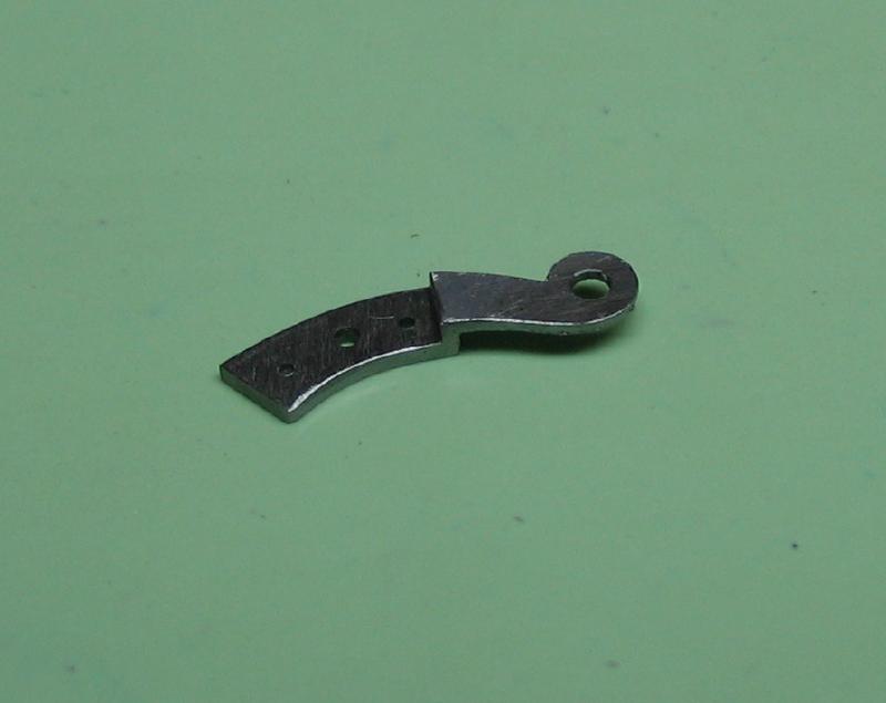
 Cock |
 Potence |
The cock is shaped by filing.