Bezel-Forming Tool
The watch case will be primarily composed of three bands of metal, which include a central band and two bezels. A manual technique of forming these bands is by starting with flat strips of metal (e.g. gold or silver), forming into a ring, and soldering closed. The ring is then made circular and brought to size. The bezel rings must also be formed to their angled shape. These shaping steps are carried out using a special forming tool. Daniels provides drawings of this tool ("Watchmaking" figures 675 & 676) and explains its use. This sort of tool is also described by Steffen Pahlow in his book, and is demonstrated in the video of Martin Matthew on case-making. Despite the apparent, universal acceptance of this tool, I have not been able to locate an example of one in either new or used condition. Although small versions of this type of tool are commonly used by jewelers for making bezel shapes, I am unable to find one that even approaches the size needed for making a bezel large enough for a pocket watch case.
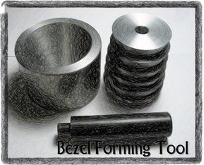
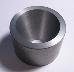
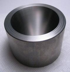
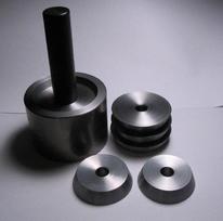
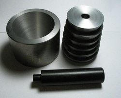
The primary component of the tool, which I am referring to as the anvil, was made from a length of 3" cold rolled steel rod (type 1018) that is somewhat larger in diameter than the diameter of the case itself. Being that a substantial amount of force will be applied during the forming process, a large piece of steel is to be preferred. The anvil is given a tapered bore that will be used to bring the case bands to their final diameter and shape as they are forced into it. From a drawing, I concluded that a taper of about 20 degrees will give a bezel shape that is suitable for the watch described on this website.
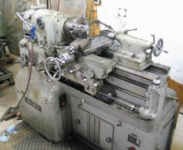
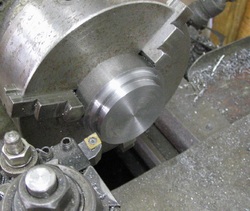
The size of the anvil is much too large to be turned on my Cowells lathe. However, as serendipity would have it, the proprietor of a local machine shop permitted me to log some time on his 1953 Monarch 10EE lathe to carry out this project. Being that the Cowells was the only lathe I had ever used up to this point, the Monarch was a fairly intimidating machine at first, however, once I understood the function of each of the seemingly countless levers, I found it to be quite a pleasure to use!
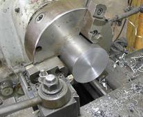
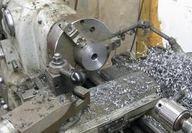
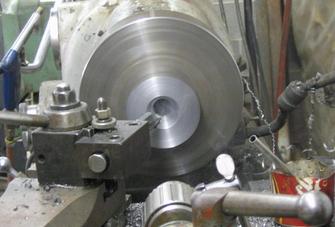
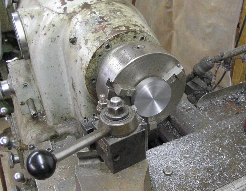
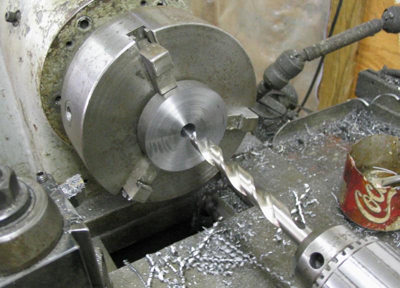
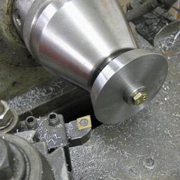
The 3" length of 3" diameter steel rod was mounted in a 3-jaw chuck and faced on either side. A central hole was drilled by a succession of several drills until the boring bar could be easily passed (it can be seen in the photo that I started to continue with an even larger drill, but then realized the hole was quite large enough already).
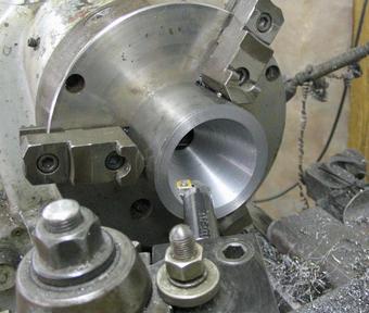
The tapered bore was turned using the compound slide set over to 20 degrees and a fairly substantial sized boring bar installed. The final passes of the boring bar were made light to give it a reasonably fine finish, however, the surface was later improved with various grades of emery paper while slowly spinning the anvil on the lathe, finishing with 800 grit.
Finally, the corners were given a light chamfer using the compound slide to remove sharp edges.
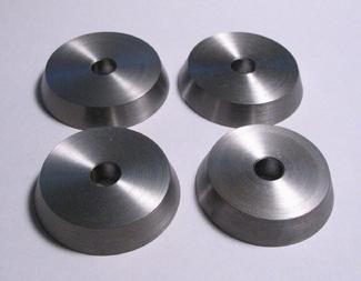
The second component of this tool is a set of tapered discs that match the taper of the anvil. --- Daniels describes and depicts the discs as being tapered. However, in retrospect, the discs do not necessarily need to be tapered and I think this is intended to provide two effective diameters per disc. --- The discs were made in gradually decreasing diameters, and I chose steps of 0.1 inches in diameter. During use, as the bezel is driven into the anvil, the disc will bind on the anvil and a smaller one can be exchanged to continue the work.
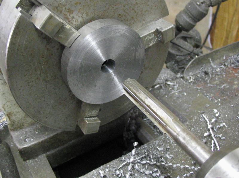
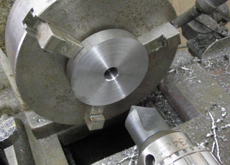
The discs were started by sawing off 1/2" thick sections of 2-3/4" diameter steel rod (type 12L14) - The choice between 1018 and 12L14 steel in making the anvil and discs was based simply on availability at the time. A disc was mounted in a 3-jaw chuck and faced on either side. A central hole was formed by drilling 12.5mm and then reaming to 1/2". The holes were then countersunk on either side to remove burrs.
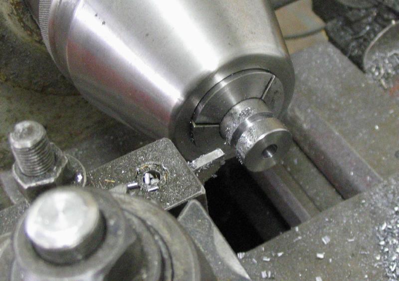
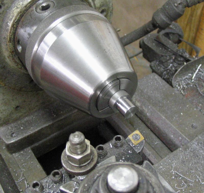
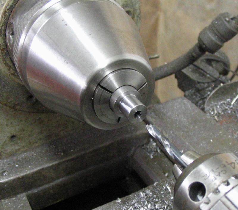
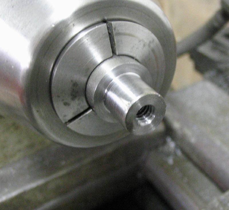
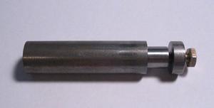
In order to machine the tapered, outer diameter of the discs an arbor needed to be made to hold them. A length of 3/4" cold-rolled steel rod was mounted in a suitable 5C collet. It was first drilled 1/4", and a washer formed by parting off at a thickness of about 1/4". The rod was reversed in the collet and turned down to 1/2" for about 11mm. The rod was drilled with a No. 7 drill and then tapped 1/4"-20. A stock hex head bolt with 1/4"-20 threads was used to finish the work-holding arbor.
A disc can then be mounted on the arbor and a 20 degree taper turned using the compound slide and monitoring the progress of the large diameter for each disc. I made six sizes that should cover my immediate needs, however, the anvil bore goes down to about 25mm, and discs can be made to suit should the need arise.
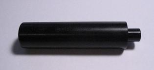
A ram was made from a length of 1 inch diameter Delrin (acetal) rod. The ends were faced and one end given a slight chamfer and the other given a 1/2 inch boss to fit the disc bores.
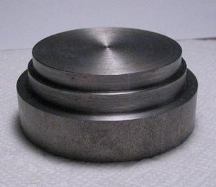
A fairly simple forming tool was made to assist in shaping the bands of metal prior to soldering together and forming them with the tool made above. This tool consists simply of plain diameters that match the desired starting internal diameters of the case band and bezels. A 56mm diameter step was turned onto a short length of 2-3/4" cold-rolled steel (12L14). This diameter matches the internal diameter of the central band of the case, and has a second step was turned to the diameter need to start the bezel rings (~60mm). The steps are, of course, made wide enough to accommodate the respective silver wire stock with some clearance.
