Headstock Casting № 239
Made in 2007
Introduction
If you are reading this, you likely have been or will be confronted with the notion to acquire a lathe. In the watchmaker's workshop, the lathe is arguably the most critical piece of equipment, being that every component of a watch is made on or, at least, at some point influenced by it. Choosing the 'right' machine was not a simple decision. Internet forum threads periodically feature the futile debate about which is the "best" or "ideal", and I have faithfully read them, nay, even studied them. The conclusions can usually be summarized by 'what, exactly, does one plan to do with it' and 'how much money does one have to spend'. Recommendations also include second-hand equipment, and if I was more knowledgeable and/or experienced with what exactly to look for, how to repair / refurbish such machines, and/or personally knew someone who had such tools for sale, I may have pursued this route. However, I will quote George Daniels who on more than one occasion has referred to second-hand lathes as 'false economy' and 'foolhard[y],' and personally I can not say I have had much fortune with second-hand tools.
Being that I did not personally know anyone who owns a lathe, let alone a watchmakers lathe, that I could have 'tried out,' my recourse was to study the available literature, the work of others and the sort of machines they use, compare and contrast the specifications of the available machines and their accessories (i.e. decipher advertisements, etc.). After countless hours of consideration over the last couple years, I finally reached a decision as to what sort of machine I would need, want, and ultimately purchase. My complete rationale is beyond the scope of this article, I am not sure I could recall or put it all into words, and as basic psychology would remind you, rationales are always better defended after having committed to them. Suffice it to say that I resolved to purchase the Cowells 90 CW and it seemed to resonate well with the criteria I had formed in making my decision. It cost more than I had originally hoped; however, my experience (especially with tools) is that one usually gets what one pays for. In addition, the higher cost was partially due to a rather weak dollar compared to pound sterling (a 26 year low to be more explicit), and both my bank (~3%) and my government (~4%) taking a percentage of the transaction. I did, however, find some equanimity in that the Cowells was not the most expensive lathe I considered.
“The best is the cheapest in the end ... quality will remain long after the price is forgotten” - Sir Henry Royce
The arrival of this machine marks an important turning point (pun not originally intended) in my capabilities in the workshop, and the innumerable utterances of "… if I only had a lathe …" shall no longer be a viable excuse, and judging from others, will be replaced by, "… if I only had more time …"
Cowells Small Machine Tools LTD
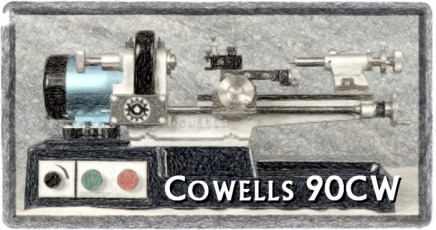
For those who are unfamiliar with Cowells, they are small company located near Cholchester, England. The company was established in 1975. Their machines are hand built, to order, by an experienced tool room engineer. They produce several different machines, including a model engineer lathe (90ME), a clock and watchmakers lathe (90CW), a vertical milling machine, and a jigsaw. I think the phrase 'for craftsmen by craftsmen' would describe the general attitude of the company. In the realm of haute horologie the subject of whether the components are produced 'in-house' is often discussed/debated. At Cowells, all parts of their lathes are made in England, however, about 80% of these components are made by local contract machine shops. The remaining 20% and all assembly and alignment work is performed in-house. In my opinion, and the same applies to watches, whether the part is made in-house or out-of-house doesn't seem to be as nearly as important as how well the part is made. From what I have seen, no concessions have been made and quality remains their first priority.
Colin Childs, the director at Cowells and the one with whom you are likely to speak to when contacting them, was very helpful with all of my questions and always prompt in his responses (even when asking annoying questions, such as 'how much is made in-house?'....). I have a tendency to over-think small details and looking through my email inbox, I found emails dating back to early 2003 regarding things like collet dimensions/interchangeability and such, how much I have learned since then! This experience was in stark contrast to that of some other manufacturers, who would never respond (perhaps because I do not speak French or German), would send me a brochure, or simply refer me to their distributor, who couldn't tell me much more than the current price. This ease of communication was certainly a factor in my decision, even if it was only a subconscious one. I placed my order and was given about a four month time frame for delivery (turned out to be about 4 ½), which only seemed like a long time, since I had put it off for so long already! Considering that their machines are built to order and to the buyers' specifications, in reality that is not long at all, and this gave me time to figure out what else I needed for its arrival (various metal stock, cutting tools, etc). I tried to keep the initial cost to a minimum, choosing only the accessories I thought were "critical," but quickly observed from my 'wish list' tally that frugality wasn't going to be the case.
For a historical account, a website dedicated to information about lathes (lathes.co.uk) states that the original Cowells lathe can be traced back to a lathe maker in Sheffield called Flexispeed, made in the 1940's. The Flexispeed was manufactured for about 30 years, changing ownership several times. The names were changed to Simat 101, Meteor, Hector, Norfolk, and finally Perris. According to the article in Model Mechanics (1979, click to read article) Brian Perris passed suddenly, ending the Perris lathe. Sid Cowell purchased the company and began making the first Cowells lathe which was based on the Perris SL90, almost unaltered. Cowells have since refined the machine to its current state, and produced more specialized variations to the basic machine, e.g. the 90CW and the no longer produced, 90HS.
I was kindly provided the construction manual to the Perris SL90 lathe kit by an owner of one of these machines. A scan of this manual can be found in the following link.
| cowells_90_review_from_model_mechanics_feb_1979.pdf | |
| File Size: | 798 kb |
| File Type: | |
| Perris Lathe Construction Manual | |
| File Size: | 4092 kb |
| File Type: | |
Also, for anyone who may be interested, I was provided with a copy of a brochure for the Cowells tool lineup from the late 1970's. The owner of the document deduced that from the format of the telephone number and address that it was likely from that time period.
| Cowells Brochure 1970s | |
| File Size: | 1938 kb |
| File Type: | |
The Arrival
Keeping in line with the aforementioned 'new watch' posts, I have documented the arrival of my new prized possession. I am not much of a photog, but I will try to capture its likeness, and hopefully not seem like the proverbial 'mule with a spinning wheel' [i.e., nobody knew how he got it, and dang if he knew how to use it].
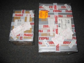
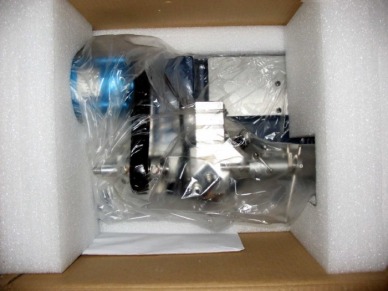
After settling up with the brown-shirts who required Uncle Sam's ransom for this purchase (subtly referred to as the harmonization tariff), we can see here the two, rather hefty cartons, resting quietly after their nearly 4000-mile journey from Cholchester, England to Maryland.
'Thinking outside of the box'
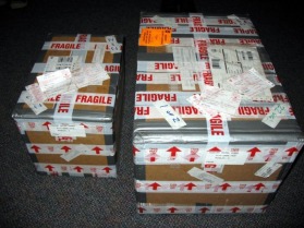
The boxes were very securely packed, and as you can plainly see, tried to express the idea that the items within were fragile, but that apparently didn't phase the UPS clerk, who rounded the corner at the pickup facility pushing the box along with her foot ...
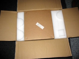
Digging in....
Ahhh, hard to believe it is sitting here before me, after all the time spent imagining it!
Taking a look - Piece-by-Piece
The lathe itself: Although unavoidable, I will try not to write this as an advertisement, and I will refer you to the Cowells website for a full listing of all the features of this machine.
Their current brochure (2009)
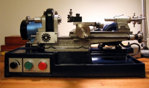
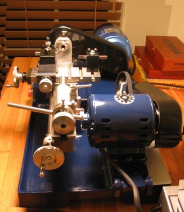
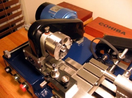
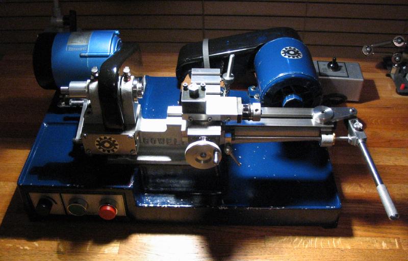
My first impression is the solid feel of the machine; it definitely does not feel like a toy. As with most things, photographs just don't seem to do them justice, the fit and finish of the components remind me of those of a watch movement. You can see that with exception to the fiberglass belt guards and cast aluminum base, it is made almost entirely of cast iron and steel. The cantilever style bed has a large footing directly under that portion where most of the 'action' takes place. The bed is dovetailed and T-slotted, and has a built-in gap (60mm center height) which was an important feature for my requirements. I anticipate that the gap should allow the turning of larger diameter parts, such as clock wheels, pocket watch movement plates and cases, etc.
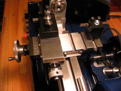
The lathe uses a long, ground cast iron cross slide. It has 3 T-slots which are the fixture point for many of the lathe's accessories. It has a topslide which is pivoted with etched angular markings. The stainless steel handwheels are large for fine adjustments and have a small knob for more rapid advancement. The laser etched dials are clearly (white on black) graduated to 0.02mm and are resettable to zero.
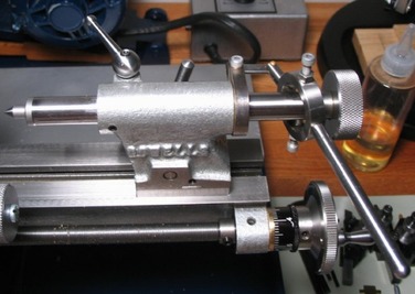
The tailstock is collet holding, is offset-able, and has a simple lever feed for sensitive drilling.
The headstock and mill spindle (described below) use conical phosphor-bronze bearings with a hardened and ground steel rear bearing that has an adjustment nut for elimination of any 'end-float'. You can see the oil reservoirs on the headstock, and Cowells recommend Myford Nuto oil. The oil reservoirs are made by Adams of Coventry (see brochure below).
The subject of spindle oil in the machinist forums seems to be another debated subject. A little research reveals that Myford Nuto is Esso (or Exxon here in the U.S.) Nuto H32 hydraulic mineral oil, which has a ISO viscosity grade of 32, and is equivalent to various other brands, Angler Accuvis 32, Castrol Hyspin AW32, Mobil DTE 24, Texaco Rando HD32, Shell Tellus 32, Sun Sunvis 32, and Fuchs Renolin AW32. A critical point, from searching the internet, is that the oil be detergent free, since these can hold moisture and therefore promote oxidation. Unlike many motor oils, hydraulic oil is detergent free with some additional anti-oxidants with mineral oil base. I ordered a half liter of Myford Nuto from Blue Ridge Machinery in West Virginia, with shipping it cost $20, and I could have bought a gallon of Mobil DTE 24 for the same price.
Generally speaking, I ordered the standard CW model, threaded for Schaublin B8, however I requested a carriage leadscrew in place of the lever feed. The lever can be added or swapped later on, and I imagine is advantageous for wheel cutting, but for the time being, I decided to have the graduated feed of a screw and dial.
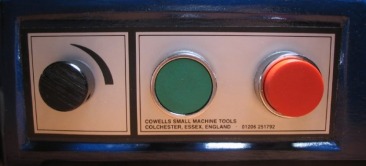
For the 90CW model, Cowells uses a D.C., shunt-wound, 1/6HP Parvalux SD11 motor with a DC thyristor for speed control. At full load (125W) it is capable of 4000 RPM. D.C. motors produce their maximum torque at start-up and low speed, and an electronic control makes belt and pulley changing virtually unnecessary, providing full, useable control over the entire speed range with just the turn of a dial. Parvalux, located in Dorset, seem to have a good reputation for their motors, they don't come cheaply either. I inquired out of curiosity, and Parvalux quoted me about US$ 350 for the motor, without the controller circuit.
| Adams (Coventry) Oil Reservoirs | |
| File Size: | 3426 kb |
| File Type: | |
The file below contains the pages from the Parvalux catalog that apply to the SD11 motor.
| Parvalux SD11 | |
| File Size: | 389 kb |
| File Type: | |
The main drive belt from the Parvalux to the headstock is the 400mm vee type belt, it does not have a manufacturer name, but is labeled MB-400. A similar belt is used on the wheel and pinion cutter, however is MB-410 (410mm circumference).
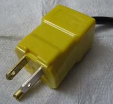
| Hubbell Valise | |
| File Size: | 2950 kb |
| File Type: | |
Cowells perform an accuracy examination of each lathe prior to delivery and issue a numbered test certificate with the results. You can see from the scan that the run-out is typically about 0.005mm (0.0002"). I have read that this is the specified TIR for the Schaublin 70 lathe. To contrast, Levin currently specifies 0.00005" (0.001mm) for their high-accuracy model (I could not find the specification for their standard model), and Derbyshire reports the same for their Magnus Instrument lathe. Considering, among other things, that the specified tolerance of my Schaublin B8 collets is 0.01mm, it would seem to me that being too critical about T.I.R. can only go so far, and that those of the Cowells should meet my needs.
| Test Certificate | |
| File Size: | 888 kb |
| File Type: | |
While considering the various lathes on the market, I located a copy of Andrew Smith's book on using the Cowells 90. A slightly updated and spiral bound copy of this book is included as part of the lathe's care & use package. The book itself, is really meant for the 90ME lathe, and for the complete novice-machinist is a useful text, but not for horological instruction.
Cowells also includes a set of type written (and well photocopied instructions), which describe the basic care, maintenance and use of the Cowells lathe.
| Cowells Manuals | |
| File Size: | 2655 kb |
| File Type: | |
Horizontal milling attachment: a.k.a. 'the Wheel and Pinion Cutter'
The current brochure (2009)
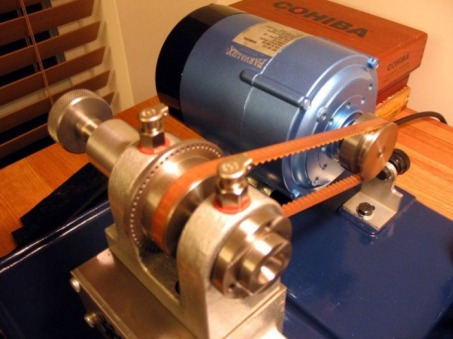
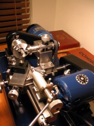
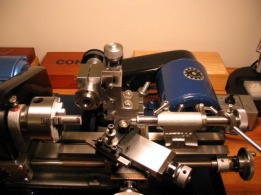
They include a 1/20HP GEC 1725RPM reversible AC motor. It uses a layshaft and pulley setup for speed selection (490, 1100, 2400 RPM). I added the slow speed reduction pulley to provide 300, 690, and 1500. Slower speed combined with the manual lead screw should allow for milling steel watch pinion leaves (my conclusion is based on the recommendations in J. Malcolm Wild's book on this subject). The mill is a rather ingenious setup, bolting directly to a machined surface of the lathe's base with two M6 socket head bolts, and the motor and countershaft assembly is hinged so that its weight provides constant belt tension to the spindle. The layshaft and mill spindle use toothed pulleys and ribbed belts instead of the elastic cord I usually see on watchmaker's-style lathes. The mill spindle mounts to the vertical slide by two T-bolts and accepts 8mm draw-in collets and also has a tapped flange ready to accept the M14x1 chuck adaptor.
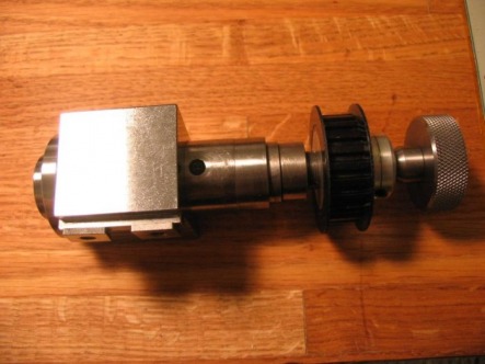
Shown here is the milling spindle, with the actual spindle cartridge withdrawn to expose the oiling port.
The milling spindle pulley is a Davall (England) P22XL037 nylon wheel with aluminum hub (22 teeth, 1.40" pitch diameter). The drive pulley on the layshaft is a Davall P18XL037 (18 teeth, 1.146" pitch diameter). The drive belt from the layshaft to mill spindle is a Contitech (Germany) 170805 (120).
| Davall Classical Pulleys | |
| File Size: | 254 kb |
| File Type: | |
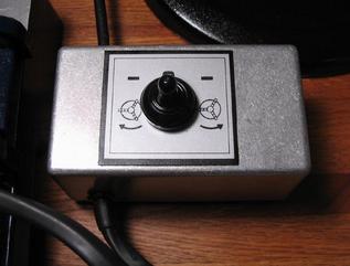
The motor is reversible and is controlled by a switch box. The Deltron enclosure contains the wiring to the DPDT switch and overload relay. (Magnetic Devices Ltd. GEC/311W/G31 - DRG CYI 60232 rev9).
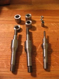
I plan on using P.P. Thornton cutters, so I ordered a pair of collet-shank arbors for the respective Ø7mm and Ø3.5mm wheel and pinion cutter bores (RG71-5 and 6). They are sent "unfinished," for example the actual shaft diameter is 7.5mm, and was therefore finished by myself to the proper 7mm diameter to ensure concentricity for the cutter. The width of the small watch size wheel cutters is much thinner than the larger sizes including the ratchet cutters, so I made a spacer to fit the arbor and take up the extra length. I also made an additional arbor with a 1/4" shaft for other milling cutters (shown in the center), it was made from a collet arbor blank I found on eBay, being an early project I was quite pleased at how well it turned out.
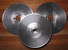
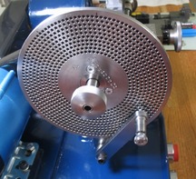
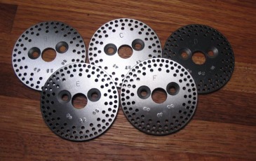
Indexing is accomplished by the use of division plates and a detent. The detent is anchored to the lathe bed by two screws. The Ø 6" plates are made of steel and reamed 1" and attach by three M4 screws to a Ø 0.999" adapter that then screws directly onto a threaded portion of the headstock spindle in place of the bearing adjuster nut and is secured by 2 brass set-screws.
There are five different plates available, however there is redundancy among them. I would suspect that there is some logic to the choice of counts for each plate. I chose plates 2, 3, and 5. Together they provide all counts available, making 1 and 4 unnecessary. For the watch described on this site, all necessary counts are provided on plate 2, except for the third wheel tooth count of 75, which requires plate 3.
RG-G2 120 - 100 - 96 - 90 - 84 - 80 - 78 - 72 - 64 - 62
RG-G3 88 - 75 - 70 - 63 - 59 - 56 - 54 - 49 - 41 - 34
RG-G5 144 - 132 - 118 - 114 - 112 - 108 - 98 - 74 - 70 - 58
RG-G1 100 - 96 - 84 - 80 - 78 - 72 - 64 - 62 - 60 - 59
RG-G4 144 - 120 - 114 - 112 - 100 - 96 - 84 - 70
Advantageous for rigidity in wheel and pinion cutting, the mill spindle is always set perpendicular to the headstock, however, this does present a minor draw back. The spindle itself can be set to be parallel to the headstock, but not the motor and pulley assembly. So to use the mill spindle for off-center drilling (e.g. lantern pinions or any number of other similar tasks), I will need to rig up some sort of alternate drive system. Cowells recommends using their dividing head attachment for these sorts of tasks, instead of what I am describing, so I can't really fault their design.
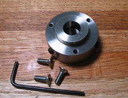
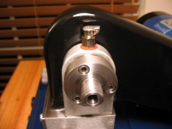
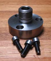
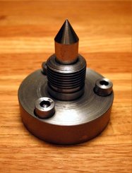
The G13 chuck adapter is another interesting Cowells creation. Since their 90ME lathe has a 14mm threaded spindle nose, they created this adapter, that mounts by three M4 screws to a flange surrounding the collet spigot on the 90CW, it enables one to use the same 3 and 4 jaw chucks and faceplates on either machine. In the past they offered a collet-shanked adapter, just as you would find on standard watchmakers' lathes, but Cowells has determined that the current arrangement is much more rigid and accurate than the former. However, they still offer the collet-shank with M14 mount for sale.
I had them ream the adapter to a zero Morse taper, so that I can also use the R29 0MT center. My thought here was to be able to rig the faceplate as a driver for center turning large arbors, pillars and such.
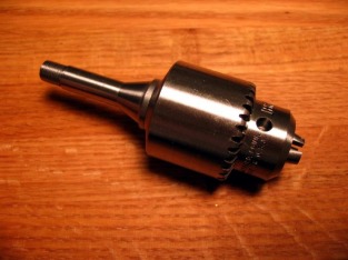
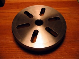
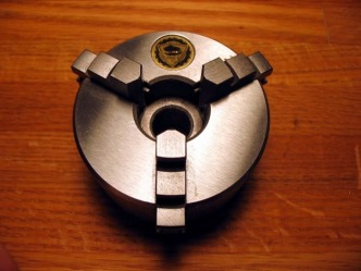
Chucks: I ordered the RG28 faceplate and the RGB15 ¼" drill chuck on a collet arbor, I already had a Jacobs chuck to fit the arbor, but they added one at the same price, Colin wanted to ensure that it ran true on the lathe before sending it out (a reminder of their desire to ensure precision). I didn't ask where Cowells obtain their 3-Jaw chucks, in the past they used Pratt-Burnerd and more recently Toyo (i.e. Proxxon). Their current chuck looks identical to the Bison model 7-810-0214(see page 70). Since the Bison chuck is available here in the States for almost half the cost, I opted for it early on in my decision, hopefully I won't regret it.
| Bison Catalog 3-jaw Chuck | |
| File Size: | 177 kb |
| File Type: | |
I ordered the RG53 double roller filing rest, it is backordered for the time being. Update (Feb, 2008) After several months of waiting, due to a missing component which is made by one of their contract machine shops, the filing rest has arrived. I am again quite satisfied with a well made, uniquely designed tool. The rest is fit to a shaft which attaches by a screw onto the headstock-side of the cross slide carriage, this keeps the rest on center and allows vertical movement. It is mated to a block with an angled keyway which is mounted in a T-slot of the cross-slide. As the cross-slide is fed in or out it raises and lowers the height of the rollers, which can be arrived at by trigonometry. As usual it is constructed entirely of steel, and the rollers are hardened, and not being polished, therefore have some discoloration.
Instruction sheet that was provided with the filing rest.
| Roller Filing Rest Instructions | |
| File Size: | 42 kb |
| File Type: | |
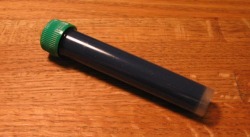
With the filing rest delivery I had inquired about some touch-up paint for the lathe base, which I had put some chips in while fumbling with wrenches and chuck keys. They kindly sent me a small vial of matching paint, free of charge. Since inquiring about the paint I had become less concerned with such details, which are the inevitable result of using something (at least for klutzes like myself). I should have transferred the paint to a more air tight vial, it has subsequently dried up ...
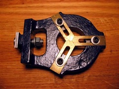
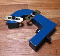
For turning longer lengths of material a means of support is required. Two options, which depend on the project at hand, are the fixed steady rest and the traveling steady rest. The fixed version (RG39) attaches to the lathe bed and has three adjustable brass fingers for holding round stock. The traveling steady rest (RG40) attaches to the cross slide carriage and has two fingers which support the work and resist the pressure from the cutting tool, and being attached to the carriage, it 'travels' with the cutting tool.
The tailstock drill pad (RG38A) has a collet type shank for mounting in the tailstock quill and has a milled vee for supporting round stock for cross drilling, etc. Of course it can be used for general drilling jobs and the tailstock lever is used to advance the work.
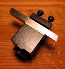
Shown is the rear tool post for cut-off tools (RG41). It is mounted in one of the cross slide T-slots and the cut-off tool is mounted upside down since the cutting action is in the opposite direction. It holds 1/4" lathe tooling, same as the topslide toolpost.
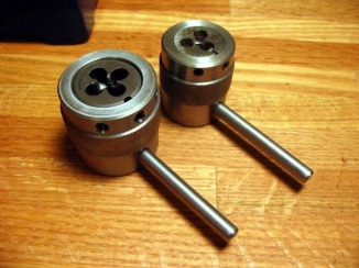
The die holders (RG46 and RG47) are bored to fit onto the tailstock quill and have a removable tommy bar. Each is recessed to accept either Ø 13/16" or Ø 1" dies.
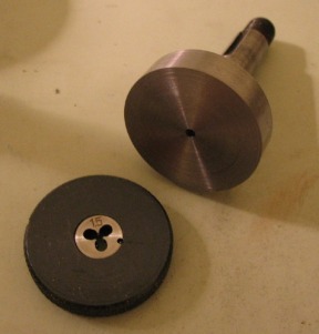
Unfortunately the O.D. of Bergeon watchmaker dies are Ø 8mm so these die holders are not useful for them, however I have the Bergeon hand-held die holder. These small dies require a very delicate application. I have experimented using pot chuck blank which has been faced and drilled to allow the threaded portion of the screw feed into it as it is formed. With light pressure from the tailstock it can be used to maintain 'upright-ness' when using these small dies.
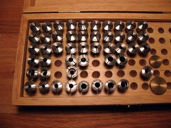
I had picked up a few lathe components in the months leading up to the final commitment to purchasing the Cowells. In retrospect I may have not done so, but one exception is my set of collets. What appeared to be an essentially new set of Schaublin B8 collets came up on Ebay and I purchased them for about US$ 400. Seemed like a lot at the time, but to purchase just the Schaublin collets in this set new would cost about US$ 3500, and I received 8 miscellaneous other collets and a 5mm internally threaded collet with 2 wax chucks as a sort of bonus.
Among the second-hand Cowells items was the vertical slide. It was in decent shape, a little scratched, but otherwise functional. However, the leadscrew thimble was not resettable and was graduated in 0.025mm increments. I was able to replace the leadscrew and thimble with a new one, which is similar to the other leadscrews and dials.
The old screw and dial.
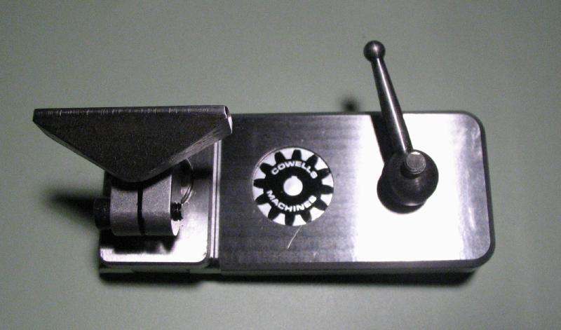
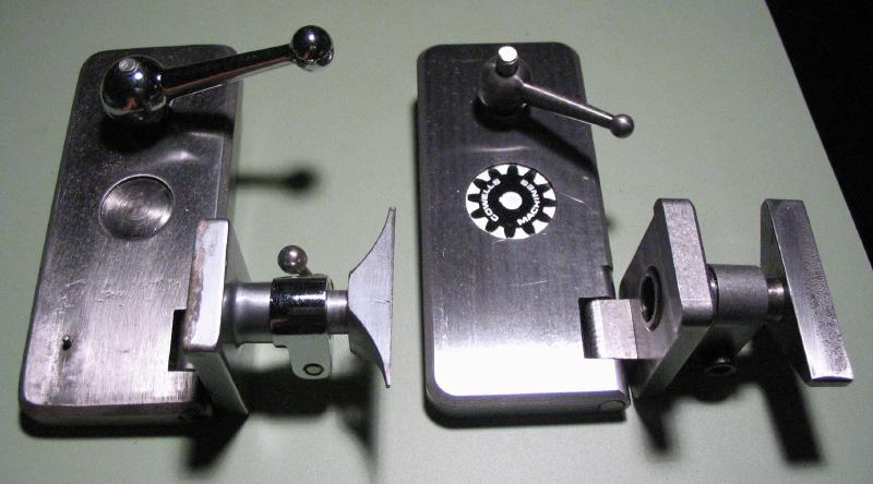
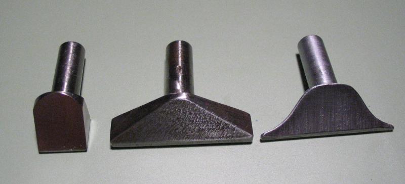
I purchased a Cowells tip-over T-rest (RG58) second hand as well, it's missing the Cowells decal, but what watchmakers lathe could be without a T-rest! I did have some issues with this rest however, as the tip-over portion of the rest had a small amount of side shake to it, which allowed for some movement of the T-rest when using it. I found odd ways to adjust for it, but when hand-turning, one does not need any added difficulties. I acquired a new version of the rest, which differs in that it has a smaller ball handle (the larger version did get in the way at times), the T-rest does not wobble at all and is quite firm, and the actual T-rest is a somewhat more substantially constructed version. The T-rests are shown for comparison along with a smaller one that was made (see turns page).
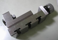
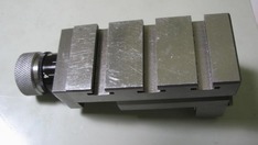
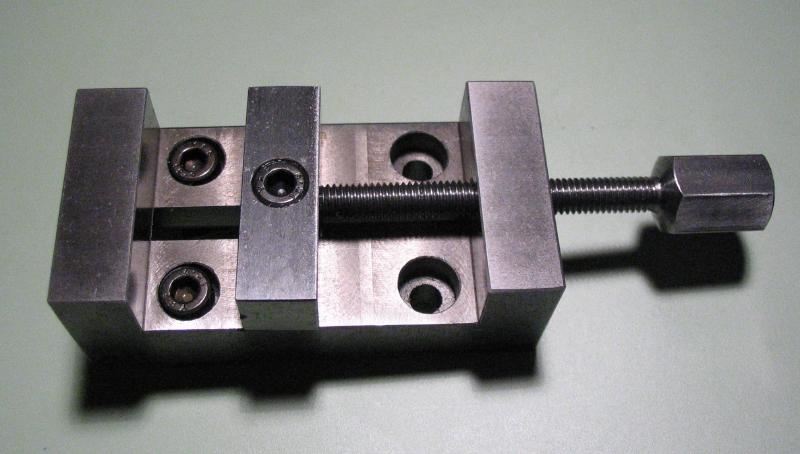
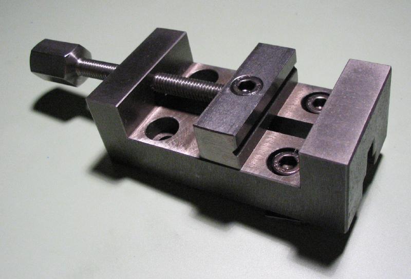
I had found a second hand milling vise (RGB57) that mates with the T-slots of the cross slide or vertical slide of the Cowells lathe (it also works with the table of their vertical mill). Their milling vise has been updated since my version was made. The newer version has a vee-groove to hold round material more securely, and has four T-slot screws positions instead of two (I suspect it is primarily for more secure use on their milling machine), and they are counterbored deep enough for regular socket head screws. The older one was supplied with slotted screws which were not always easy to work with. I had fit a pair socket head screws, however the heads of the screws had to be ground down for clearance.
I picked up what is commonly called a carrier or driving chuck, it is not manufactured by Cowells, but by someone who is apparently a skilled machinist and has good knowledge of what is needed with respect to lathes and expanding their use. It was supplied with an assortment of centers (including 2 male, 2 female, a brass, and one designed for turning wood), a set of dogs, Allen keys, and a wooden stand. It will likely look familiar to those who browse Ebay for watchmaker's lathe-related items, since I believe he made a number of these.
Its New Home
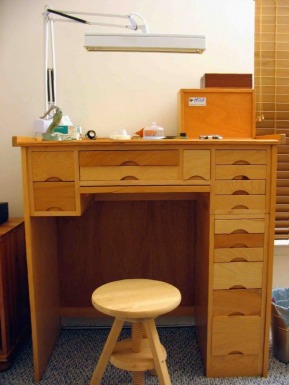
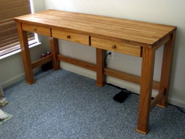
I am fortunate to have a spare room in our house to designate as my 'workshop,' I say fortunate since this hobby started with a cigar box of tools and our tiny kitchen counter in our tiny Philadelphia apartment. I currently have a standard 'watchmaker-style' workbench (made by USA Bench) which has since been designated as the 'clean' bench for disassembly, cleaning and reassembly, etc. of watch movements and similar sorts of tasks. Anticipating the arrival of the lathe I decided a new and larger bench for metalwork was in order. I hired a local cabinetmaker to construct a bench to my relatively simple specifications, a proper height, a length to fit the available wall space, heavy duty as to not wobble about, and made entirely of American red oak (because I like it), a matching mineral oil-finished red oak butcher-block-style top, and of course, it needed to look nice so my wife wouldn't mind seeing it in the house. The final cost was less than my mostly plywood-n-poplar watchmaker's bench, and he made it for about what the lumber would have cost me to make it myself, so I felt it wasn't a bad deal.
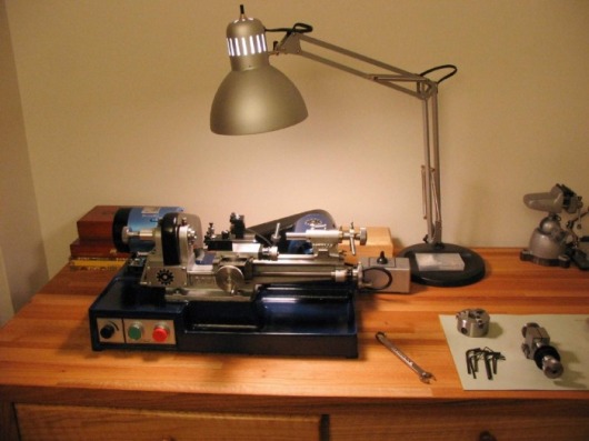
Its new location will be more or less permanent, however all the lathe's components are bolted directed to its cast aluminum base, which has built in handles, and does not need to be fixed to the benchtop. The whole machine can be unplugged and picked up and moved to a new location. The whole unit is heavy enough that it stays in place during use, the lathe without the milling attachments weighs about 50 pounds.
"Watchmakers" Bench
New Machine Bench
Cutting Tools
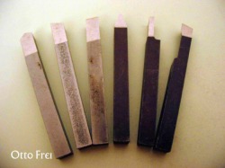
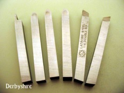
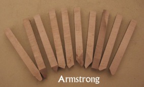
I mentioned earlier that I would need some cutting tools. Cowells does offer 2 different sets of six ¼" cutting tools. For one reason or another, I decided to try and find a domestic source. I can imagine some of the readers are saying, "grind your own", but not having a grinder on hand and I decided to start with a positive control. The first set I came across is made by Armstrong Tools, and is a set of ten assorted ground shapes. Although they do not appear very appealing in the photo, they are well made good quality M2 steel. However, when I received them, I was left a bit confused. All of the cutting faces have either a zero rake or a positive rake. So I was therefore was in search of another set. F.W. Derbyshire listed a set in the literature they had sent me during my lathe research. They are ground from Timken Latrobe Double 6 steel (I assume the 'double 6' refers to their specified 66 Rockwell-hardness). These tool sets were on backorder, and fearing they would not arrive in time, I settled on a set of cutting tools sold by Otto Frei. I don't know where these are made or out of what type of steel. Ironically the Derbyshire set arrived a day before the lathe, and consequently I then had a fairly large collection of ¼" tool bits to start out with.
I'll mention that I later learned that the Armstrong tools are manufactured for use with an "American-style" tool holder, which holds the tool on an angle. Therefore the rake angle is a combination of the ground angle and the held angle.
A Maiden Voyage
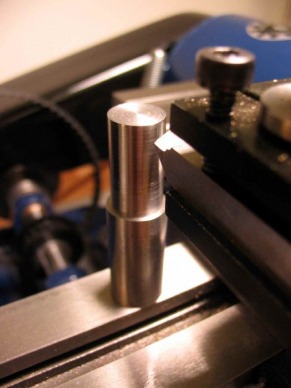
I decided to include in this post my first project with the new machine. Rather than just make swarf, I tried to think of something useful, but relatively easy to make, since it would be my first go at turning. I decided on a tool height setting gauge, a basic tool that is not available as an accessory from Cowells (I suppose this is due to every lathe being ever-so-slightly different, or maybe because it is simple to make from about 25¢ worth of steel rod). As the name implies, it is for setting the cutting tools on center height without the need for putting a 'center' in the head– or tail stock. One can then change tools in the tool post and fix the proper height, in situ, without un-chucking the work. It is equally useful for milling cutters, wheel & pinion cutters, setting-up work in the vice etc. Also, as a first project, it is about the simplest turning exercise you can imagine, and it incorporates a number of basic skills.
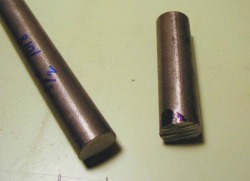
I started by hack-sawing off a section of ½" round - C1018 steel to a length a bit longer (total: 1 - 13/16") than the specified center height of the lathe (1 ¾") and filing the end reasonably smooth. I suppose I could have used brass, which would have been easier to machine, but 'mild' steel is cheaper and I think will be more durable for use as a tool.
After fixing the rod in the 3-Jaw chuck, the end was faced with a standard right hand knife tool, which was already set to height using the male center. This end will become the base of the tool and just to ensure it will always stand true, I decided to form a few thousandths inch recess, so that the tool will actually be standing only on the rim of the base.
The finished end could then be stood on the lathe bed and cross slide, and scribed with their center heights by means of the hardened male center located in the collet-holding tailstock.
The rod could then be turned and faced on the opposite end, down to the bed-to-center scribe. A shoulder was then turned down to the cross slide-to-center height.
You can see the finished tool here, as it would be used to set the correct height of a cutting tool.
As an after thought, it would have been useful if the tool had been turned from hexagonal rod (which I didn't have anyway), so that it wouldn't roll away when knocked over on the bench top.
Other Accessories
As funds/needs permit and I acquire new accessories from Cowells, I will list them here.
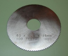
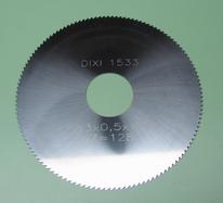
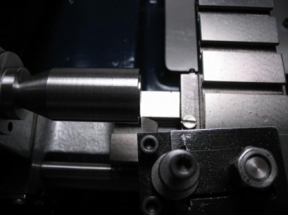
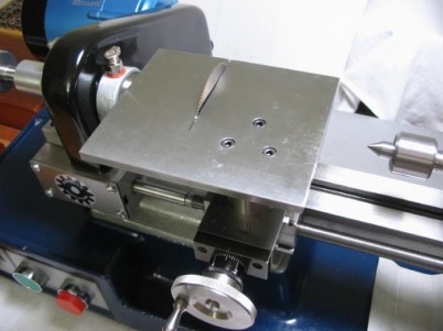
First to make it on this list is the RG51 Slitting Saw attachment. It consists of a steel table that mounts on an adjustable height post which mounts in the top slide hole of the cross slide. The table is slotted to allow a slitting saw to run in it. Although the Cowells website states that the saw arbor mounts to the G13 adaptor, the slitting saws are mounted on a collet type arbor. The HSS saw selection available from Cowells are 63mm in diameter and have a center bore of 16mm. The saws are made by Cardinal in England. The collet shank arbor is provided with a 17.5mm mount and are finished to fit. 16mm bore slitting saws are not a popular size here in the U.S. A nice alternative are Swiss made Dixi carbide saws. They are not easily found here either, but shown is a Model 1533 saw (63mm x 0.5mm x 16mm bore). Of course, a separate arbor can be made to suit whatever size saws. This attachment is useful for general sawing of stock and various other endeavors where a square cut is needed. Mr. Childs recommended the 0.6mm saw as a general purpose saw which maintains good rigidity.
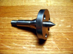
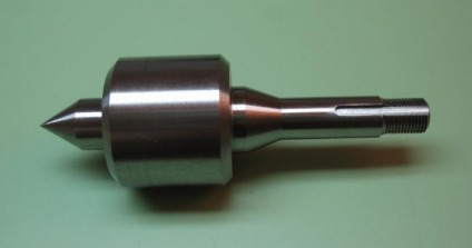
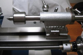
The G36 rotating center (a.k.a. Live center). The live center is mounted in two permanent bearing and is ground for concentricity. Although their website states it has a 6mm shank to fit a 6mm collet in the tailstock, it is, in fact, permanently mounted on a collet shank. A live center is useful for turning with tailstock center support for extended periods of time without the excessive friction or potential wear to the hardened dead center.
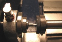
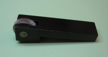
The RG84 Knurling tool. I ordered it with the chequered form wheel. It is an example of the simplest form of knurling tool. I picked it up for adding a knurl or diamond patterned grip to various tool parts that I have in mind.
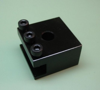
I ordered a simple tool post, the version which is typically supplied with the 90ME lathe. My reasoning is that the quick change tool post overhangs off the topsilde and when turning small parts between centers or turning angles with the topslide it can get in the way, and I sometimes wish I had a little more freedom of movement. My thought is that the shorter simple tool post may help alleviate this.
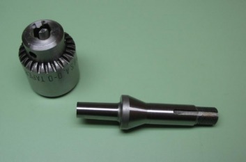
RGB70 collet to Jacobs 0 taper. I already owned a 5/32nd Jacobs chuck with a J0 internal taper. The arbor appears to have been machined or even ground between centers. Accurately mounting the chuck will be the trick. For this, I was told:
"...this can be tricky but not impossible-you would need to mount the arbor in the lathe's headstock and gently wring on the chuck until a known straight diameter runs truly. I have to say that this is not my favourite job either- usually manage to get such a chuck to run within 0.001" TIR however..."
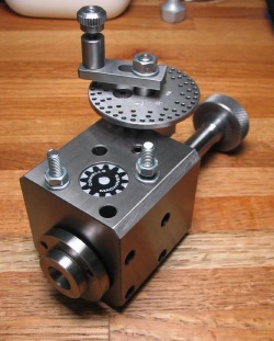
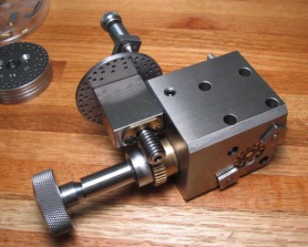
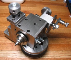
The RGB61 Dividing Head - A fine accessory to the Cowells 90 lathes and for their milling machine as well. As usual, it is constructed almost entirely of steel. The main body is a large steel cube, ground on its surfaces, and can be mounted on two faces. Hole positions allow for mounting to the cross slide or vertical slide T-slots. It uses a 40:1 worm gear arrangement, as usually found on dividing heads. The major difference to take note of with this particular unit, is that it was custom fitted with a 8mm collet holding spindle in place of the threaded nose/Morse taper spindle that is usually provided with the RGB61. It is identical to the headstock spindle on the Cowells 90CW, and has the same tapped flange allowing for the chuck adapter to be fitted for attaching the faceplate or three jaw chuck, etc. The head has an adjustment to correct backlash. A clamping screw to fix the spindle is provided, and this provides a means of increasing the rigidity when needed.
Cowells offers a series of standard division plates (RGB62 A-F), made from ground steel. The plates have the following hole counts:
(A) : 15 - 21 - 37
(B) : 16 - 23 - 39
(C) : 17 - 27 - 41
(D) : 18 - 29 - 43
(E) : 19 - 31 - 47
(F) : 20 - 33 - 49
By means of the worm gear ratio and the choice of division circle, the dividing head spindle can be indexed through a wide range of different counts. As Cowells state on their website, index counts from 1 to 40 and the following up to 120 are possible: 41, 42, 43, 44, 45, 46, 47, 48, 49, 50, 52, 54, 55, 56, 57, 58, 60, 62, 64, 65, 66, 68, 70, 72, 74, 75, 76, 78, 80, 82, 84, 85, 86, 88, 90, 92, 94, 95, 98, 100, 104, 105, 108, 110, 115, 116, and 120, and on to a maximum of 392 divisions. They also offer custom made division plates to fill in any gaps that may be needed.
This setup will be useful for a number of different tasks. The usual advantage is the ability to index to a large number of positions, and index plates for the headstock can be made, etc. My primary reason for use on the Cowells lathe is that the wheel and pinion cutting motor, as I mention on this page above, can not be set to drive the milling spindle parallel to the headstock. Therefore using the milling spindle to drill into headstock mounted work is not possible (without some sort of modification). Using the dividing head, work can be mounted in the head while on the vertical slide and the headstock used to machine the work. This way, items such as lantern pinions, or laying out circular hole patterns can be easily performed, as well as any milling/drilling operations where the work must be positioned and can be held in a chuck, for example, work can be held in the faceplate and coordinated drilling performed using the cross and vertical slides. Also milling squares or hexes, or some other number of flats can be easily setup. Some wheel and pinion cutting, or other milling type operations could also be setup using the dividing head, however, in my case this would only be done if I did not have the required index count on a headstock plate. Overall, it is very versatile attachment to the Cowells machine, and found myself using it more than I initially expected.
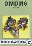
Cowells provided some basic instructions and a copy of a hand drawn chart of available divisions using the 6 index plates. Rather than scanning the document, I reproduced the chart and attached it below as a PDF. The instructions are fairly simple, and any machinist handbook provides the principals of operation. If looking for complete book on dividing, No. 37 of the Workshop Practice Series ("Dividing," by Harold Hall) covers just about every aspect including making your own.
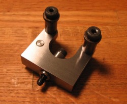
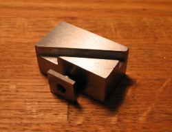
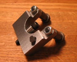
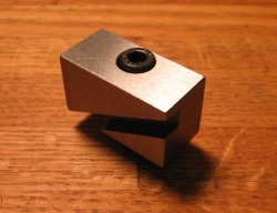
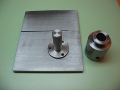
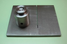
A spacer block was made to mount the dividing head on the cross slide and bring its center height to lathe center. Click here to see the details.
| Cowells Dividing Head - Indexing Chart | |
| File Size: | 155 kb |
| File Type: | |
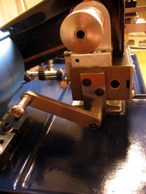
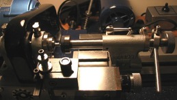
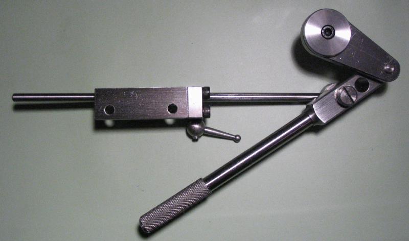
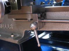
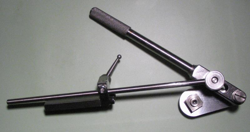
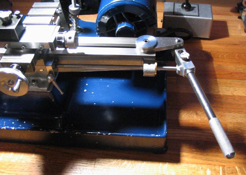
RG73 - Saddle lever feed attachment. I initially ordered my lathe with a lead screw and graduated dial for advancing the cross slide saddle. I found this to be very useful for general turning, especially for longer lengths of material and as the primary means of measuring the movement of the cutting tool. The compound slide is often used, but I find the additional means of advancing the slide with a graduated dial to be indispensable in some situations. However, Cowells offers an alternative means of advancing the cross slide, which is a lever feed. Although it is not graduated, it allows for rapid and sensitive movement of the cross slide. It is especially useful for wheel cutting where the cross slide must be advanced and returned numerous times. This can be done with the lead screw, but can be a bit tedious as the movement is only 1mm per revolution. I acquired the lever feed with wheel cutting duties specifically in mind. The lever or leadscrew options are fairly simple to exchange on the machine, and they both attach to the cross slide saddle by the same means without any permanent modifications.
The lever assembly is anchored to the lathe using the T-slot of the lathe bed, and, therefore, occupies a small amount of real estate at the rear of the machine. A clamp is mounted onto the cross slide saddle with two bolts. The lever actuates a rod which passes through the clamp, and and is tightened the ball handle. The lever will then move the saddle and cross slide. The lever stroke provides up to about 1.75" (45mm) of saddle movement.
