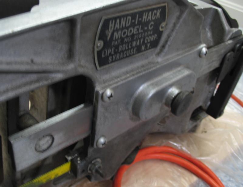
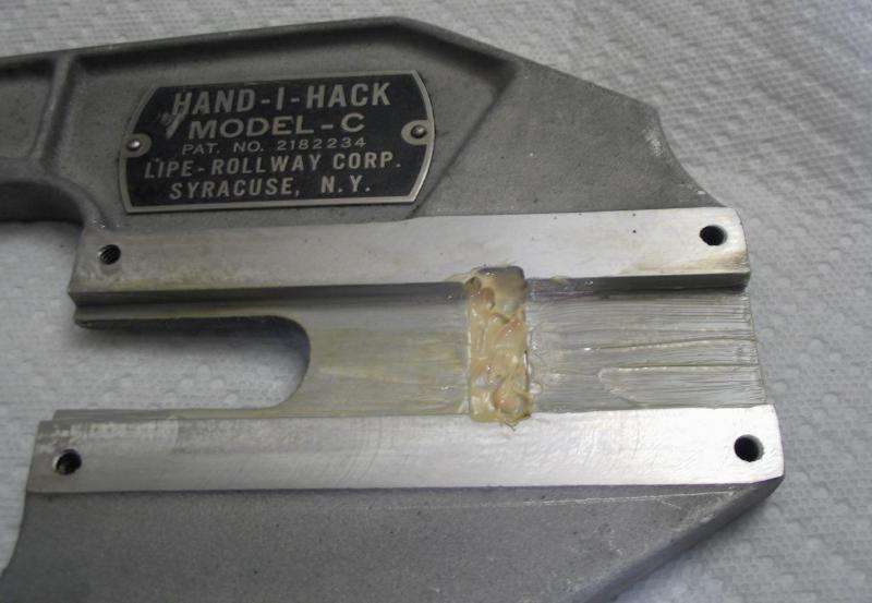
Lipe-Rollway HAND-I-HACK Model C
On many pages of this website, I lament on the need to hacksaw stock by hand. It is a tedious and labor intensive process that results in uneven cuts and a very coarse finish. This causes significant wastes of time, both the time to saw the material and then to file or machine the stock even.
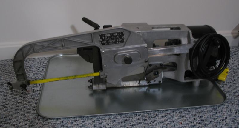
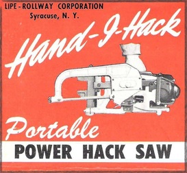
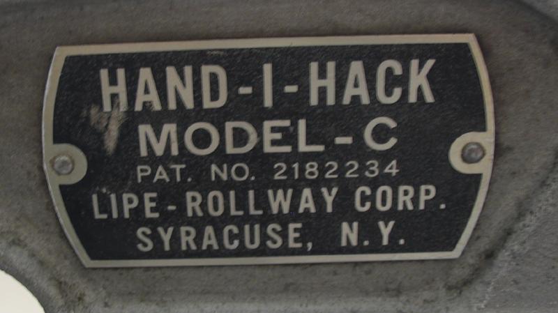
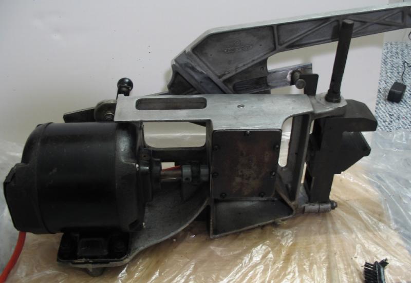
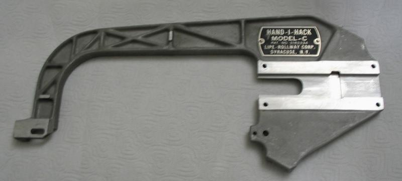
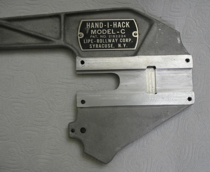
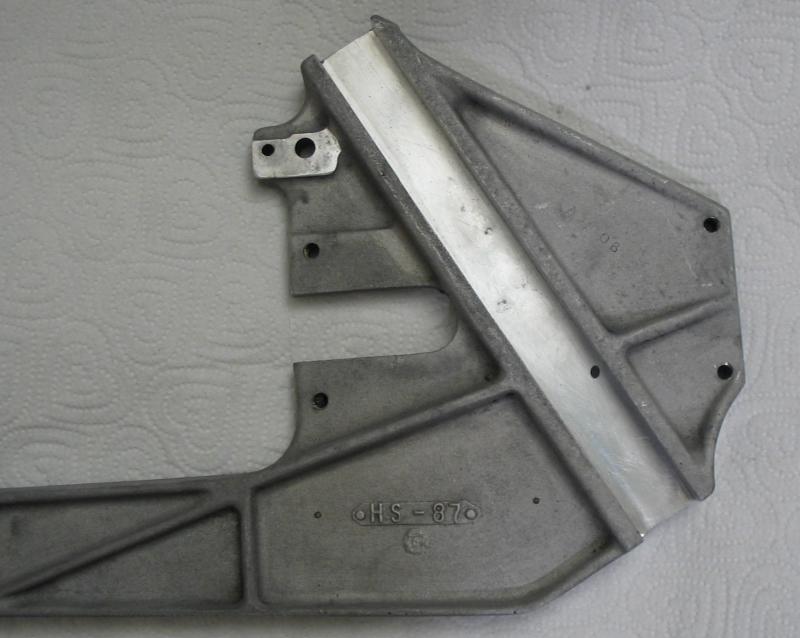
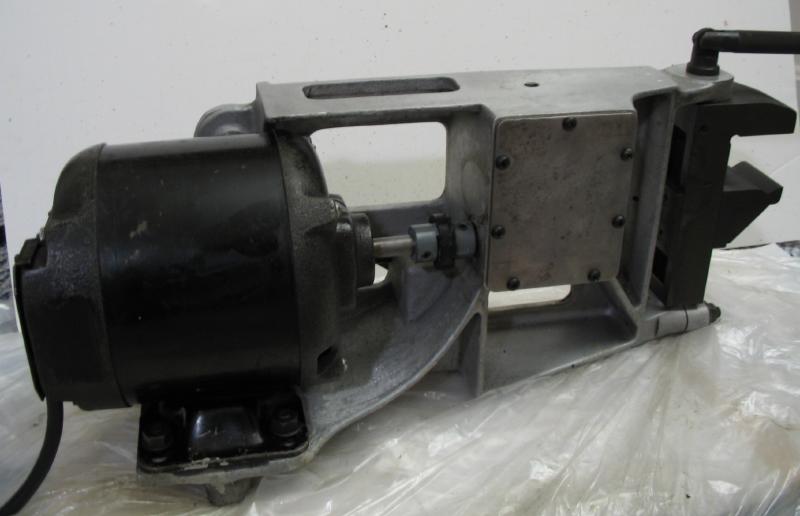
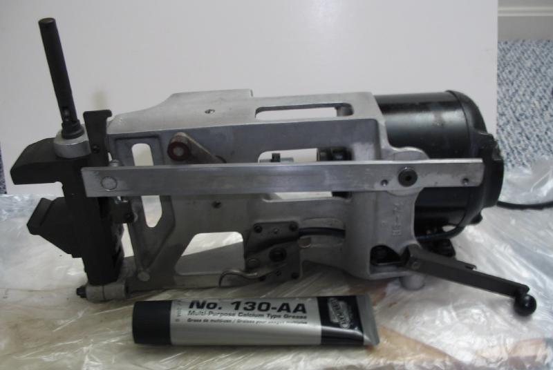
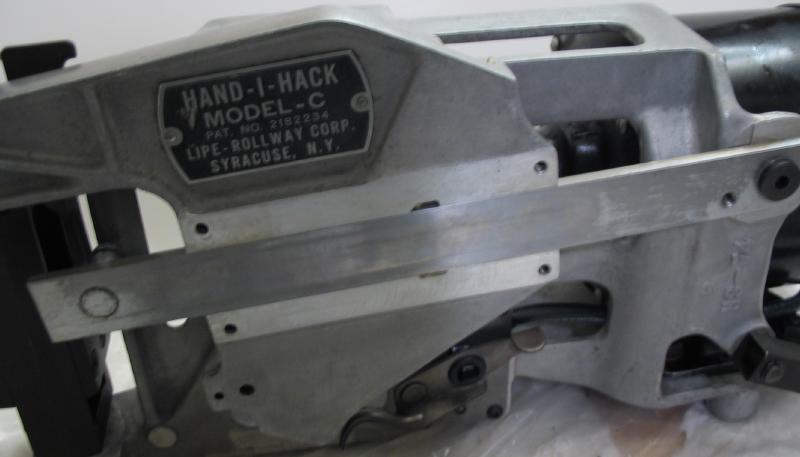
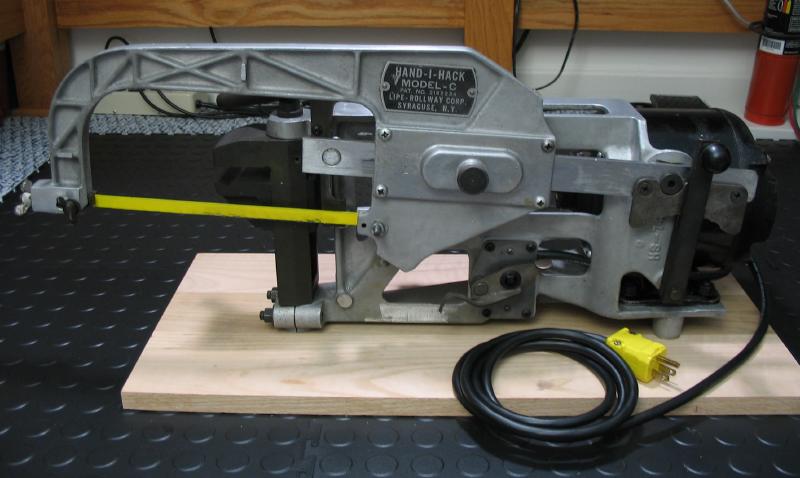
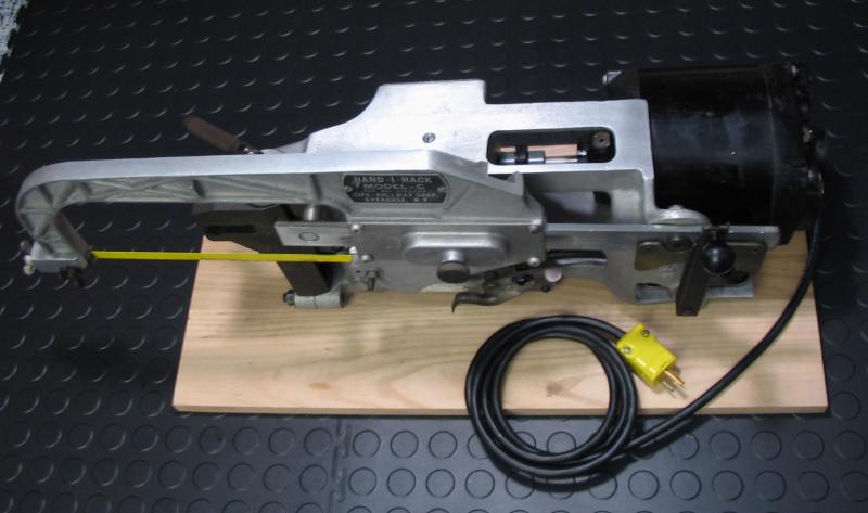
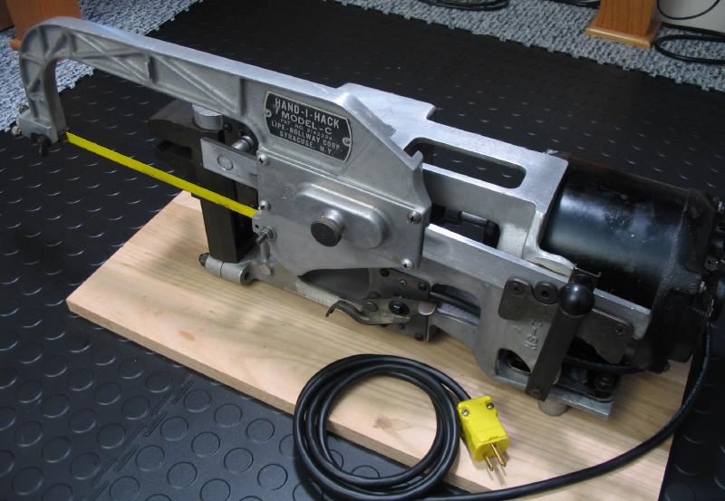
There are various machines available to help preform this task, but a rather clever one is simply a mechanized form of hacksaw. On this page I will describe the Hand-I-Hack power hacksaw that was made by the Lipe-Rollway Corporation. I was not able to find much information on this machine. The patent number is listed on the nameplate, and a copy of the patent is below (dated 1939). I also found a copy of a brochure from 1950 on a Yahoo group dedicated to power saws. The machine in the brochure closely resembles the machine described below. The machine uses standard 10 inch hand hacksaw blades, and overall is constructed very simply. The body is an aluminum casting with machined mountings for all the other components. The casting even includes a built in handle. It weighs about 50 pounds and runs on a 1/4 HP AC motor (1725 RPM). The "semi-steel" vise for holding stock is mounted directly in the main casting and pivots for cutting angles or miters.
There are various machines available to help preform this task, but a rather clever one is simply a mechanized form of hacksaw. On this page I will describe the Hand-I-Hack power hacksaw that was made by the Lipe-Rollway Corporation. I was not able to find much information on this machine. The patent number is listed on the nameplate, and a copy of the patent is below (dated 1939). I also found a copy of a brochure from 1950 on a Yahoo group dedicated to power saws. The machine in the brochure closely resembles the machine described below. The machine uses standard 10 inch hand hacksaw blades, and overall is constructed very simply. The body is an aluminum casting with machined mountings for all the other components. The casting even includes a built in handle. It weighs about 50 pounds and runs on a 1/4 HP AC motor (1725 RPM). The "semi-steel" vise for holding stock is mounted directly in the main casting and pivots for cutting angles or miters.
|
| ||||
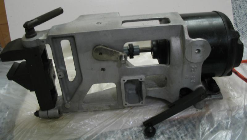
I found this one on Ebay, and to my surprise I got it for a very low price. The 1950 brochure lists $165, which with inflation would be approximately $1500 in 2011 (based on CPI statistics). So I would expect it to be a reliable machine.
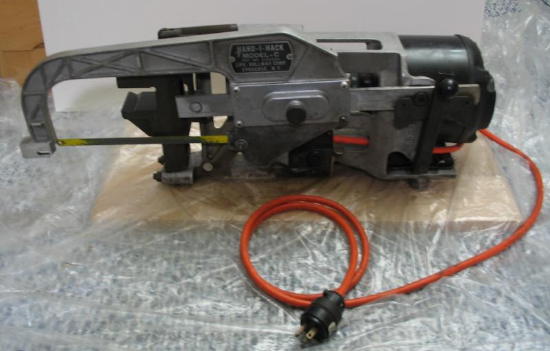
It arrived with a good built up of grease and grime, and did not run when plugged in and switched on. I wiped it down with some degreaser to remove the worst of the grime, but its appearance will improve as you browse down the page.
I am using Simple Green cleaner with a nylon brush, brass wire brush, Scotch-Brite pads, and seemingly countless paper towels. Although the label does not mention a counter-indication for use on aluminum, an internet search results in numerous cautions for using Simple Green on untreated aluminum surfaces. The company addresses the concern on their website, and having already used it significantly on the Hand-I-Hack, I concluded that if the residue is cleaned up immediately, there is does not appear to be any evidence of damage.

DIAGRAM from Brochure
|
|
The vise has a vee for holding round stock and angular graduations.
(0, 15, 22.5, 30 and 45 degrees)
|
|

|
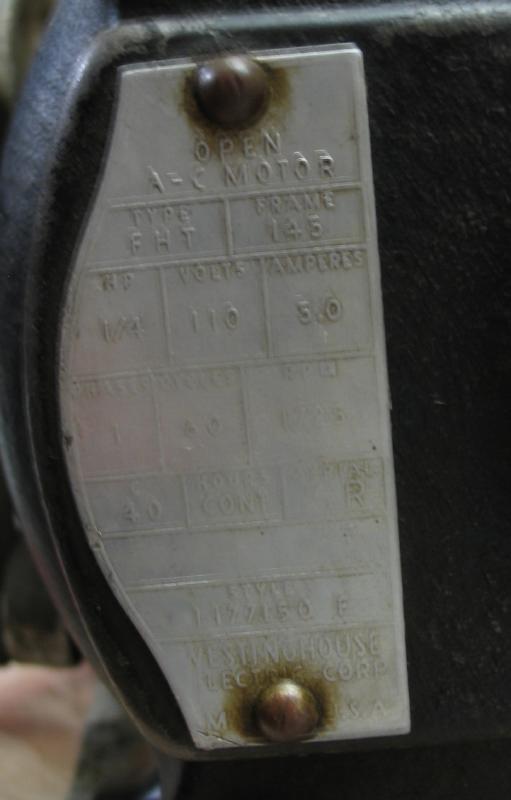
Westinghouse 1177150 F
1/4 HP 110V 3A 60Hz 1725RPM Cont.
|
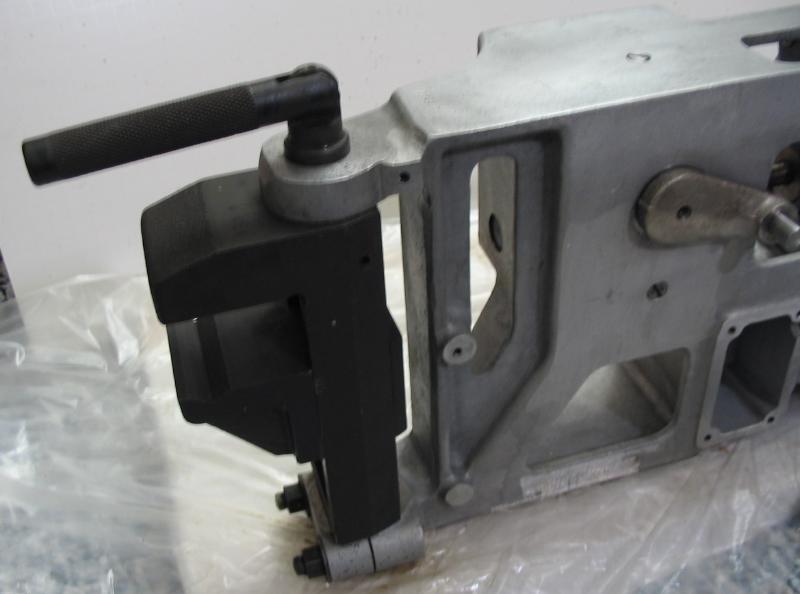
Built in handle
|
|
|
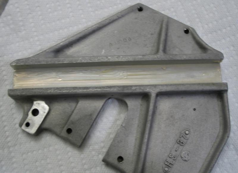
The machine has various numbers located on different parts.
Some are stamped and others are part of the casting.
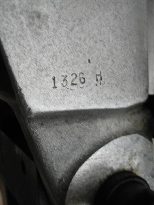
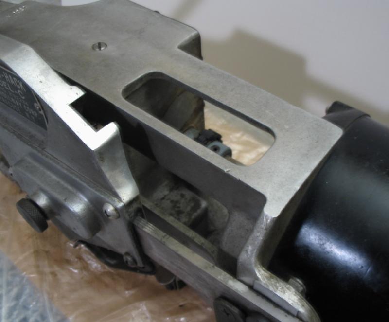
Stamped on top surface
|
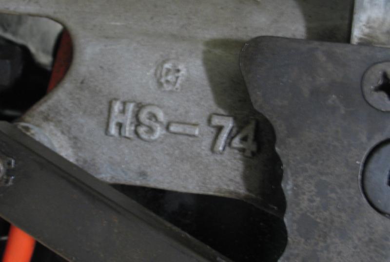
Main casting
|
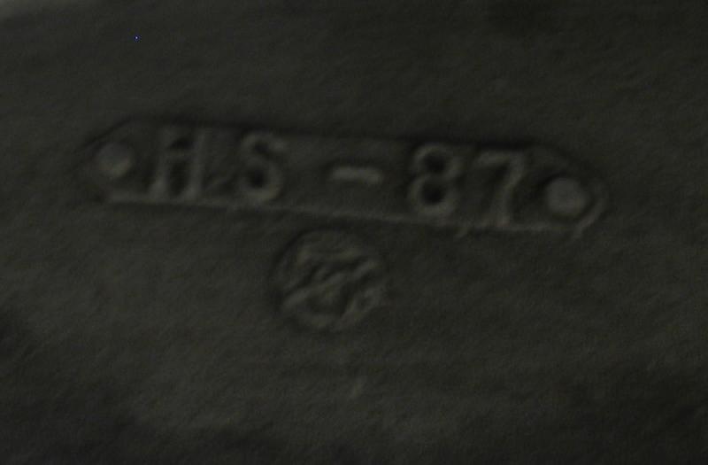
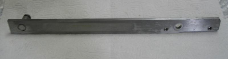
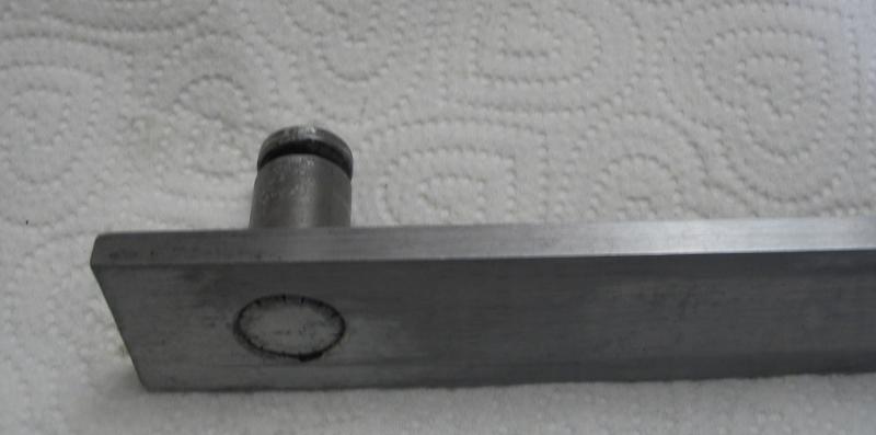
Saw arm
|
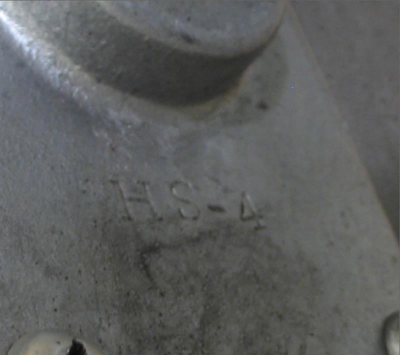
Tensioner casting
|
Saw blade clamp (distal end)
|
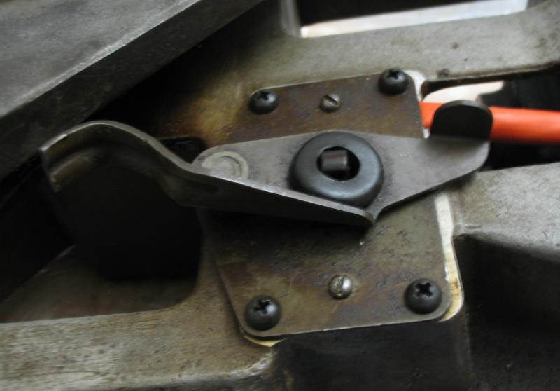
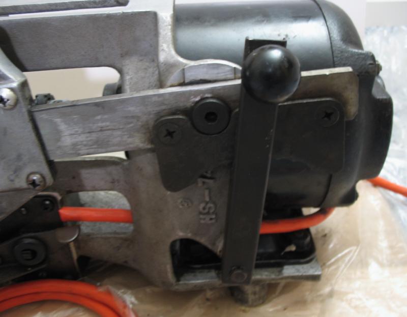
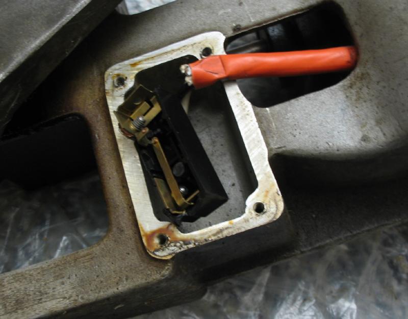
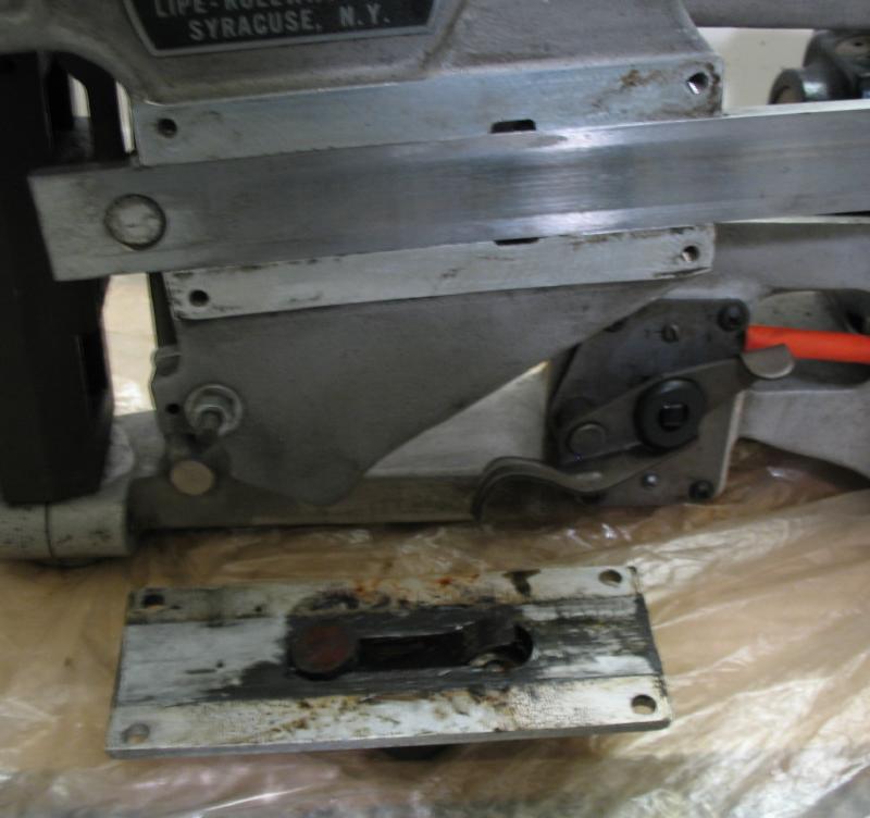
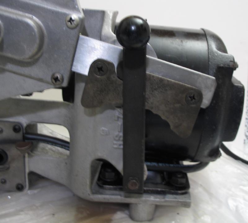
Switch with automatic shut-off lever
|
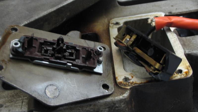
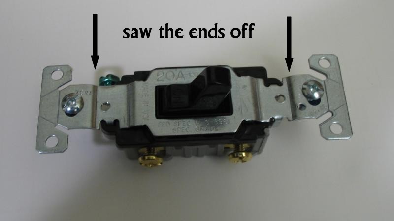
The switch felt loose, so I opened the switch case to discover the switch had been destroyed during the shipping process, likely due to a hard hit to the auto shut-off lever. I do not know what sort of equipment the delivery companies use to handle packages, but I suspect it to be some form of catapult. Fortunately the switch is a simple household light switch (at least those commonly found in US homes). A replacement was found at the local home supply store. The ends of the mounting bracket needed to be sawed off so that it will fit in the case, but the screw positions are kept. The wiring was reattached, and the front plate is screwed to the switch housing. I replaced the works to the saw frame, and success! It will now turn on, but with nothing mounted to saw or even a blade in place, it quickly shuts itself off by striking the lever on the draw stroke.
|
|
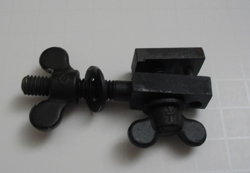
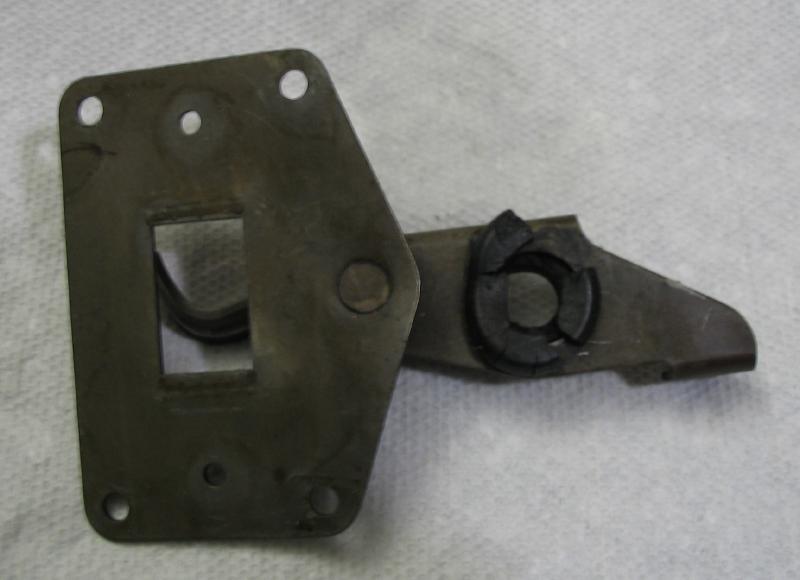
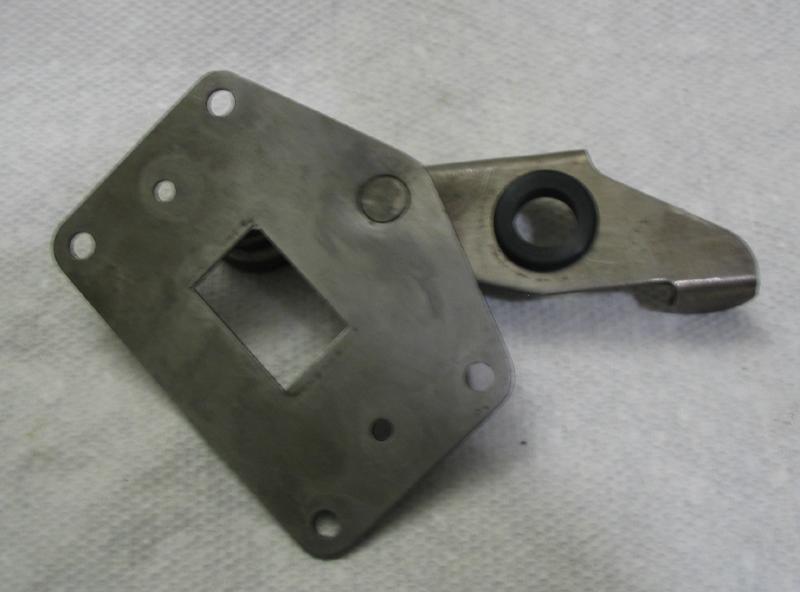
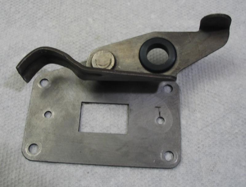
The automatic shut-off lever has a rubber grommet to engage the switch. Obviously, the original has done as much as it can. It was replaced with a new 1/2" grommet. The cover plate could be given another scrubbing while removed.
|
|
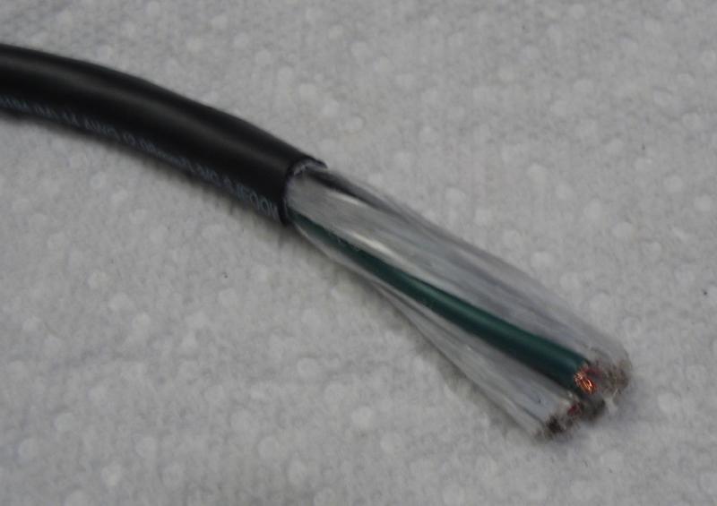
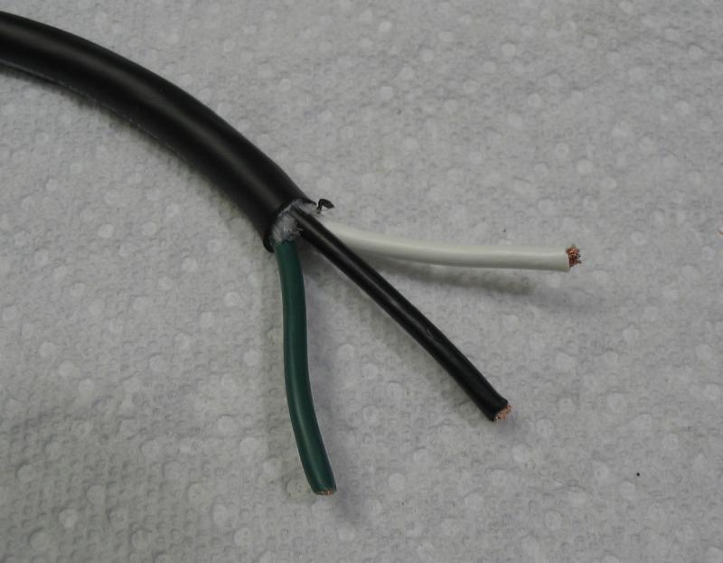
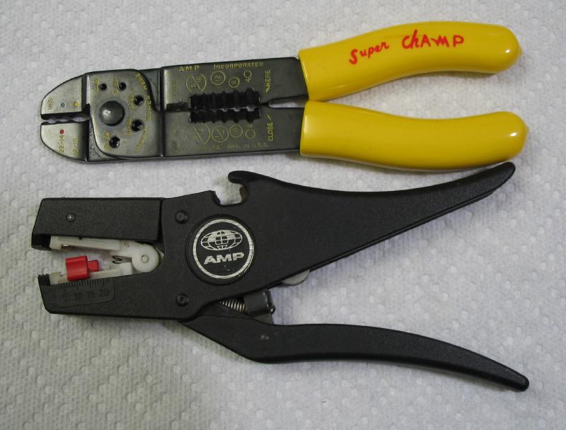
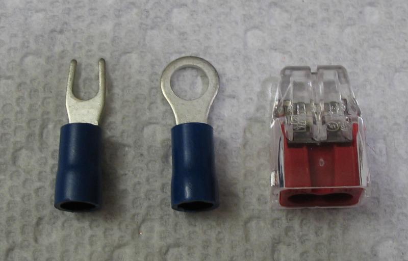
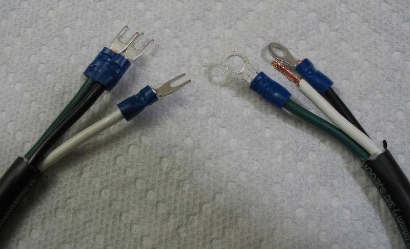
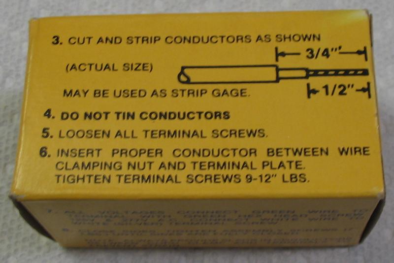
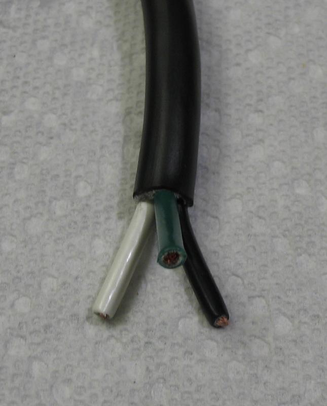
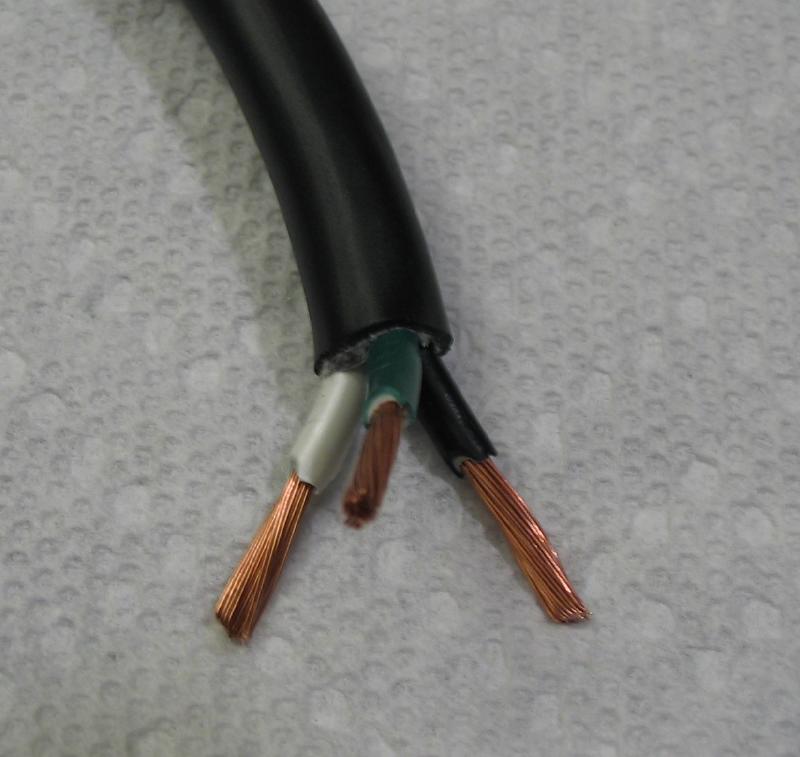
Although not necessary, a replacement switch wire was made from 14 gauge 3-conductor cord (Southwire Quantum). The outer insulation is removed, and the internal insulation trimmed away. The individual wires are stripped about 6mm in length (as per the specifications on the AMP terminals). An automatic wire stripper makes easy work of it. On the switch end all three lines get a U-shaped connector. The connectors are crimped using the appropriate crimping tool. The motor end of this cord gets ring connectors on the black and ground lines. The white wire will connect directly to the black wire from the outlet cord, therefore, it is stripped 1/2" (as per the specification for the coupler).
|
| ||||||
|
|
|

|
|
|
|
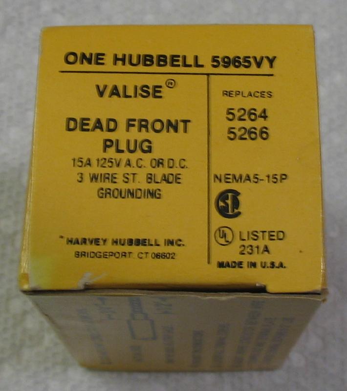
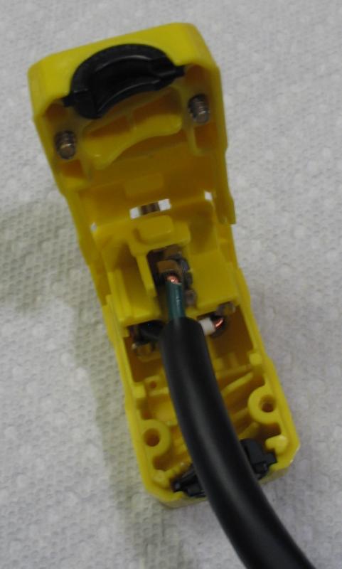
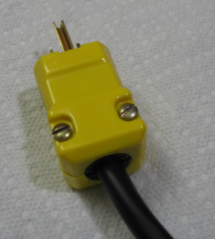
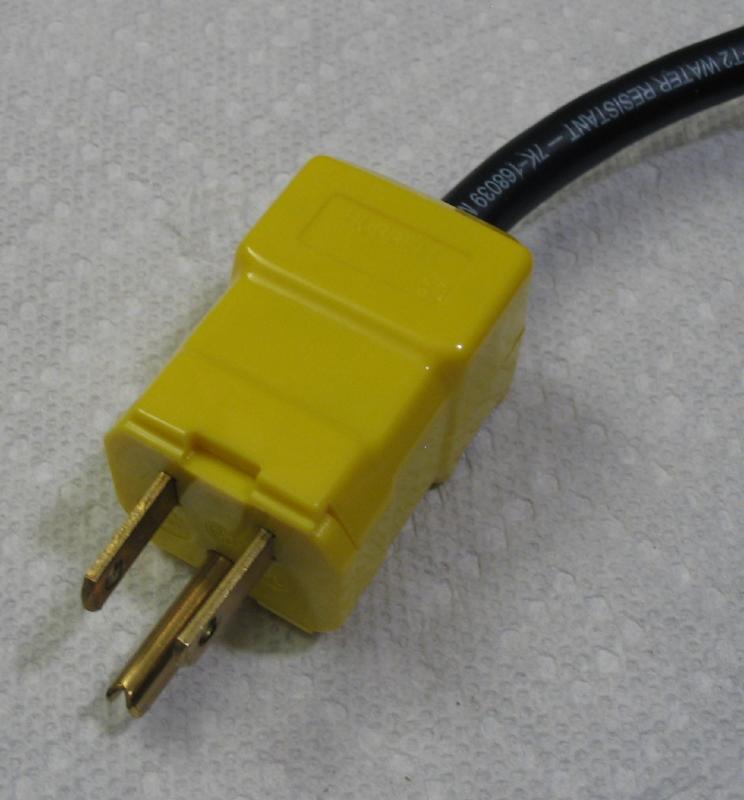
A new 6 foot power cord was made from the same 14-gauge 3-wire cord. For the plug, there are number of brands available, and I decided to use a Hubbell Valise 5965VY. Why? The Cowells lathe and wheel and pinion cutter came equipped with the same, and the plugs are made in the US, so I thought why not.
|
|
|
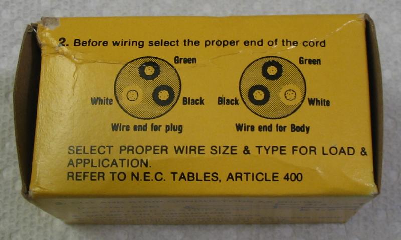
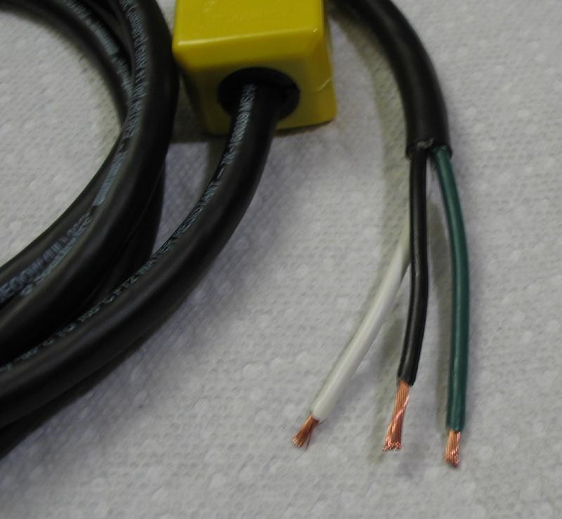
The correct end is chosen, a 3/4" length is exposed and stripped for 1/2".
|
|
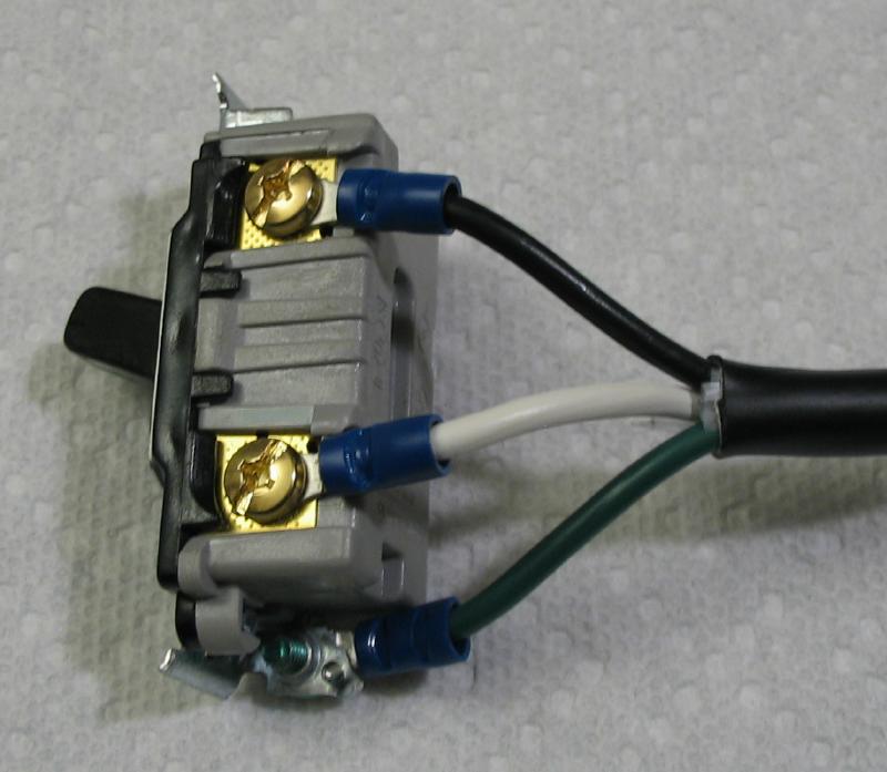
The wires are inserted into their appropriate terminals, screws tightened, and the case closed and the screws secured which clamps onto the cord very tightly.

|
|
|
|
The motor end was given ring connectors on the ground and white wire.
|

|
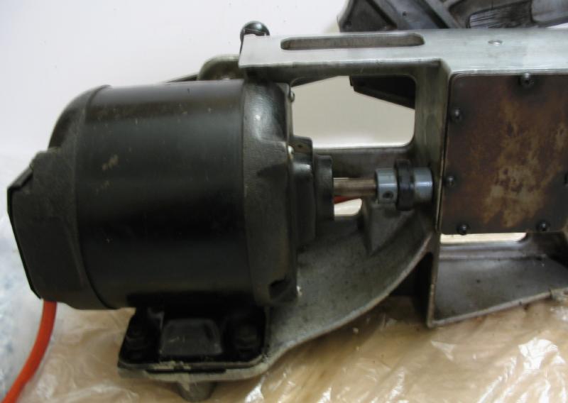
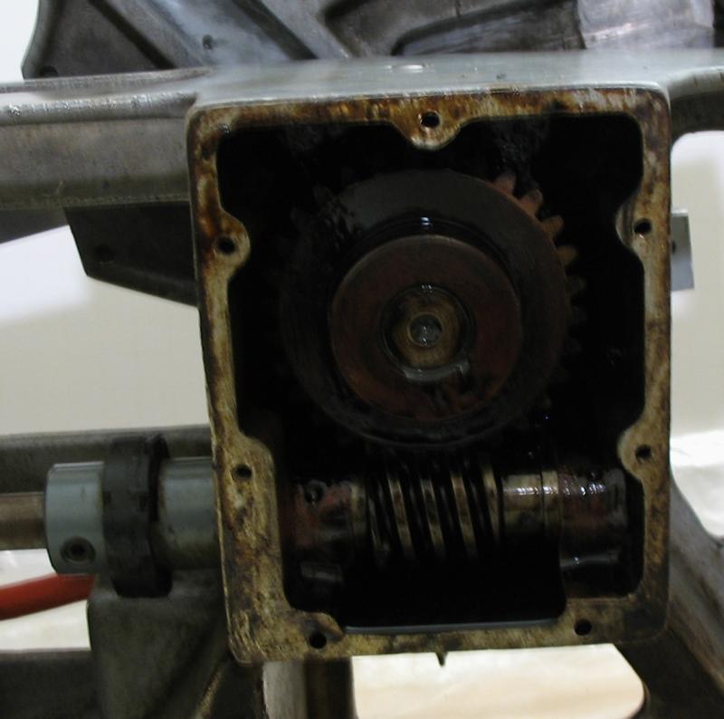
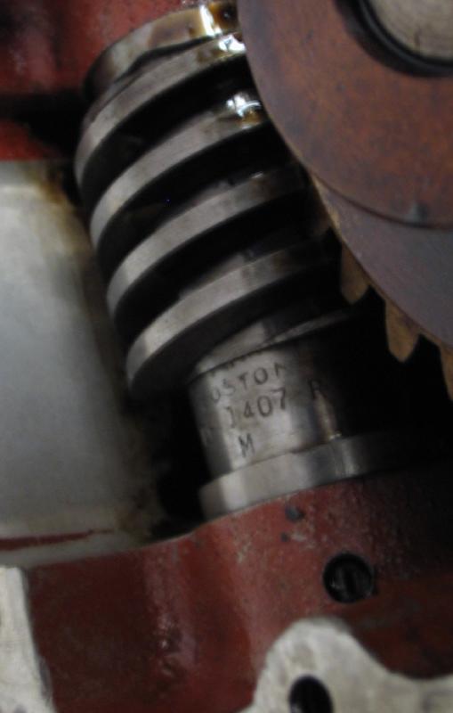
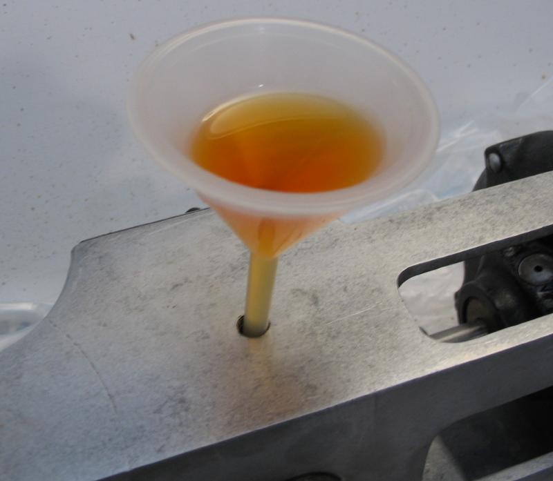
Investigating in the rear of the machine: Feeling confident after replacing the switch, I decided to open the gear box without forethought, and all I can say is that it was a good thing I had it sitting on plastic. The blackened gear oil that spilled forth appeared to be perhaps last changed during the Eisenhower administration. The drive is direct from the 1725 RPM motor to a steel worm screw (Boston Gear DH-1407-R). This engages a bronze gear (Boston Gear DB-1401) which is keywayed to the shaft of the "drop-forged" sawing arm.
| Boston Gear - catalog pages |
|
|
|
Letting it drain out
|

Still dripping, but wiped out. The works is stained red.
|
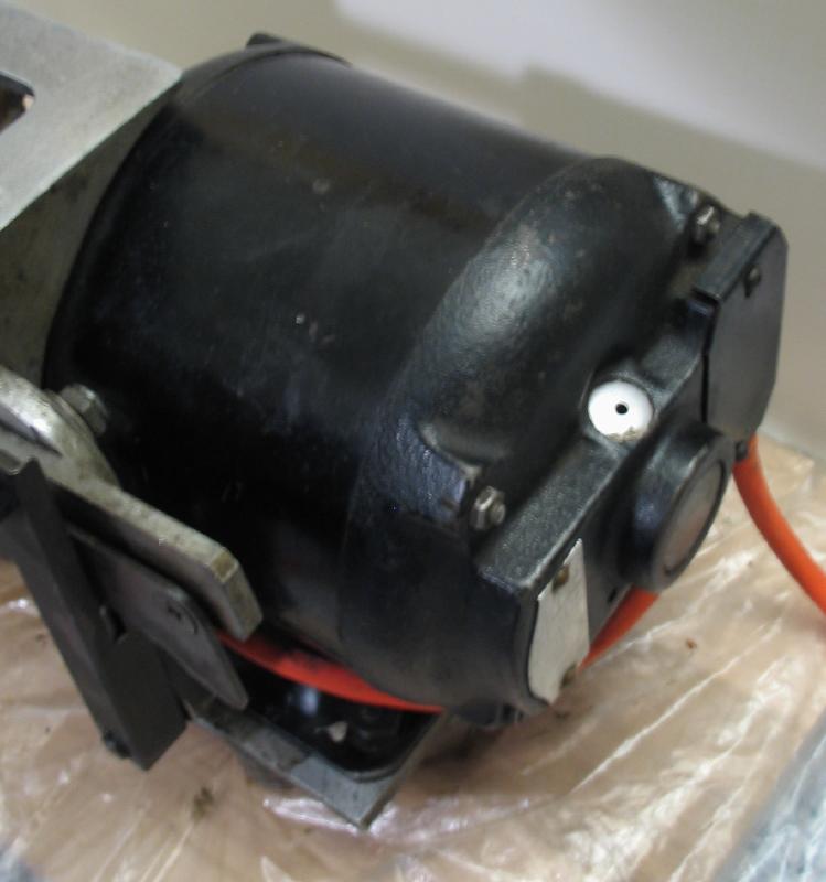
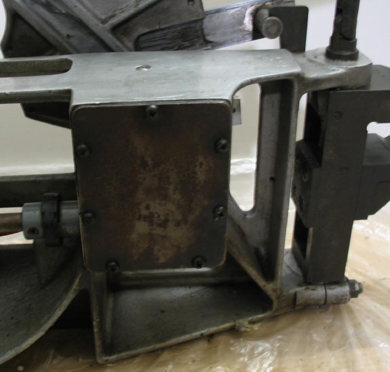
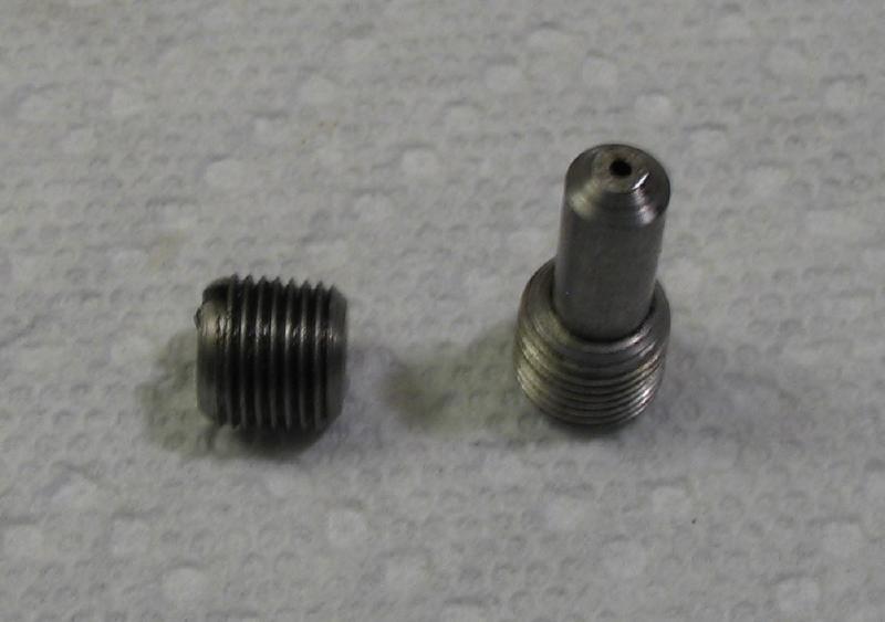
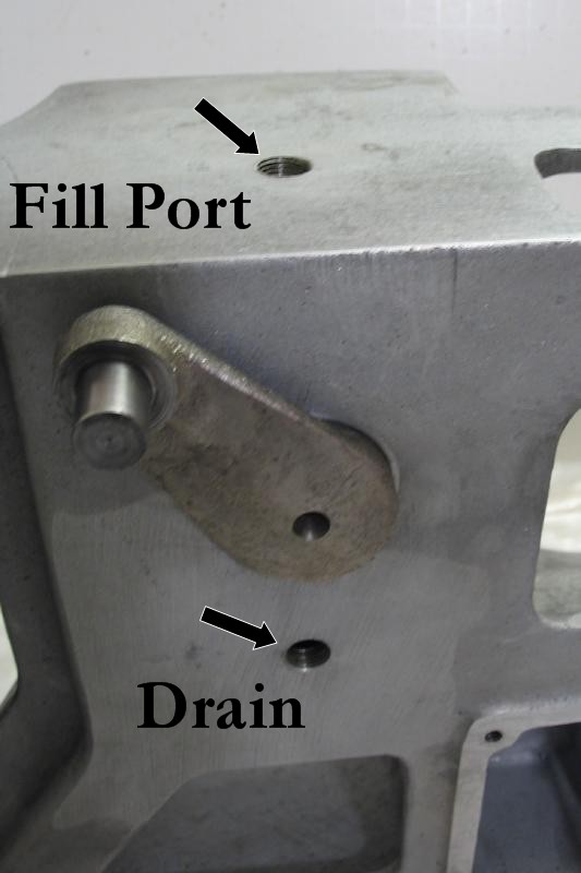
The gear box has two tapped holes. The top hole is for filling the enclosure with oil and the lower hole is for sighting the oil level (oil is filled up to this hole). The top hole plug has a hole bored through with an internal ball bearing, likely for air exchange.
|
|
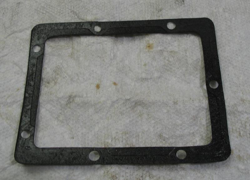
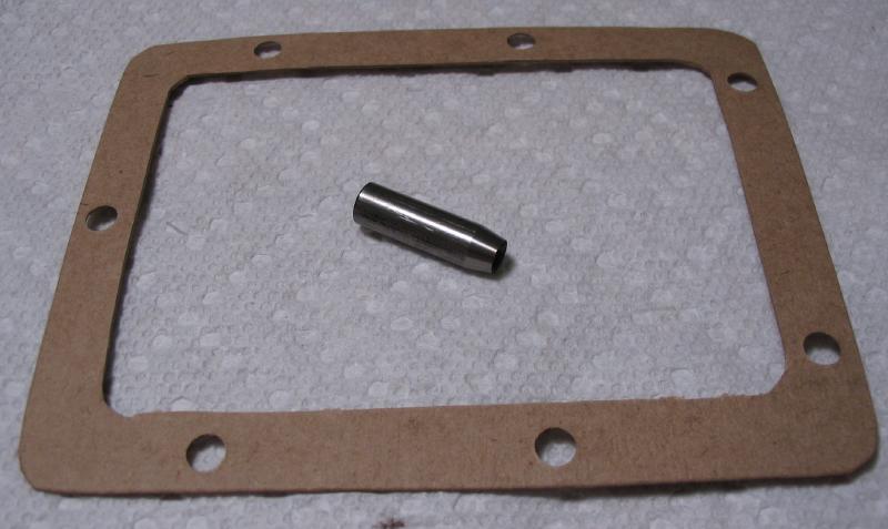
The gasket is cracked, and looks well used.
|
|
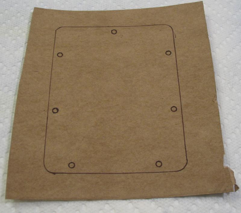
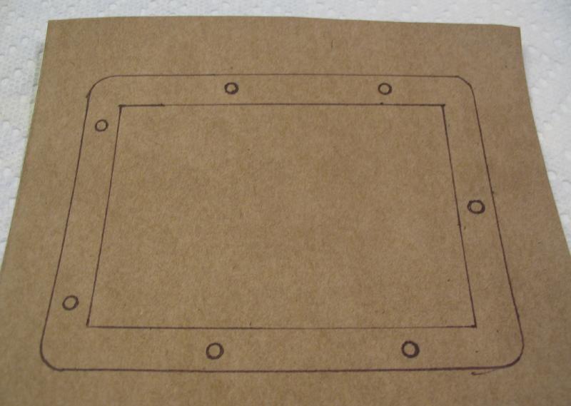
I doubt there exists an off-the-shelf replacement, so I decided to try to make one. I ordered some 1/32" vegetable fiber sheet gasket. The gear box cover plate was used a template to lay out the perimeter and screw positions. The inside dimensions were drawn with a width of 10mm.
|
|
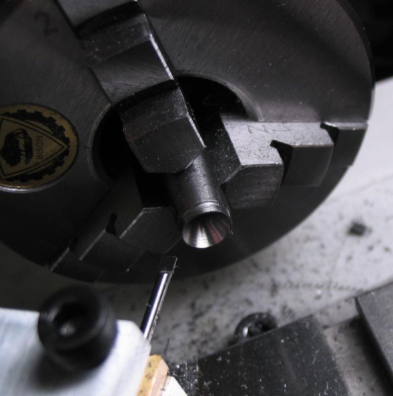
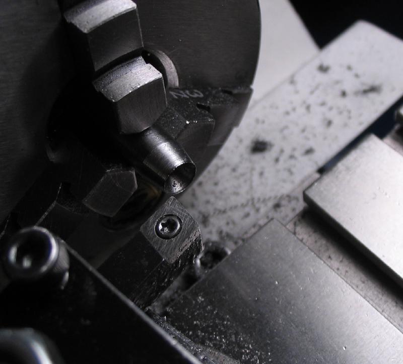
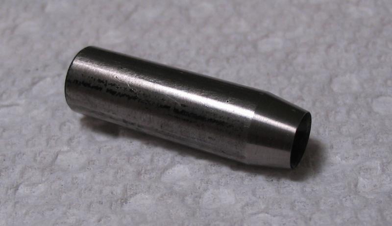
A hole punch was needed to form the screw holes. One was turned up on the lathe from a piece of scrap 8mm O-1 drill rod. It was drilled and counterbored 30 degrees. It was then taper turned 10 degrees to form a cutting edge about 5.5mm in diameter.
|
|
The punch was hardened in oil and tempered to a light straw. The holes were punched on top of an old catalog and using a ball pein hammer.
|
|
|
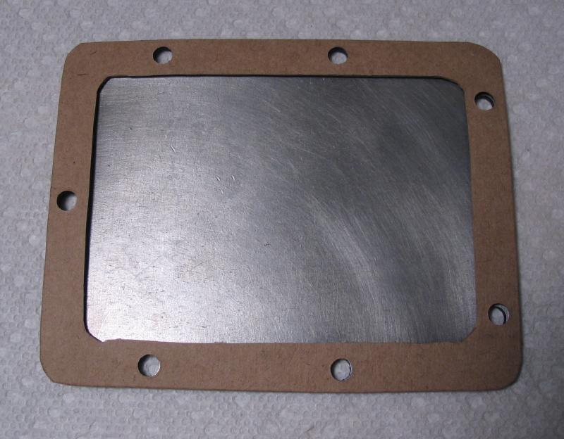
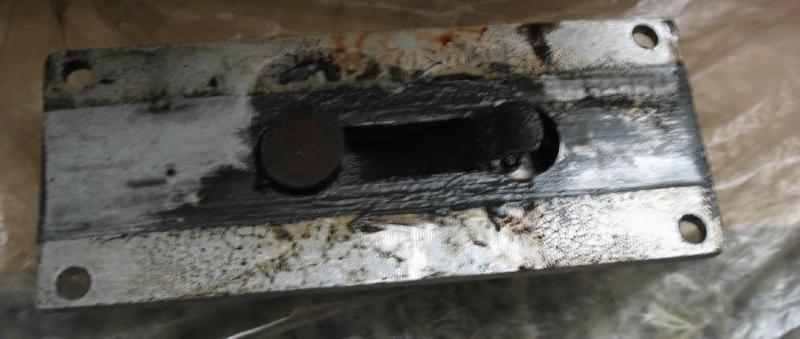
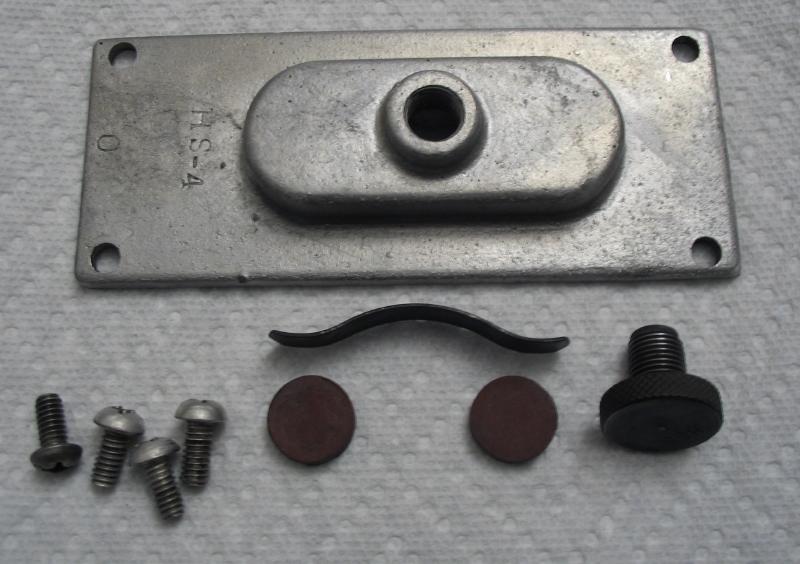
The coverplate with tensioning mechanism was removed.
A build up of blackened grease was found.
|
|
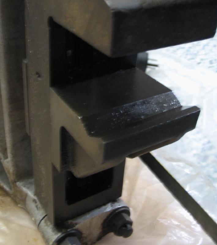
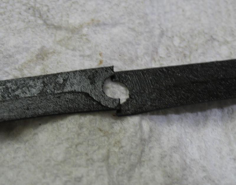
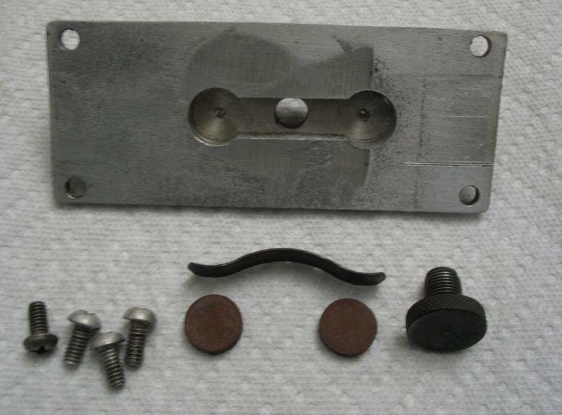
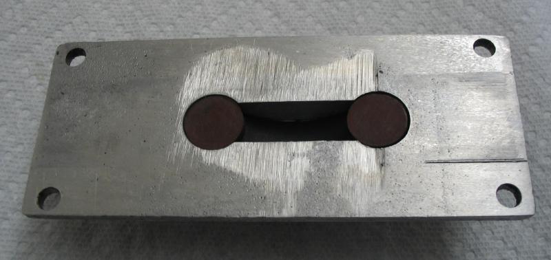
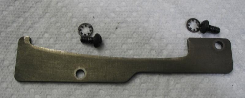
There is an screw with knurled portion that presses into the U-shaped spring and therefore presses two pads against the main guide arm.
|
|
|
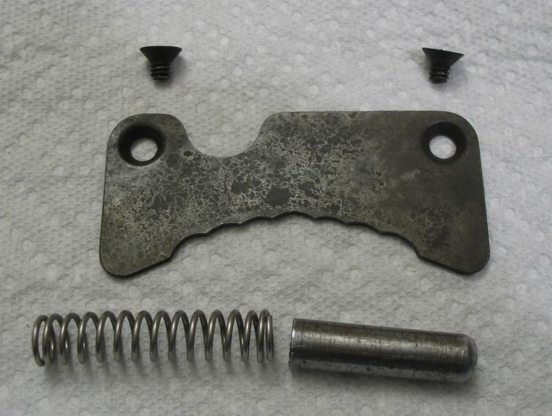
The height adjustment-tensioner was taken apart, to get into some of the tight spots for cleaning. The locking lever has a spring and steel pin that engages the steel plate.
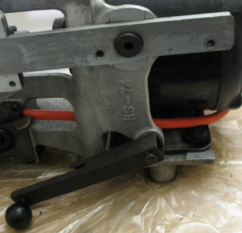
|
|
The pivot bolt is removed to free up the main slide. To remove the saw frame, the forward guide bar was unscrewed as well. Photos are after cleanup.
|

|
|

|
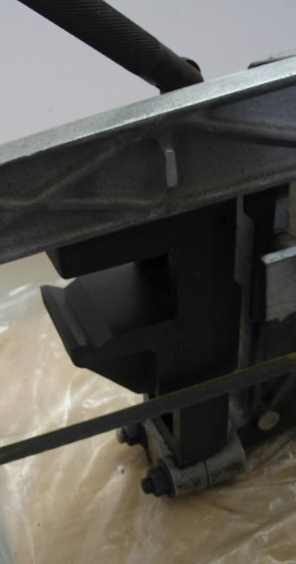
The saw frame can now be removed and finally get a thorough cleaning.
|
|
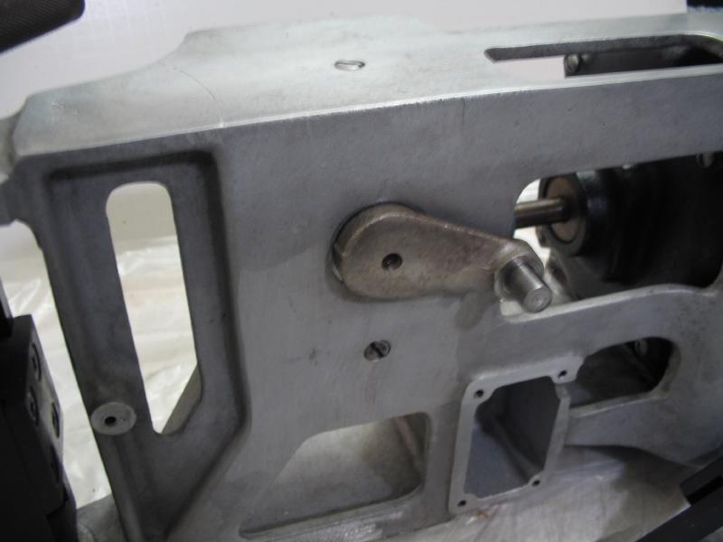
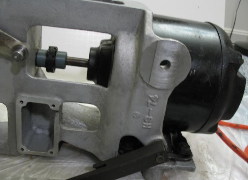
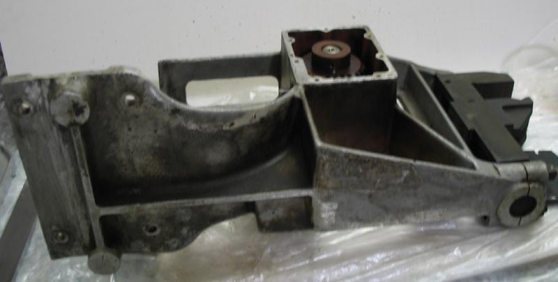
With the saw frame removed, the main casting can be cleaned up a bit more.
The drive arm can be seen, the bearing that engages the slot in the saw frame is removed and shown separately. Appears to be a fiber reinforced, phenolic resin or some other polymeric material.
|
|

|
|
|
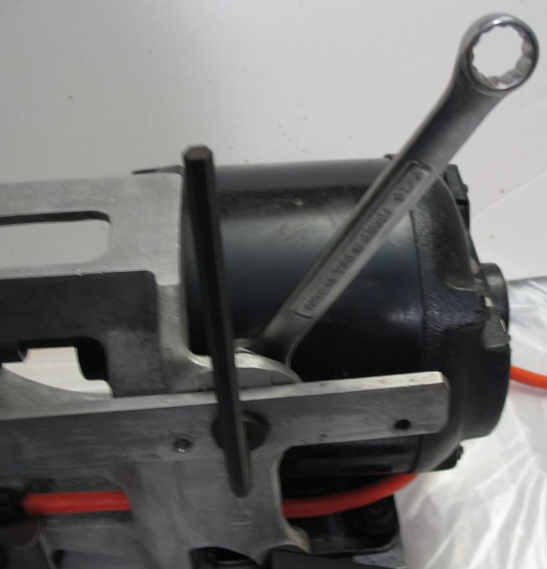
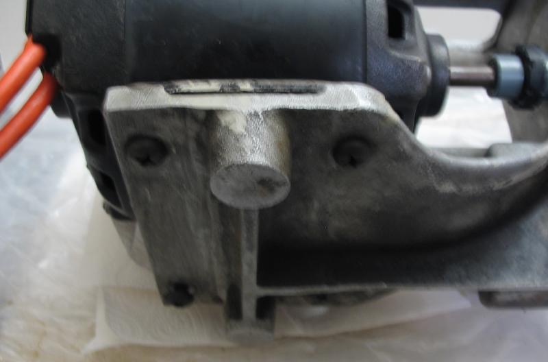
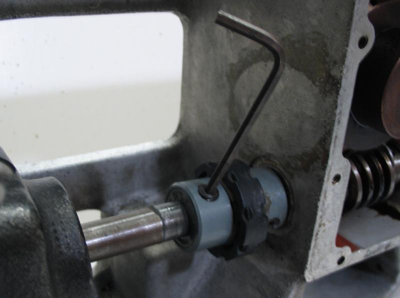
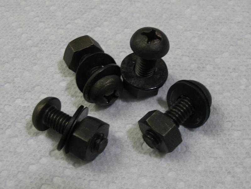
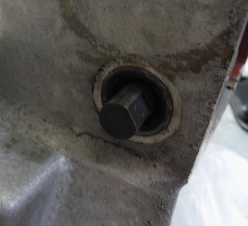
The motor mounting bolts and the set screw on the drive coupling were slackened.
With the machine up-righted, the bolts were removed and the motor could then be removed.
|
|
|
Washed in Simple Green
|
The bottom of machine had a good build up of grime, but it was easily cleaned up.
|

|
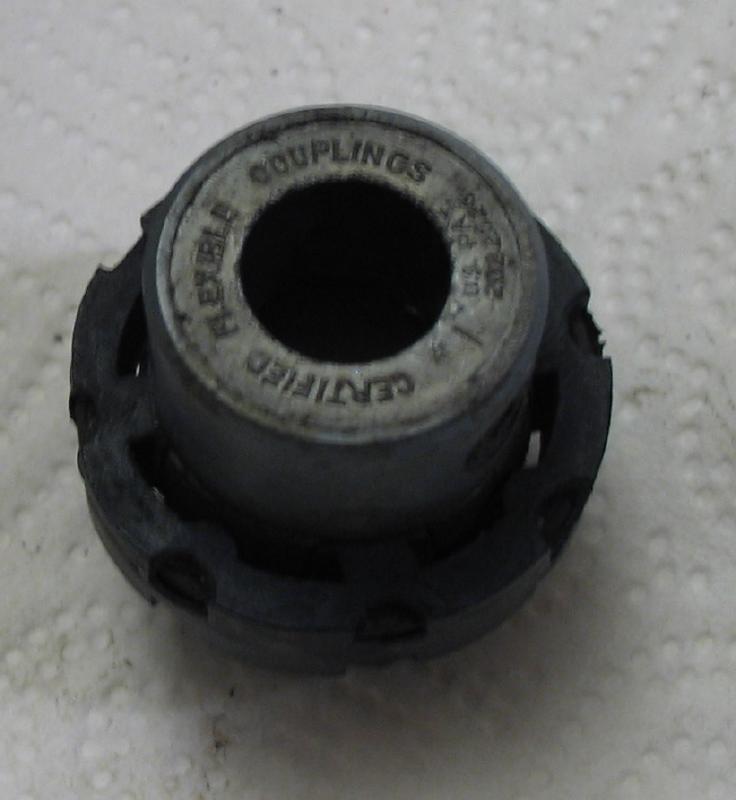
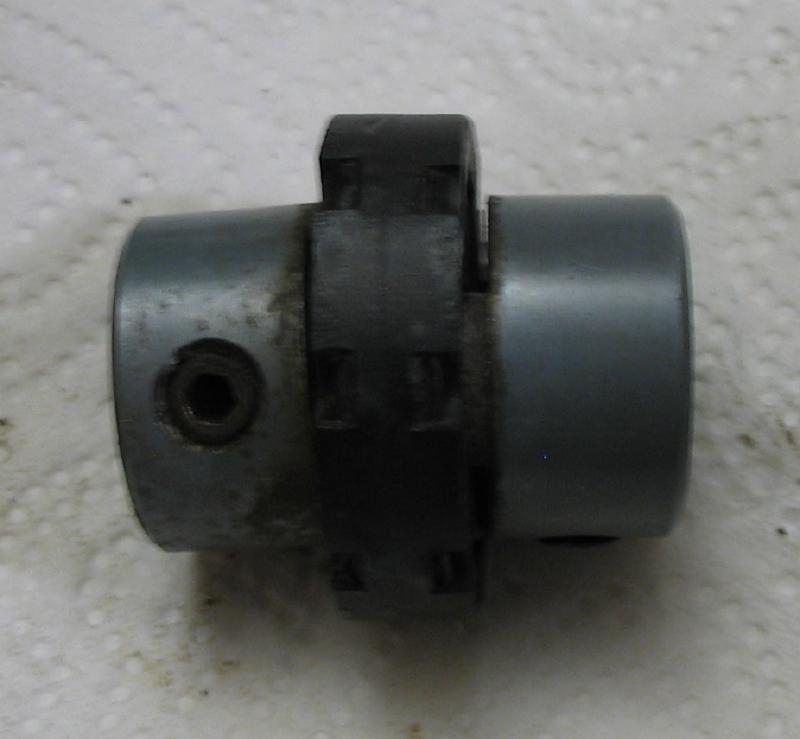
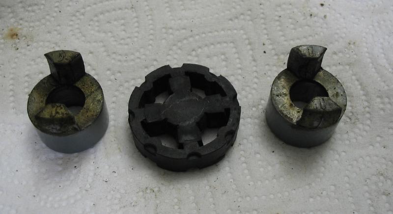
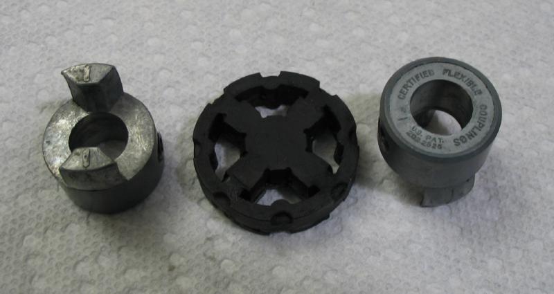
The "Certified Flexible Coupling" is for 1/2" shafts.
|
|
|
|
|
Reassembly...
With everything in pieces, and reasonably cleaned, the process of getting it back together begins. The motor was replaced on the casting and bolts installed. The old wiring was removed and the new wiring (made above) was installed.
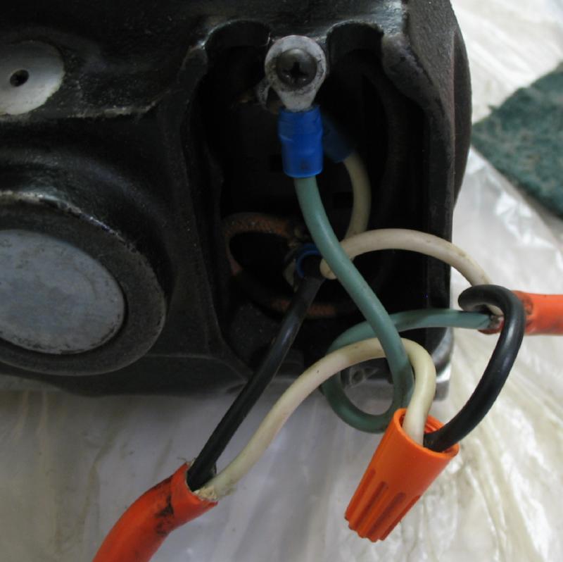
Previous Wiring
|
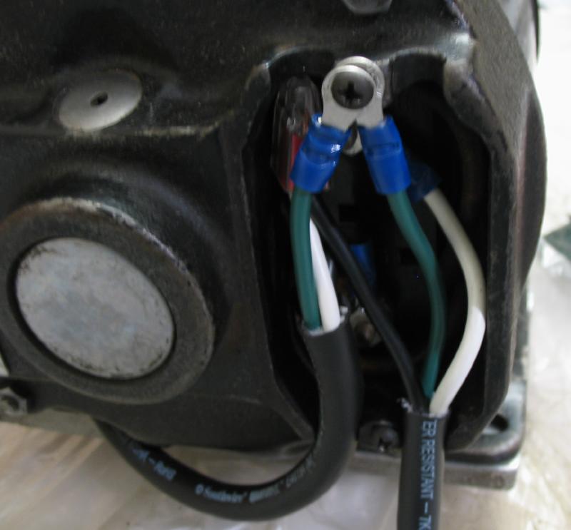
New wiring installed
|
The cover plate and home-made gasket were attached. It was filled with oil and observed for leaks. I decided to use Mobil SHC 630. The product specifications describe use with worm gear applications and for long term ("Fill-for-life") gear box use.
| Mobil SHC 600 Series |
The machine was run periodically for several minutes over a week. Some initial leaks were detected around the drive arm, but then stopped. The gasket also leaked a few drops a day. The gasket appeared to saturate with oil over time. The screws could be then be tightened another 1/4 to 1/2 turn. Little to no leaks afterward.
The pivot bolt and all sliding components were greased with Lubriplate 130-AA . The saw arm has a milled area that appears to be a grease reservoir. Other surfaces were given a light smear.
|
| ||||
|
|
|
|
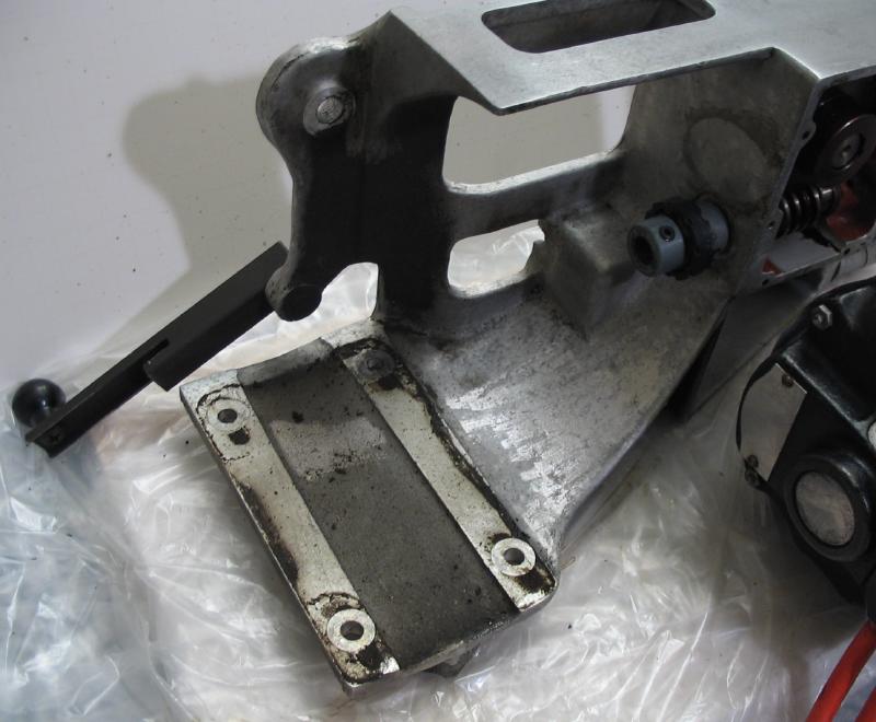
The tensioner cover plate was attached to the saw arm.
The height adjustment plate was installed and the locking arm moved into position.
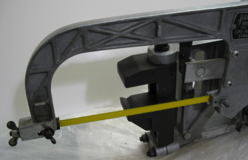
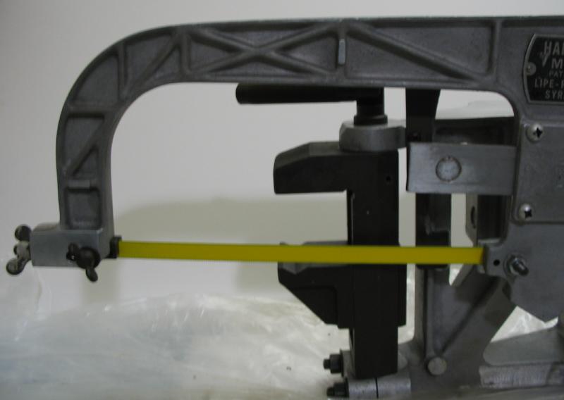
The machine uses standard 10 inch hacksaw blades.
Shown are Starrett blades with 18, 24, and 32 teeth per inch.
| Starrett Hand Saw Catalog |

A new 18 TPI saw blade was installed and tightened. The saw cuts on the draw stroke, which is the opposite of how a hacksaw is normally used.
|
|
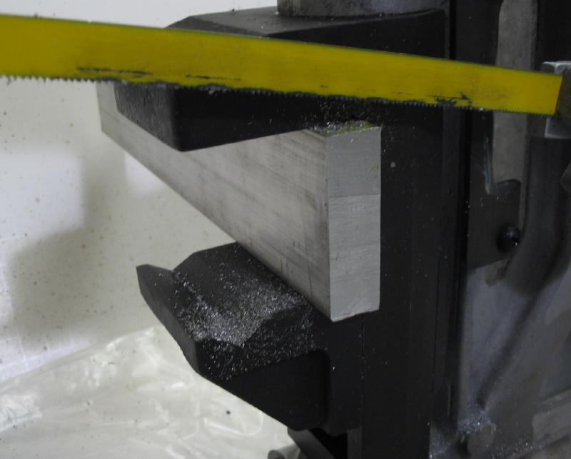
With it still sitting on the plastic sheet from cleaning, I decided to give it a trial run. I was curious to see how it works and how much of a mess it makes. For its first job, it will cut off a 2.5" section of 2" x 5/8" aluminum (6061) bar.
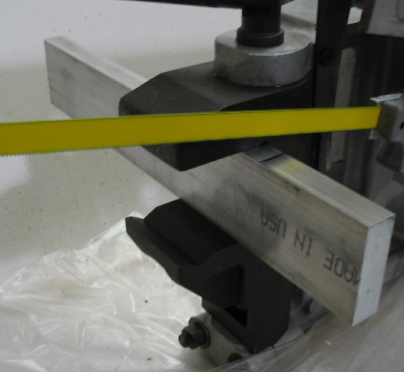
The machine worked beautifully. The finish is excellent, there is a section where the finish was coarse, and the height-adjustment lever was moved to the next stop and the sawing improved.

|
|
A few photos after tidying up.
|
|
During use it was ultimately placed on a sheet-metal oil pan to collect the sawing debris and the occasion oil drips from the gear box.