Case Band and Bezels
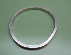
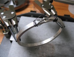
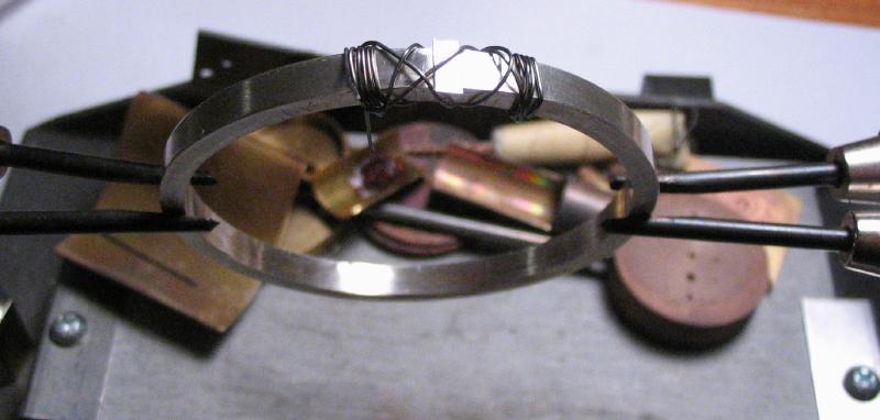
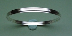
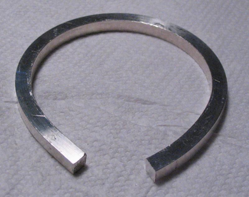
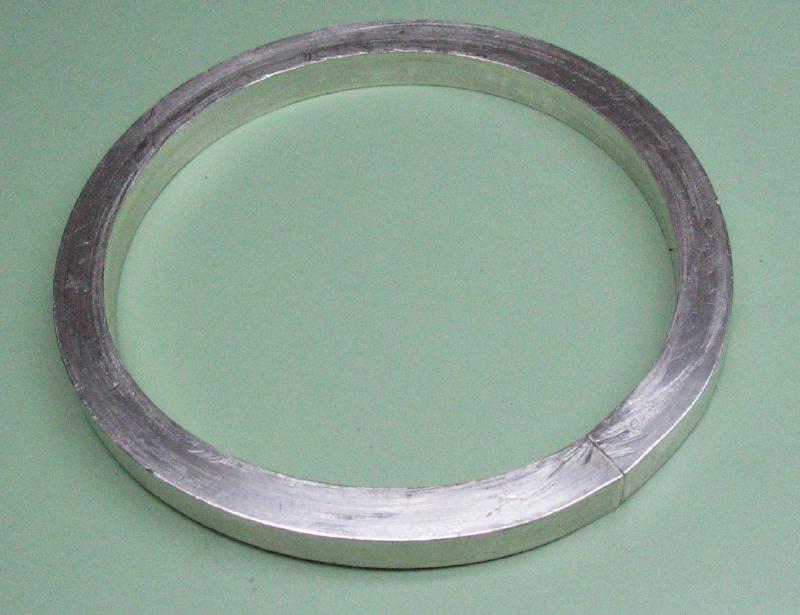
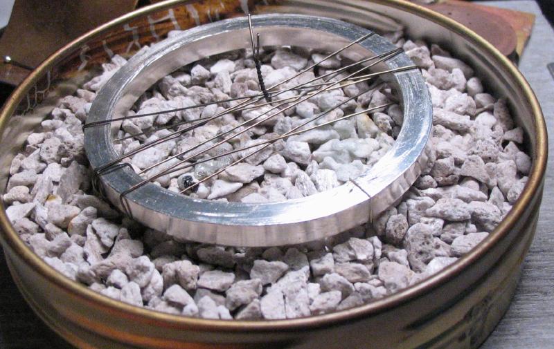
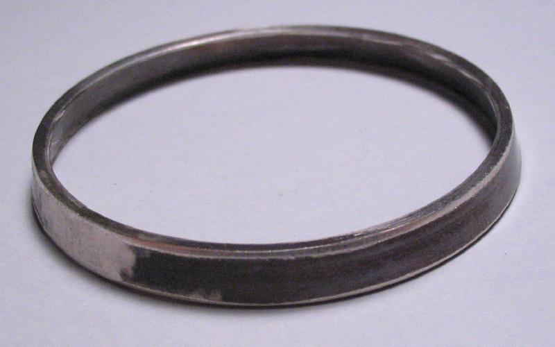
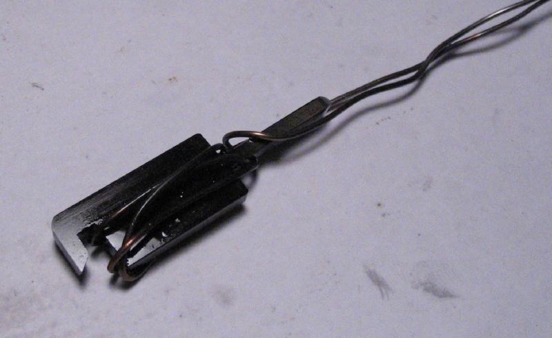
The watch case was started with the central band. A length of rectangular Sterling silver wire (3/16" by 1/8") was bent into a roughly circular shape and the ends mated together for soldering. I started this a while back without much thought going into it and prior to making the bezel forming tool. The length of material I used was a bit too long, and this may have simply been due to my being a little too generous when sawing it off. Daniels recommends determining the required length with the formula L=3.3xD, which may be a good approximation. However, I determined the length by adding the desired internal diameter to the thickness of the wire and then multiplying by pi (i.e., the circumference measuring through the center of the wire). The latter comes out about 1mm longer. I also used too much force with the pliers while shaping the wire into a ring (or more likely when foolishly attempting to reshape it by hand afterwards), which left a number of nicks in the surface. However, these should be removed later when machining the ring to its final dimensions. I had soldered the ring closed by securing it with iron wire and placing a chip of "hard" silver solder over the joint. It was then brought up to temperature with a propane/oxygen torch to melt the solder.
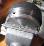
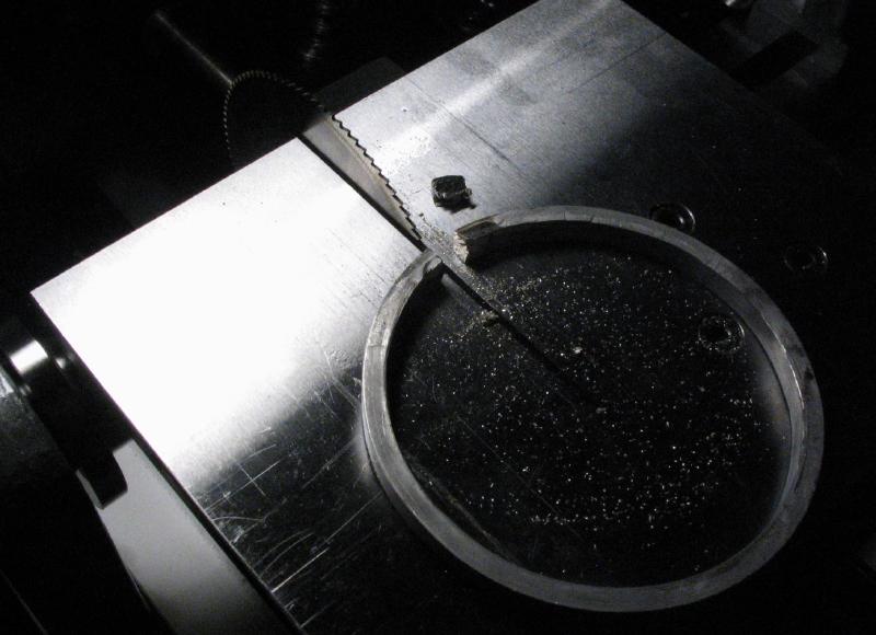
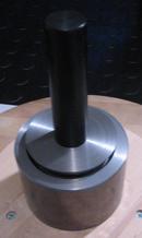
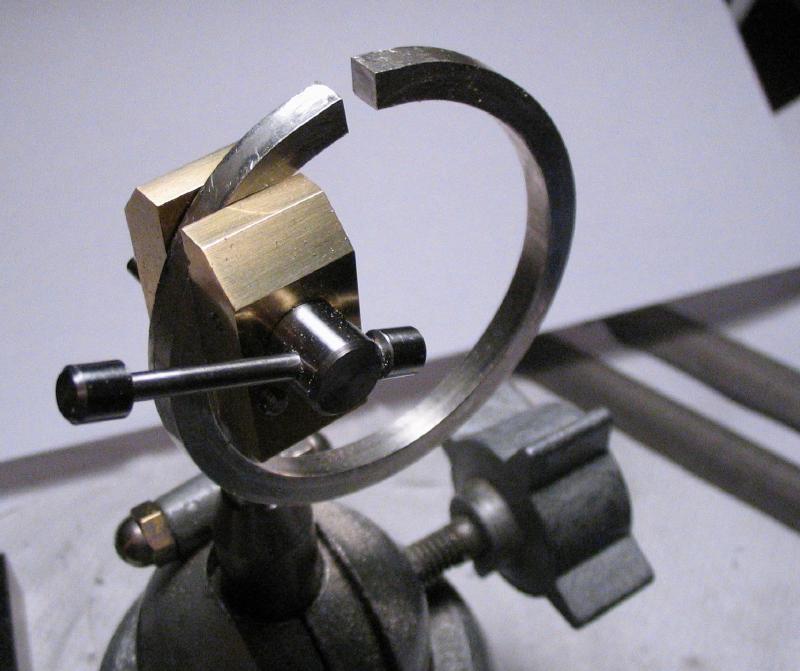
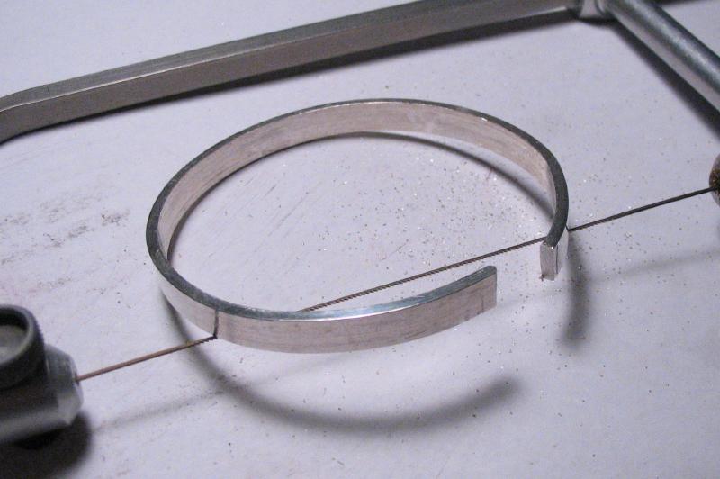
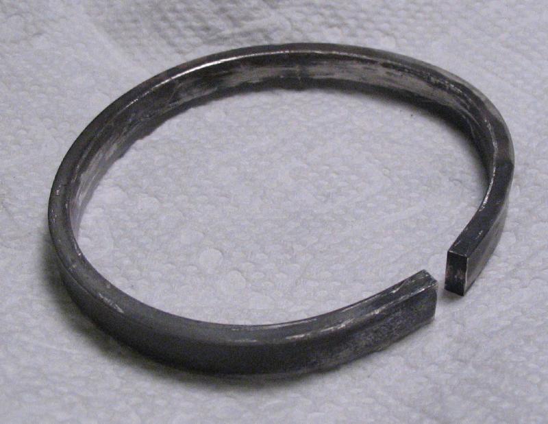
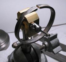
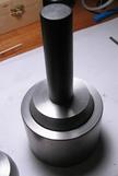
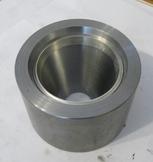
The ring then laid in a drawer for quite some time while I pondered how to continue. Having recently completed the bezel forming tool, the ring was brought back out and placed into the anvil for a quick trial run of the finished tool. The largest of the tapered discs was placed over it, the ram inserted into the disc and it was driven in with several light blows with a 40 ounce "engineer's" hammer (just happened to be the largest hammer on hand). The forming tool worked very well and quickly brought the ring to a circular and flat shape. The ring's dimensions were then reassessed on the stepped former. The diameter was reduced by cutting the ring open and bending it on the former to approximate how much material needs to be removed. A small section was sawed off (the previous solder joint was included in the cut out section), and then the ring was roughly reformed and the ends filed square for soldering closed again.
The band was then returned to the forming tool to make it circular and flat again. The internal diameter was slightly less than 56mm, but this is to be preferred since it will be bored open on the lathe and can be made true in the process.
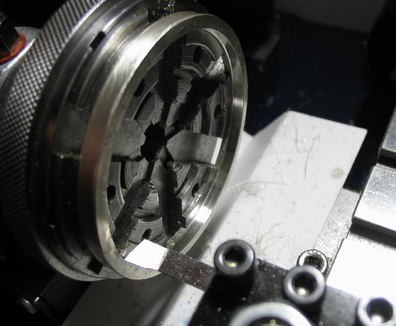
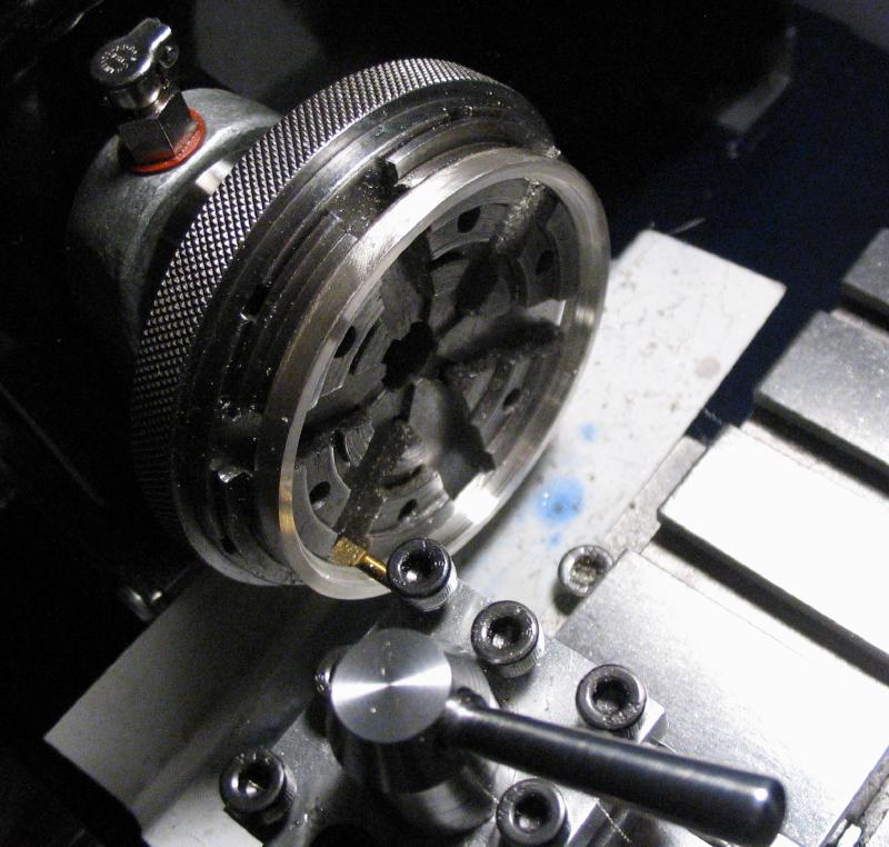
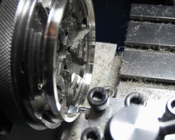
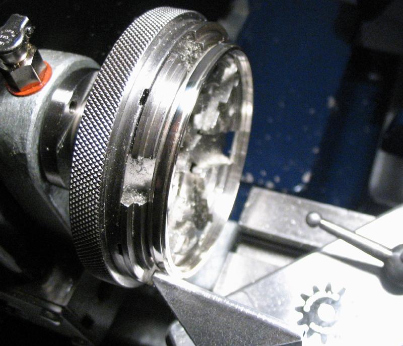
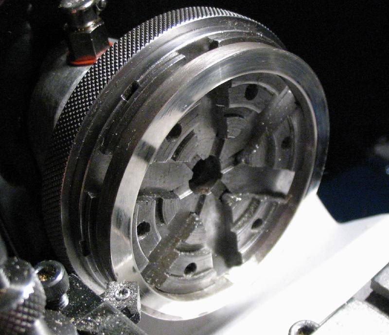
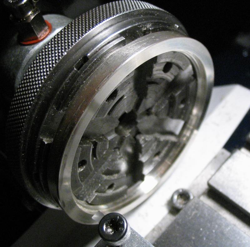
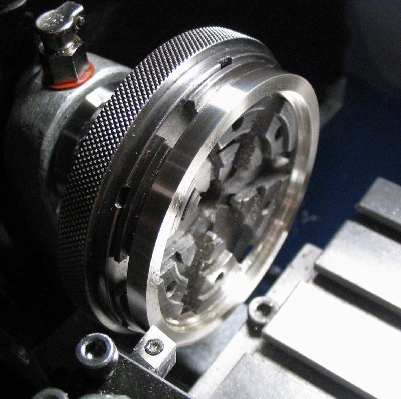
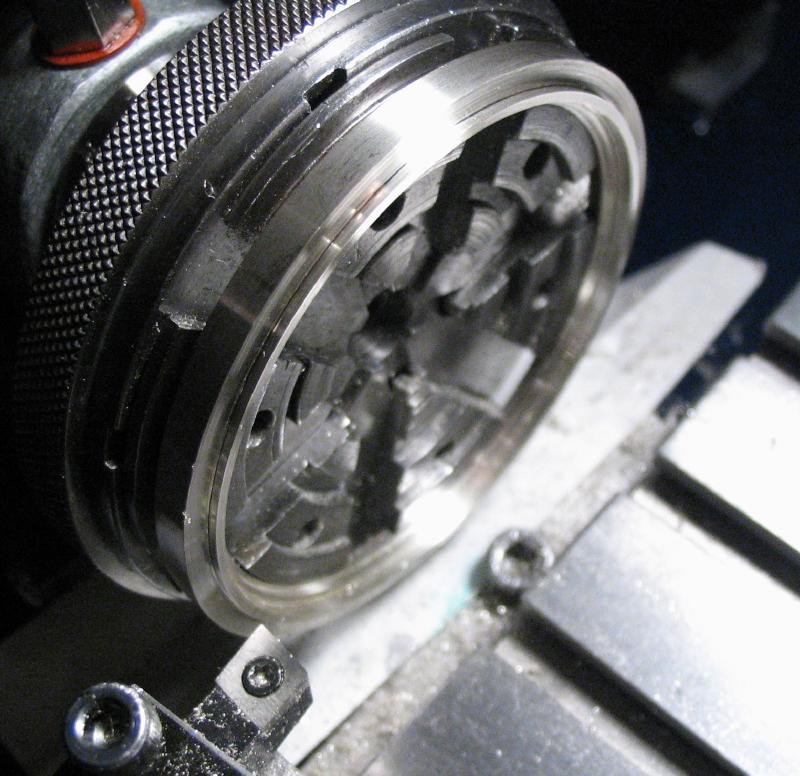
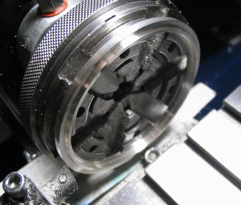
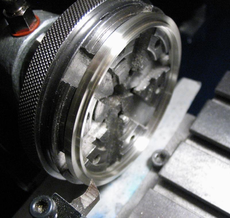
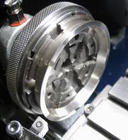
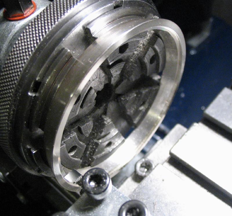
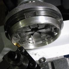
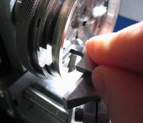
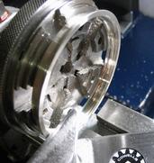
The band was then mounted on the lathe using the six-jaw bezel chuck to grip it internally. The band can then be machined on one of its sides. I am following, more or less, the sequence of operations depicted in figure 683 of my copy of Daniels' "Watchmaking." The band was first bored open to just under 56mm, and the bore is extended as far as the chuck jaws permit, which was about 3mm of depth. The band was then faced to present a true surface (it could have been faced first, of course). The boring was then continued to bring the internal diameter to 56mm, which matches the barrel bridge "diameter," and then counterbored to 58mm for a depth of about 1.5mm to accept the movement mainplate.
Silver does not machine particularly well, however, a sharp tool makes a big difference and cutting oil seems to help with the quality of surface finish. Daniels mentions that turpentine was the traditional cutting fluid to use here, but suggests using modern cutting oil. I happen to be using "Cool Tool II" brand by Monroe Fluid, and have read online that it consists primarily of tall oil, which curiously happens to be another product sourced from pine trees.
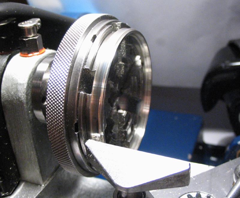
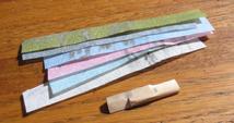
The first snap ring is then turned on the outside diameter of the band, which is about 1mm 'square' with a 7 degree negative taper. The starting step for the snap ring was formed using the cross slide, and then a graver (made from 3/32" GRS Glensteel) and T-rest was used to form the 7 degree angle for the "snap." The graver was also used to true and turn the central portion of the band. This central portion will be a visible section of the finished case that can decorative; it was given a slightly rounded shape. The compound slide was set to 7 degrees and was used to lightly turn the snap ring to assure that the angle formed with the graver was correct; however, the lathe tool could not reach into the corner. The work was given a light polish to smooth all the turned surfaces at this stage using strips of 3M "Tri-M-ite" polishing cloth wrapped onto a small piece of wood that was filed to fit into the various recesses of the case band. I will note that Daniels specifies using water-of-Ayr stone in a similar manner.
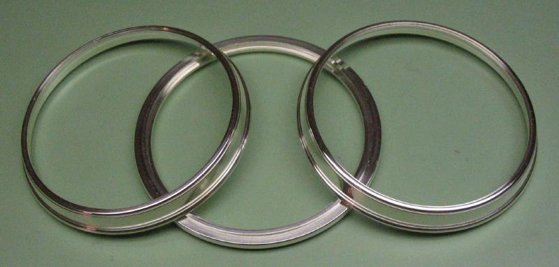
The work was then reversed on the chuck, securing the band by the counterbore formed in the previous steps. The same turning steps above are essentially repeated for the reverse side. The 56mm through-bore was finished; and after counterboring, there will be an internal ring remaining that serves as the movement retainer. The counterbore was formed on this side, and although not a critical diameter, it was made to match the the reverse side (58mm). The second snap ring was turned and the central portion can be finished by hand turning. At this stage, the center band is basically symmetrical. Later, one side will be chosen to receive the bezel for the crystal, and the other side will be fit with the back cover bezel, which will include a hinge.
Although the center band will receive a considerable amount of additional work and therefore need to be refinished later on, I decided to go ahead and polish it with jewelers rouge on a muslin buff wheel mounted in the Foredom.
Unfortunately, as the band was examined to plan subsequent steps, it was quickly observed that there is insufficient landing for the hinge. The starting material for the band was barely sufficient in thickness to begin with, and the thickness was then reduced when the inner and outer diameters were turned true and the latter rounded over. Therefore, the band must be restarted using wire with a larger starting thickness.
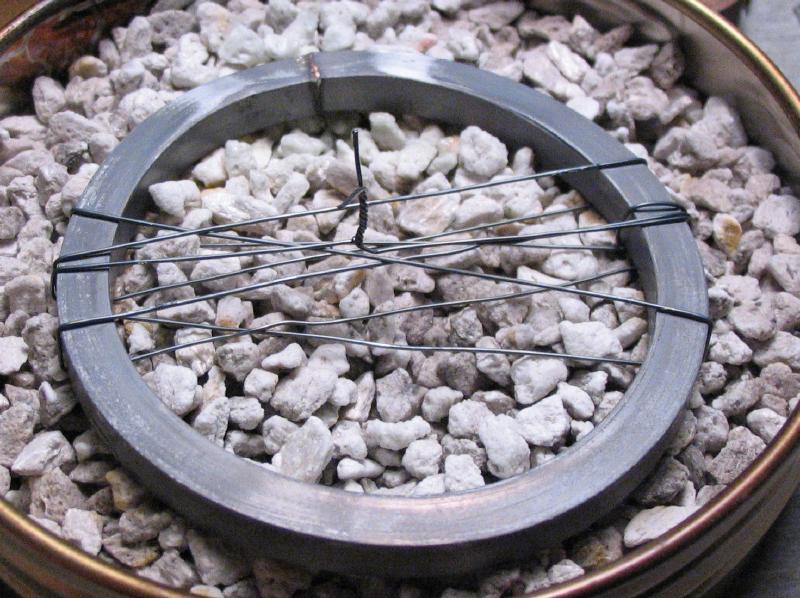
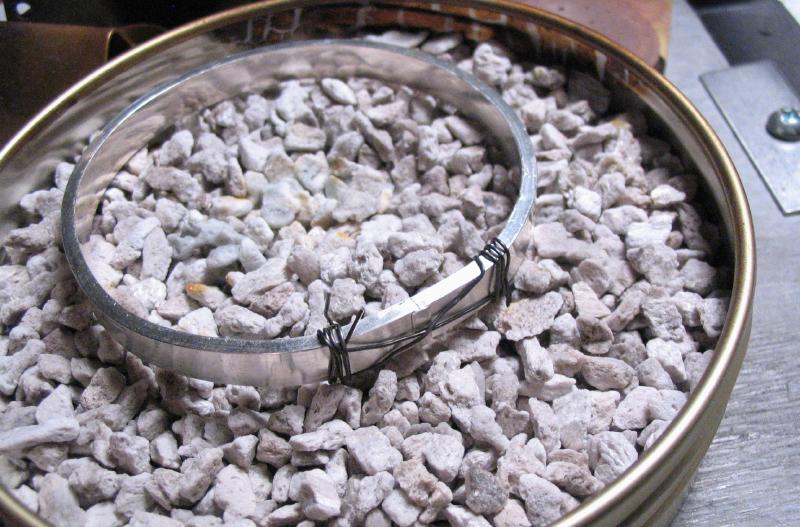
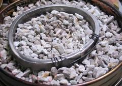
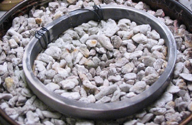
I decided to restart the band using 4 gauge (~5.2mm) square wire. A length of about 192mm was marked and sawed off. It was bent around the 56mm diameter forming rod. The thickness of the 4g wire prevents it from easily taking shape, so this took some patience and a fair amount of force to get the wire bent into a reasonably circular shape. Annealing the wire first would have likely helped. The ends of the wire are filed so that they mate together with no visible gaps when looking at it with a light source behind. The ring can then be soldered closed. I decided to follow a setup shown in Herr Pahlow's book on casemaking. Instead of placing the solder chip on top of the joint, it is positioned between the ends of the wire. A piece of about 5.5mm square was snipped out so that there is little over hang. The band is bound in iron wire to keep everything from moving and the clamping pressure of the silver wire itself helps keep the solder chip in place. The work was heated while on top of the pumice stone, and considerable heat is needed. Once the solder began to flow, heat was directed to the whole ring to bring it up to a red heat. After cooling slightly (no longer red hot), it was plunged into water to anneal the silver. This will make the band more malleable while forming the ring into a circular shape. This is done by placing the band into the bezel forming tool and driving in with a tapered disc to make it circular and also to help make it flat.
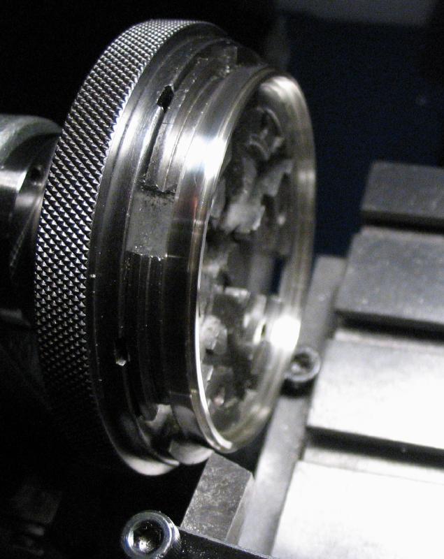
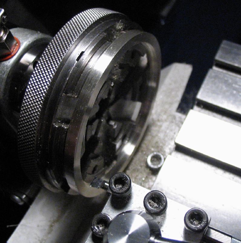
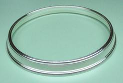
The band was then mounted on the lathe in the 6-jaw bezel chuck to repeat the process of turning shown above for the previous attempt. One change to that method is that the band was faced on one side and then it was reversed on the chuck in order to give a better initial fit to the chuck. After reversing, the second face was also turned true. The 56mm internal diameter was bored to a depth that the chuck jaws allow (3mm), and then counterbored to 58mm to a depth of 1.75mm. Another change, the external diameter was turned true since the full external diameter could be accessed at this time. I left it slightly oversized at this point since this surface will be turned again later after the work is reversed on the chuck.
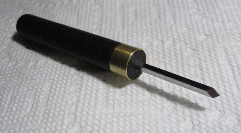
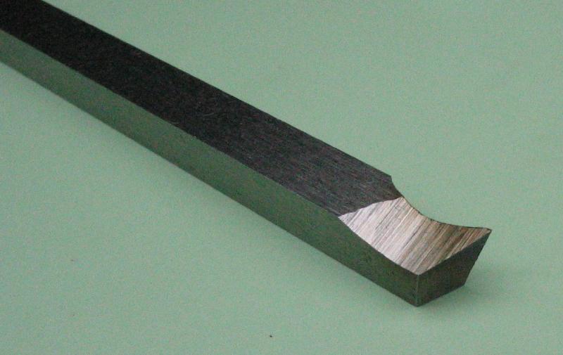
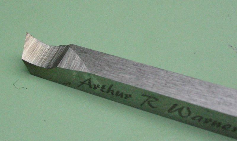
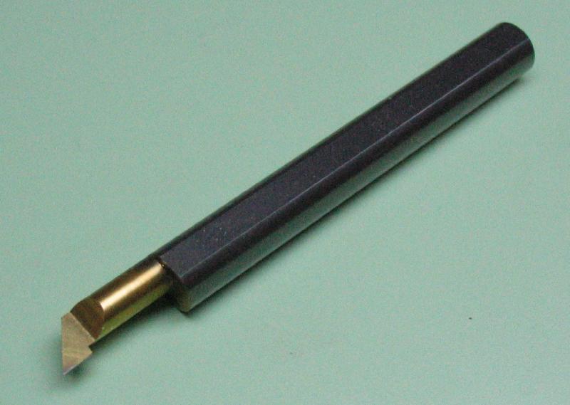
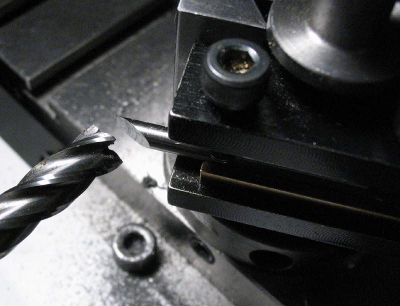
To turn the negative taper on the snap ring of the band I previously used a graver. This was in order to get into the corner, which is hard to reach with the lathe tool bits that were on hand. Instead, this time around a tool bit was specially ground. It has plenty of side clearance, and can fit into the tight corner while using the compound slide set to 7 degrees. I may have given the tool more clearance than is needed, but it worked nicely for this very small step. It was made from 3/16" M-2 high-speed steel (AR Warner).
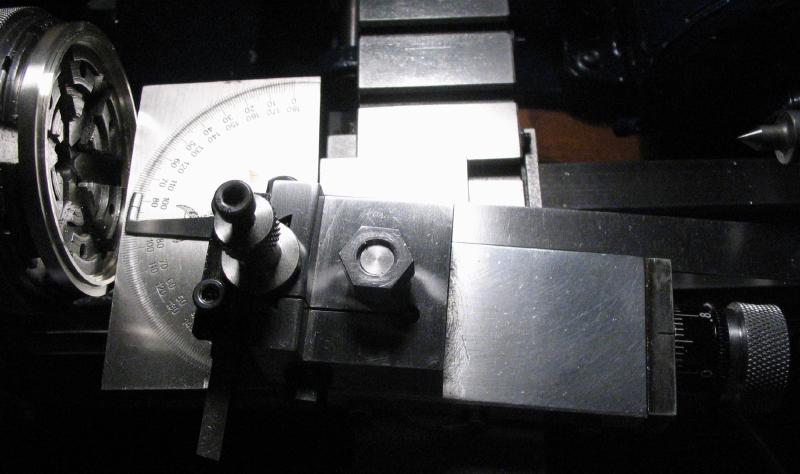
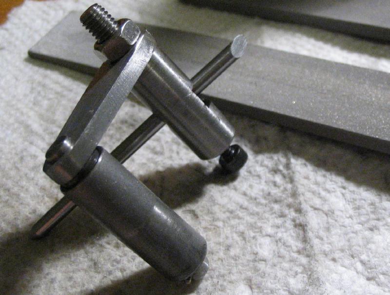
Since the compound slide is graduated in only 5 degree increments, it was set to 7 degrees by using a protractor that is squared against the snap ring face. The slide is aligned with the arm of the protractor and the set screws tightened.
The band can now be reversed on the chuck, and the process above repeated.
The central portion of the band can now be turned, this was done by hand turning. A slight rounded appearance was given to this diameter.
One of the bezels was started before I had determined that the central band needed to be remade. I am leaving the first bezel attempt here, but it also needed to be abandoned and restarted. The required length of material needed was determined using the diameter at the snap ring of the band as a reference. A paper strip was cut out and laid onto 6x2mm rectangular Sterling silver wire, and the length is marked. The section of wire was then sawed off, the wire was roughly bent into a circle, and the ends filed square to provide a clean joint.
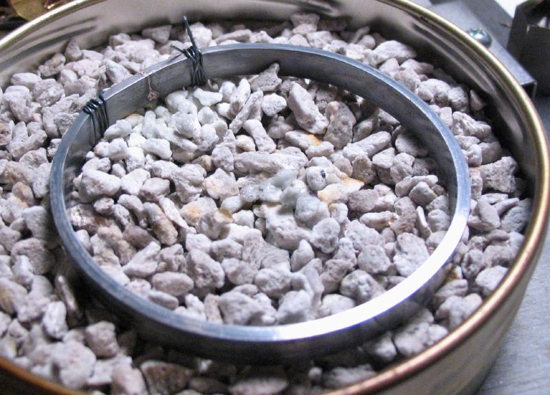
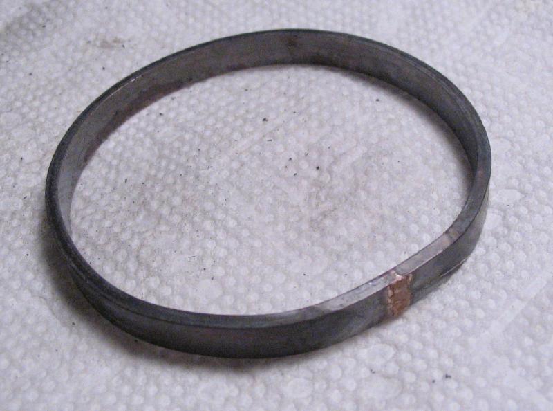
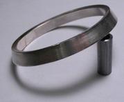
The wire was bent closed, the joint was fluxed and then wrapped with iron wire to help keep the arrangement secure. A chip of hard solder was cut-out and placed over the joint and under the wire to help keep it in place. When soldering the center band described above, I held the work in the 3rd hands of the soldering station, but it was difficult getting the work up to the proper temperature. In order to help conserve heat, I laid the work onto a bed of crushed pumice in a shallow tin. Some of the pumice was arranged around it to reflect the heat, and the work was soldered with a little more ease this time. After the work cooled from redness, it is plunged into water. You can see the residual solder on the joint in the photo, it would be better to use less, but the excess is fairly easily filed away.
The ring was then transferred to the forming tool. First it was made round and circular, flipping the work over several times between blows with the driving disc and hammer. After the ring was circular, one side is chosen as the front and it is driven into the tool to form the angled, bezel shape.
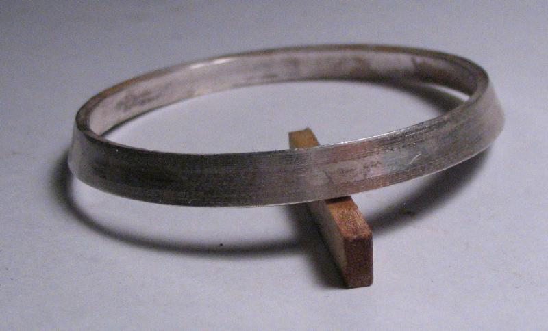
Progress with forming the bezel seemed to slow, so I attempted to anneal the work before continuing. This step was not photographed and involved placing the ring back onto the bed of pumice and heating with the torch until the silver faintly glowed red. The temperature was held for a brief period and the ring was then plunged into water. The ring was wiped off with a paper towel and a dab of Simichrome to remove the oxidation. The forming was then continued and progress monitored by holding the ring against a protractor (set to 20 degrees) to check the angle around the perimeter of the ring. You can see the surface abrasion on the ring where it contacts the bore of the forming tool. Some polishing of the internal bore of the forming tool may help things proceed more smoothly (figuratively and literally).
When the problem with the central band was discovered it was also noted that the unfinished bezel started above would also be inadequate in width as well. So the bezel was also restarted using a thicker piece of rectangular silver wire (7x3mm). The increase from 6 to 7mm was a result of what was available as stock material. It can be reduced later when machining, however, the extra thickness (from 2 to 3mm) will be needed. The methods used above were essentially repeated, however, since the stock wire was quite hard, it was annealed prior to roughly forming the 192mm length of wire into a circle.
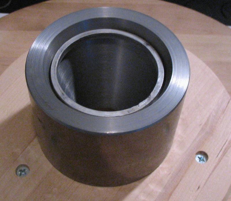
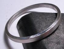
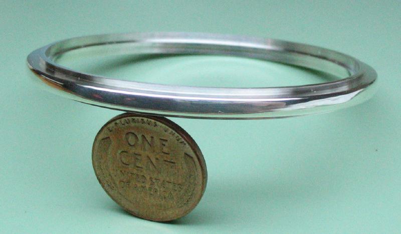
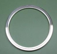
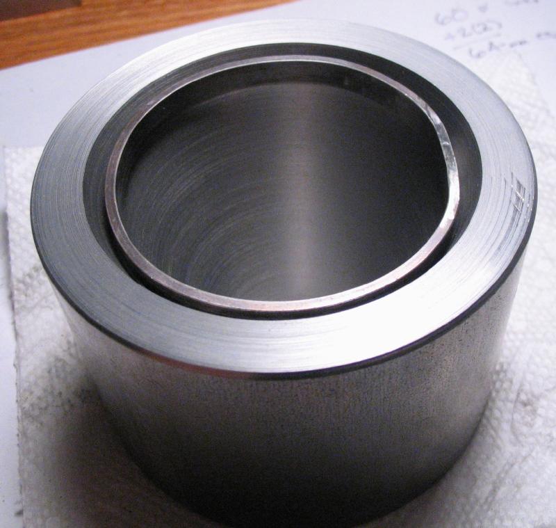
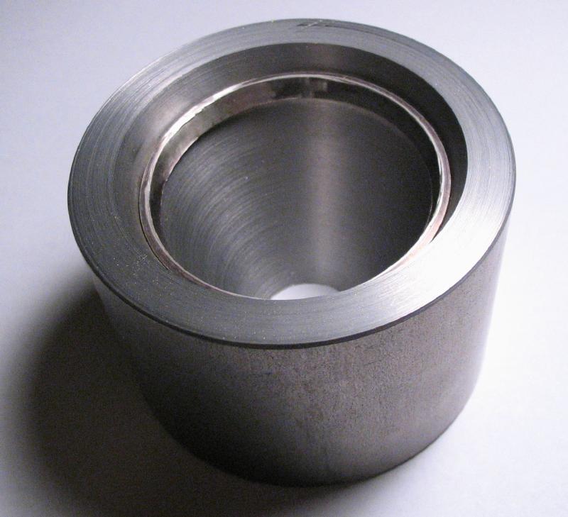
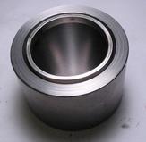
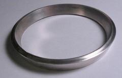
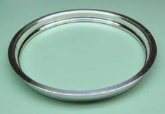
The resulting joint of the bezel ring was filed to remove excess solder, and then the ring was transferred to the forming tool. The bore of the forming tool was polished with emery paper to give a smooth finish, this assisted in the forming process since it offers less friction and leaves a smoother finish on the work. The closest matching diameter discs were used; the one in the photo happens to be the inverted side. The resulting bezel shaped ring is shown, and it can be noted that the front and back edge-faces are somewhat deformed from the process (sloped inward or outward), but these faces will be corrected on the lathe.
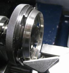
The bezel was mounted on the 6-jaw chuck by gripping it internally. It was first faced down to true the back surface. A groove was then bored which mates with the snap ring of the center band. The groove is about 1mm deep with a 7 degree taper. The center band should be a tight, snap fit to the bezel, which can be tried as the boring progresses. I am using here a stock Micro 100 boring bit, which are specified to have 2 degrees of tip clearance and 6 degrees of side clearance. This only leaves about 0.5 degree of clearance on either edge while boring the groove. It worked but with very light cuts.
The bezel is reversed on the chuck by gripping internally in the snap groove just made above. The bezel is bored open to 56mm, which will match the diameter of the dial (both bezels will be made the same). The front edge can then be faced true as well.
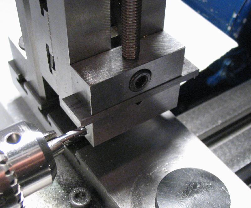
The groove for the crystal was bored using a modified carbide boring bar. The Micro100 BB-200500 boring bar was due for resharpening from previous use, but it was re-purposed by grinding on a diamond wheel to reduce the front edge clearance. The final included angle is about 50 degrees. The rim of the 25-11/16 ligne (57.9mm) VTF crystal that was selected has a 56.5 degree taper at its edge. I was uncertain what sort of groove is typically used for these crystals, but I decided to bore a tapered groove that mates with the taper of the glass (33.5 degrees). The groove was bored to a depth of 0.5mm and to a full diameter that matches the crystal. This latter dimension cannot be easily measured, so the cross slide dial must be used with careful observation. The crystal appears to be a very tight fit, unfortunately, I will have to wait until much later before I discover whether this groove needs to be modified.
The side of the bezel was then turned using a graver and the T-rest. There is plenty of opportunity here for artistic interpretation. The full diameter was retained at the snap ring edge and rounded over with a thin step. The forward portion was turned down, and the front edge was rounded over with a small step.
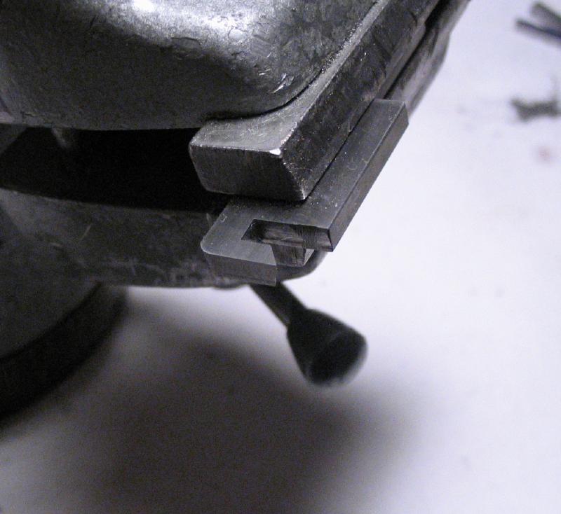
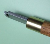
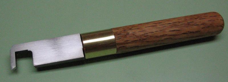
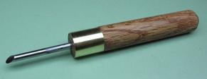
Daniels describes a graver for turning the internal dimensions of the bezels, and suggests its fabrication from an old file. The process is not given in his book, but this would require an "old" file, which would have to be annealed prior to modifying it. Instead, I attempted to make this tool from oil-hardening flat-stock tool steel (1/2" x 1/8"). About 2" of material was mounted in the machine vise, and the ends milled flat. The basic dimensions of the working end were then milled using a 1/8" endmill. A tang was formed by sawing with the piercing saw. The cutting edge was formed using a #2 hand file while holding the work in the bench vise. The edge was smoothed flat with a India oilstone slip prior to hardening the graver in oil. After hardening, the cutting edges were dressed with India oilstone followed by an Arkansas stone slips.
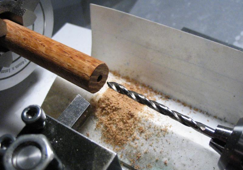
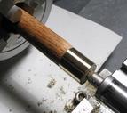
A handle was made from a length of 1/2" oak dowel rod. The back end was chamfered to give a rounded appearance. The rod was then reversed in the 4-jaw chuck and roughly centered. It was drilled with a 1/8" wood bit, and then turned down to friction fit a collar, which consisted of a short piece of 1/2" brass tubing. The collar was tapped on with a mallet and then trimmed down flush with the end of the handle on the lathe. The graver tool bit was held in the vise and the handle tapped onto the tang.
After some experimentation with the graver, it was found to not have quite enough reach. Another one was made in the same manner but with an increase in the cut out space, and a little longer in length.
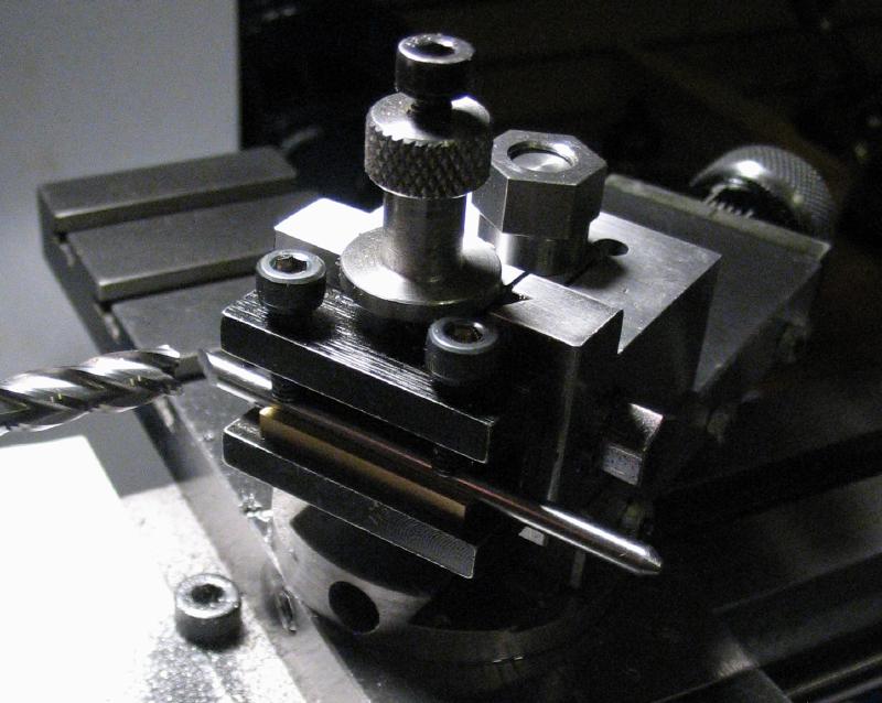
Another graver was made to assist in turning the internal space of the bezel. This one is simply made from a piece of 1/8" O-1 drill rod. It was mounted in the lathe tool post with the compound slide set to 30 degrees. A cutting face was milled, and then mounted in the graver honing jig to smooth with a file. The graver bit could then be hardened in oil. Another handle was made from 1/2" oak dowel and the bit installed. The final cutting edge was finished on an oilstone.
The internal portion of the bezel is turned to lighten the weight and provide space for the movement plate or movement components (i.e., front or back bezel). Generally, the bore was opened to about 58mm and then curved towards the seating for the crystal. The round graver was the most useful in this endeavor.
The first bezel completed and ready for finishing...
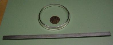
The second bezel is made by the same method as above and is made to essentially the same dimensions. Shown is the bezel above next to the length of silver wire that will be used to make the second bezel.
There were a couple changes to the procedure when making the back bezel. Another Micro100 boring bar was ground to provide more clearance when turning the snap groove to fit the center band, as this was a tight fit previously. In addition, the groove for the case back is a 10 degree taper to a depth of abut 0.7mm instead of the more acute groove that was turned for the crystal-holding bezel above.
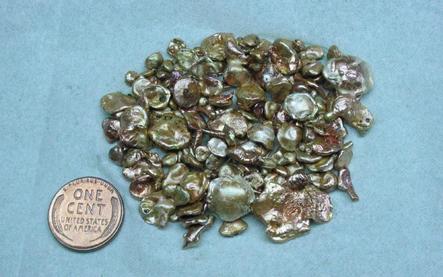
Whenever machining silver, the lathe is cleaned up beforehand so that the silver swarf produced can be gathered up afterwards and be free of other metal debris. The swarf has cutting oil and other oils and in a form not easily to work with. It was melted down in batches outside in a melting crucible (see the pendant page for some additional information) and the molten silver drizzled into a metal bucket of water. The droplets of silver solidify as they fall through the air and water, and result in interesting shapes. The silver oxidizes slightly, which is why it appears somewhat brassy looking in the photo below. These pieces will be easier to work with when casting another project. The pile below was formed from the scrap collected while making the bands and bezels above (including the incorrectly made ones) and totaled about 67 grams, which is expensive scrap and worth gathering up.

