A setup for vibrating hairsprings ...
A variety of different methods for "vibrating a hairspring" are described in the literature. The simplest method involves holding the spring with tweezers and suspending the balance wheel that is set oscillating and the rate found by stopwatch or the work preformed over the face of a running pocket watch to count and time the balance oscillations. There were tools designed specifically for this process and the rate of the hairspring and balance is compared to an internal reference balance wheel that is under glass. These are no longer manufactured as far as I know, but can be found on the second hand market under names such as hairspring vibrator or comparator, vibrating tool, or "Luthy tool" (referring to the manufacturer, E. Luthy-Hirt of Bienne). Electronic timing methods can be substituted for visual comparison and timing by hand & eye altogether.
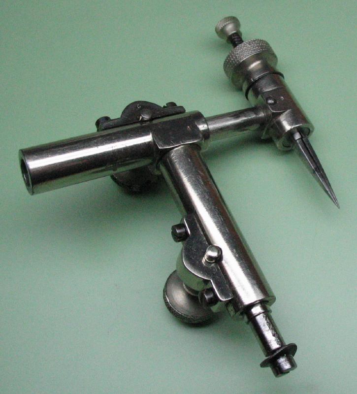
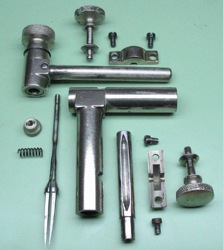
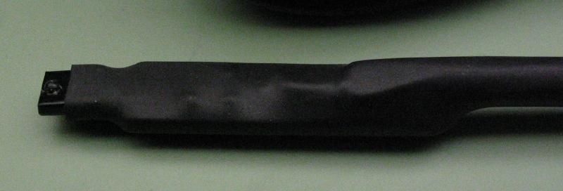
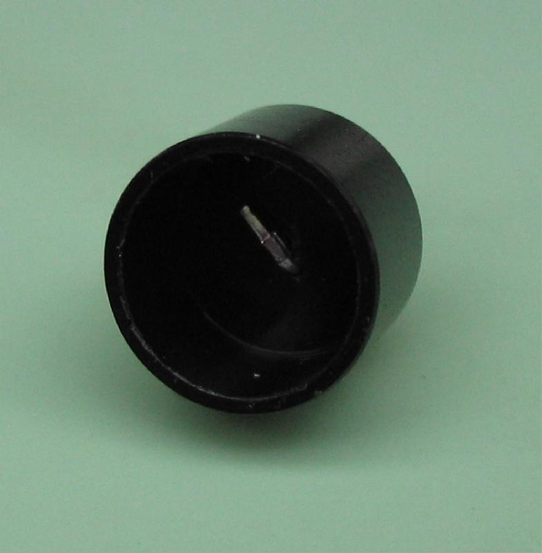
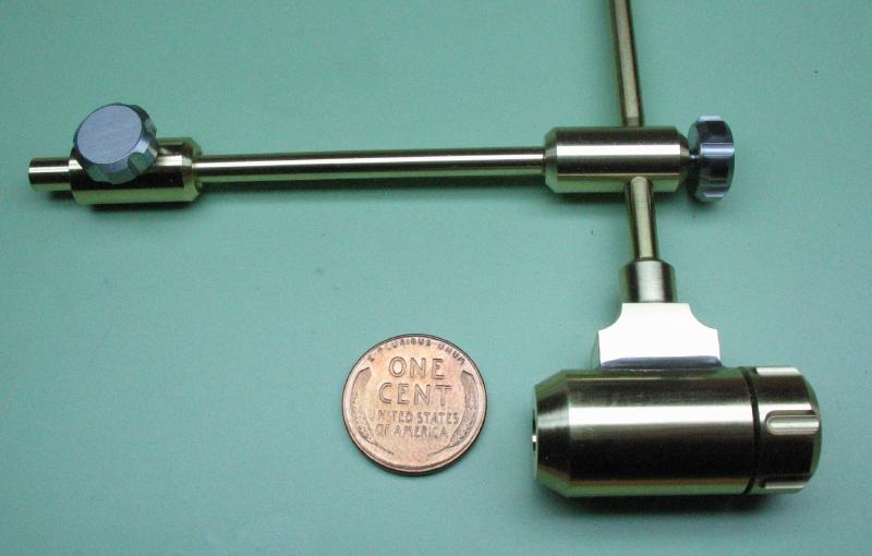
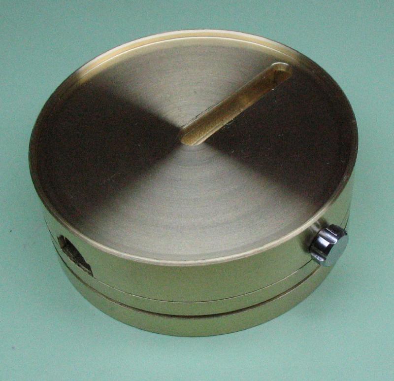
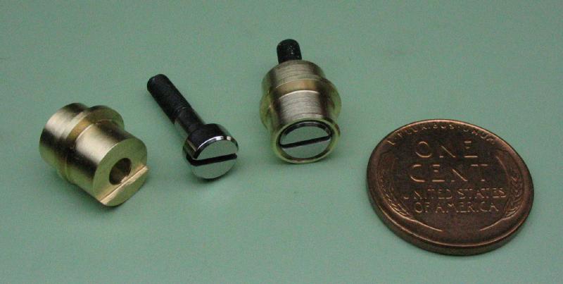
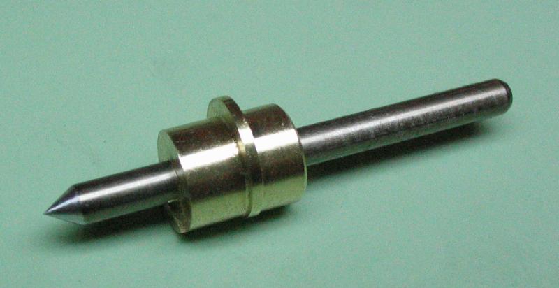
This project began when I acquired a component of one of these vintage hairspring vibrators. It is only the adjustable arm with spring-loaded, rotatable pincer, and the rest of the tool was apparently missing. It was a low bid on ebay that apparently didn't have much other interest, so it came into my possession without much of a plan for its use. The manufacturer is not marked on any of the components, and I did not find any with similar looking construction when browsing the internet. It functions in the usual manner, with a height adjustment and an arm length adjustment. The tweezer/pincer is opened by depressing the spring loaded plunger, and it can be rotated. I disassembled it to basic components and gave everything a good cleaning. The rotating sleeve bearing for the tweezer/pincer assembly appears to be fixed into place with a pin. After a few good efforts to drive the pin out without success, I decided I would rather not chance damaging it and cleaned it by flushing with WD40 and then gave it a liberal oiling with Nye Oil. A surprisingly large amount of grim came out and the works were freely rotating afterwards. The length adjustments are a bit finicky; there are vee grooves that mate with small saw-like discs on the shaft of the knobs. One is fairly well worn and the other still has the light serrations at the edge of the disc. The covers are screwed on and apply the necessary pressure for it to work. Perhaps due to wear, the screws need to be tightened just so for the length adjustment knobs to turn smoothly (or at all) and yet still hold their positions securely.
This project began when I acquired a component of one of these vintage hairspring vibrators. It is only the adjustable arm with spring-loaded, rotatable pincer, and the rest of the tool was apparently missing. It was a low bid on ebay that apparently didn't have much other interest, so it came into my possession without much of a plan for its use. The manufacturer is not marked on any of the components, and I did not find any with similar looking construction when browsing the internet. It functions in the usual manner, with a height adjustment and an arm length adjustment. The tweezer/pincer is opened by depressing the spring loaded plunger, and it can be rotated. I disassembled it to basic components and gave everything a good cleaning. The rotating sleeve bearing for the tweezer/pincer assembly appears to be fixed into place with a pin. After a few good efforts to drive the pin out without success, I decided I would rather not chance damaging it and cleaned it by flushing with WD40 and then gave it a liberal oiling with Nye Oil. A surprisingly large amount of grim came out and the works were freely rotating afterwards. The length adjustments are a bit finicky; there are vee grooves that mate with small saw-like discs on the shaft of the knobs. One is fairly well worn and the other still has the light serrations at the edge of the disc. The covers are screwed on and apply the necessary pressure for it to work. Perhaps due to wear, the screws need to be tightened just so for the length adjustment knobs to turn smoothly (or at all) and yet still hold their positions securely.

|
|
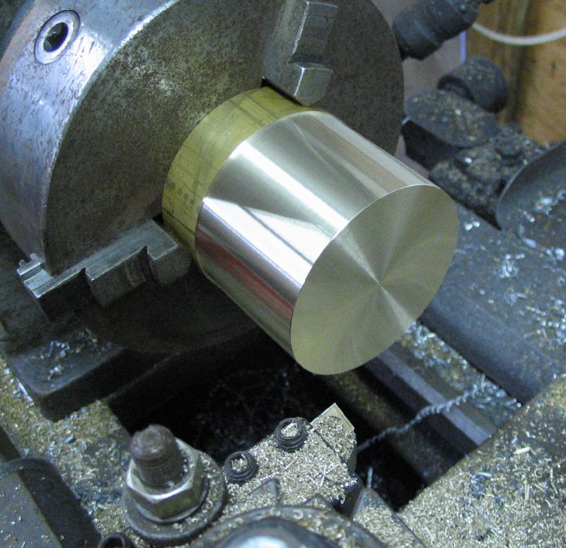
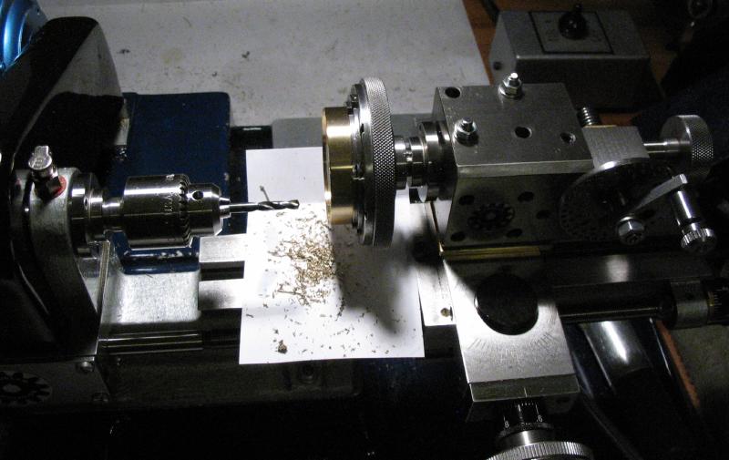
I decided to make a base that somewhat emulates the base of a traditional vibrating tool, and this helps utilize the salvaged arm above. The base was made from a length of 2-3/4" brass (type 360) that was left from another project. It seemed to be a gratuitous use of such a large piece of brass, but it provides a robust and solid base to build upon.
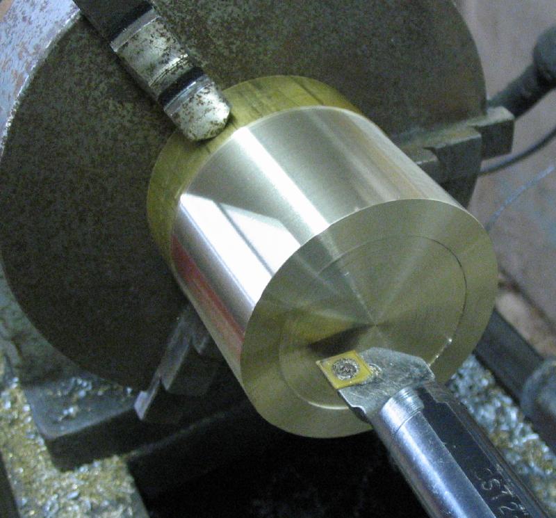
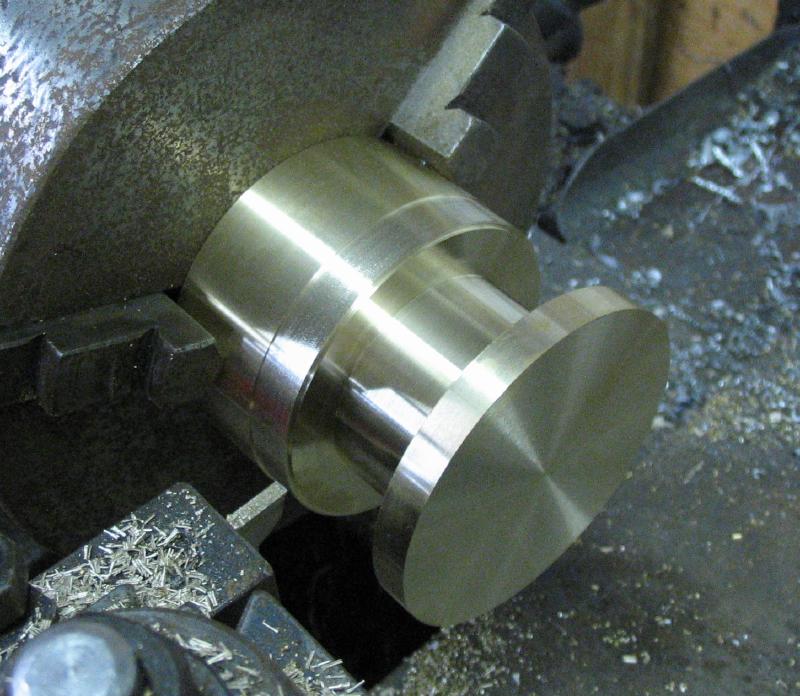
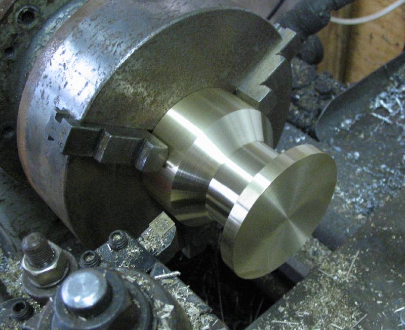
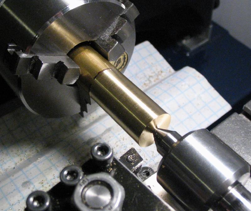
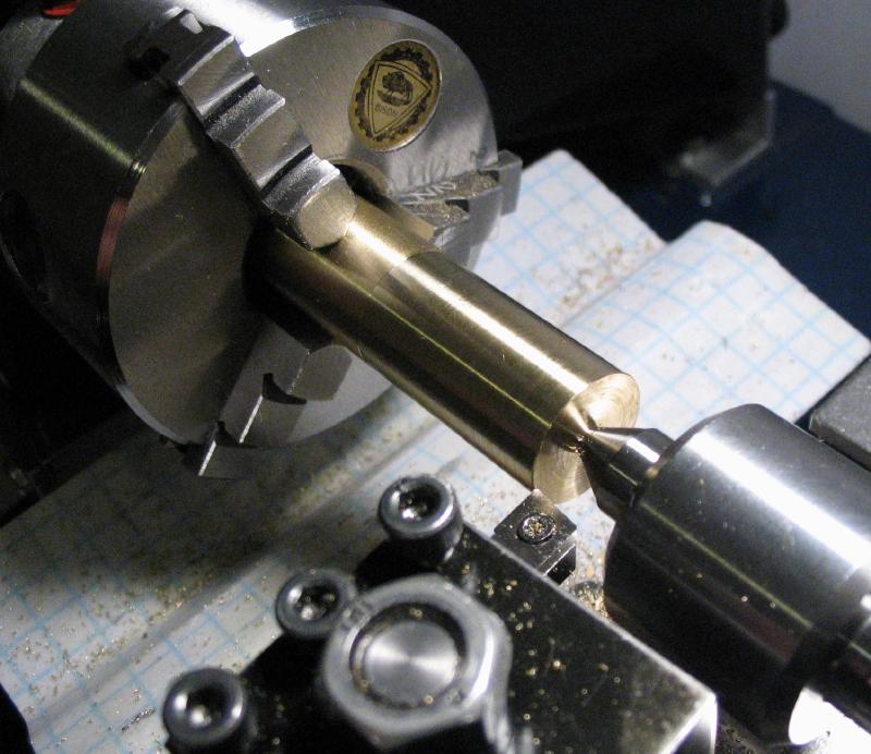
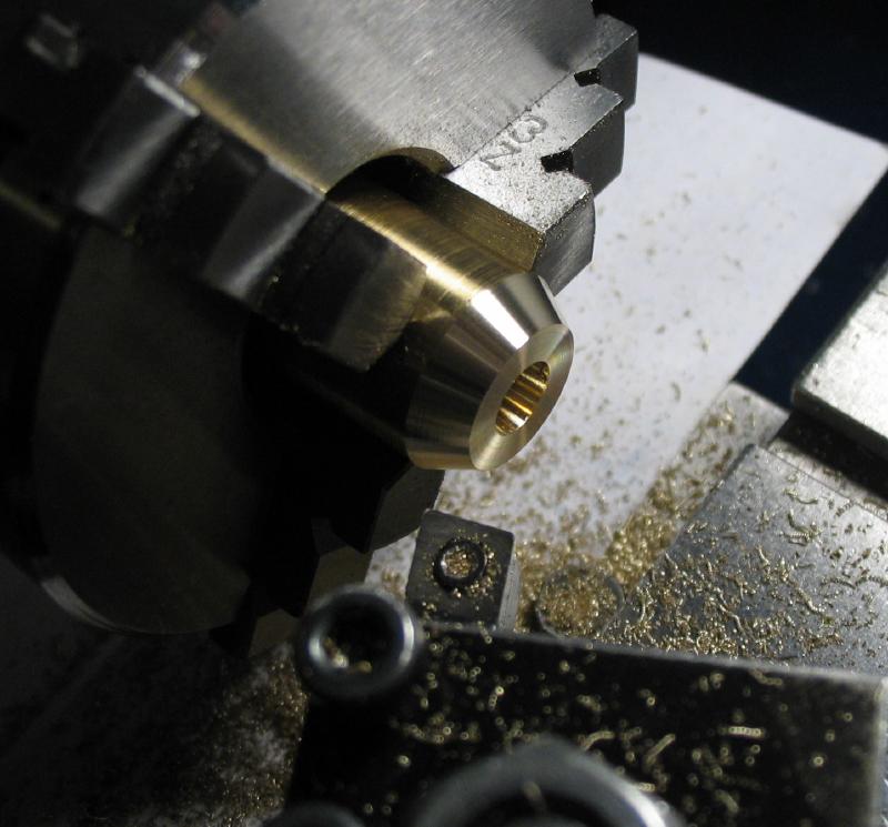
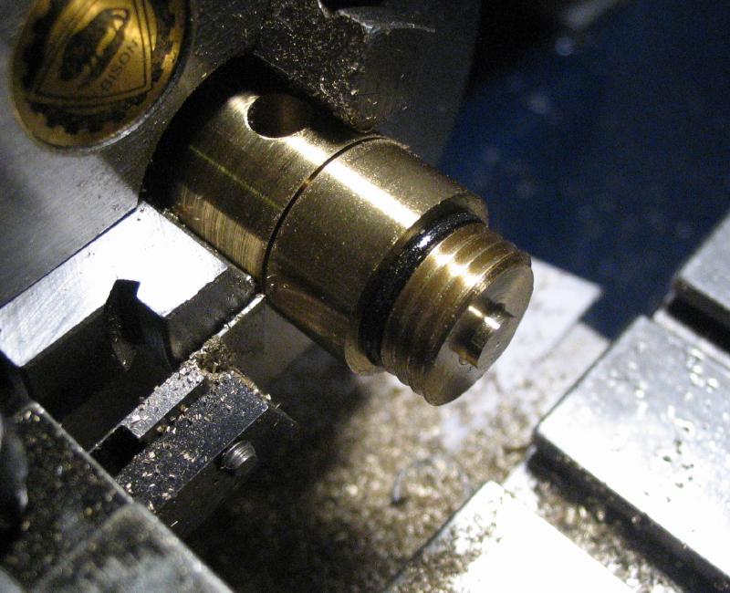
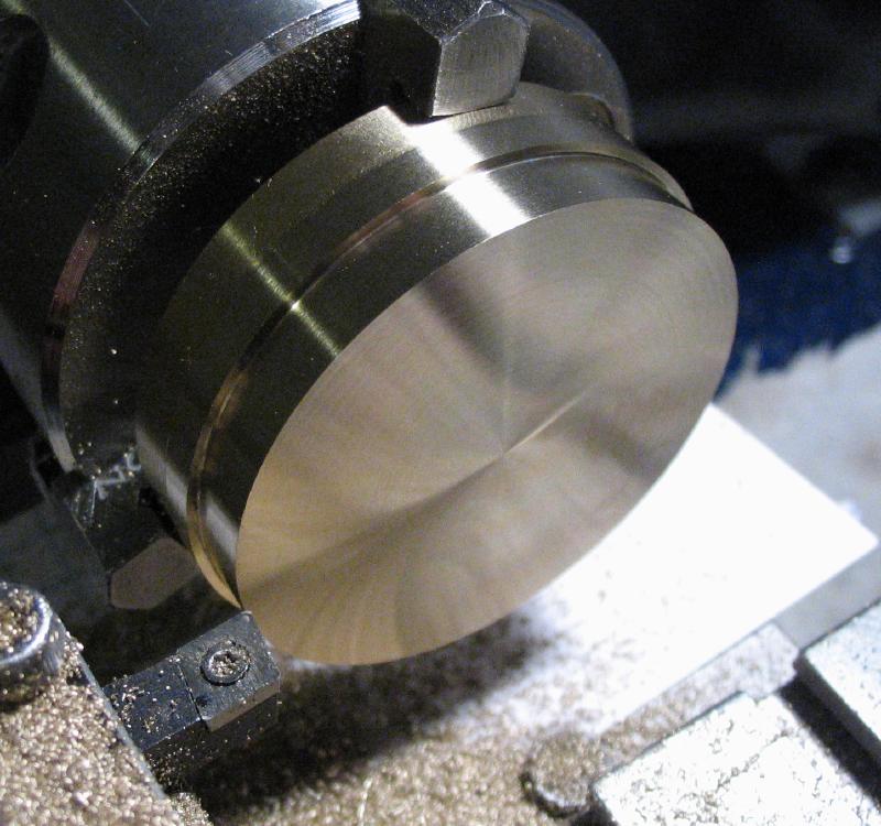
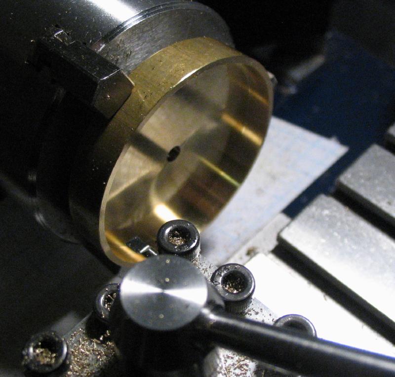
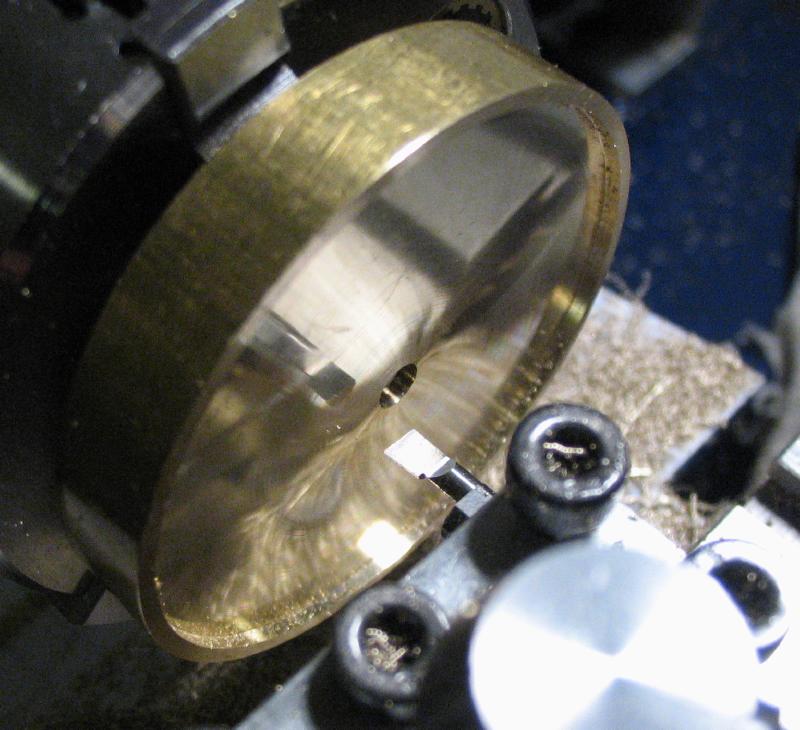
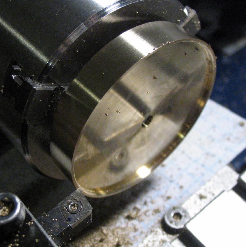
The length of brass was faced and turned true on a Monarch 10EE lathe in a 3-jaw chuck. A small recess was turned since this face will ultimately be the bottom of the base and will help ensure that it doesn't wobble. The work was then reversed in the chuck and faced. The diameter was turned true, and a parting tool used to form a waisted section (about 44mm diameter). The compound slide was used to chamfer the lower corner to a 45 degree taper that just about meets the waisted portion.
|
|
|
|

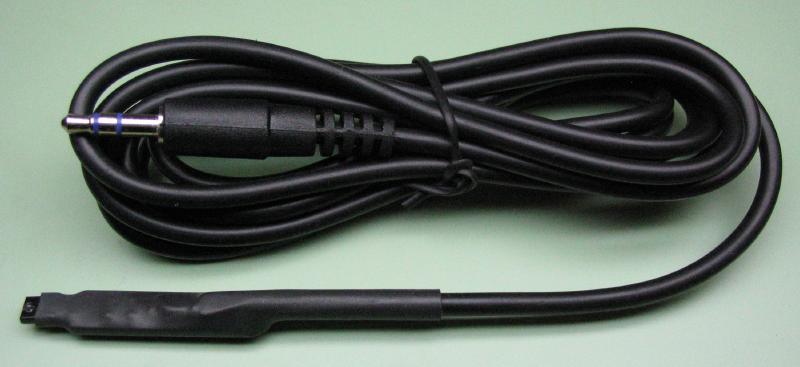
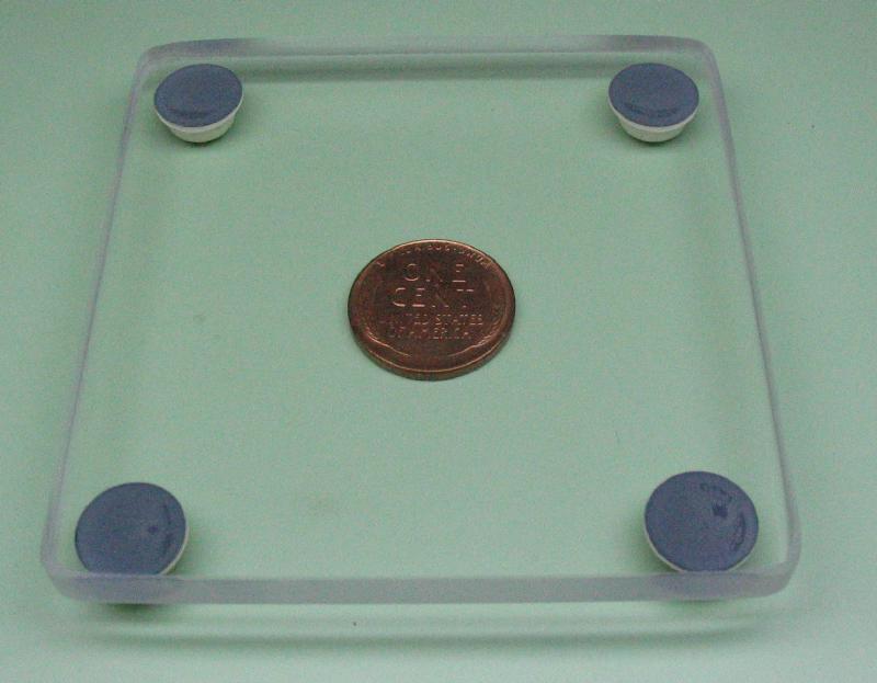
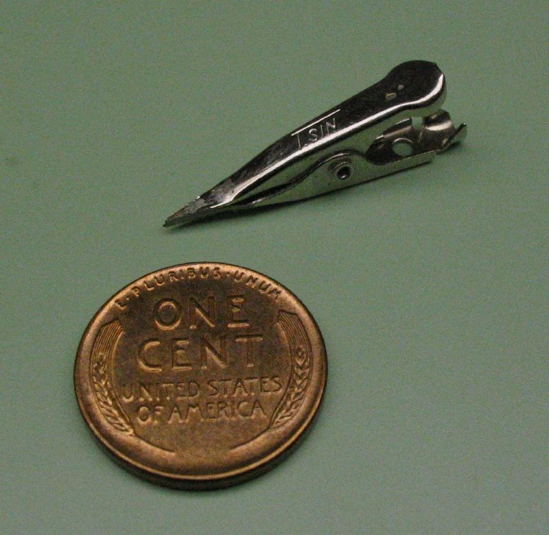
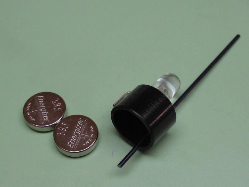
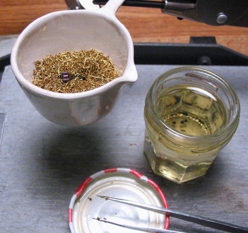
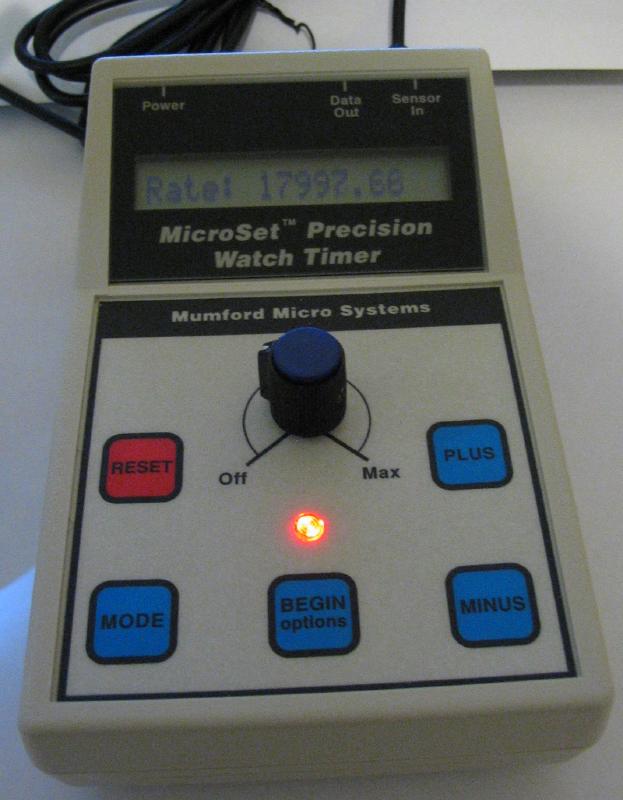
Instead of a reference balance to make comparisons with, I am planning to use Bryan Mumford's (Mumford Micro Systems) sensor for the Microset watch timer. I was tempted to cut the heat shrink off to investigate what the sensor is constructed of, and to perhaps rewire/reconfigure the sensor to be better incorporated it into my project, however, I decided to use the sensor as it is supplied. It is an optical sensor and is intended to be used with a light source. The arm(s) of the balance wheel casts a shadow as it rotates back and forth, and this alternating shadow and light triggers the sensor and the rate is calculated by the Microset timer. As part of the hairspring sensor kit, Mr. Mumford includes a clear plastic base with rubber feet that allow the sensor to be placed underneath and a small alligator-type clamp that has been sharpened to a point. Combined with a "third-hand" of the user's choosing, the setup and a Microset timer can be used for analyzing the rate of a hairspring and balance. The instructions sheet includes a statement that the setup is to be considered experimental, and I had already committed to the construction of the more complicated setup described on this page before even acquiring the sensor. I imagine the included setup would work just fine...
|
|
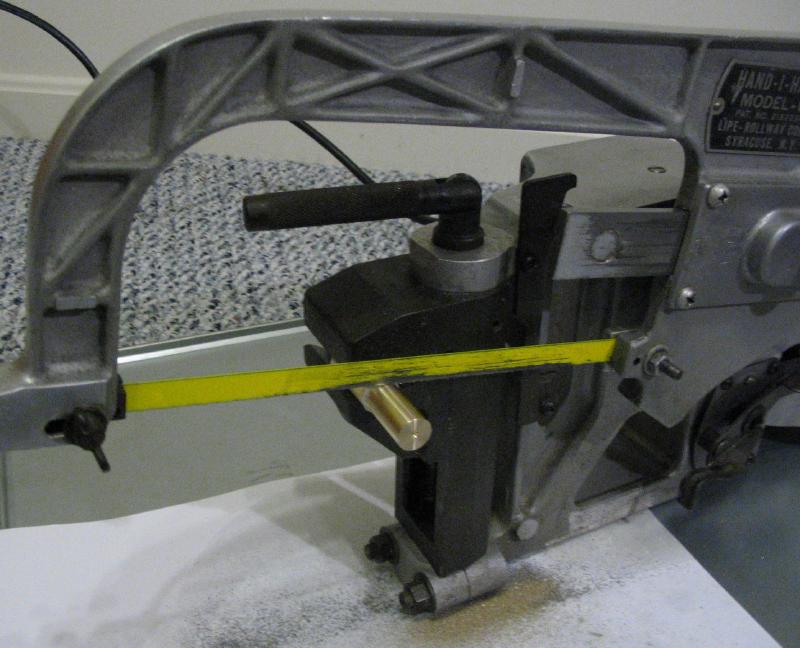
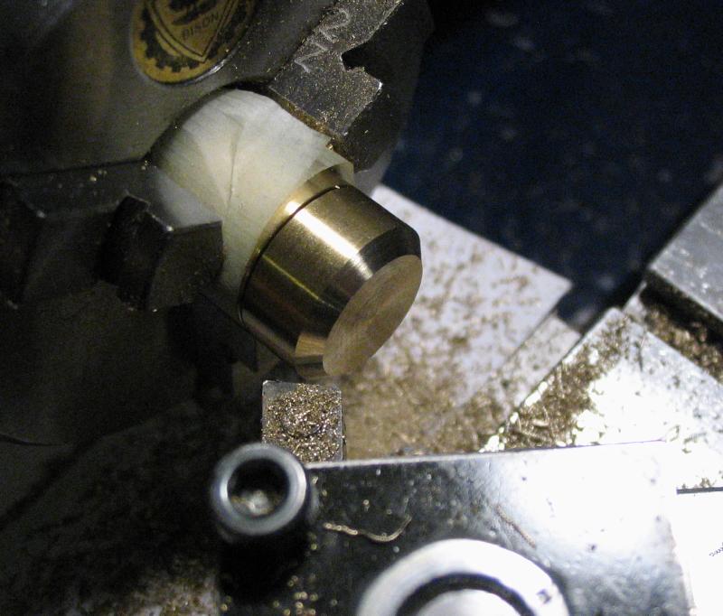
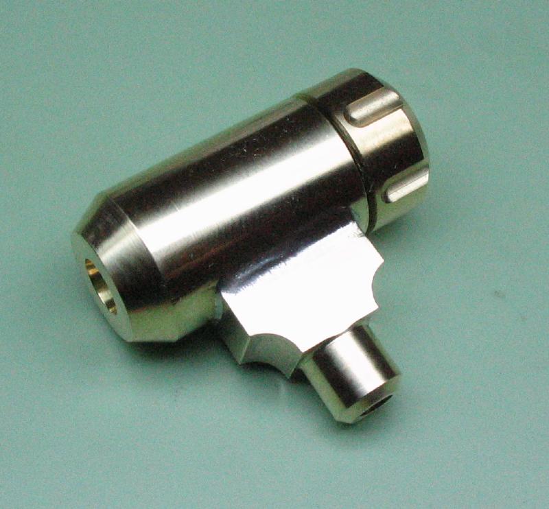
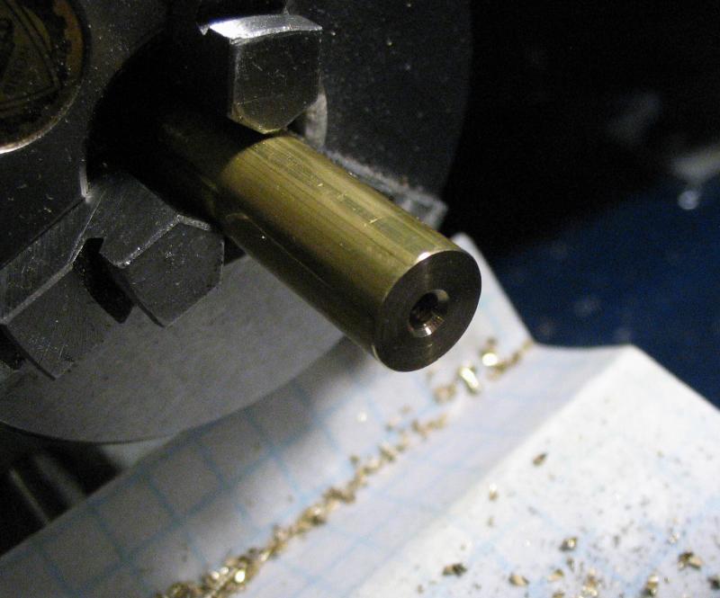
A lamp was made to provide a consistent light source for the optical sensor. I am following the basic design for a mini LED 'torch' (English for 'flashlight') described by Divided Head and found on Instructables.com. I made some changes to the dimensions to suit the material or tooling available. About two inches of 5/8" brass was mounted on the lathe and turned true with tailstock support. The end that will form body of the lamp was turned down to 15.5mm. The bar of brass was then parted on the hacksaw.
|
|
|
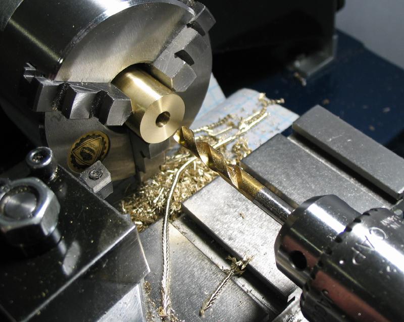
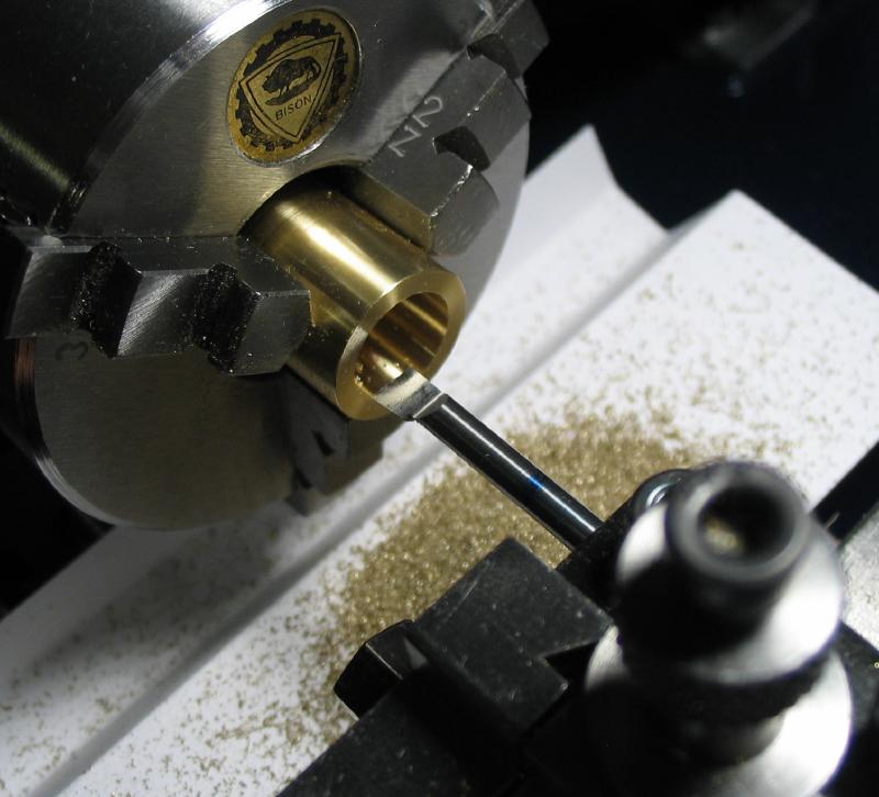
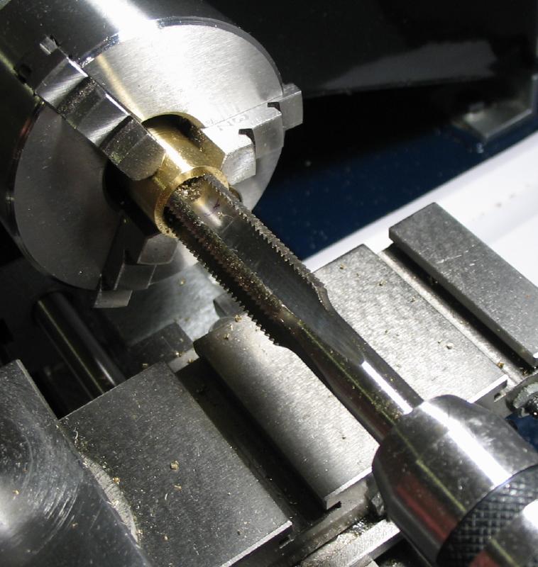
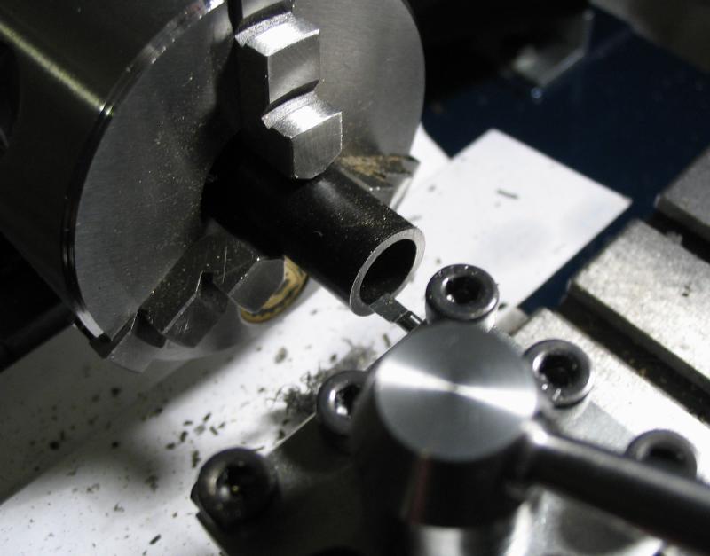
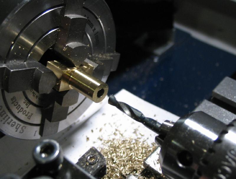
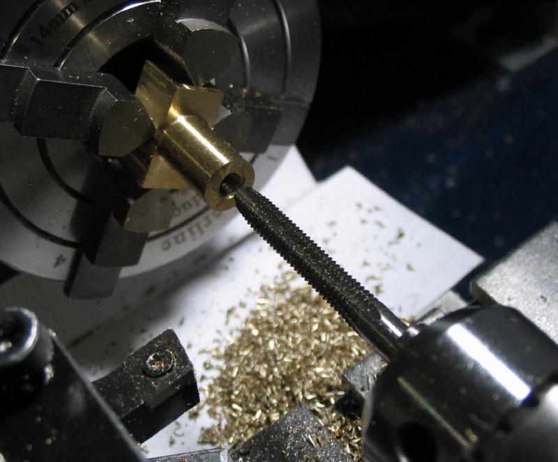
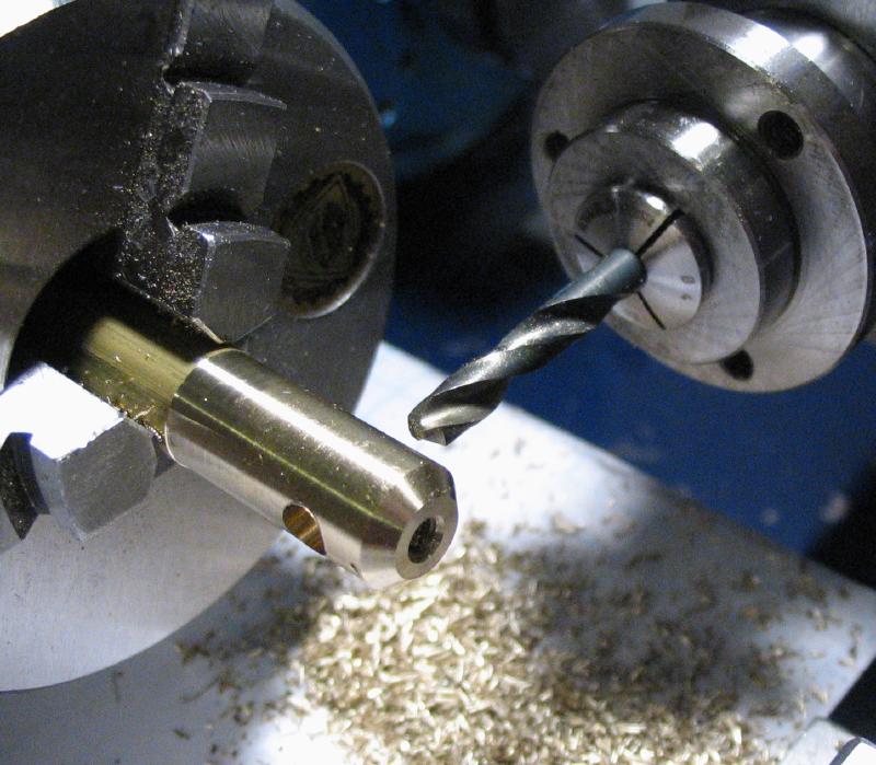
The lamp body was faced down to a length of 25mm and then drilled through 4.9mm and reamed 5mm. A boring bar was used to bore the body out to a depth of 16mm and a diameter of 11.5mm (29/64") to then tap 1/2"-20 NF. The end was counterbored for an o-ring (13mm outer diameter and 1.5mm thick).
|
|
|
|
|
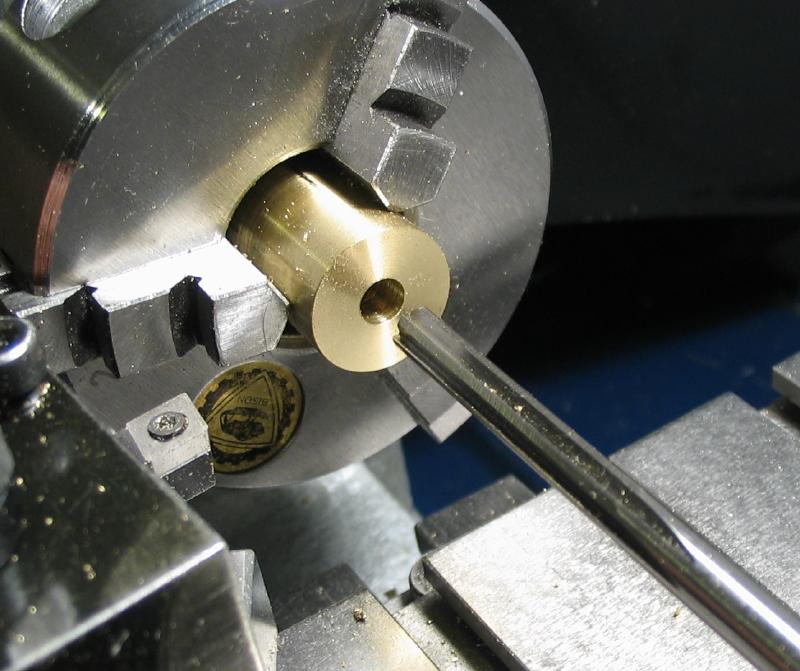
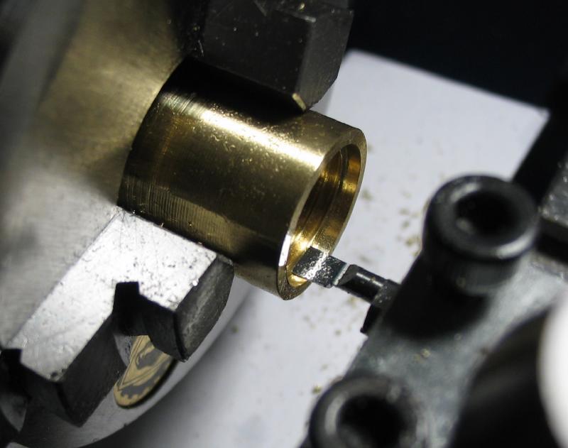
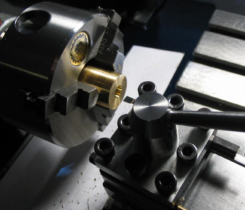
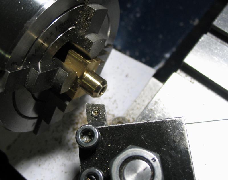
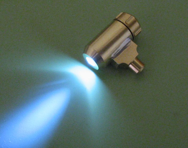
The work was reversed and the LED port was bored open to an included angle of 15 degrees to match the LED's specified viewing angle. The corner was given a generous 30 degree chamfer.
|
|
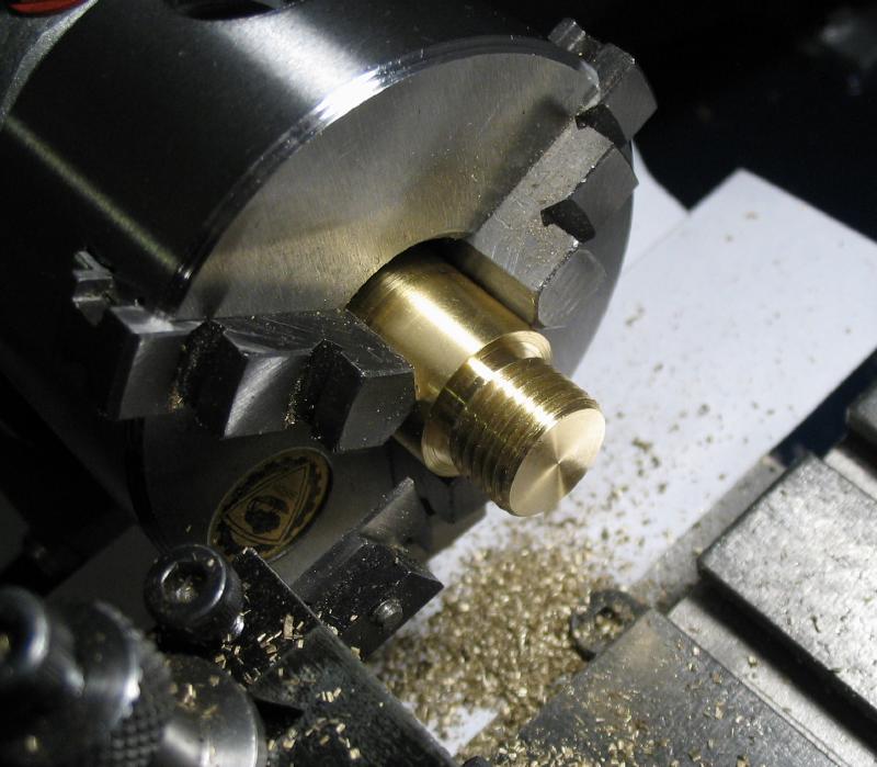
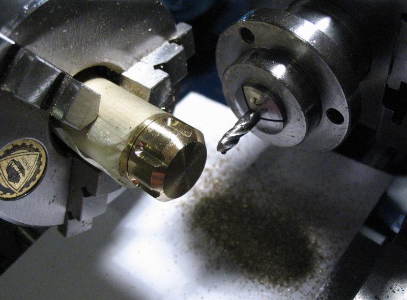
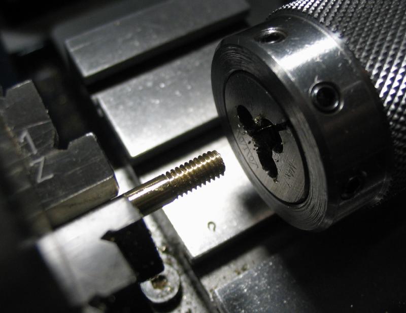
The other end of the 5/8" brass rod that was sawed off was mounted on the lathe to form the lamp cap. The rod was faced true and turned down to 12.7mm and then threaded 1/2"-20 NF using a die. I tried to do this using the tailstock die holder, but the force necessary seemed a bit excessive. A small start was accomplished, however. The work was removed and cross drilled 5mm. A piece of 5mm drill rod from the junk bin was used as a tommy bar to crank the work into the die and finish the threading.

|
|
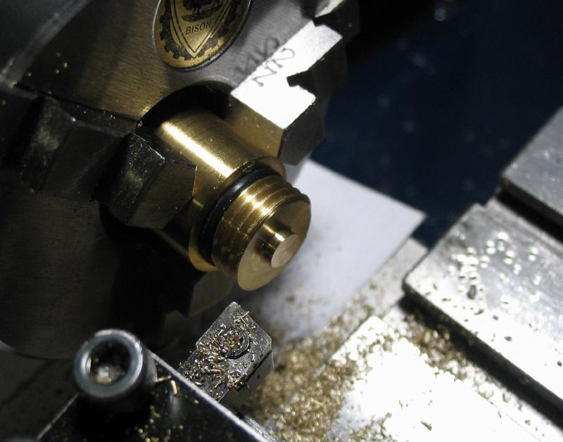
The cap was returned to the lathe and a groove turned using a parting tool to fit the o-ring mentioned above. A short section (3mm to start) was turned down to 9mm diameter to make good contact with the battery face (9.5mm diameter) during its test fitting.
|

|
The electronics housing was made from a length of 1/2" Delrin (acetal) rod. It was faced and bored out to 9.5mm diameter and to a depth of 5.9mm. This is to accommodate the 0.5mm thick LED lead and two SR927 silver oxide batteries (9.5mm x 2.7mm). The batteries are 1.5 V each and the LED is rated for 3 volts, the choice of battery was otherwise due to having some Energizer 395 on hand.
It was then turned to 11.1mm to fit easily in the bore of the lamp body, and parted off for a length of 8mm. The work was then reversed in the chuck, faced, and lightly chamfered.
|
|
|
|
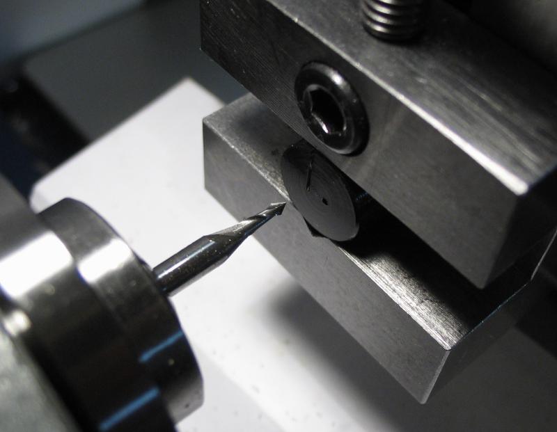
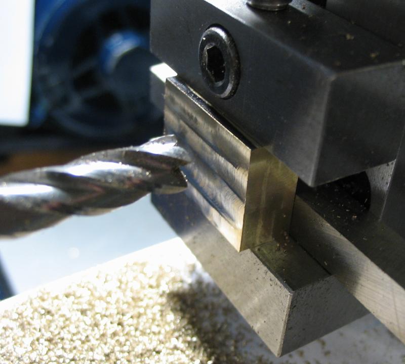
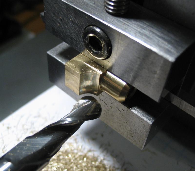
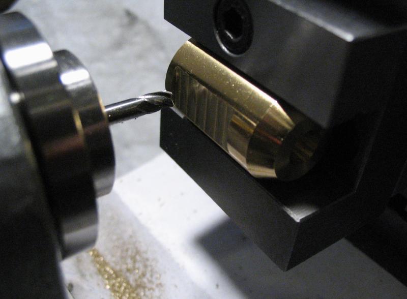
The work was then moved to the machine vise and vertical slide to drill a 0.75mm hole that is 1.25mm off center. This is for the LED cathode leg (0.5mm wire). A channel was milled with a mill-drill bit to a depth of about 0.3mm starting at the anode position (1.25mm off-center and opposite the cathode) and across the face. The work was rotated in the vise to continue the channel down the side of the housing.
|
|
|
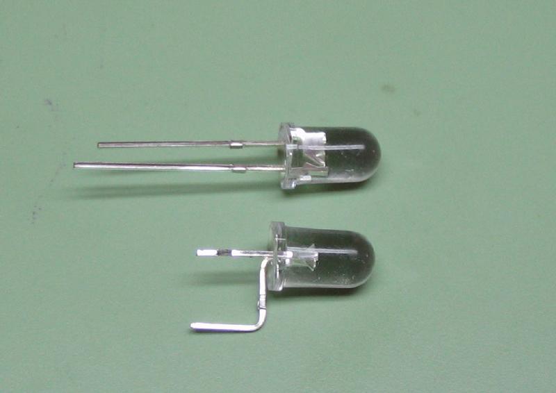
The LED was prepared for fitting to the housing. I chose a 5mm diameter LED that is listed as 16-20,000 mcd (millicandelas) with a viewing angle of 15 degrees. There are seemingly countless options in LED selection, but these were easily available, cheap, and white, bright and had a narrow viewing angle. The cathode was shortened so that about 3mm would be available internally to bend over. The anode was bent to fit in the groove milled in the surface of the housing and needed to be shortened slightly so there is no chance of shorting on the batteries.
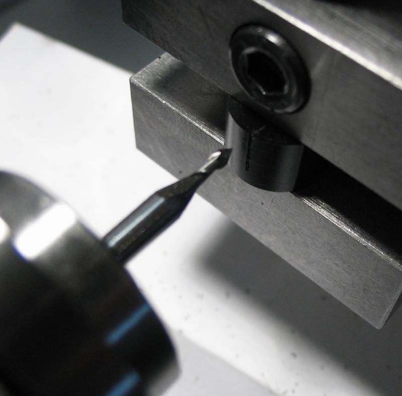
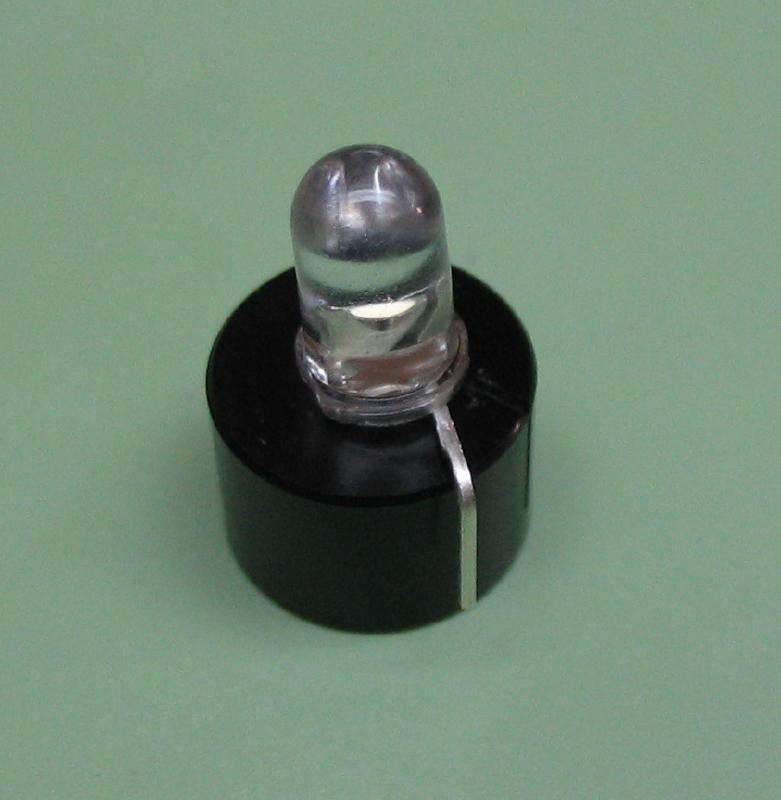
The LED was fit to the housing and the internal leg bent over, which makes things somewhat permanent. The two batteries were stacked and fit into the housing to check their fit. It was an excellent fit, but I then realized removing the batteries is not very user friendly. The work was moved to the lathe again for drilling a 1.05mm access hole for driving the batteries out with a small pin.
|
|

|

|
|
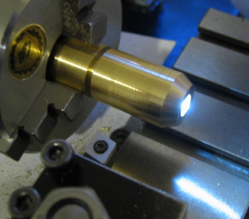
The assembled housing was test fit to the lamp body and pushed into place (the fit was fairly snug). The cap was still chucked on the lathe and lamp screwed on to see if it worked at this stage. The amount of material that will need to be faced off the cap to give a good final fit between the cap and body can ascertained by measuring the gap that remains after screwing down and the LED illuminates.

|

|
The contact face of the cap was turned down to a length that makes contact with the battery surface and is tightened to the desired depth. The diameter is reduced to just over 4mm for 1.4mm length to snugly fit an o-ring (7x4x1.5mm). The o-ring sits just above the contact surface by about 0.1mm. This helps to seal the contact area and also gives a nice feel between the on and off positions.
|

|
The cap was parted off and then screwed onto the lamp body, which was used as an arbor for finishing the cap. The cap was faced true, chamfered, and the milling spindle used to mill six grooves in the cap with a 1/8" ball end mill.
|
|
|
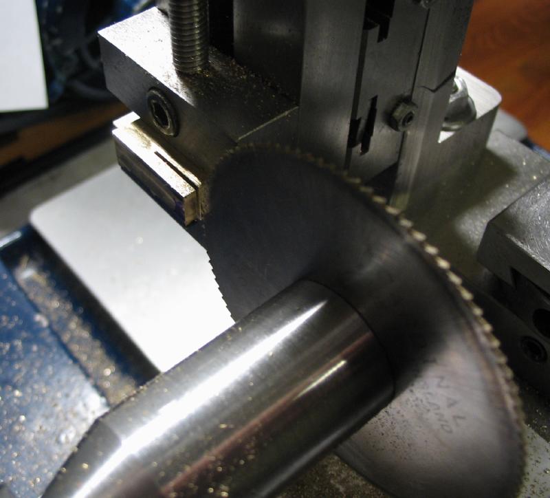
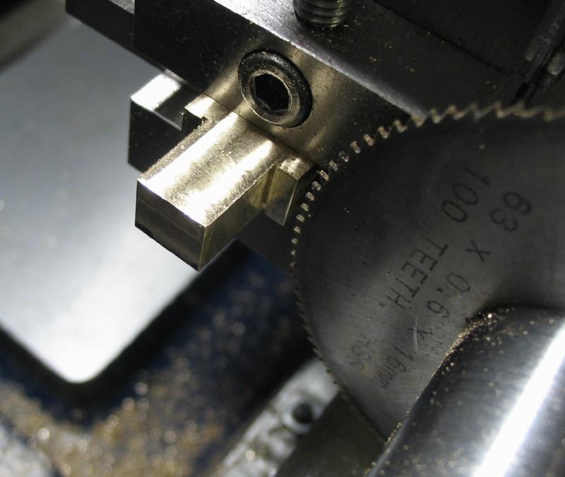
A small bracket was started from a short piece of 3/8" x 1" brass bar. The brass was mounted in the machine vise and face milled on all its sides to true the surfaces and reduce the dimensions to about 15 x 7.5 x 20mm. A slitting saw was used to remove sections on either side to produce a short shank.
|
|
|
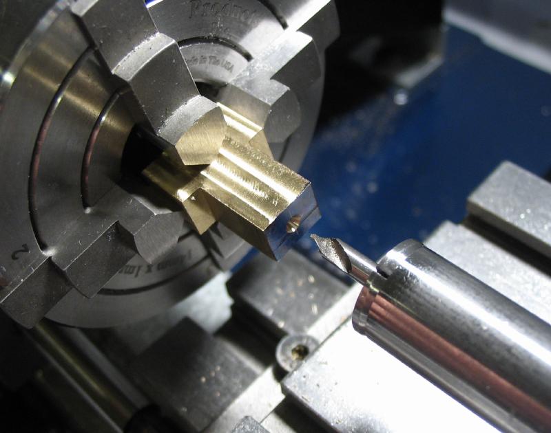
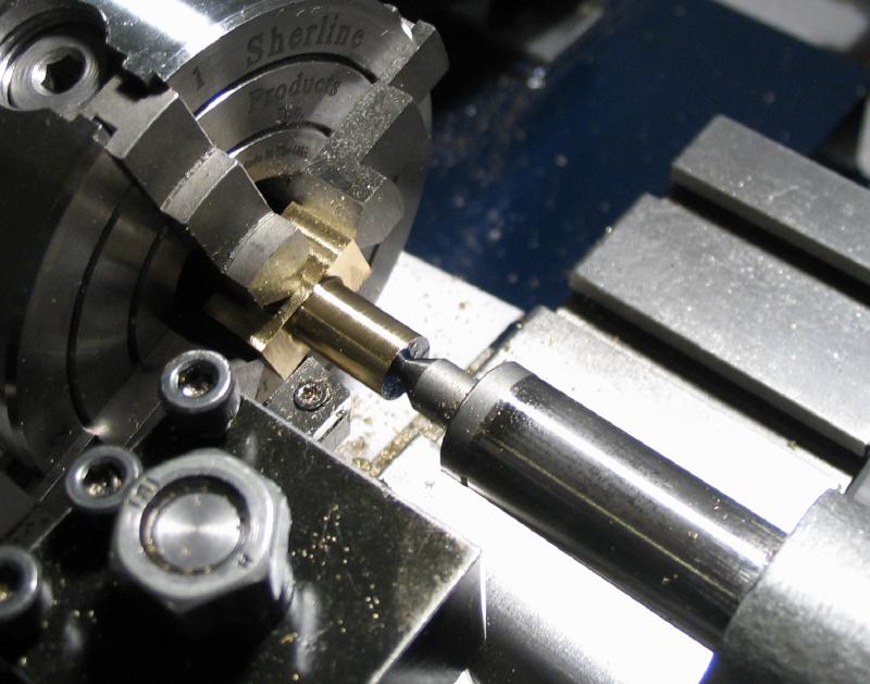
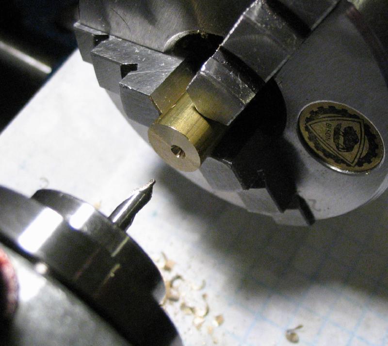
The center was found on the end of the shaft portion, and the work was moved to the 4-jaw chuck to be center drilled. Although fairly short, tailstock support was used while turning the square shank circular and down to 7.5mm diameter. This was then drilled 3.3mm for almost the whole length and tapped M4x0.7. After reconsidering the dimensions, the length was shortened by 5mm by parting off, and the end then chamfered using the compound slide.
|
|
|
|
|
The work was then transferred back to the machine vise, and the corners relieved using half the width of a 7mm ball end mill. Flat portions of the work were given a quick polish to remove tool marks.
|
|
The lamp body was mounted in the vertical slide and milled to provide a landing for the bracket to fit into. The bracket was then permanently attached by soldering. I used Stay Brite® brand of solder, a low melting point alloy of 96% tin and 4% silver. The mating surfaces were fluxed and then simply held in position with the third hand of the soldering station. I obviously used much more solder than was needed, so the joint is quite visible even after filing it down a bit. At least it should stay together!
|
|

|
|
|
|
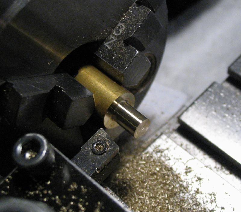
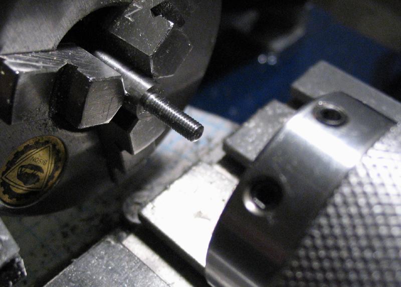
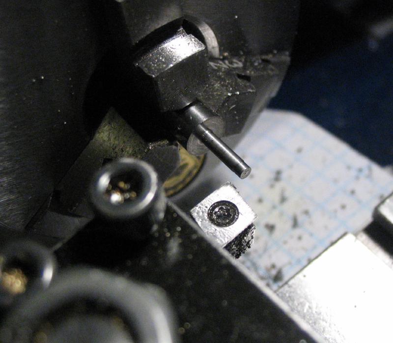
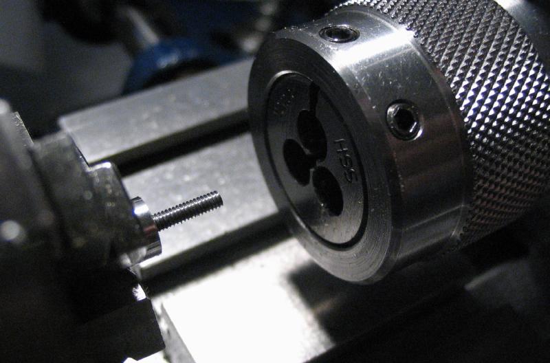
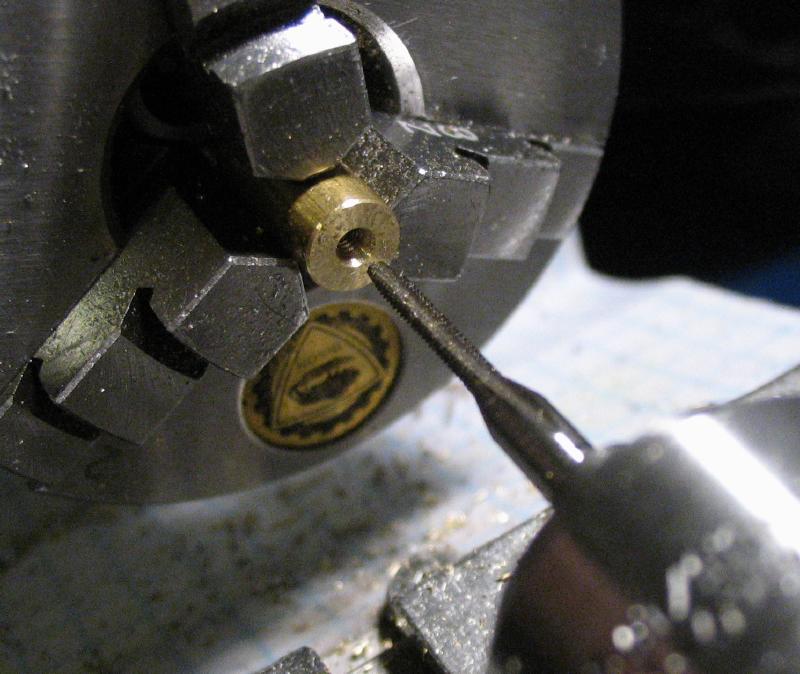
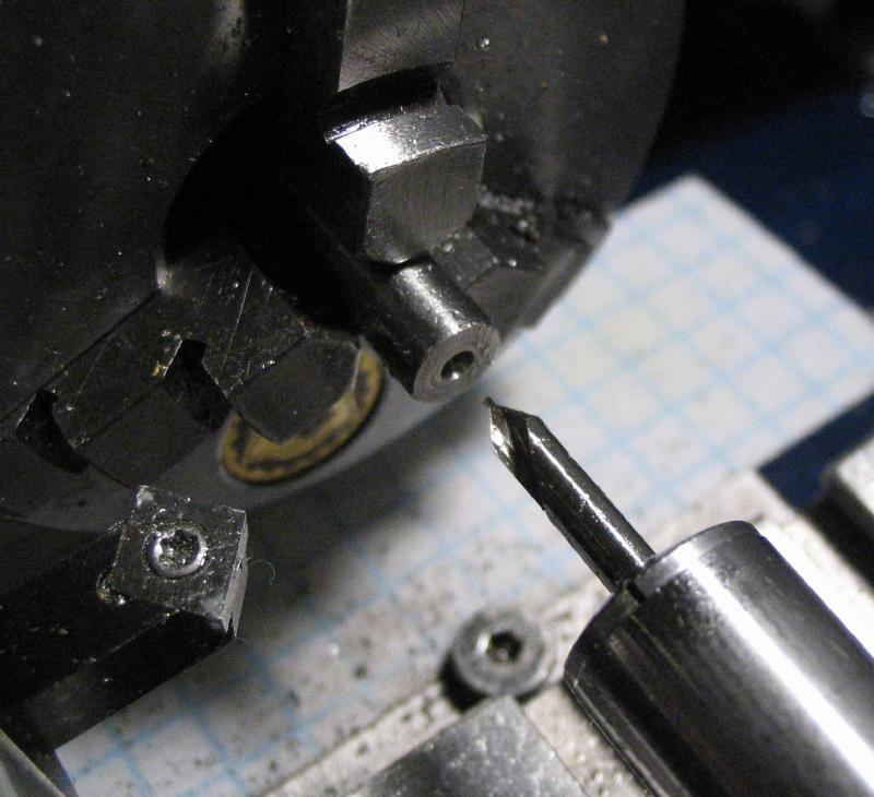
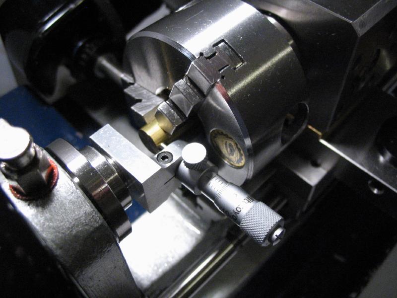
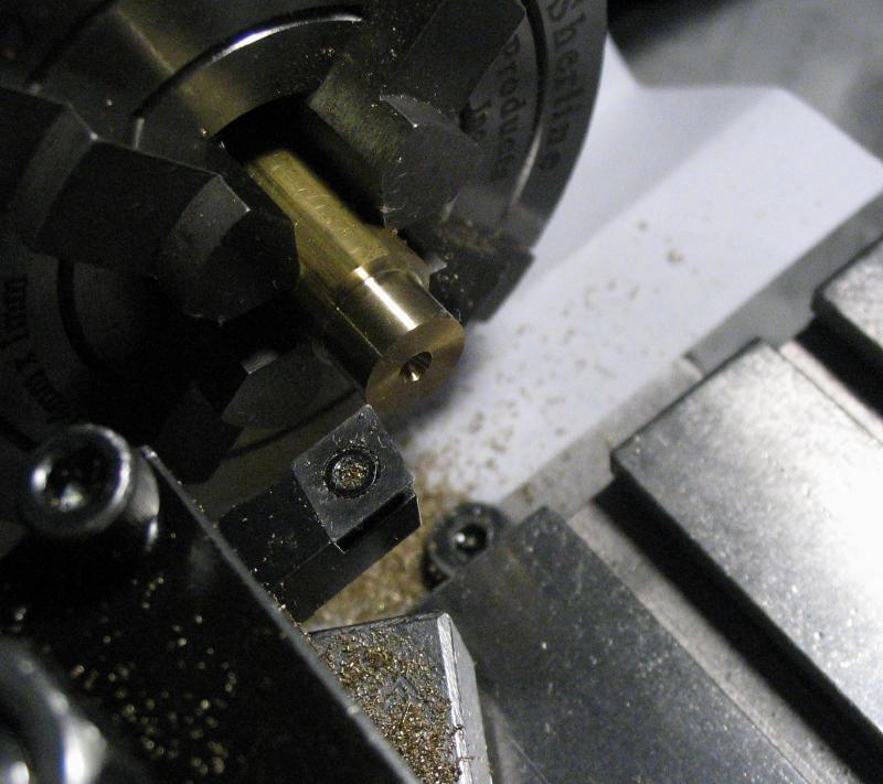
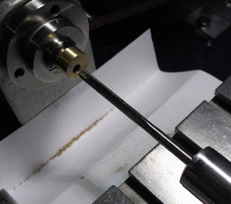
A piece of 5/32" (3.97mm) brass rod was mounted in the 3-jaw chuck and threaded M4x0.7 for a length of about 8mm. This will form the horizontal arm, it will be shortened significantly later on, but a test fit is shown below.
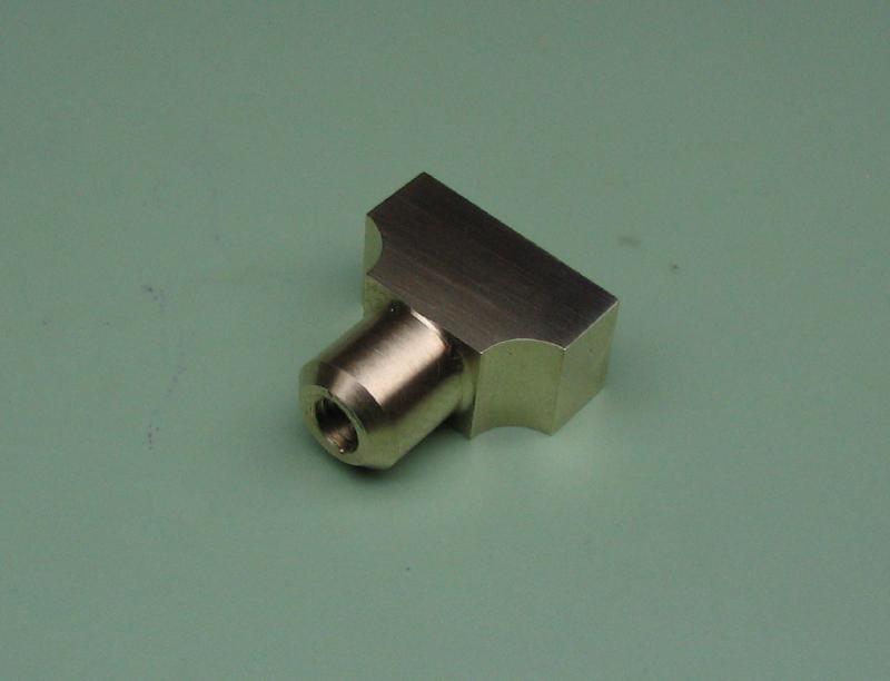
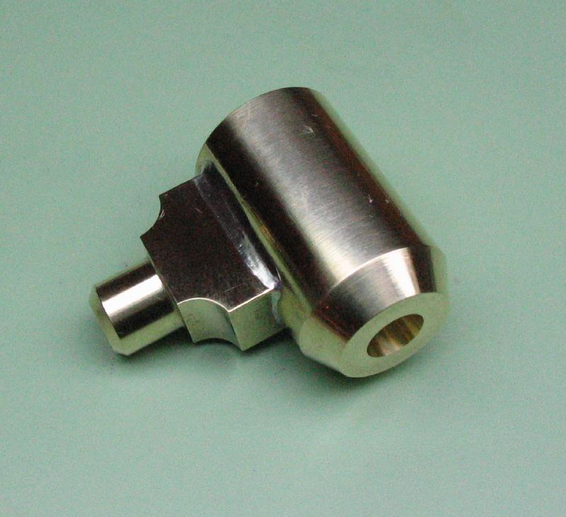
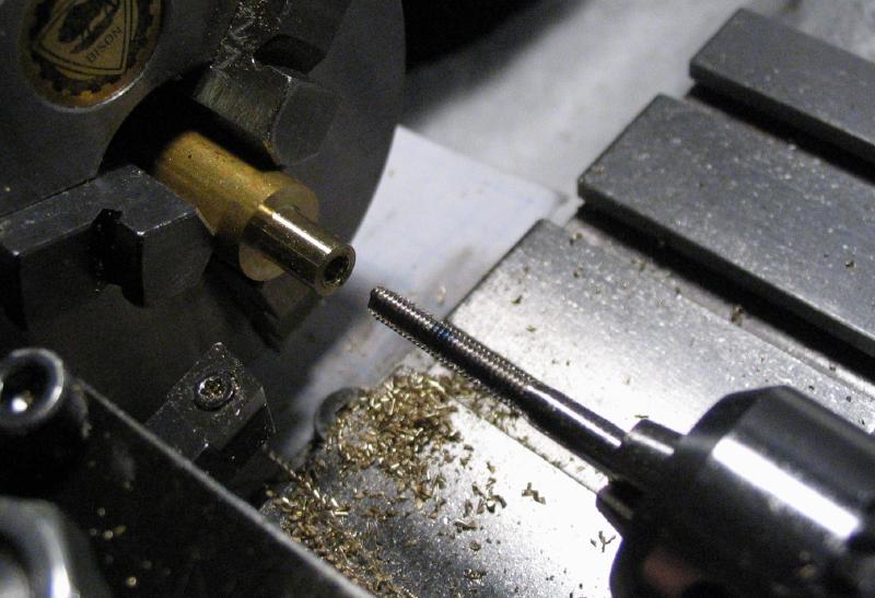
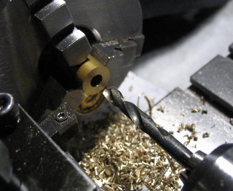
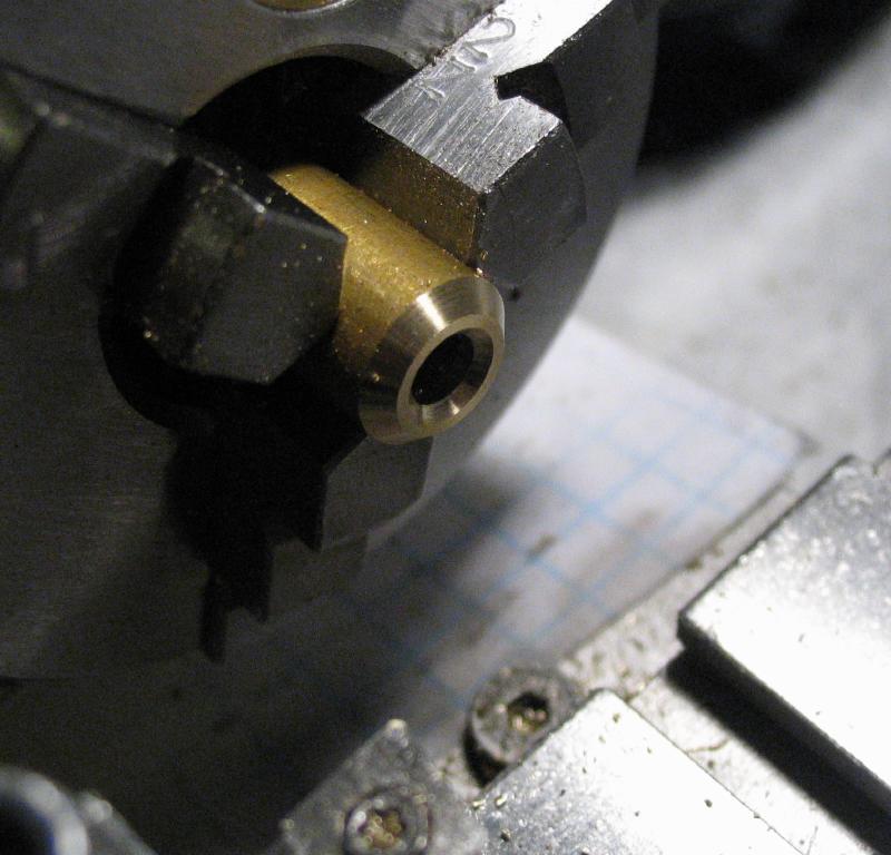
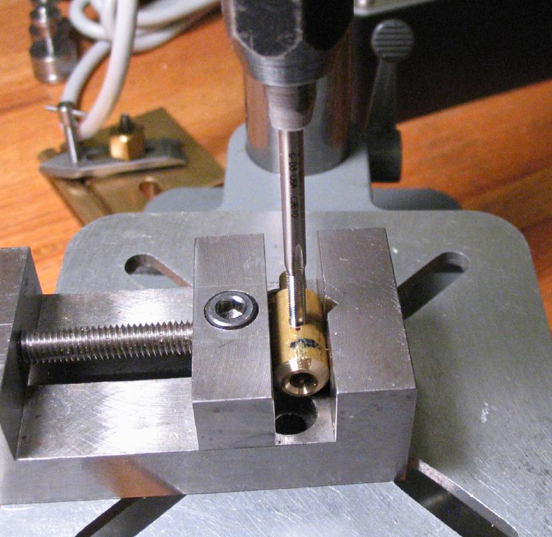
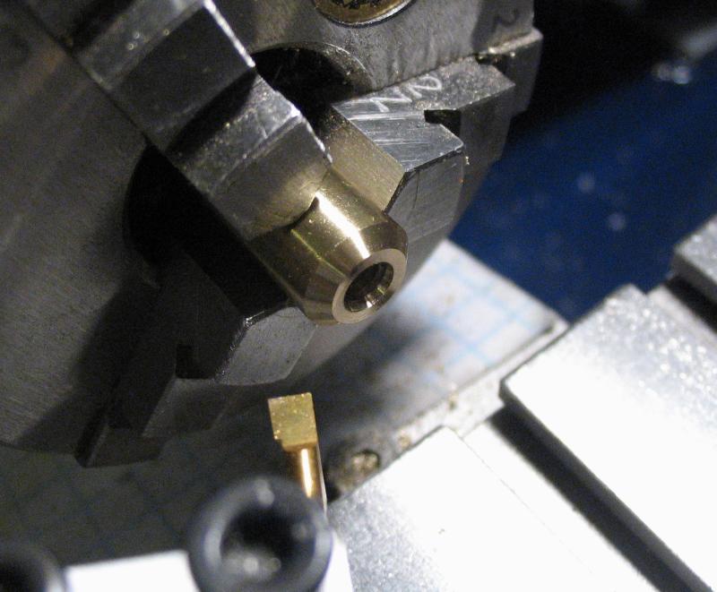
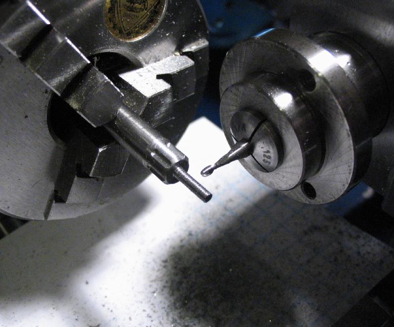
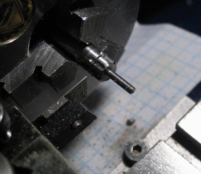
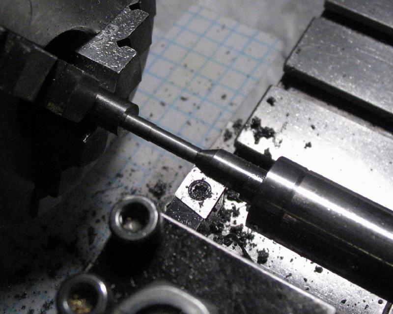
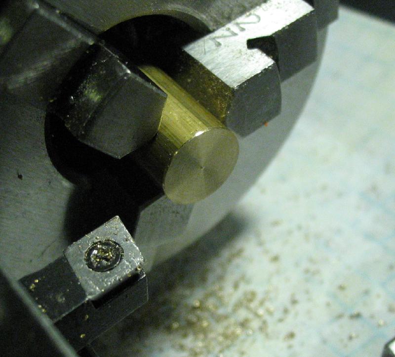
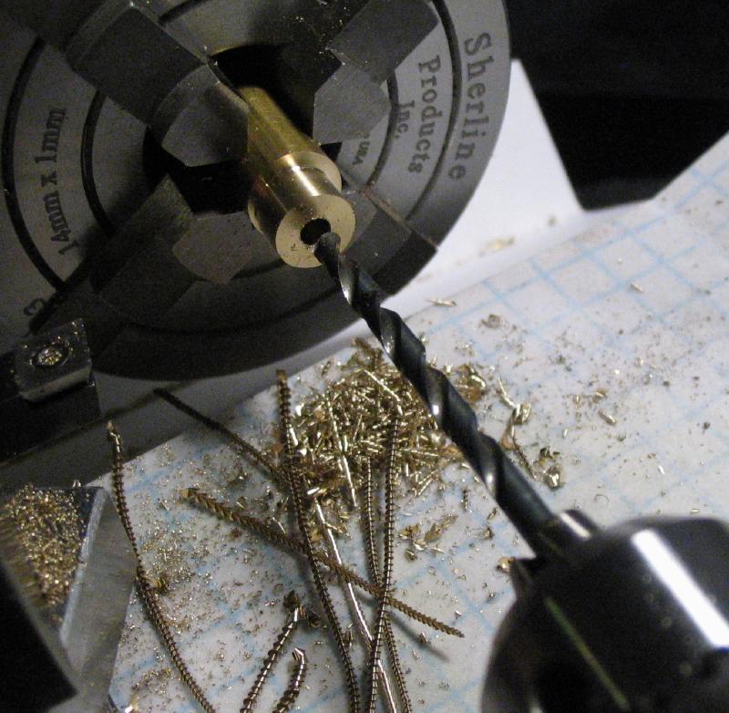
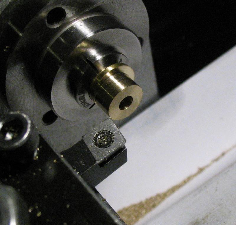
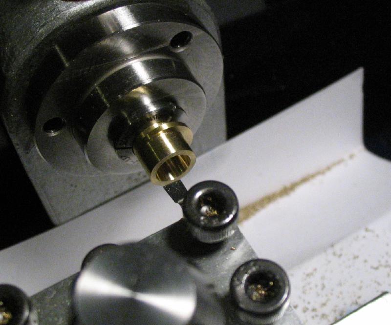
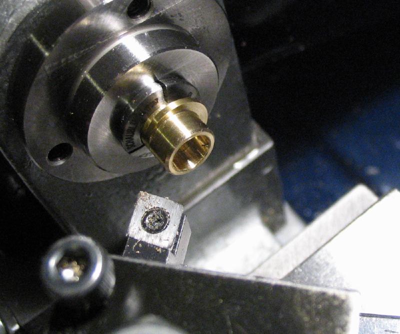
The base for the articulation was made from an inch length of 3/8" brass rod. It was turned down to 5mm for a length of 7mm (about the same dimensions on the base of the tweezer arm from the vintage vibrator above). It was drilled 2.5mm and tapped M3x0.5. The work was reversed and drilled 4mm (the closest I had to 5/32") and chamfered. The work was removed from the chuck and cross drilled 2.5mm and tapped M3 for a set screw that will fix a piece of 5/32" rod. This rod will be the vertical arm.
|
|
|
|
|
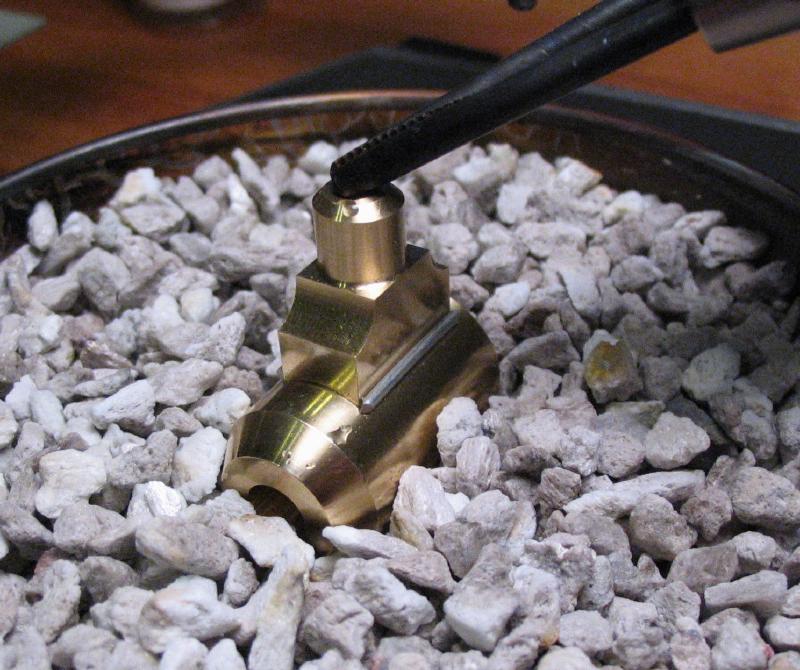
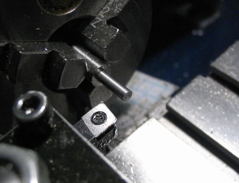
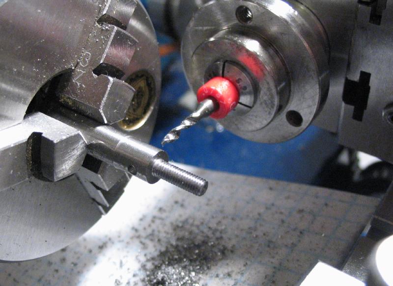
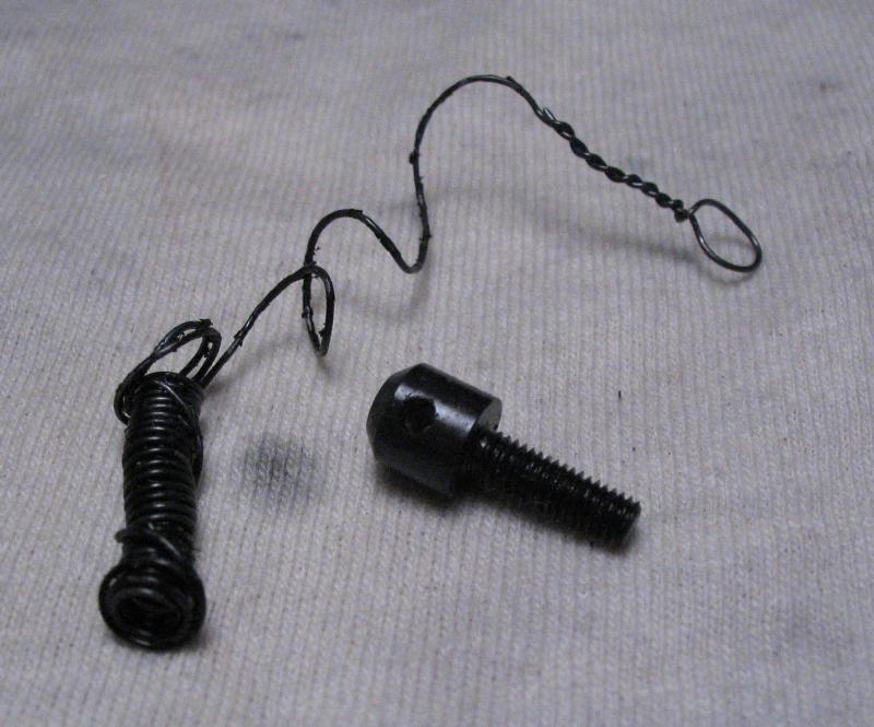
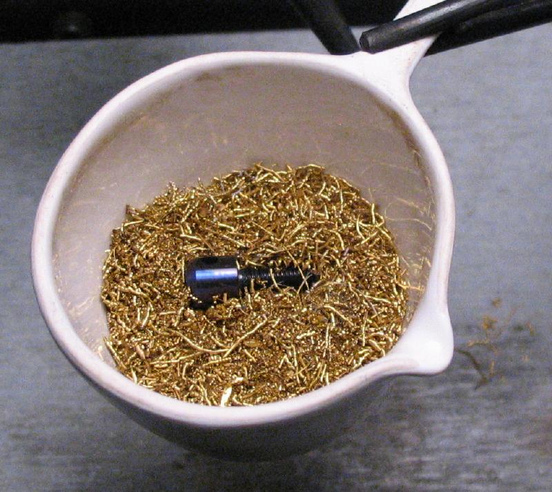
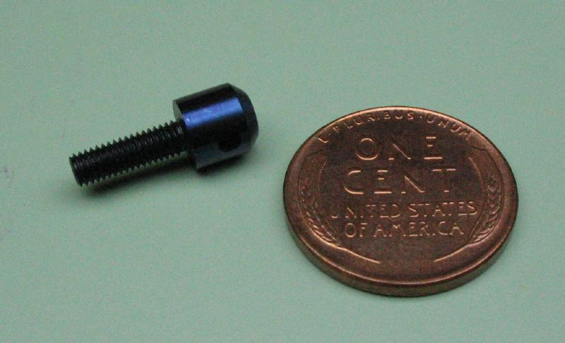
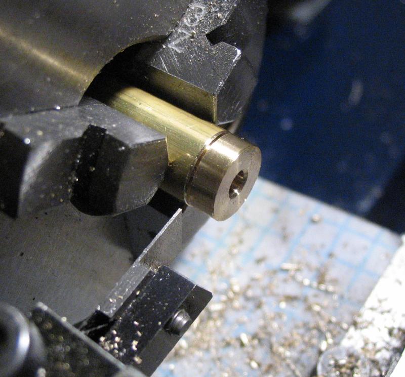
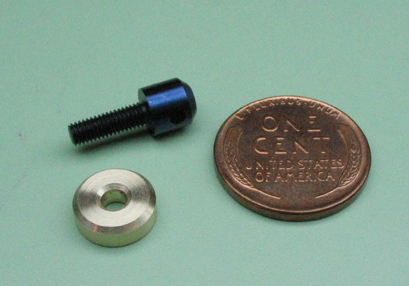
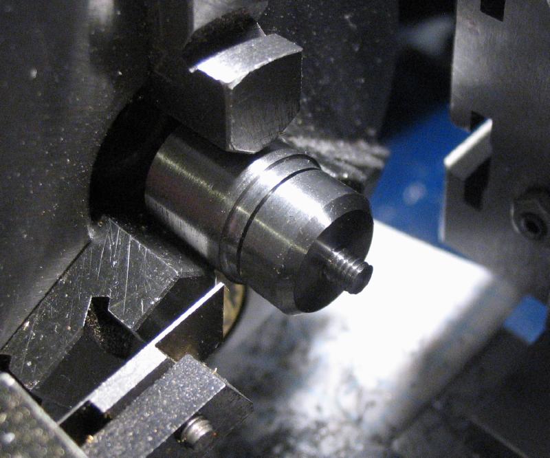
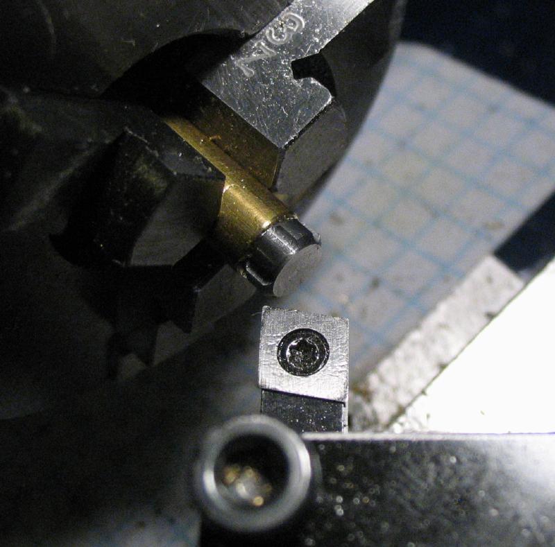
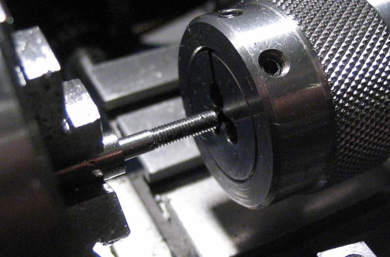
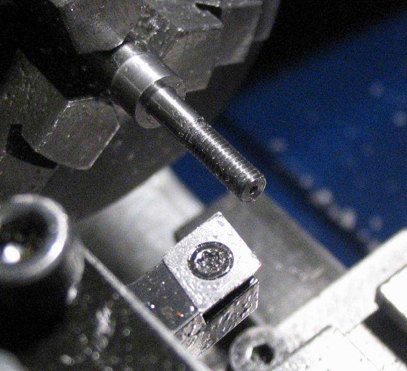
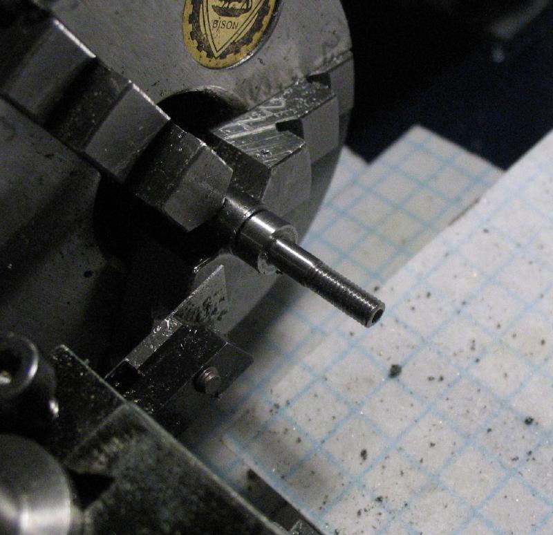
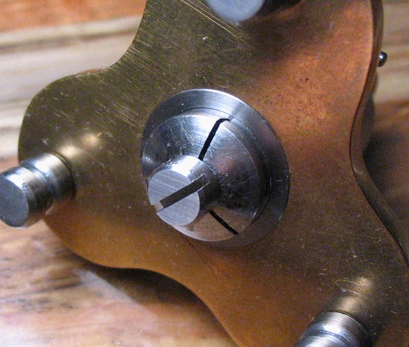
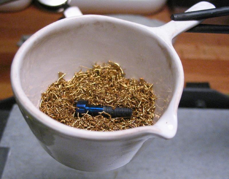
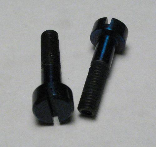
A screw and washer needed to be made to fix this lower mount to the base. It was made from a length of 1/4" oil hardening drill rod. It was turned down to 3mm for a length of 10mm and threaded M3x0.5. It was cross drilled 2mm in the head portion. A regular slot would be awkward to reach with a screwdriver, so the cross drilled hole can be used to tighten/loosen the finished screw. Not shown below, but it was parted off and then reversed in the chuck to face and chamfer the parted end. The screw was hardened by wrapping in iron wire and raising to bright red heat with a small torch and then plunged in mineral oil. It is then polished so that color changes will be visible during tempering. It was heated on a bed of brass swarf in a small crucible so that the heat would be evenly distributed. When it reached a blue color it was removed with tweezers and allowed to cool. It could be polished, but I decided to leave it blue for the time being.
|
|
|
|
|
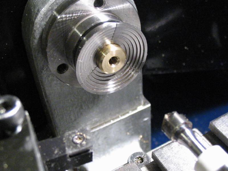
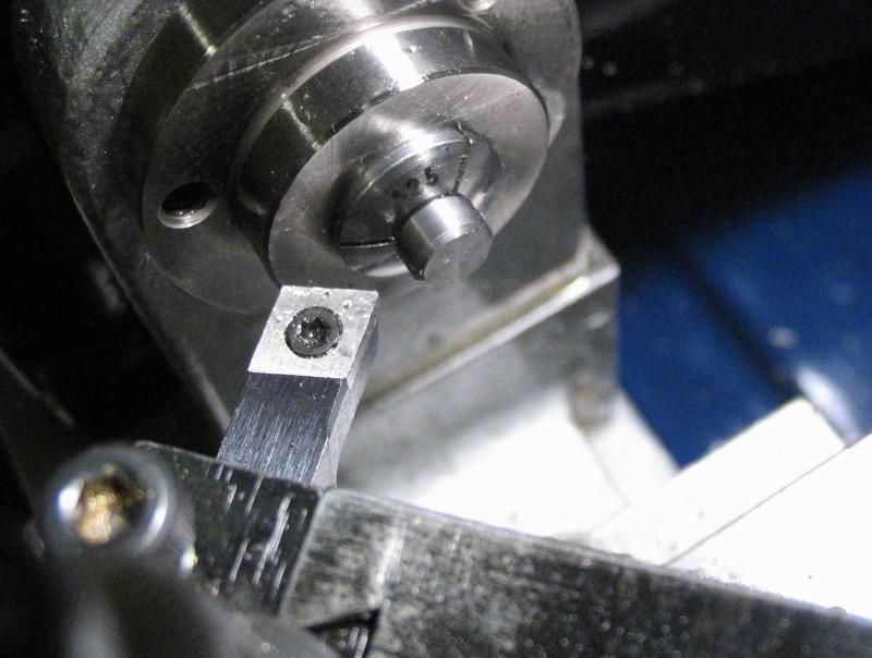
A brass washer to match the screw was made from 3/8" brass rod. It was turned true and drilled 3mm for a short length. A countersink was applied to bevel the opening, and the washer was parted off. It was reversed into a step collet and faced, chamfered, and countersunk.
|
|
|
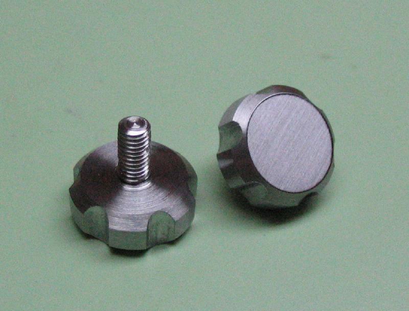
A pair of thumb screws were made from short pieces of 1/2" mild steel (12L14) that were in the scrap box. They were turned down to 3mm for their required lengths and threaded M3x0.5mm. The corner was chamered for about 1mm and then parted off. An arbor was made from 3/8" brass rod, which was faced, drilled ,and tapped M3. The thumb screw was attached, faced and chamfered on the reverse side. The milling spindle was used to mill six grooves to provide a gripping surface. The grooves were formed with a 1/8" ball end mill. They were made from low carbon steel, which is very easy to machine, but they can not be hardened and tempered.
|
|

|
|
Another length of 5/32" brass rod was threaded M4x0.7mm, and will become the vertical arm.
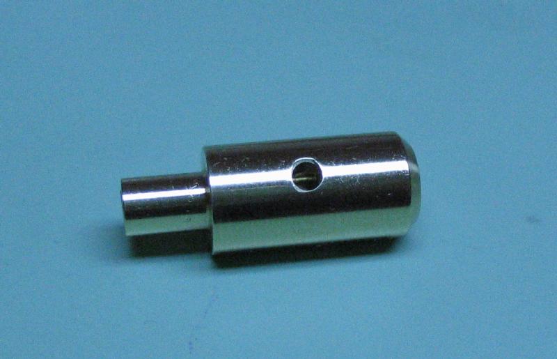
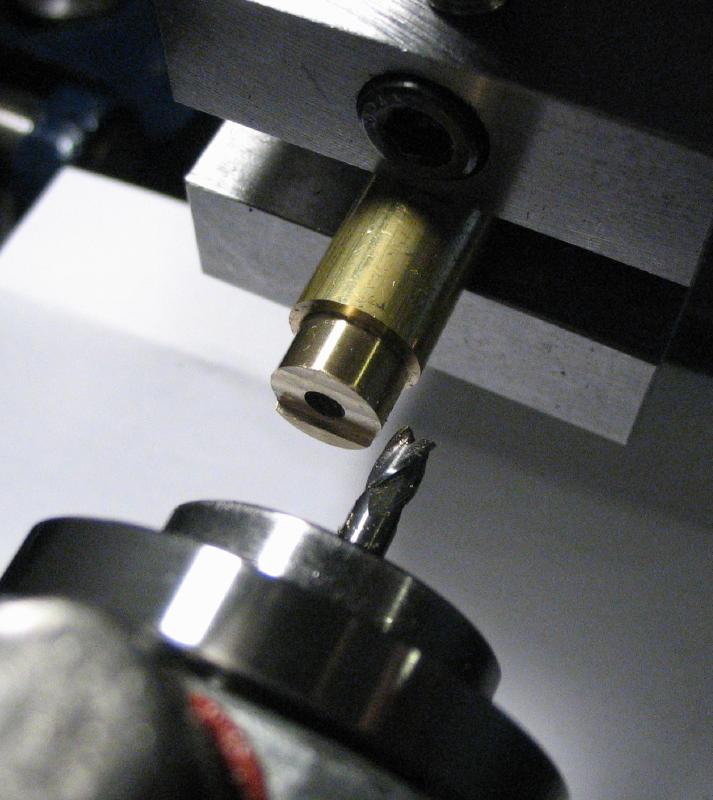
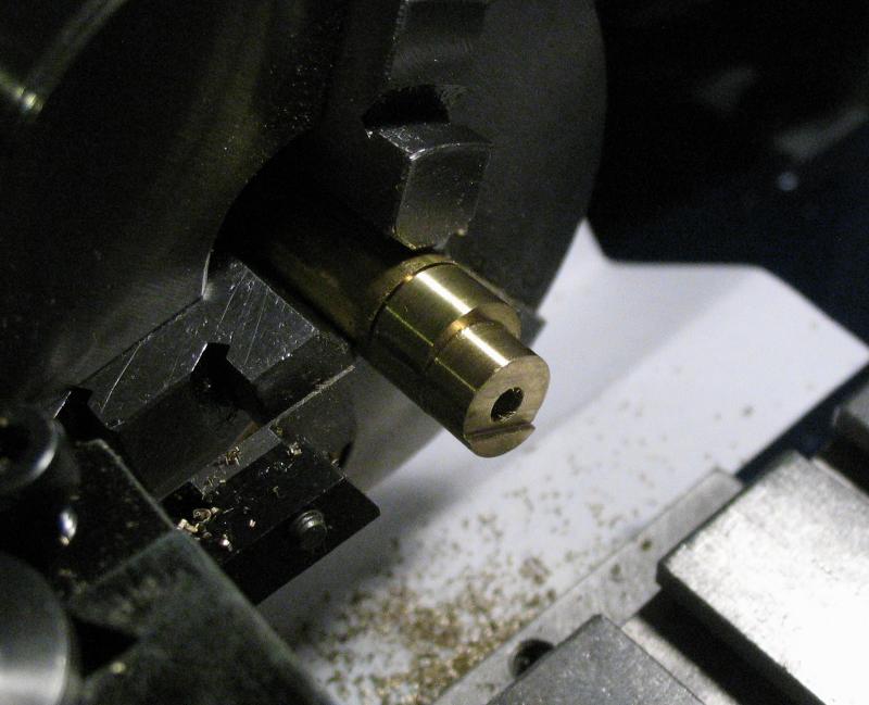
The arbor made above to hold the thumb screws will become the mount for the lamp arm. It was turned true and chamfered, and then cross drilled 4mm to fit the arm. It was then parted off.

|
|
The work was reversed in the chuck, faced, chamfered, drilled 3.3mm, tapped M4, and lightly counterbored just to clean up the appearance.
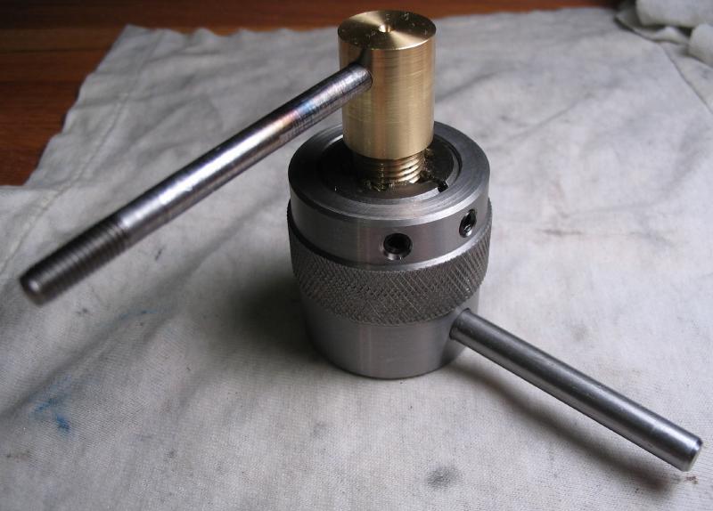
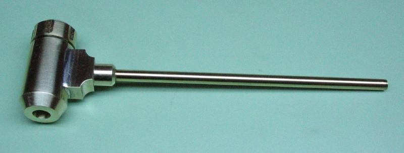
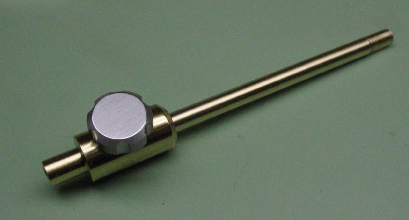
The completed lamp and its adjustable arm is shown. Of course, the correct height and range of arm length still need to be determined so the brass rods can be trimmed to there final lengths.
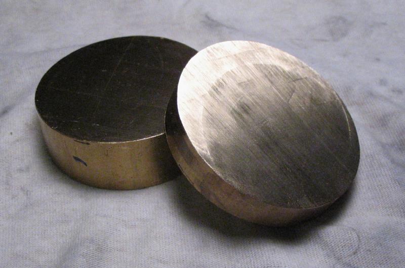
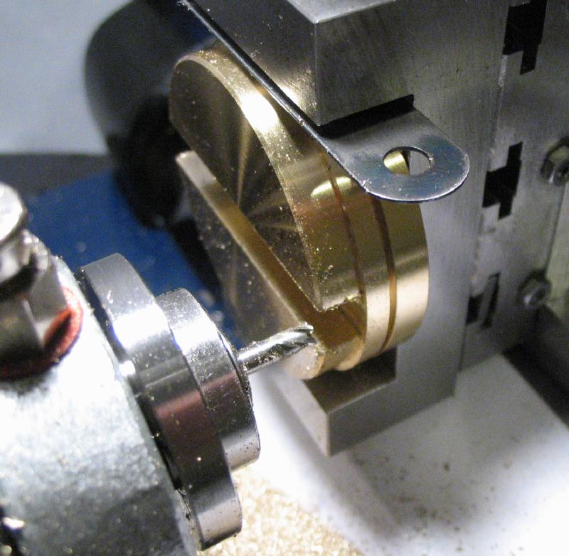
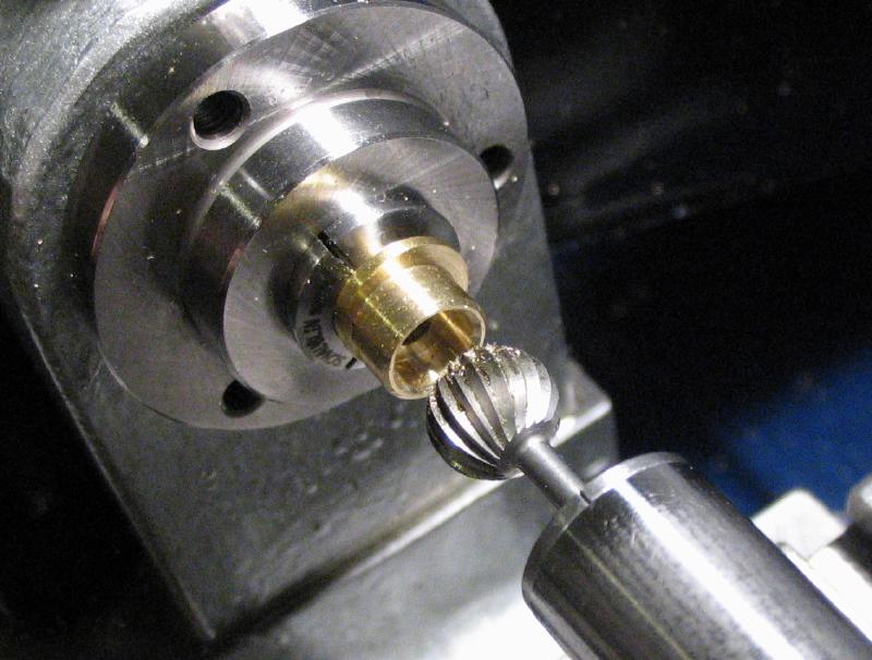
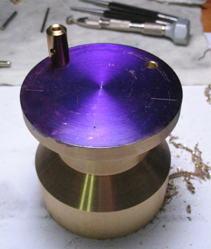
The testing platform is made from two discs of 2 inch diameter brass rod. They were sawed off at about 16 and 9mm lengths. The larger disc will be the base, and was mounted on the lathe for facing both sides and the bottom face recessed for about 1mm and turned down to 50mm in diameter for about 5 or 6mm. The work could be reversed in the chuck and the remainder turned down to 50mm as well. This always leaves a seam where the diameters meet, however, the work was then grooved using a parting tool to provide a location for hold-down clamps. The groove is 1mm wide and 1.5mm deep. The work was also turned down to 48mm for a length of 6mm.
|
|
|

|
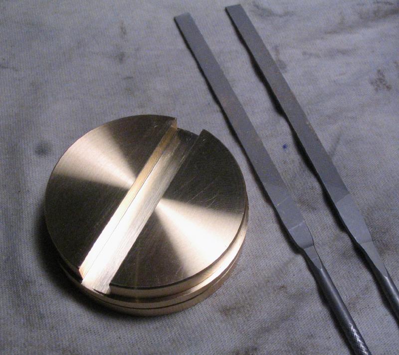
The disc was moved to the machine vise and a slot milled that is 7.5mm wide and down to the 6mm depth of the previous turning step. The base of the channel was smoothed with No.2 and No.4 cut needle files to remove the tool marks. The sides of the channel were left in their somewhat rough finish. This may actually assist in holding the sensor in place.
|
|
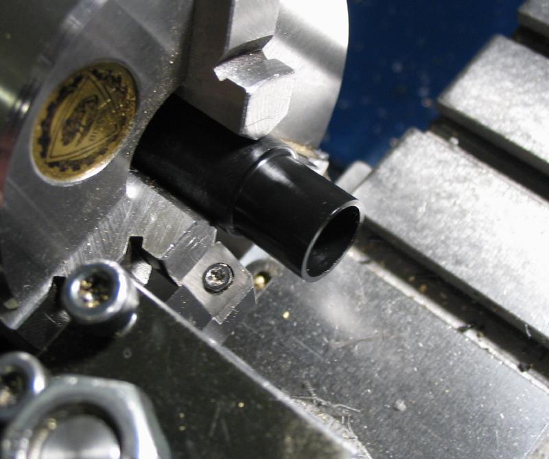
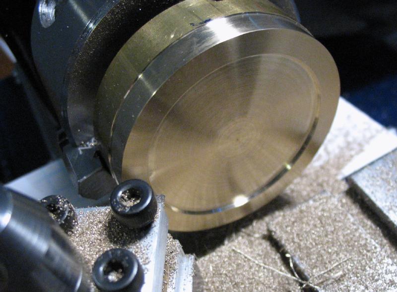
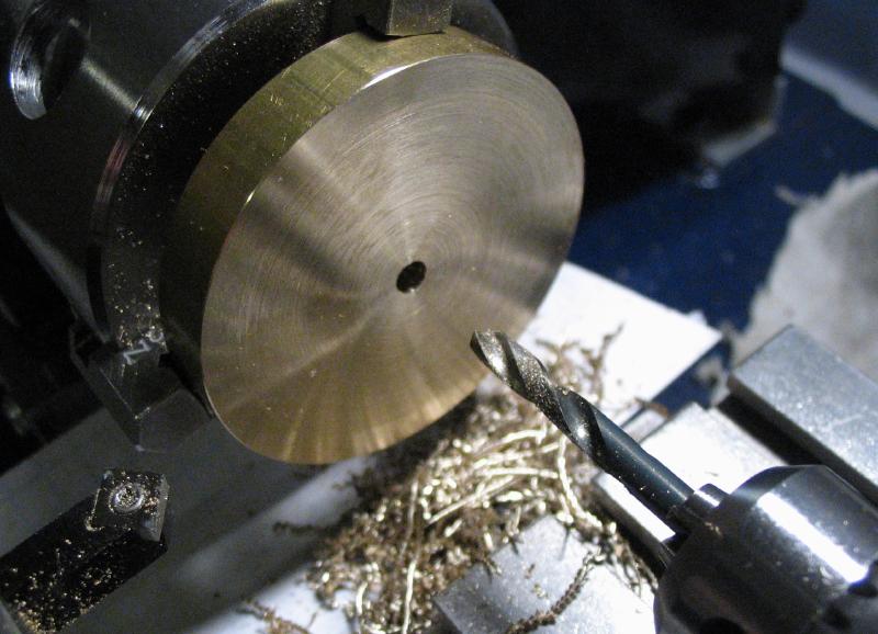
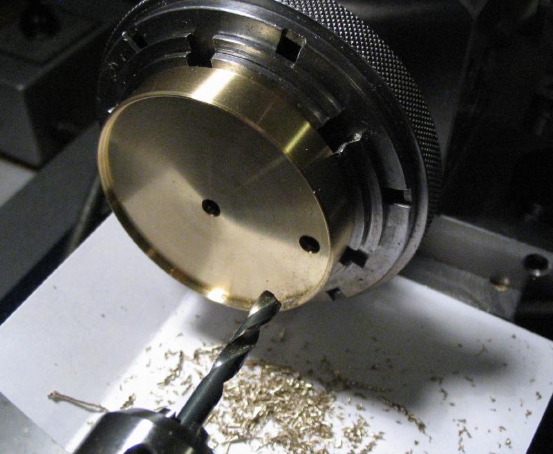
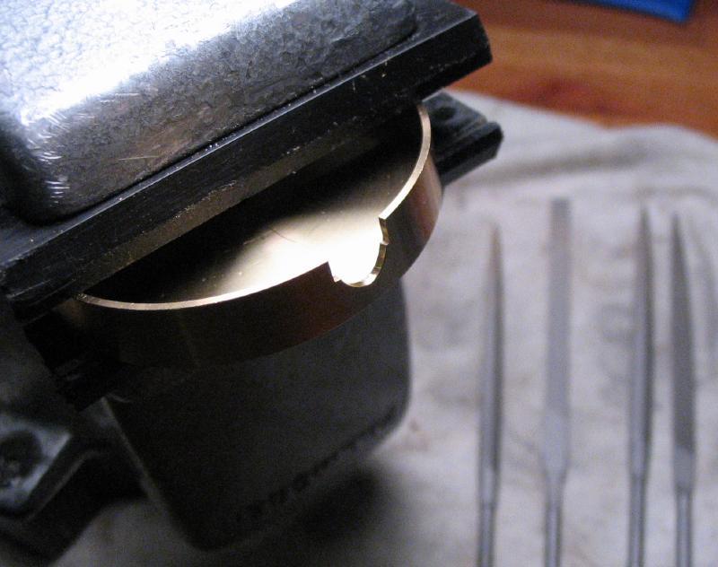
The shorter disc was mounted on the lathe and faced on either side. A viewing slot will ultimately be milled, but it was drilled 4mm for now, which will match the width of the slot. The hole provides a convenient start for the boring bit; I used a Micro100 BB-120250. It was bored open 48mm to a depth of 6mm. This opening will accommodate the top portion of the base made above, so the base serves as a handy test gauge between the final passes with the boring bar.
|
|
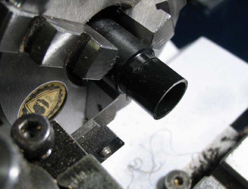
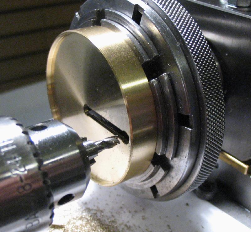
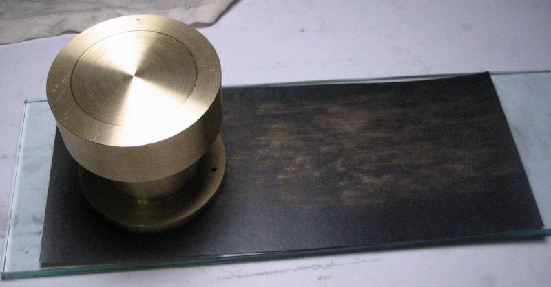
The disc was reversed on the chuck and held internally by the bored surface. The top face was also bored open to 48mm, however, this is to fit a piece of round and flat glass (48mmx1mm thick). It was bored to a depth of about 1.4mm to give a small amount of excess that was chamfered. The outside diameter was turned down to 50mm to match the base portion.
|
|
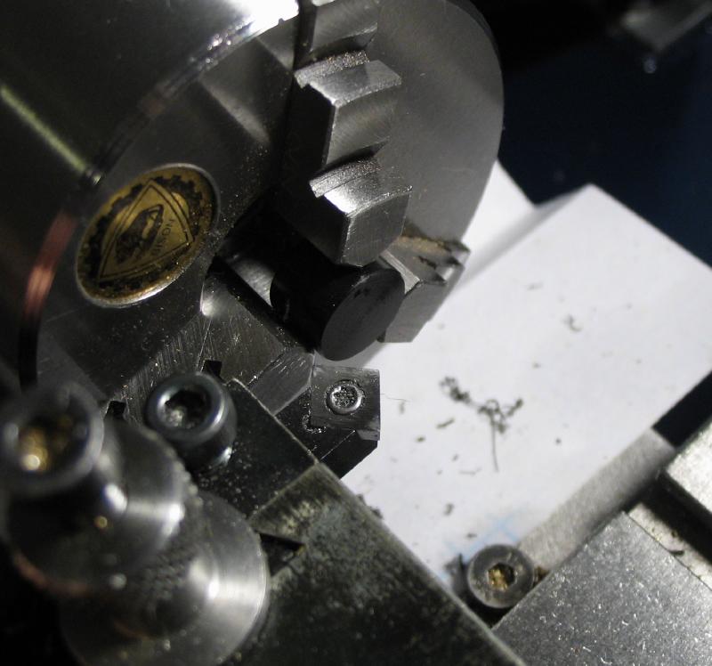
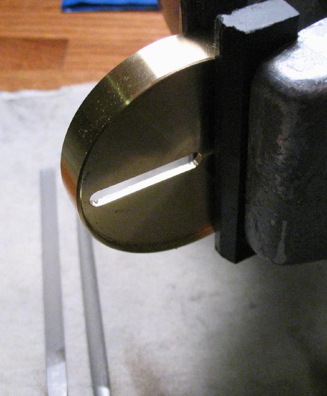
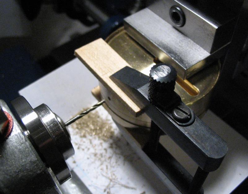
The disc was transferred to a 6-jaw bezel chuck and the chuck mounted in the dividing head, which was set on center height on the cross slide. Another 4mm hole was drilled closer to the edge, and the two holes joined by milling a slot with an endmill. I did not have a 4mm endmill on hand, so the edges needed to be finished by filing. The work could have been mounted on the vertical slide in order to widen the slot by milling, but it will need to be finished with a file anyway.
|
|
|
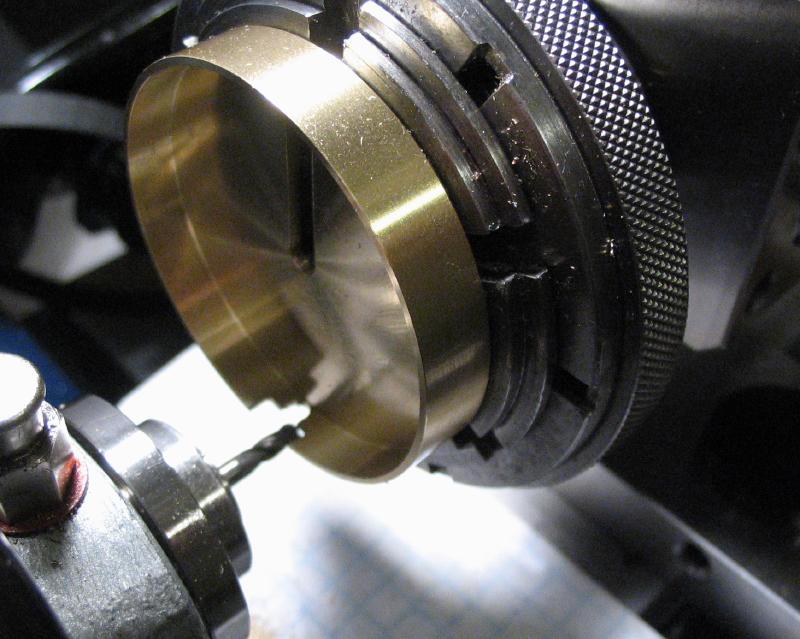
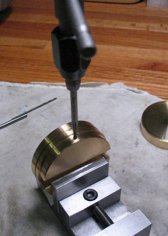
The disc was reversed on the chuck and the dividing head moved to the vertical slide. A notch was milled out that is in alignment with the channel of the lower portion of the platform. It could have been milled open to a full 7.5x6mm to match the channel, but I attempted to shape the opening to better match the profile contours of the sensor, which is not easily machined and required some finishing with files.
|
|

|
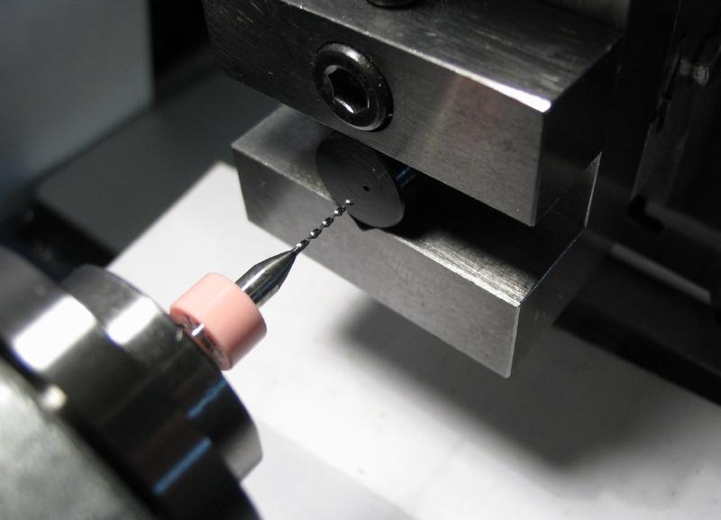
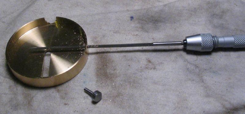
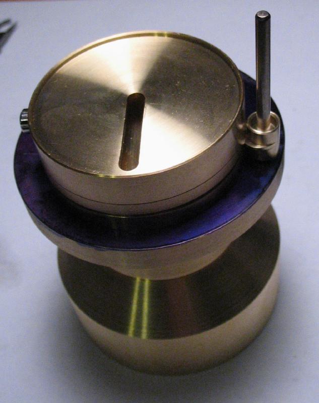
The two halves of the platform fit together fairly well, it takes some twisting to free them apart. However, this may change over time and I decided to add a fixing screw. The platform was assembled and the slot and opening aligned. They were fixed into position with a toolmakers clamp and a couple strips of wood as clamping pads. The assembly was moved to the machine vise and drilled 1.6mm for a generous depth (about half an inch). They were separated and the hole in the lower portion tapped M2x0.4.
|
|
The hole in the upper portion was broached open to pass the screw made below.
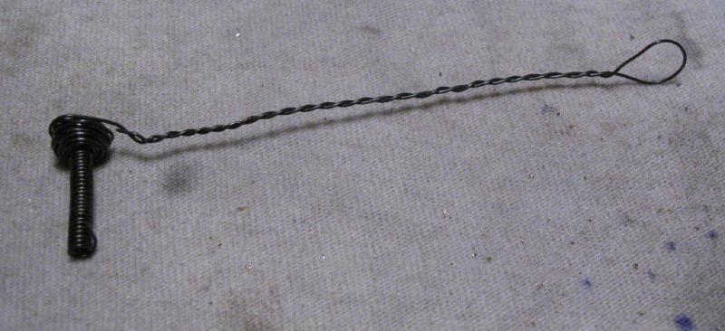
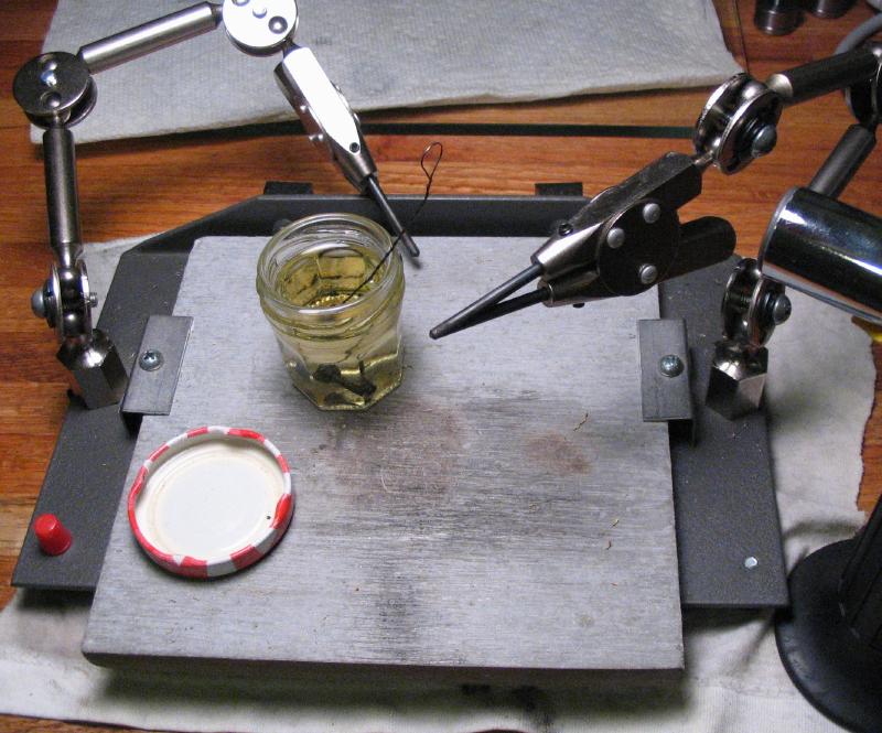
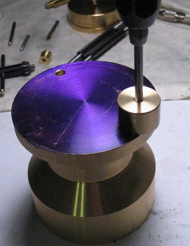
The steps for making the fixing screw are shown below. I spent the better part of a Saturday afternoon making this screw, but just about any stock M2 screw would do here. It was made from 1/4" oil hardening drill rod, turned to 2mm for about 8mm. It was threaded using a die, and the head of the screw turned true and to about 6mm diameter for about 1/4" length. The milling spindle was used with a 1/16" ball end mill to form 6 grooves that will be the grip for the finished screw. The corner was chamfered 45 degrees and the work parted off. An arbor was made from a short piece of 1/4" brass rod, faced, drilled, and tapped to fit the screw. The top face of the screw could then be faced and chamfered. The screw was wrapped in iron wire and heated with a small torch to bright red and plunged in a small jar of oil. The third-hand of the soldering station works as a steady while heating and rotating by hand, and keeps it close to the oil. It was polished up and buried in a bed of brass chips and slowly heated to a purple-blue temper and finally repolished.
|
|
|
|

|
|
|
|
|
|

|
|
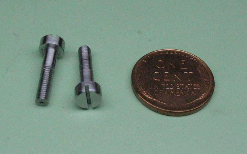
While on the subject of making screws, a pair of screws are needed for the clamps to secure the testing platform to the base. The heads are slotted for use with a regular screwdriver. They were turned from 1/4" oil hardening drill rod and given a plain shoulder of 1/8" diameter and M3x0.5 threads that will fit the base. Tailstock center support was used, and after parting off, the heads were slotted with a 0.032" jewelers saw while held in the dividing head on the vertical slide.
|
|
|
|
|
|

|
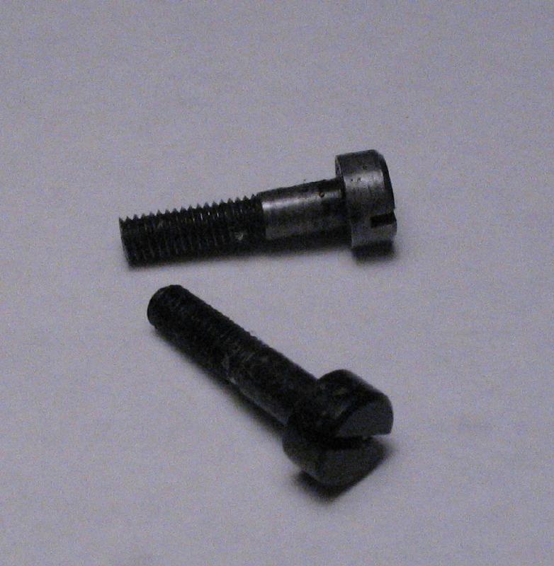
The screw heads were flattened using the screw polishing jig and several grades of emery paper ending with 800 grit. They were hardened, polished, and tempered to a blue color. They could then be given a final polish.

|
|
|
|
|
|
A pair of clamps were made from 3/8" brass rod. A length was faced on either side and the chuck moved to the cross slide to center drill a position that is 4mm from the edge. The rod was then setup in the 4-jaw chuck and adjusted to bring on center. A 5mm length was turned down to 8mm and drilled 2.9mm.
|
|
|
|
|
The work was reversed into the machine vise and the bottom face milled to leave a step on the side opposite the flange. It was then returned to the 3-jaw chuck, and parted off. The work was reversed into a 8mm collet and the center caught with a 1/8" reamer. After reaming, the top face was turned true and then a matching length turned to 8mm diameter. The flange was left at about 0.9mm thickness.
|
|
|
|
The bore for the screw was opened to 6mm for a depth of 3mm to fit the screw head. The edges were chamfered by turning or with a ball end bur.
|
|
|
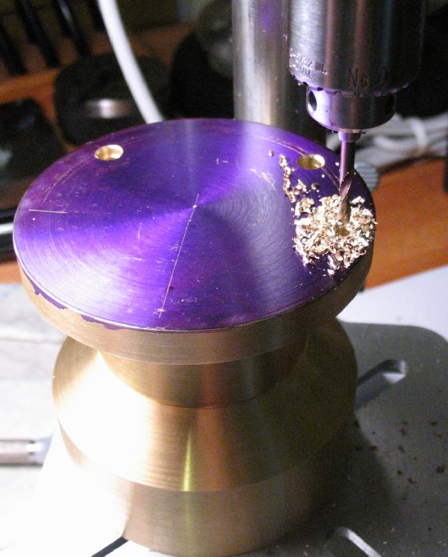
The base was drilled 5mm for the tweezer arm and the lamp arm base. The hole was reamed 5mm and lightly countersunk by hand to give a good fit. The process was repeated on the opposite side

|
|
|
|
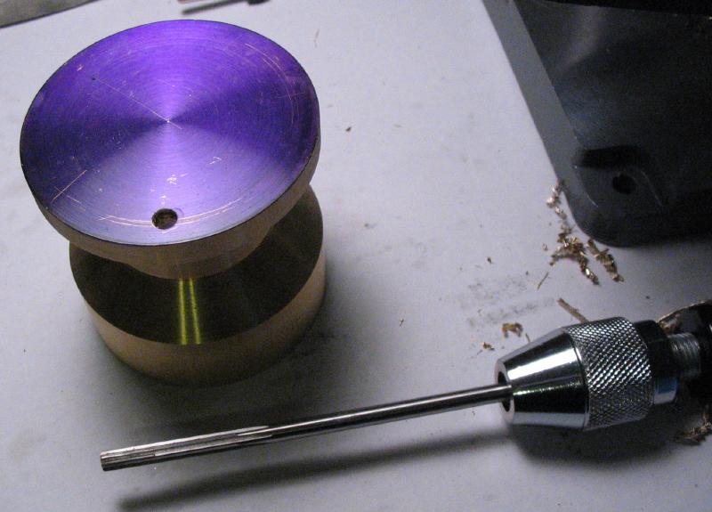
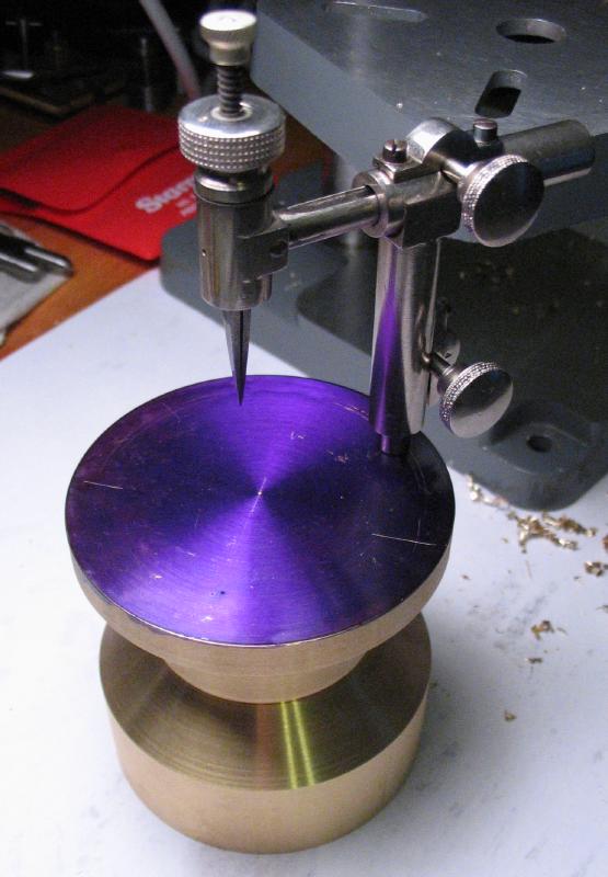
A piece of 1/8" drill rod was turned with a 60 degree tapered point and hardened and tempered. It can be used to scribe the location for the clamps on the base. The position was found with a prick punch, center punched, drilled 2.5mm, and tapped M3x0.5 using a small guide to help get the tap started upright. The guide is a short piece of brass rod faced on either side and drilled and reamed 3mm. Once the first clamp is installed, the second clamp's location can be ascertained and the process repeated.
|
|
|
|
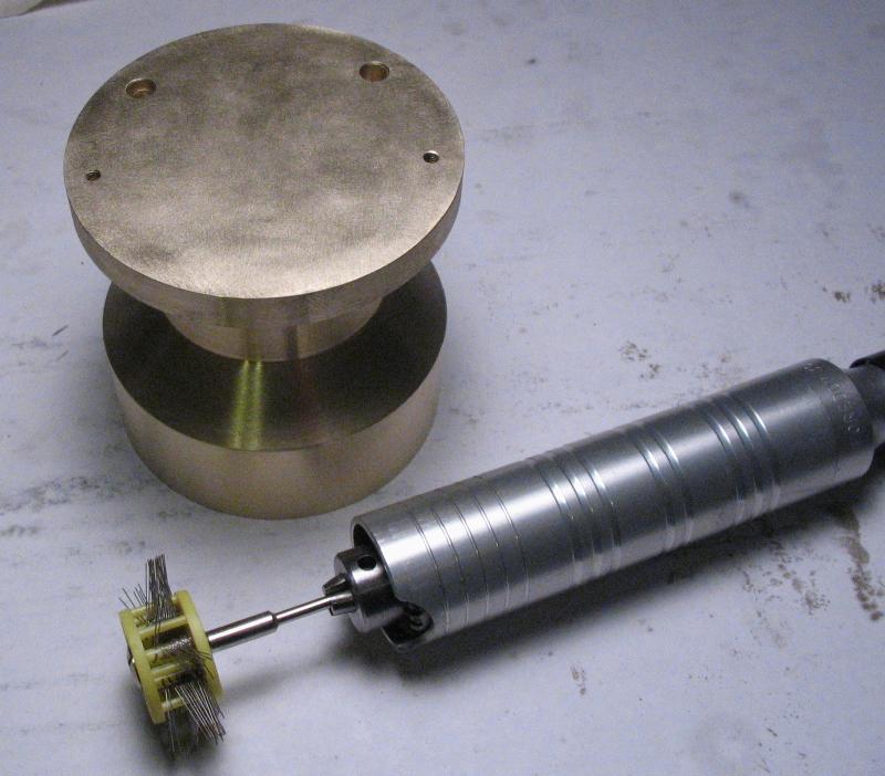
The layout blue was removed with alcohol, and the base generally polished up with 800 grit emery paper. The top surface was given a frosted finish with a wire brush.
|
|
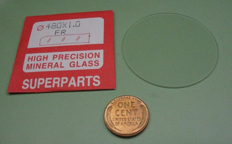
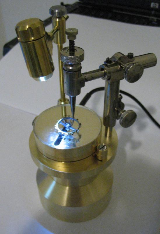
Everything was given a good cleaning and assembled. The range of the lamp arm that is usable was determined and the arm sawed off and finished off with a cup bur. A stock 48 mm diameter x 1mm thick flat mineral glass was installed in the testing platform cover. It is now ready for testing!
|

|

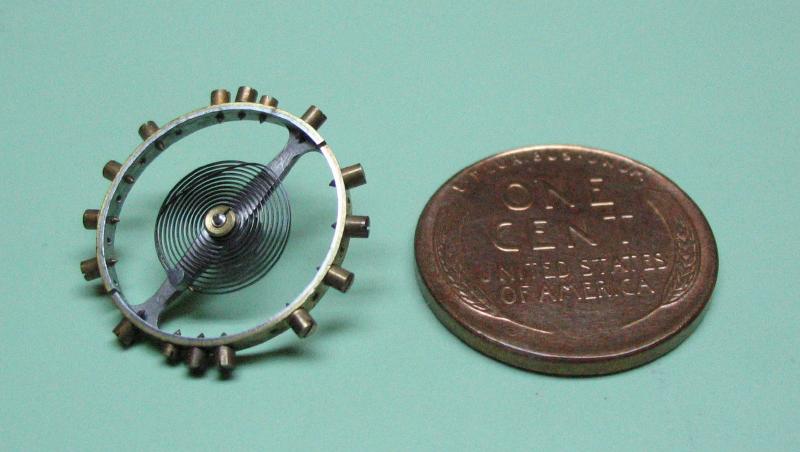
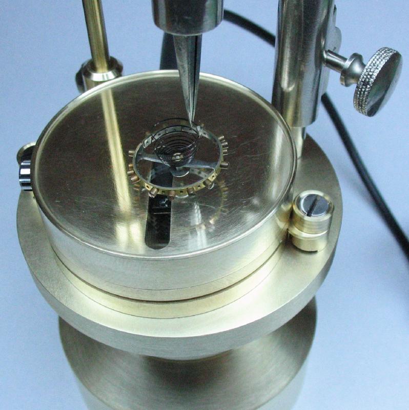
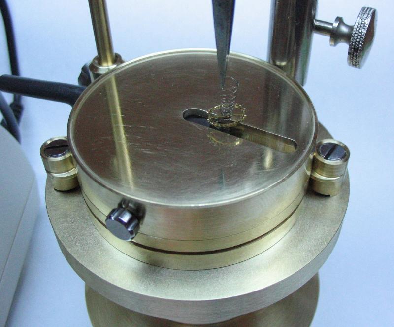
To see if this whole arrangement actually works, an orphaned 18S Elgin balance wheel with its overcoiled hairspring and collet still intact was tried. The staff still has the roller attached, although the roller stone is missing, and the upper pivot of the staff is broken, but this should not have much influence on the experiment. The hairspring gripped by one of its outer coils using a pair of No 5 tweezers and transferred to the pincers of the vibrator setup. The adjustable height of the pincer was used to lower the balance so that the lower balance pivot is just touching the glass. An arm of the balance is placed over the sensor by one of the variety of adjustments : the arm length of the rotating pincer, the sensor can be moved in or out of the platform, or the platform itself can be rotated.
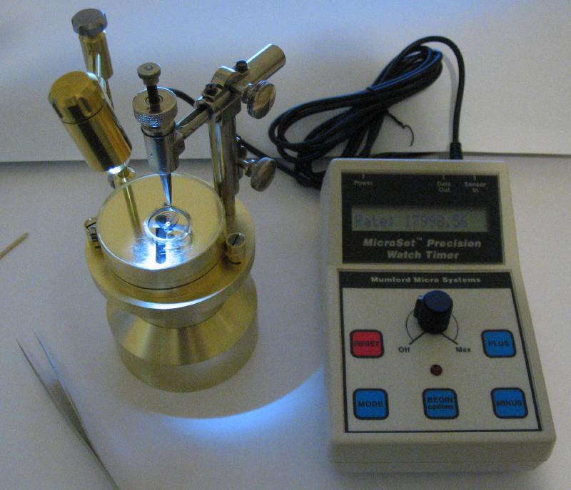
The LED lamp is turned on and the thumb screws on its arm slackened to allow the lamp to be positioned so that a shadow of the passing balance arm will be cast over the sensor. The Microset is turned on and prepared for assessing a rate of 18,000 beats per hour (bph). The Microset can be programmed to determine the average of a set number of beats. The default is 10 and this seems to work fairly well for this application as well. The balance is set oscillating by hand using a piece of peg wood to rotate the balance and by arresting it with thumb and forefinger, it is flexed about 300 degrees and released. The Microset is started and the gain knob is increased until the red LED indicator begins blinking (at about the same rate as the passing balance arm). The balance will continue to oscillate at a readable amplitude for at least a minute or more, and gives plenty of time to make many measurements. The Microset displays the calculated rate after every 10 triggerings of the sensor. Much to my surprise, the whole setup worked quite well on the very first try; I thought I would at least need to adjust the height of the lamp, but it seemed to work well as is. The readings were fairly steady with reasonable deviation, of course the balance is continually loosing energy, but there did not appear to be any false readings or error with the sensor.

|
|
|
|
|
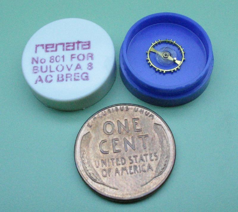
Just to see if it will work with a smaller sized balance, I tried an old stock replacement balance for a Bulova 8AC that is the smallest balance in my collection of miscellaneous parts. The small size makes it rather tricky to work with, but after getting it mounted and making a few adjustments to the position of the sensor and the lamp, I was able to get fairly steady rate readings. However, I would not look forward to actually trying to fit a spring to such a small balance.
|
|
