Piloted Counterbores
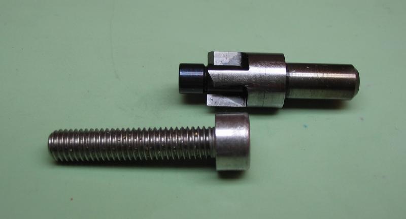
To bore the recess for a screwhead, a piloted counterbore is a useful tool. They can be purchased in standard screw sizes, and the only ones available in small 'watch sizes' are offered by Bergeon and are frightfully expensive. Making an equivalent type of tool, special for the purpose, is relatively simple. The first one described on this page was made while working on the set of 'turns'. A locking screw with a 6mm head, 1/8" shoulder diameter, and 3mm threads was made. A counterbore with a 1/8" pilot and 6mm cutter was needed. Obviously, no commercially made tool would be available, and these dimensions were simply a matter of convenience.
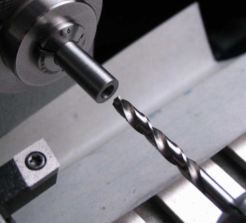

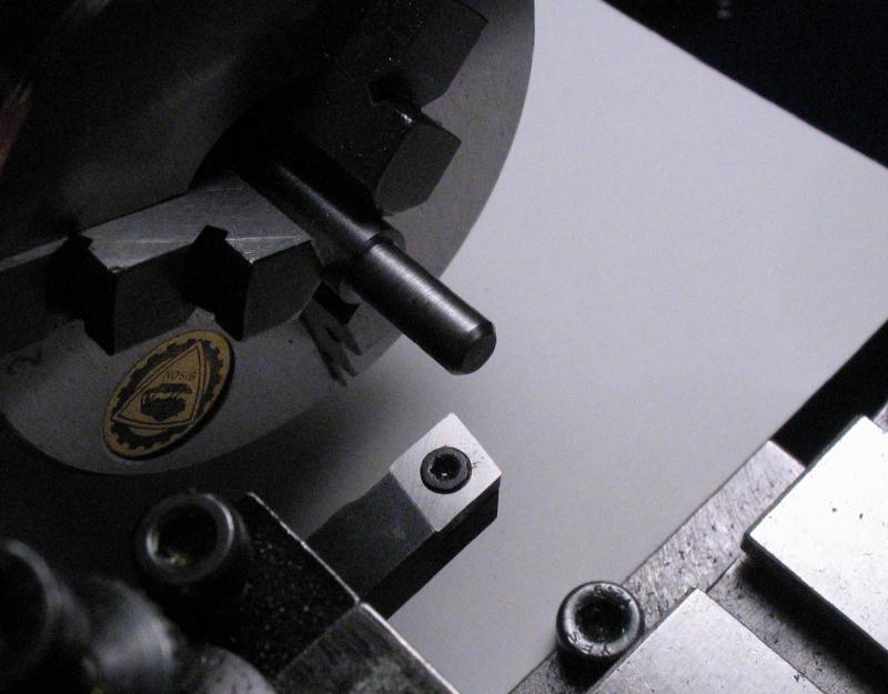
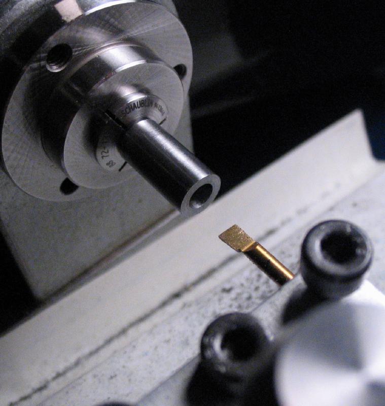
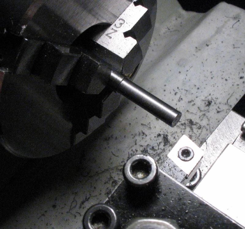
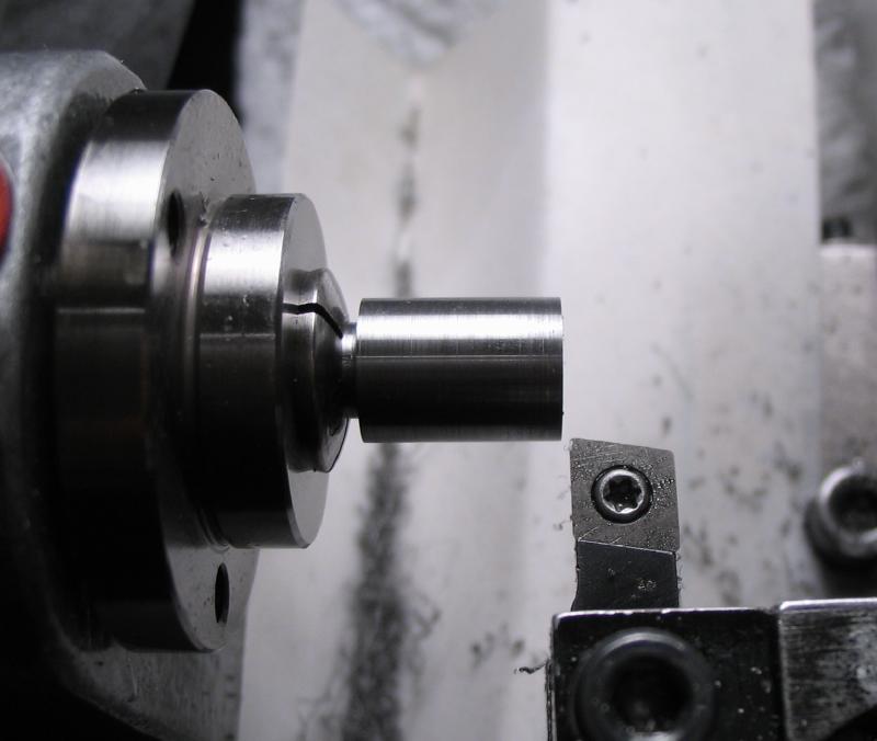
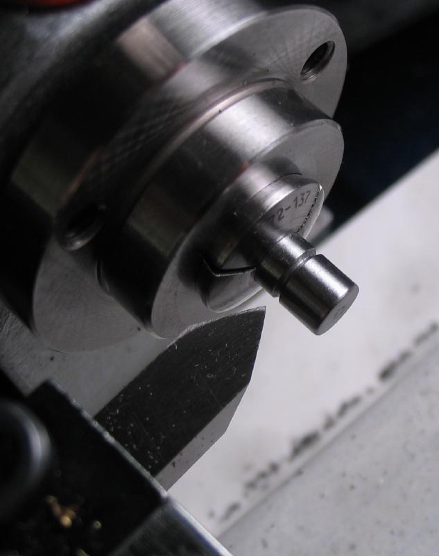
The pilot for the cutter was made from 1/8" drill rod, a slight taper is turned on the end. The pilot was then parted off.
Relief was filed on the cutting tips.
 |
 |
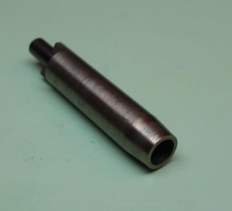
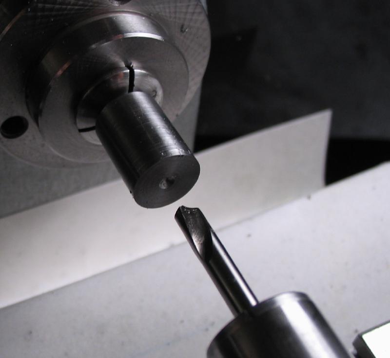
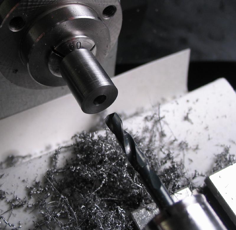
To make use of the available steel, the reverse end was drilled 4mm and tapered ~7 degrees. This end of the tool will be used later for forming a radius, but was machined prior to hardening and tempering.
The cutter and the pilot are hardened in oil and polished to observe color change during tempering.
The cutter was tempered to light straw and the pilot to purple
The cutting edges can be touched up with a Arkansas slipstone.
 |
 |
This counterbore was made to fit a 8-32 socket head screw. It is made in a similar fashion as the one above, except that the relief on the cutting edge is milled instead of filed by hand. The tool was started from 7mm drill rod and the end turned down to 5mm. The work is reversed and drilled 4mm. The work is transferred to a collet and the hole is then bored to 4.2mm.
|
|
|
|
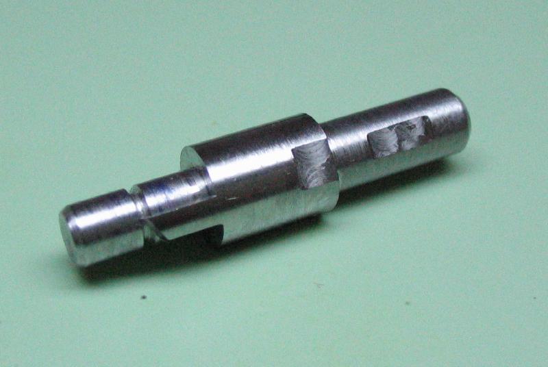
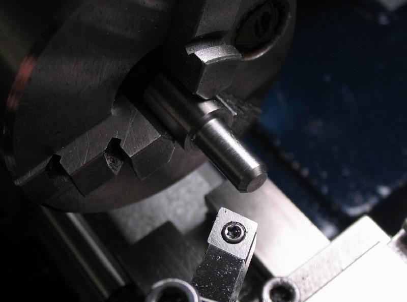
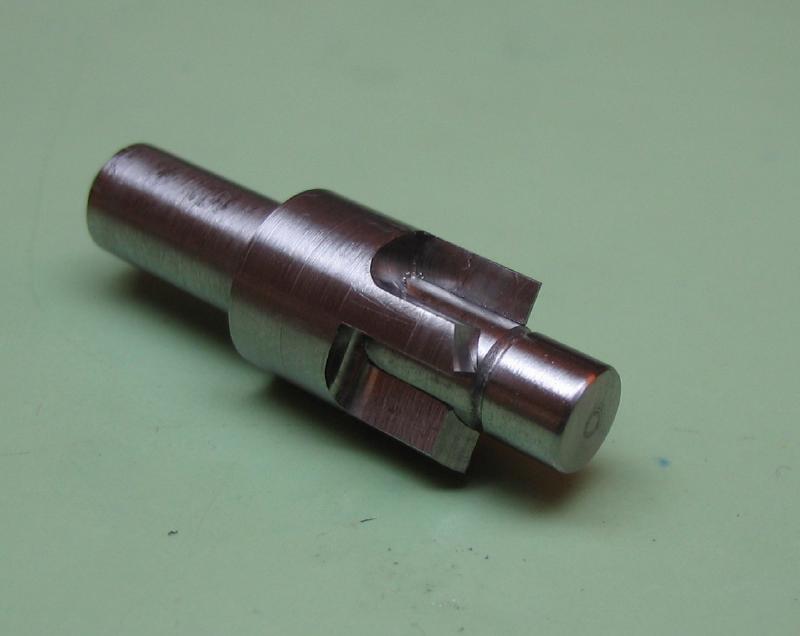
The work is reversed and held in a 7mm collet in the dividing head to mill reference flats on the shank and on the 7mm diameter portion for reference after reversing the work back into a 5mm collet for milling the tip.

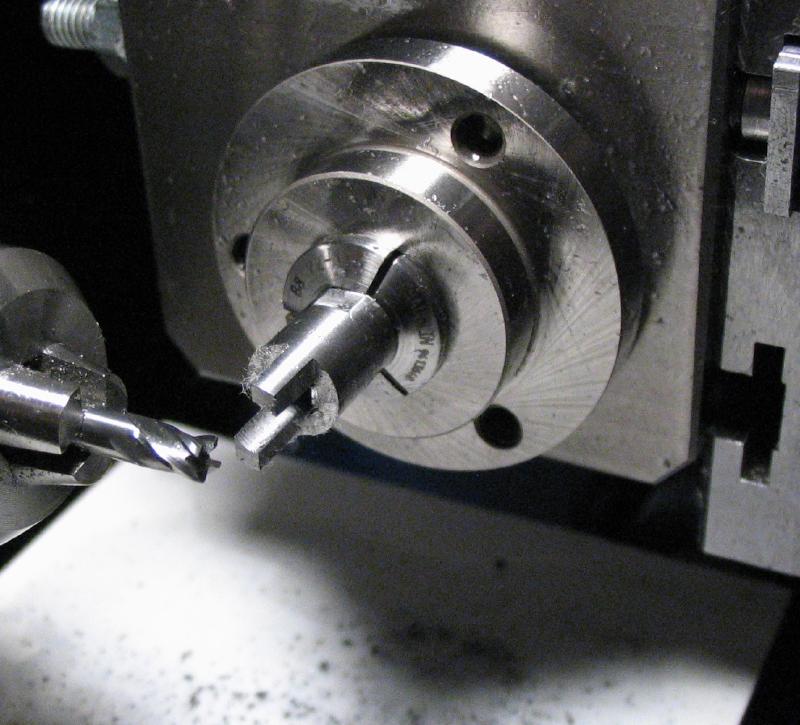
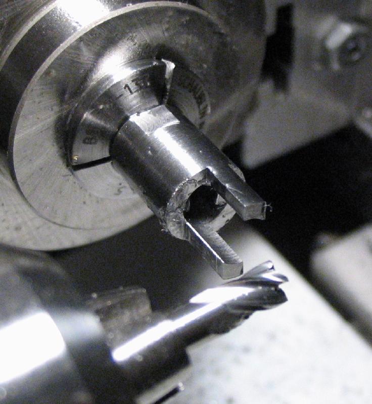
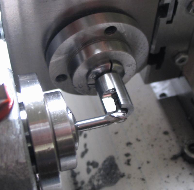
The cutter faces are milled using the dividing head on the vertical slide and a 1/8" endmill. They are milled to the center line with about 1.8mm thick.
|
|
The cutter is then setup for milling the cutting edge relief. It is held in the 5mm fly-cutter holder, which is mounted in the collet-holding tool block. The flats on the shank are used to index the cutter in the fly-cutter holder.

|
|
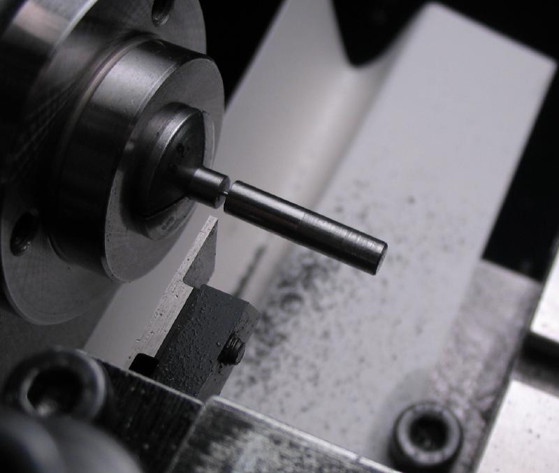
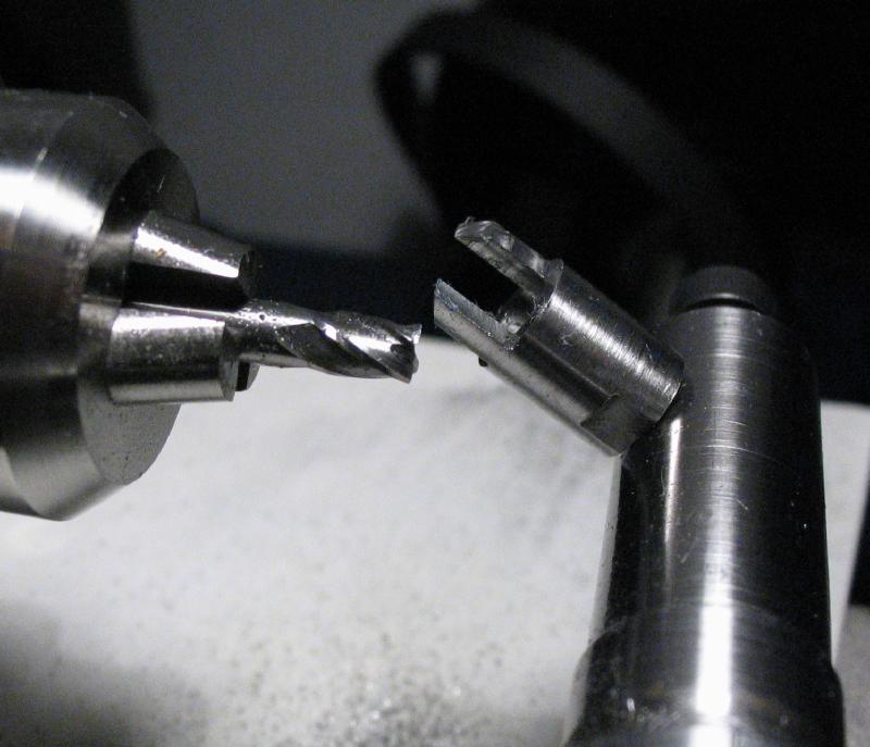
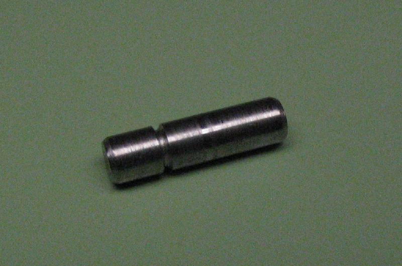
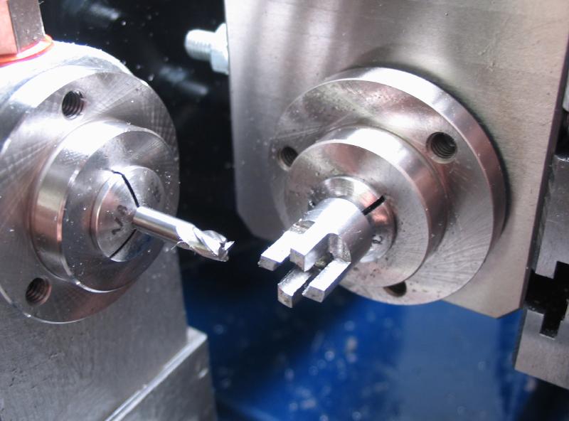
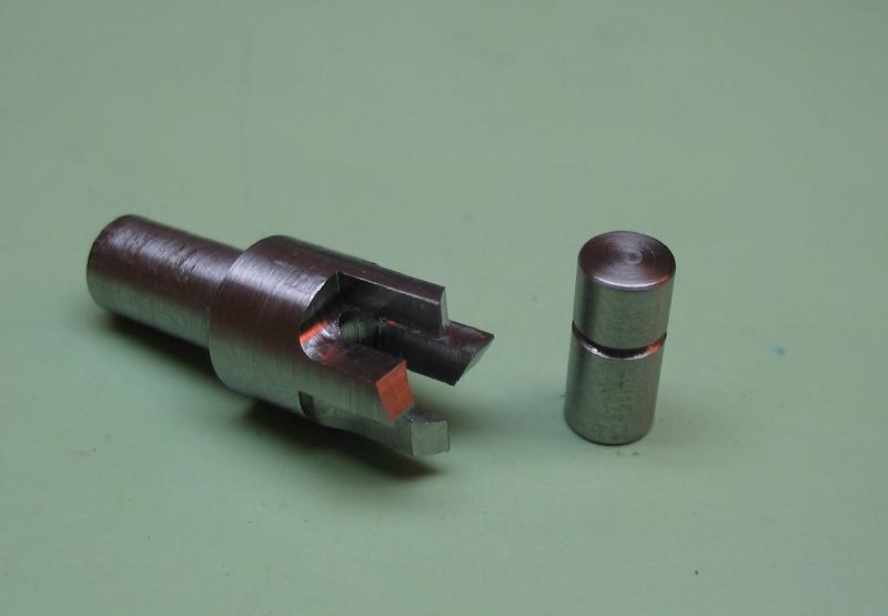
A pilot pin was turned from 5mm O-1 drill rod to 4.2mm and parted off. A vee-groove was turned to provide clearance at the cutting edge, and the pin is then chamfered on both ends.
|
|
|
|
|
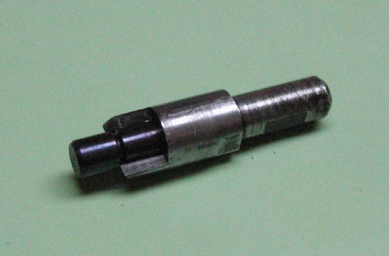
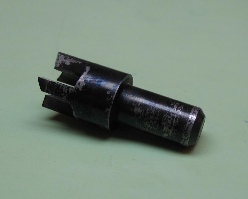
The components were then hardened in oil and the pilot pin tempered to blue. The cutter can be tempered to a very light straw, and the edges touched up on a oilstone and Arkansas slip stones.
|
|
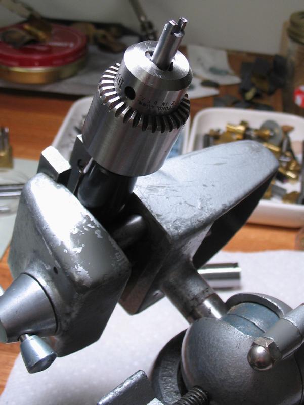
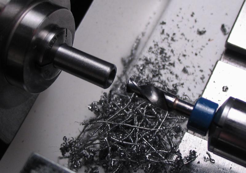
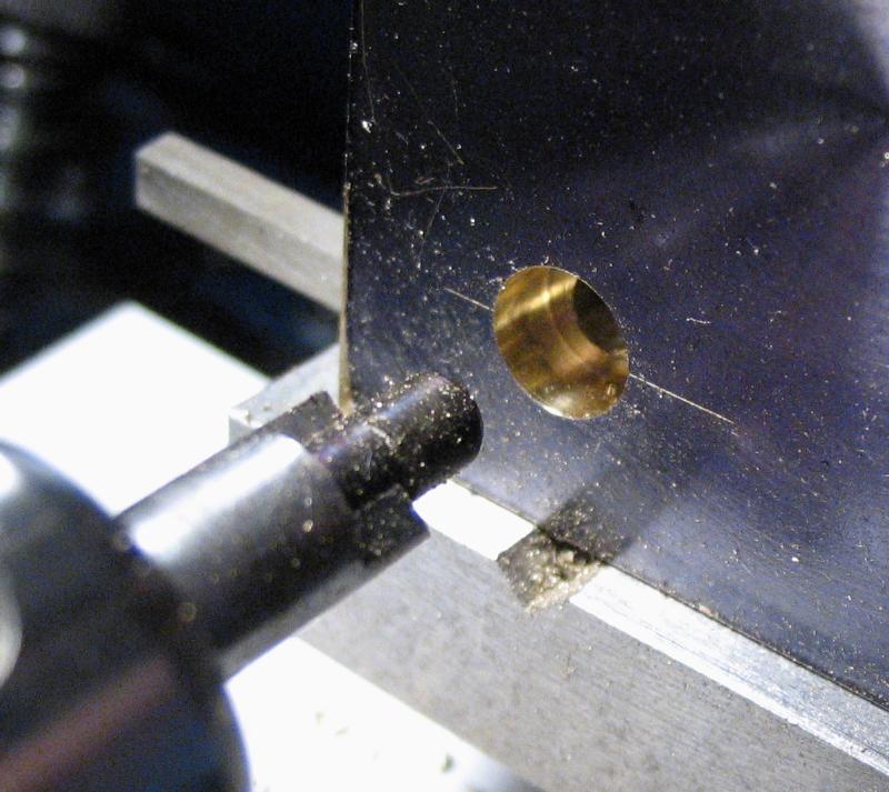
This cutter worked very well and is shown boring out the space for a socket head screw in a piece of brass plate. The hole was drilled 4.2mm to pass the pilot pin and the cutter was fed at relatively slow feed and speed.
I have previously made counterbores using the John Shadle method and is described in his document below.
| Shadle - Making Pilot Cutters |
Bergeon's current set of cutters and removable pilots (BG-30007-MD) retails for over a $1000 !
| Bergeon 30007 - MD - 15 |
Following the Shadle method, above, the cutter is turned to diameter, drilled for the pilot, and the cutting faces sawn and filed to shape. The pilot is turned from blued pivot steel, and slightly tapered to fit snugly into the cutter. Prior to inserting the pilot, the cutter is hardened and tempered to straw, and cutting edge stoned with an Arkansas slip.
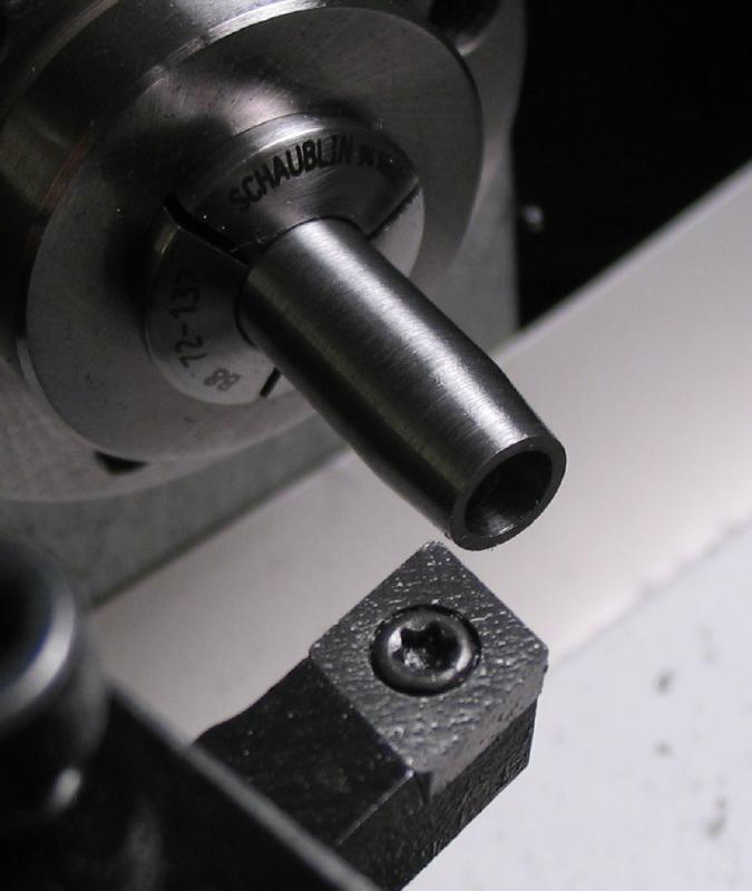
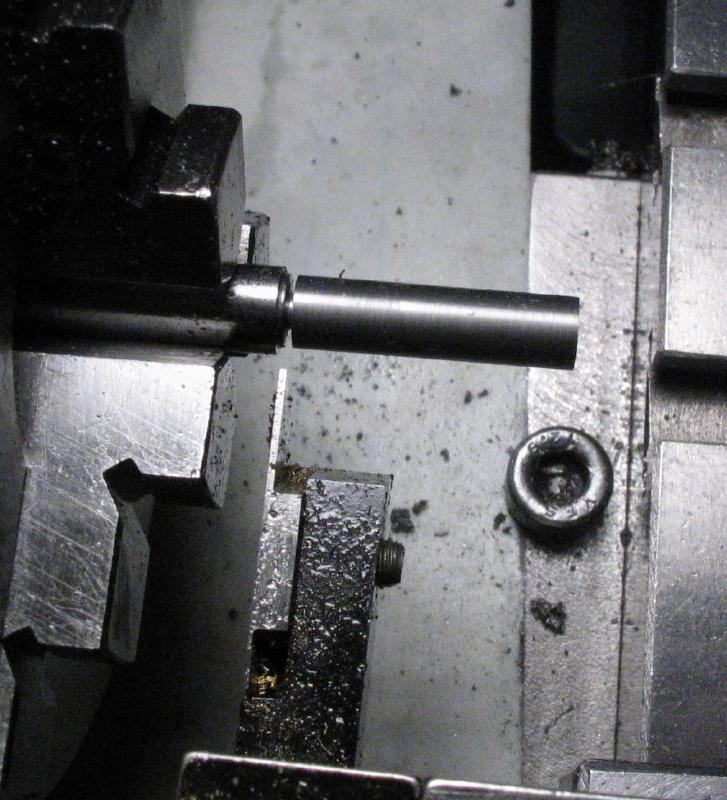
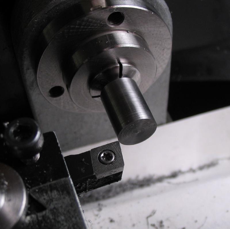
A counterbore was made to form the recess for M5 socket head screws. A one inch length of 10mm O-1 drill rod was turned down to 6.0mm for a length of 13mm, this fits nicely into a 6.0mm collet. A 45 degree chamfer was applied using the topslide.
The work is reversed and held in a collet.
The remaining length of ~12mm was turned to 9.0mm and faced.
|
|
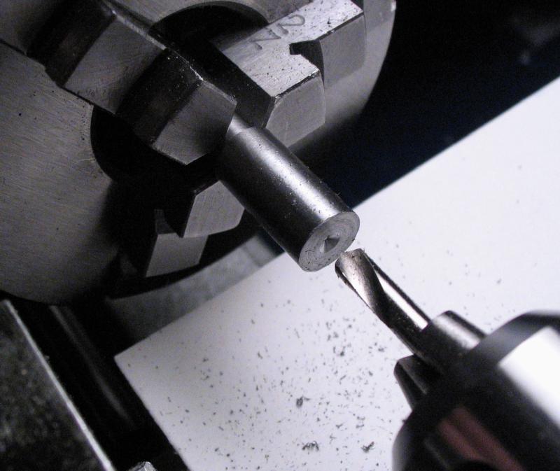
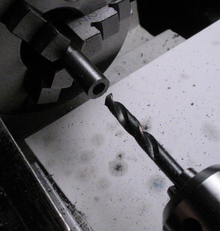
The rod was spot drilled, pilot drilled 3.2mm, and then drilled 4.90mm to a depth of 7mm.

The hole was then reamed to 5.0mm.

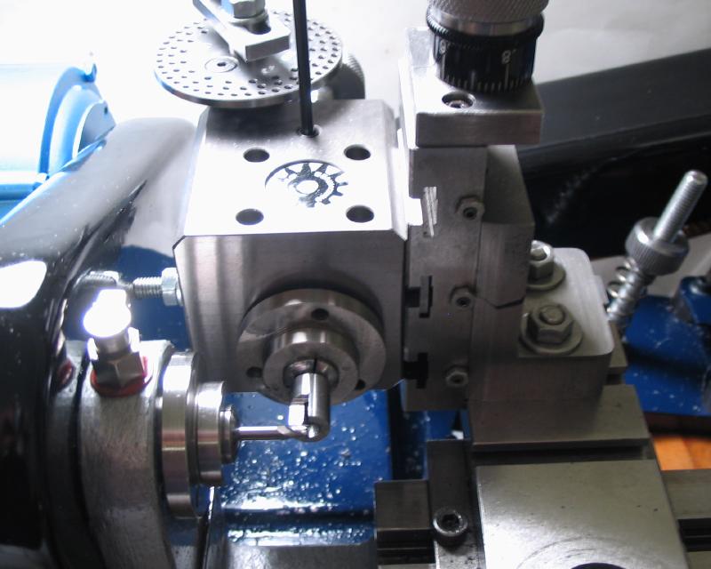
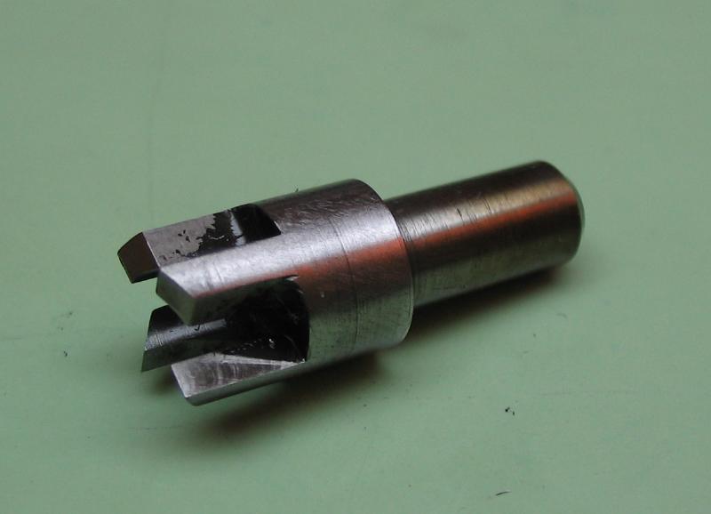
The work is transferred to the dividing head, mounted on the vertical slide. Four cutting faces were milled using a 1/8" endmill. The mill was fed to a depth of 2.5mm, length of 6.3mm and to the center line. The work is indexed through four positions.
|
|
The cutting tip was formed with a 70 degree single angle cutter.
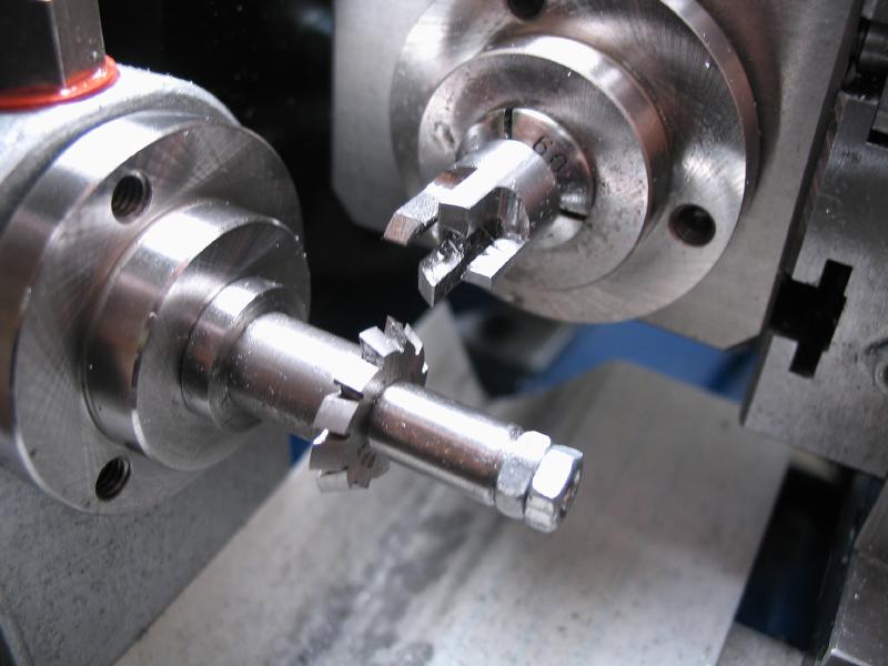
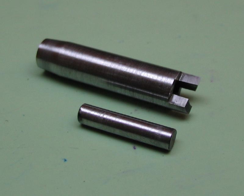
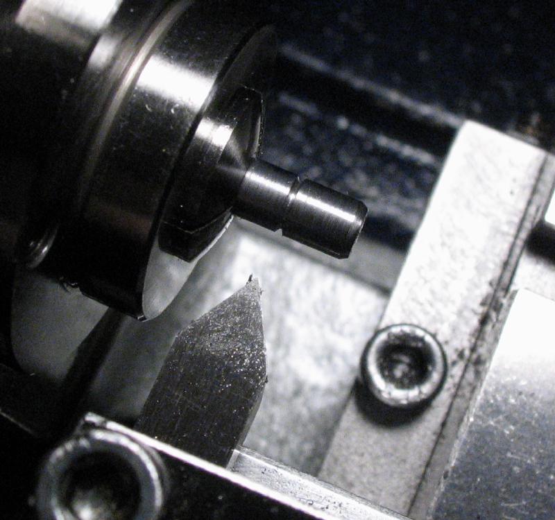
A pilot was made from a half inch length of 5mm drill rod. After facing each end and lightly chamfering, a groove was made 7mm from one end. The hope is that this may provide some additional relief at the cutting edge.
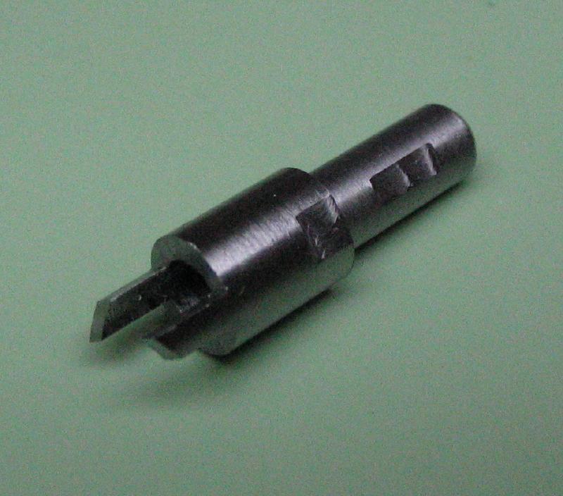
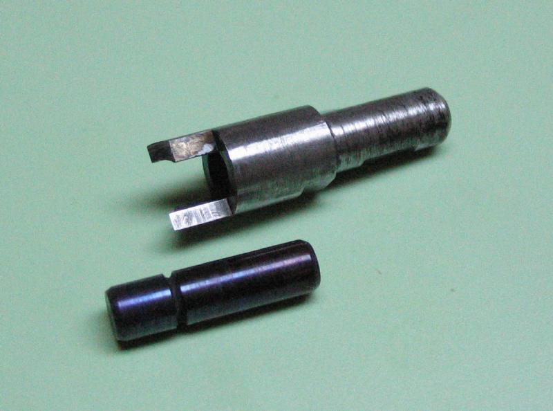
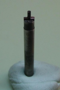
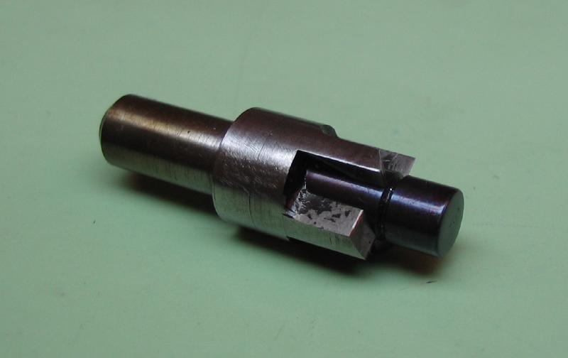
The completed parts.
|

|
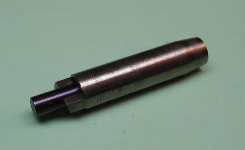
They are hardened in oil. The pilot can then be tempered purple-blue.
|

|
The cutter is polished up with fine oilstone and hard Arkansas slip stones. The cutting faces and relief sides are touched up as well. It is then tempered to a light straw.
|
|
The completed cutter and a M5 socket head screw.