The Ratchet Wheels
The next components to be made are the ratchet wheels or winding wheels. I prefer the simple triangular teeth that Daniels used in many of his watches. P.P. Thornton makes 2 different sizes of ratchet cutters, and I decided on their 60 degree cutter.

I am again about to deviate from Daniels' instruction...
My first attempt at making these wheels ended unsuccessfully, which has proven to be my modus operandi. I, therefore, wasn't especially disappointed, but took this as a lesson in what not to do. My thought process was that I required three identical wheels and rather than make them separately, I planned on milling the ratchet profile into a piece of drill rod that has been turned to proper diameter and then part off the wheels to the proper thickness. Perhaps due to insufficient rigidity or inaccuracy of the three jaw chuck, or some other operator error, the teeth were not formed to a desired perfection. I suspect that if the procedure was repeated with tailstock support, it may work better.
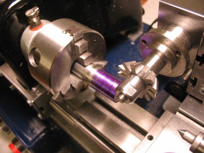
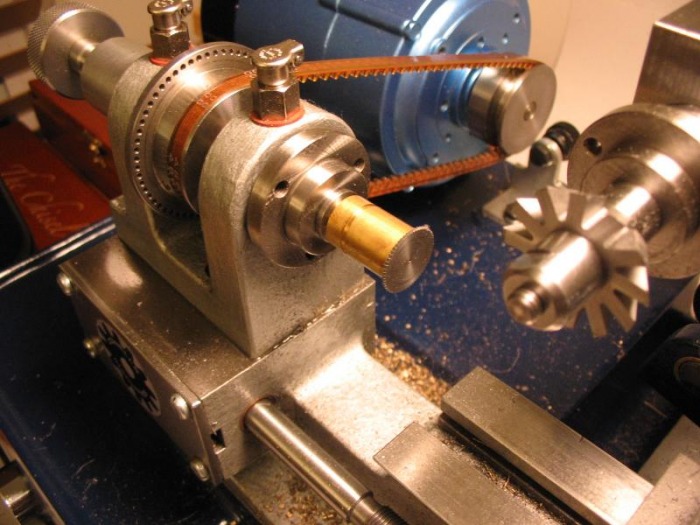
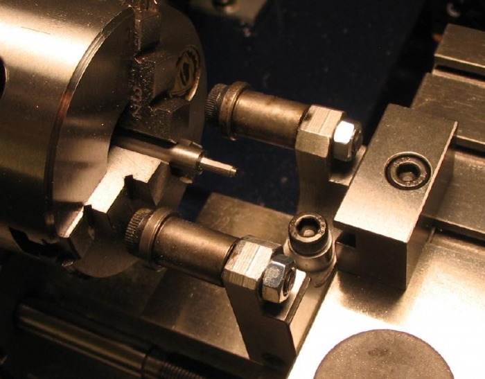
Here is the setup, with the rod turned to 15.7mm and coated in layout blue and ready for milling.
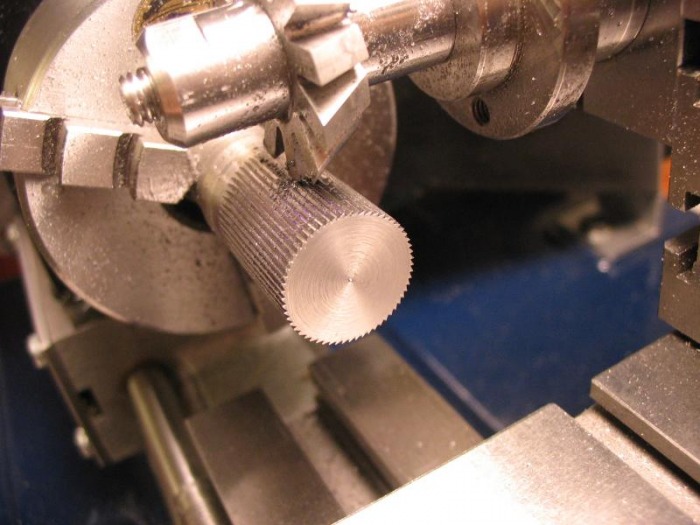
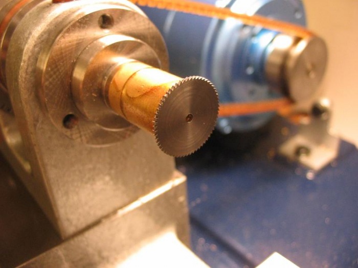
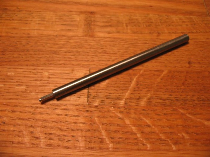
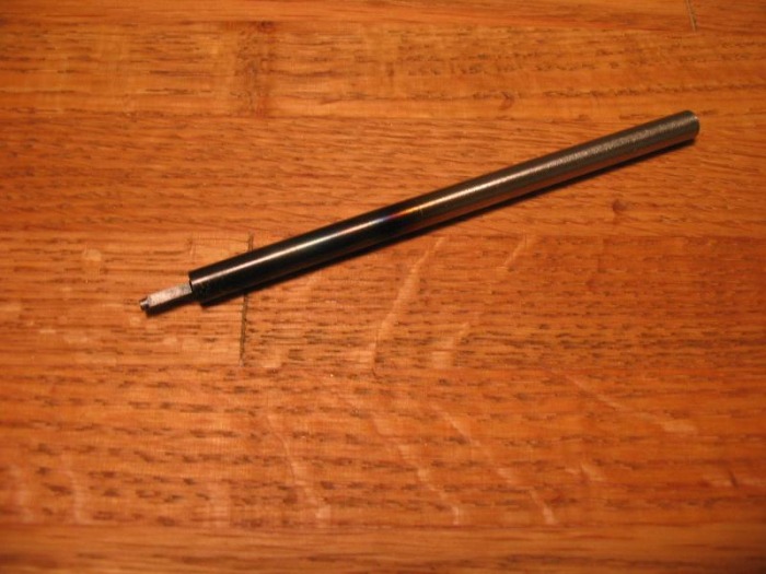
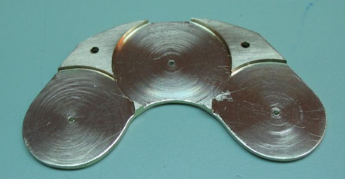
Here is the rod after milling the tooth profiles, although the end wheel looks fine, after parting off several wheels, and examining the teeth, it is apparent that the cutter was not milling consistently, since some of the wheels have shallow, not-completely-formed teeth.
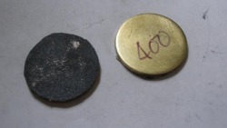
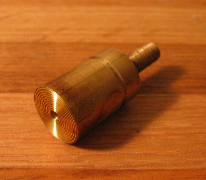
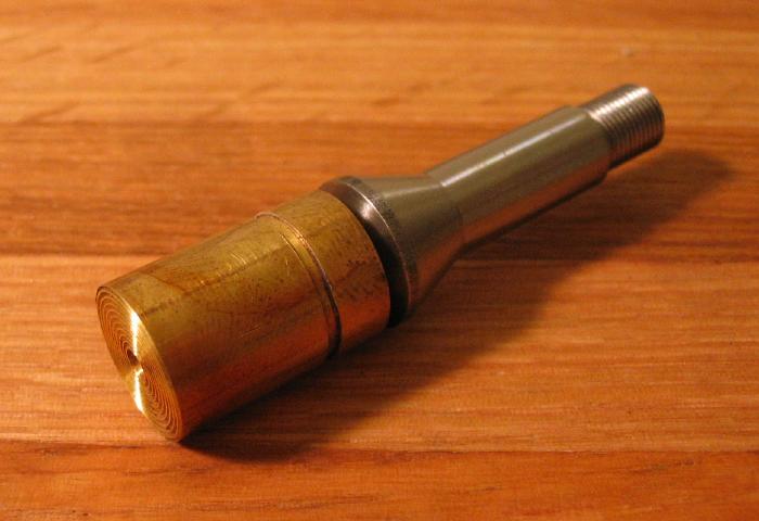
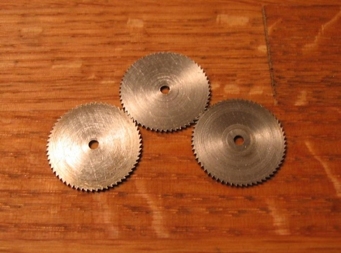
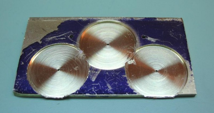
Second attempt; I decided to go with a more direct approach and make the wheels from discs. Starting with 16mm O-1 drill rod, I parted off discs about twice as thick than which is finally required (~1.5mm), and facing the rod after each parting. The faced side of the disc is then adhered to, once again, a super glue arbor. I made a new arbor for this job from ½" brass rod, so that 1) the cutter will not need to cut into the arbor and 2) to allow easy measurement of the thickness and diameter of the disc. Obviously, the photo was taken after I used it a couple times, the discoloring is from heating with a torch to loosen the super-glue.
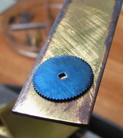
First the disc is faced to the required thickness (0.8mm) and then turned to the diameter which is specified in "Watchmaking" (15.7mm).
Click link below for complete dimensions in PDF format
| ratchet.pdf |

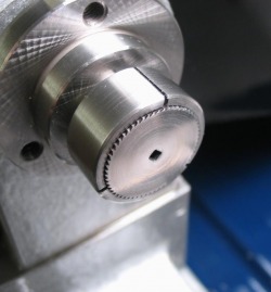
Then the lathe is setup for gear cutting, the ratchet wheel is to have 60 teeth, and I decided to simply use the indexing found on the pulley of the headstock spindle instead of the Cowells G2 index plate.
While still attached to the arbor, the wheel is drilled to prepare it for being broached square later on.
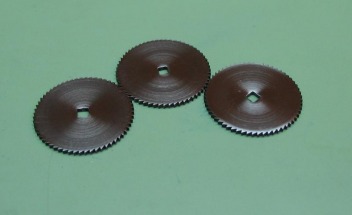
The wheels were lightly stoned to remove burrs left from the milling.
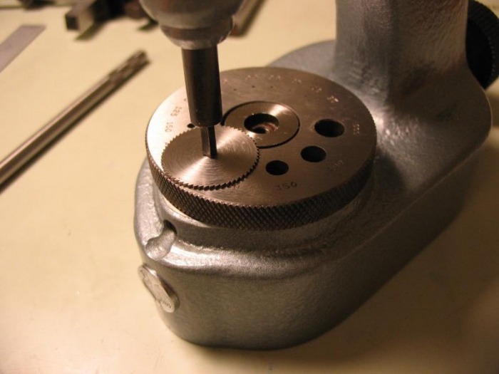
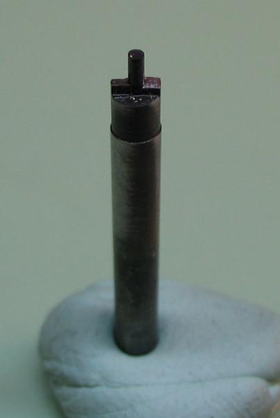
At this stage a square hole is formed by use of a punch or broach, especially made for the task. My staking set uses 5mm diameter stakes. I made a broaching stake from 5mm O-1 drill rod, by turning to the diametric width of the square (2.4mm), and filing a square with the filing rest on the lathe. The leading tip was turned to 1.7mm (the square width) to act as a guide into the finger piece which is drilled 1.7mm. It was hardened in oil and used on the staking anvil.

After filing the square
After hardening
Centering the 2.50mm anvil

Square broach in place
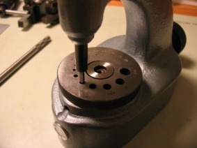
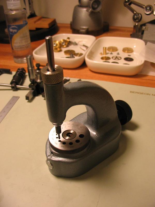
Aligning the ratchet wheel with the 1.7mm tip
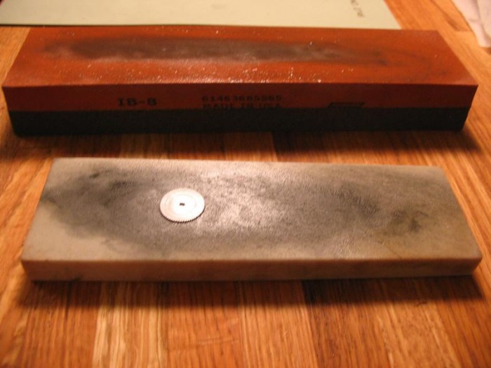
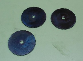
After forming the square hole, the wheels are stoned (fine India then hard Arkansas) to remove the burrs made by the broach
Winding Wheel Bridge
The bridge for the ratchet wheels is made from 1/16" brass plate. Again, Daniels does not provide any details for it construction, and I expect his logic is if you have gotten that far you would not need any details, since it is rather straight forward and not much different from other bridges.
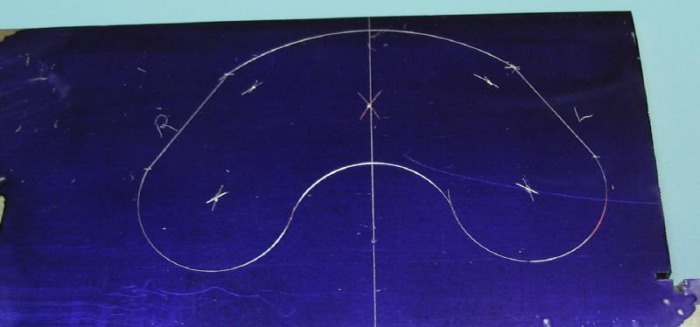
A drawing was made with CAD to get an idea of its basic shape based on the arrangement of the ratchet wheels. Basically, the depthings of the barrels to center pinion are laid out and the depthing of the ratchet wheels to one another are laid out as well. A pleasing shape is then sketched around these points, providing a rigid support, but maximizing space for other components. A print out of my CAD sketch is below.
| winding_wheel_bridge.pdf |
These dimensions are transferred to a piece of brass plate. A convienently placed center punch is made to represent the minute (center) position, and most radii are scribed from there.
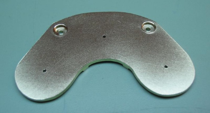
To form the recesses for the screw heads, a pivoted counterbore was made. (see Toolmaking section)
The plate is drilled for ratchet positions with a 0.6mm drill, and the screw positons drilled 1.0mm for the screws and counterbored with the above tool.

From the drillings the recess diameters (16mm) can be scribed on the reverse side and then bored on the lathe using the faceplate and a small boring tool. The depth of the recess is taken from the thickness of the wheel minus the recess in the mainplate (0.1mm). The burrs left in the corners were cleaned up using a small scraper.
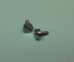
Of course, a pair of screws needed to be made, 1.0mm threads and a 3.0 x 1.0mm head.
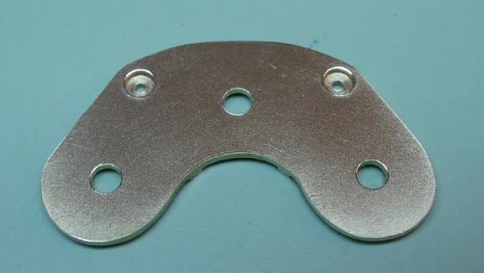
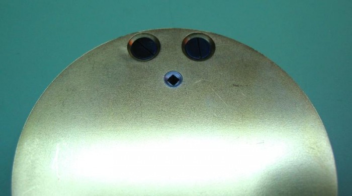
The bridge can then be sawn and filed to the scribed shape.
The holes are bored open to their final diameters (3mm).
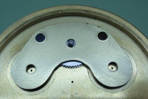
The screw positions can be transferred to the mainplate and the holes drilled and tapped 1.0mm. The recesses for the ratchet wheels can be bored into the surface of the mainplate to a depth of 0.1mm. The pilot hole and couterbore for the winding arbor are formed at this stage as well. All was performed on the faceplate.
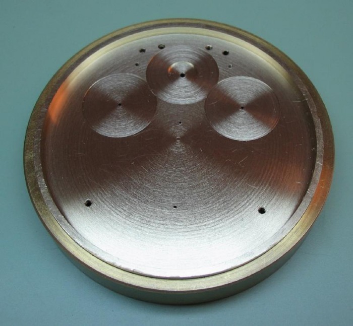
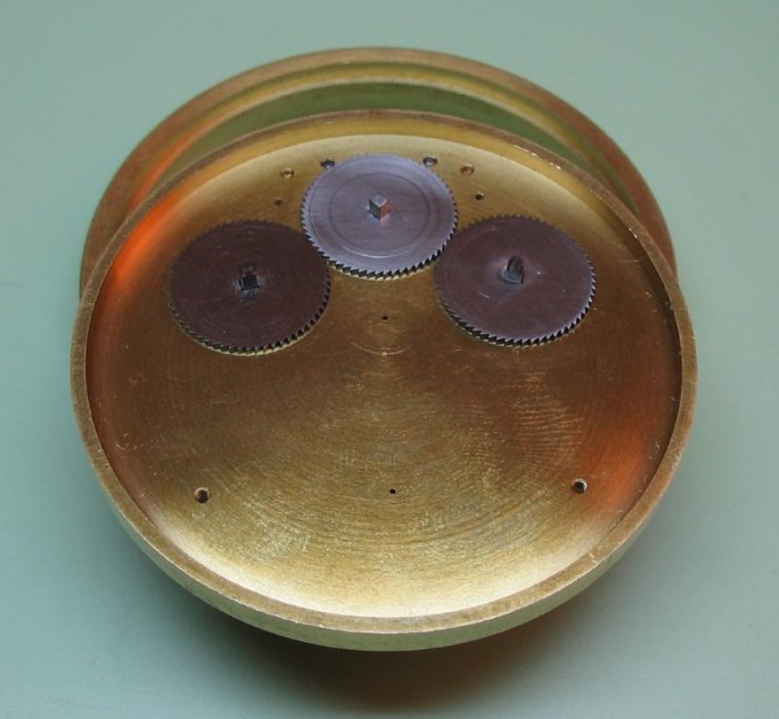
The ratchet wheels can then be tested for their positions.
The winding arbor is fit to the mainplate. The pilot hole is enlarged by drilling and boring to near diameter of the arbor. If the mainplate and bridge are bored together the location is assured. After boring, the hole was lightly broached and finished with a smoothing broach to work harden the surface. This should provide for a durable condition with light lubrication.
Broaches of sufficient diameter are not provided in the Bergeon 30046 (Cutting) and 30075 (Smoothing) broach sets. I ordered several different pairs of 'English Pattern' broaches, they are sold in the Stubbs system of measure.
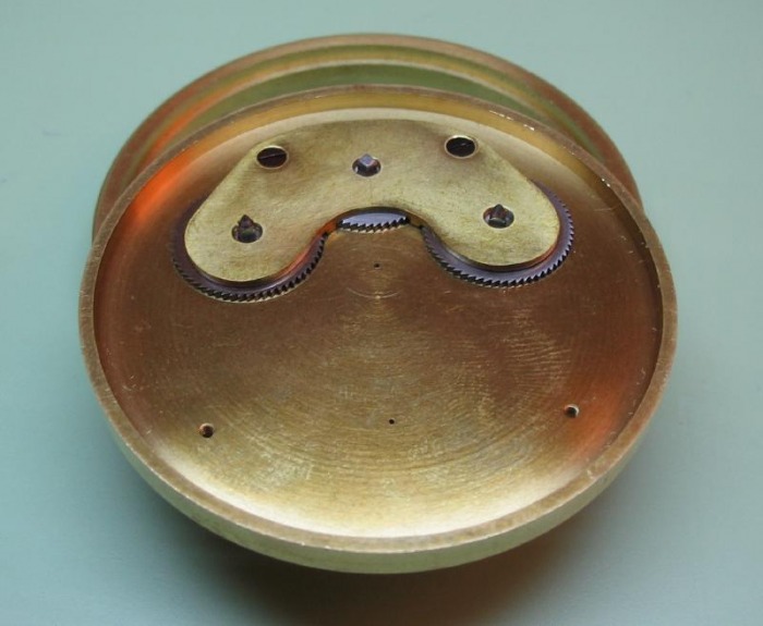
The winding can then be tried, however, the barrel arbors need to be fit to the other ratchet wheels.
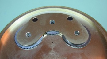
After fitting the barrel arbors (see mainplate section for details), the ratchets can be tried to test thier final positions/interaction.
After reaching the stage above, I was side-tracked into making various other parts. I am finally getting around to finishing the ratchet wheels. They still need to be hardened, tempered and polished. Daniels covers the various finishing methods in the chapter on finishing brass and steel (Chapter 3), rather than covering it in the chapter where the design and making of the ratchets is covered (Chapter 6). He covers frosting and circular polishing using a lap. I decided on a much more simple method.
First the wheels were fully hardened in oil.
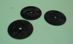
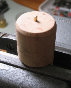
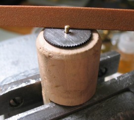
A cork support was cut from a wine bottle cork. A taper pin is inserted to provide a means on holding the wheel in place while stoning the wheel flat with a fine India-stone triangular slip. This helps even out small irregularities and removed any remaining burs from the broaching or tooth cutting.
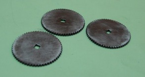
The wheels can then be tempered blue on a brass plate held over the spirit lamp.
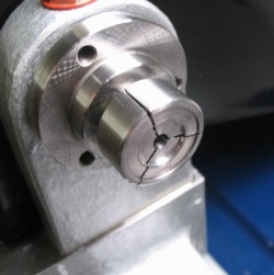
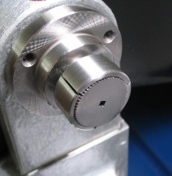
The pot-chuck blank used for the fourth wheel can be bored out to hold ratchet wheels. The bore for the fourth wheel remains, of course, for future use.
Emery paper was attached to brass discs to provide a flat surface and the paper applied to faces of the wheels. This gives a simple circular grain to the wheels.