Face Plate Clamps

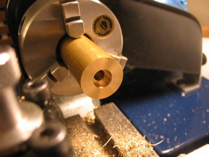
I then chamfered it for aesthetics, and parted it off using the rear tool post with an inverted cut-off bit.
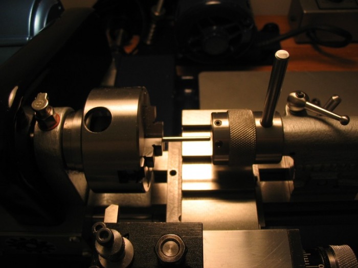
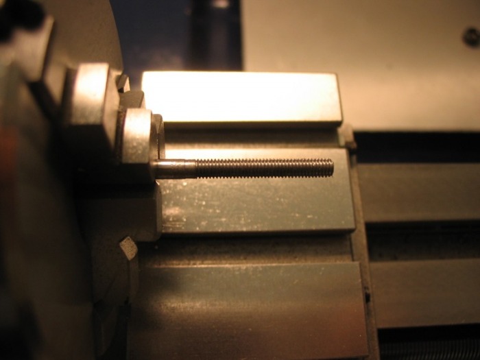
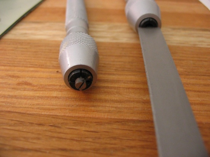
An off center screw is needed to level the clamp while in use. I simply scribed a mark with a compass on each of the 3 clamps and drilled a 2.5mm hole in each using the drilling pad in the tailstock. I tapped these holes with an M3 hand tap. To fit these, and I made several M3 set screws from 3mm O1 drill rod, and cutting a slot with a screwhead file. This seems like a good time to show the Cowells thread cutting setup. The die holder is bored to have a smooth fit the tailstock 'spindle,' and has a tommy bar for assistance in cranking the die. With a little 'TapMagic' the threading is done with little difficulty.
 |
 |
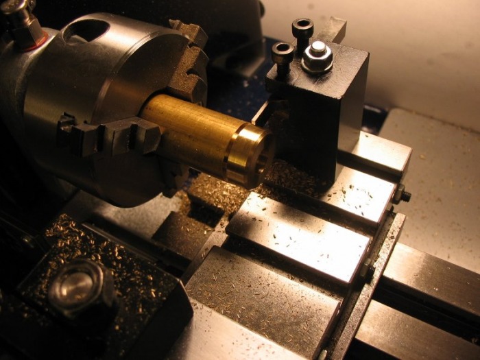
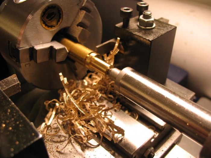
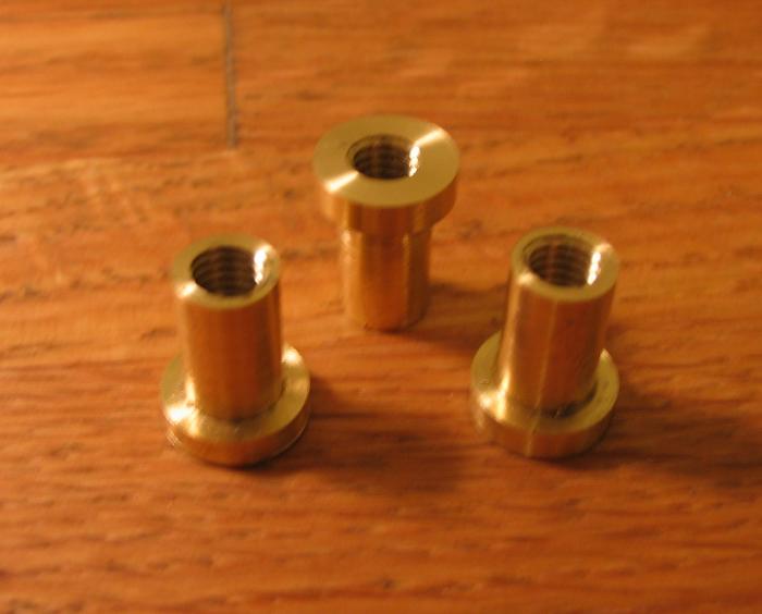
I machined some nuts from 3/8" - 360 brass rod so that they can fit into the faceplate slots. They are simply tapped M5x0.8.
Some nice ribbons of brass....

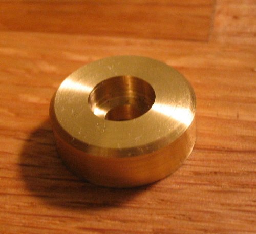
Finished
 |
 |
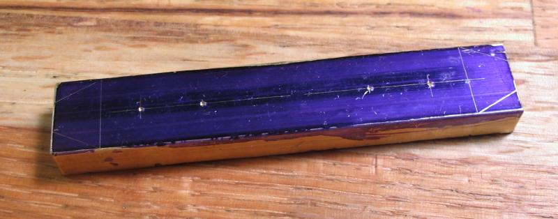
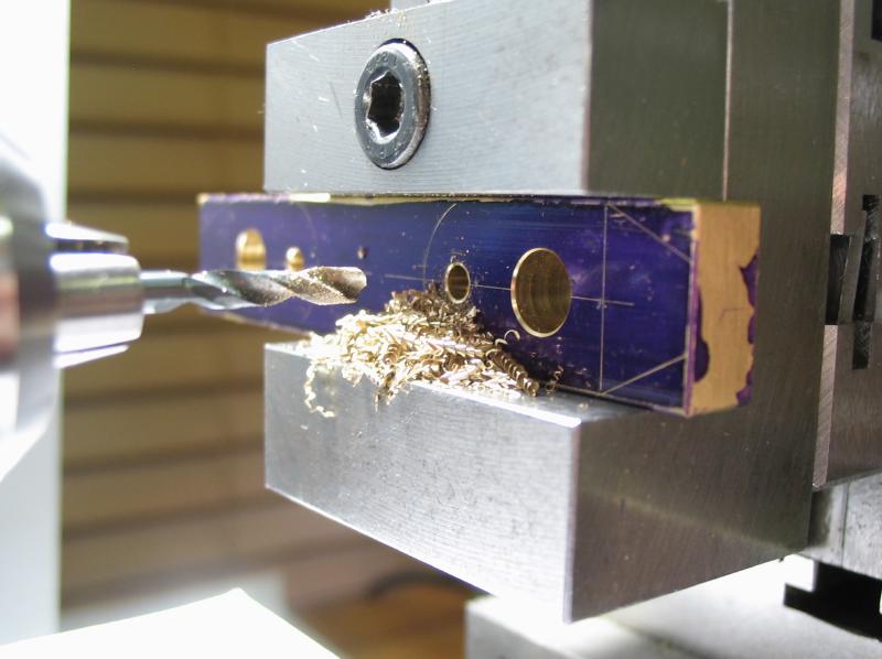
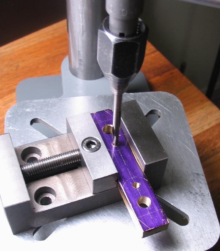
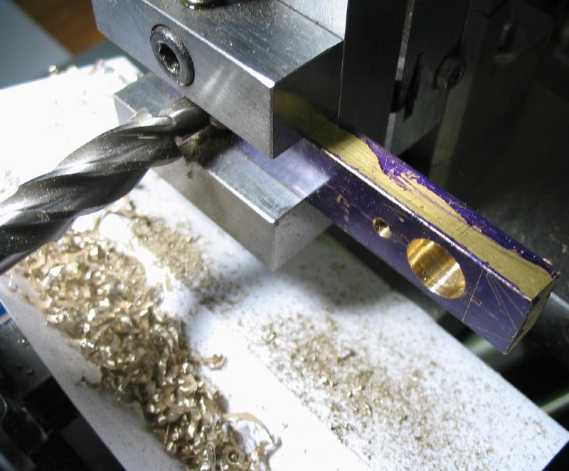
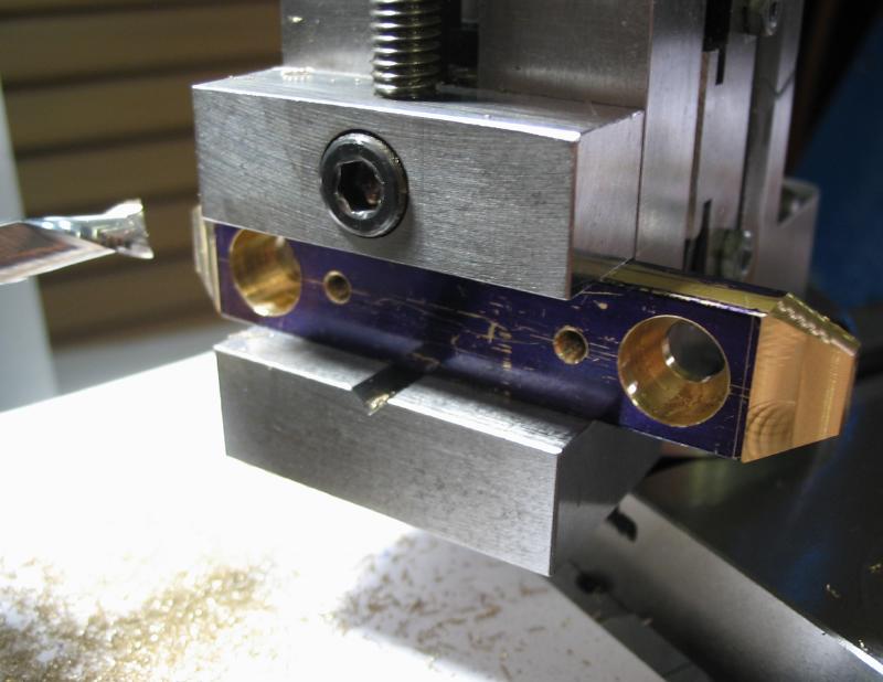
A slightly different style of clamp is described below. They fit the same M5 socket head screws, but made from flat bar rather round rod. A piece of 1/4" x 1/2" brass bar was milled flat on the ends and positions for socket head screws and M3 set screws laid out to make a pair of clamps. The holes were drilled, or counterbored or tapped as required.
|
|
|
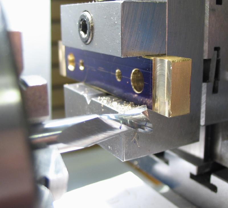
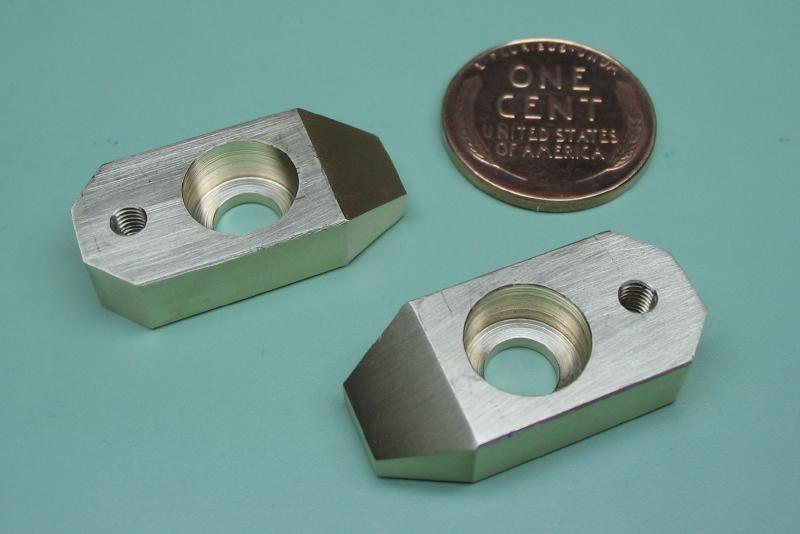
The underside of the clamping ends were milled to a depth of 0.4mm, and the corners and top faces were milled to angle of 25°.
|
|
|
|
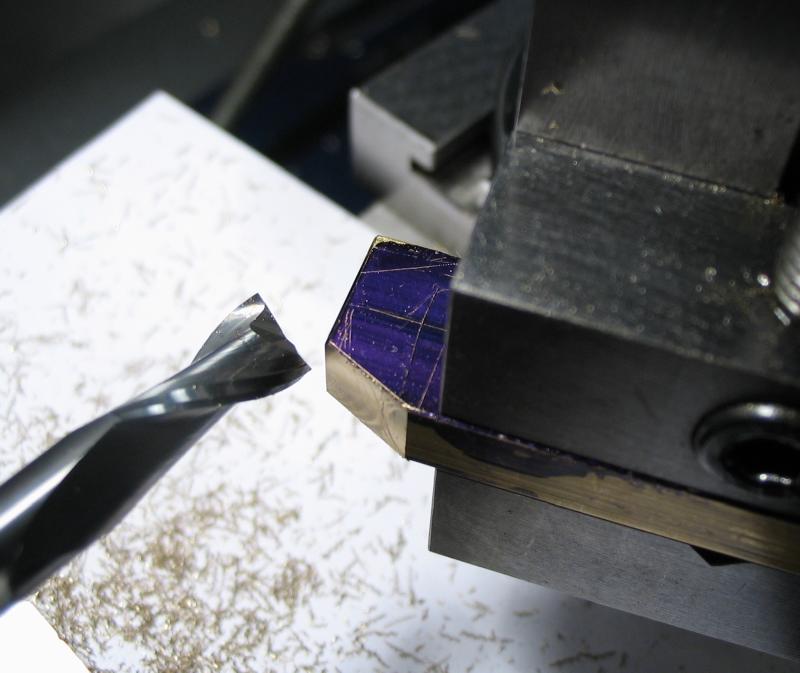
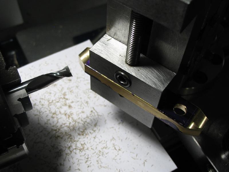
The clamps were parted on the power hack saw (sorry for the blurry shot), and the corners on the sawed ends then relieved 45° by milling.

|

|
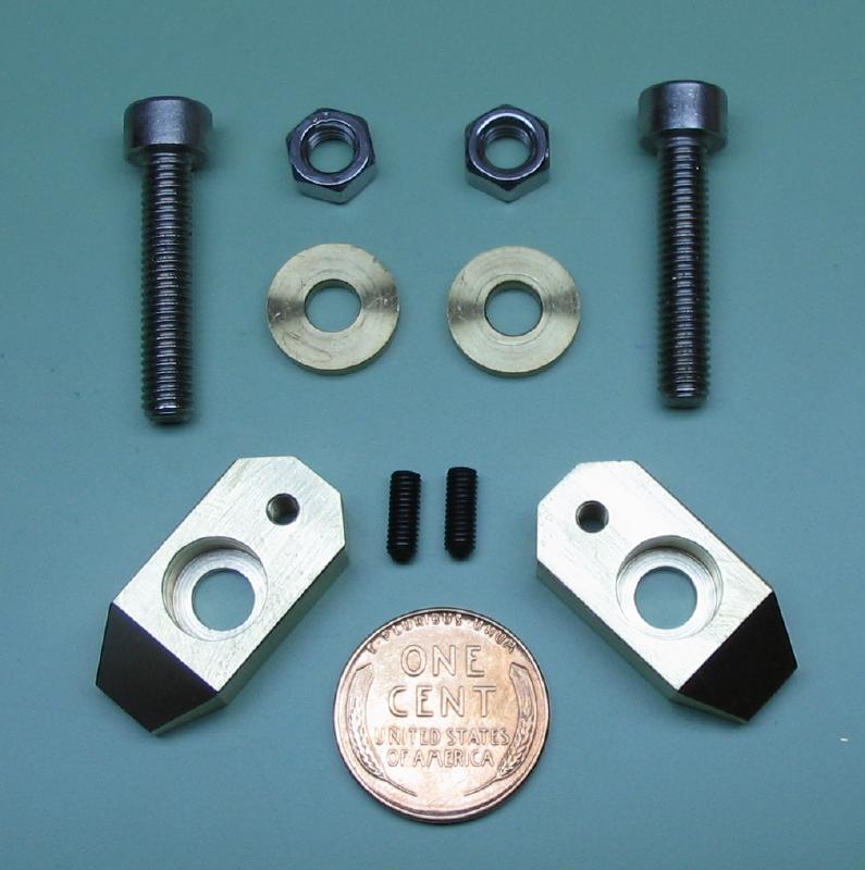
The surfaces of the clamps were finished with a hand file and emery paper. The hardware includes two M3 x 8mm set screw and two M5 socket head screws (20mm length would do, but these are 25mm), matching hex nuts, and washers made previously from 1/2" brass rod.
|
|
