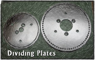
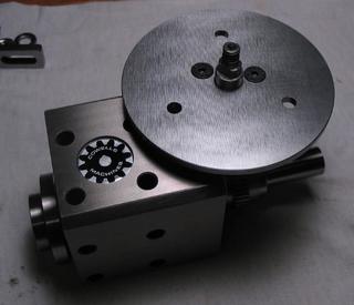
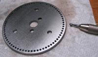
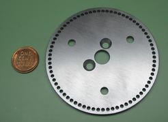
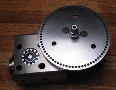
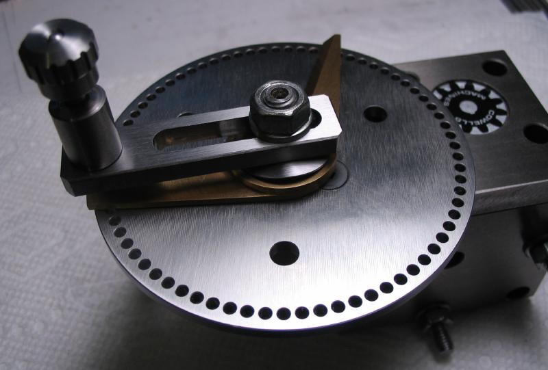
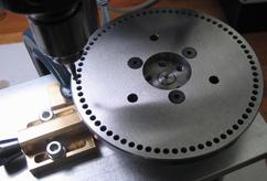
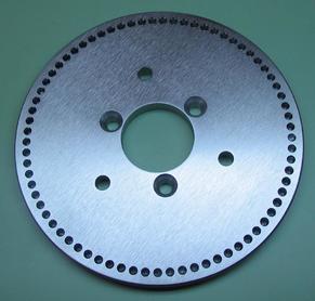
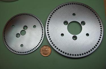
The largest hole count on the set of plates to my dividing head is 49, and I have a need in mind for a count of 73, which is a prime number, so a custom plate will be needed. The plate will need to be larger in diameter than a standard plate, so a replacement detent and longer arm will be needed as well.
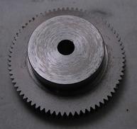
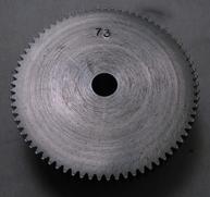
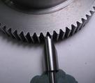
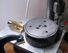
A spur gear with a tooth count of 73 will be used to provide the required number of divisions while drilling the positions into the plate. This gear was found as-is, and is 3 inches in diameter with a 3/8" bore. It is a bit too large and heavy for my initial plans of modifying it for use as a lathe attachment itself. Instead, a jig was constructed that pivots the gear on a stud and uses a detent to lock in tooth spaces of the gear.
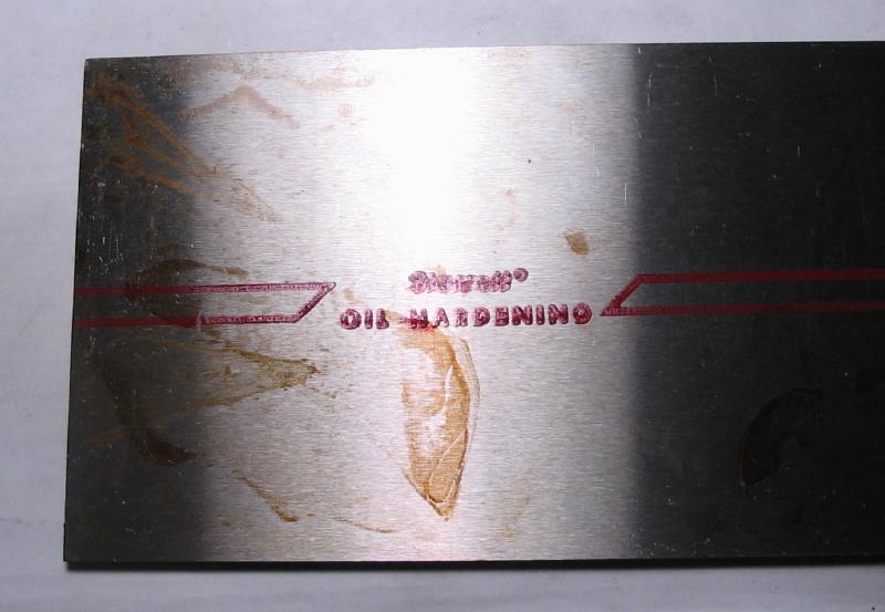
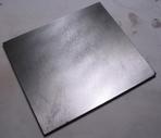
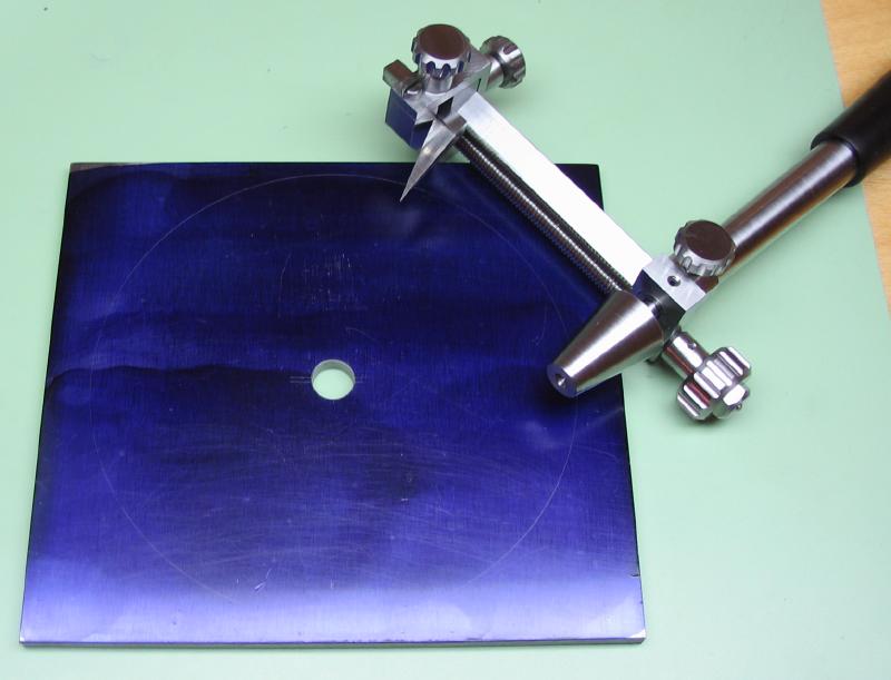
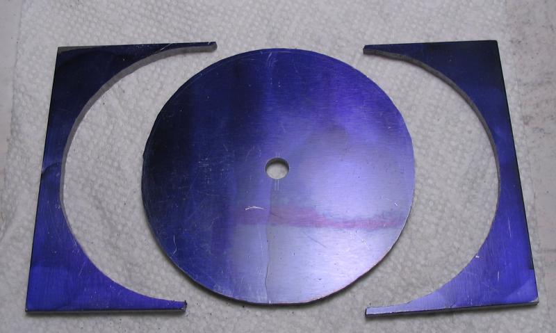
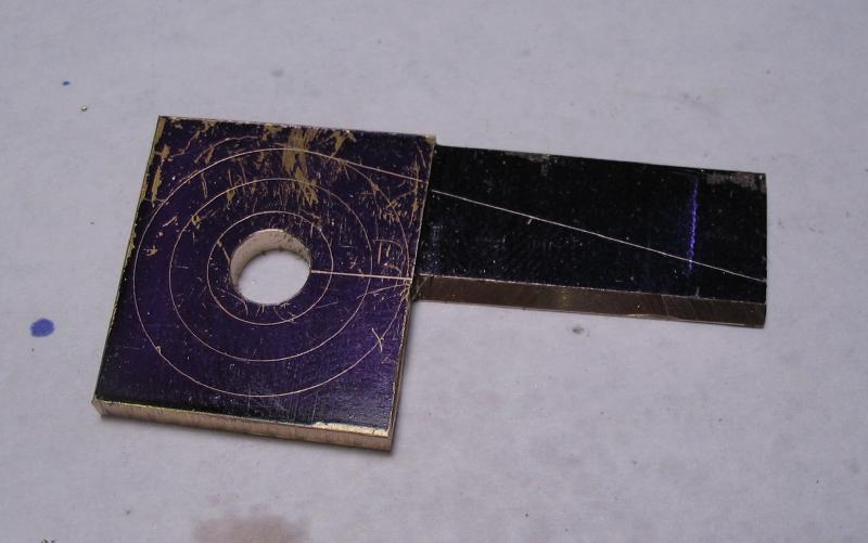
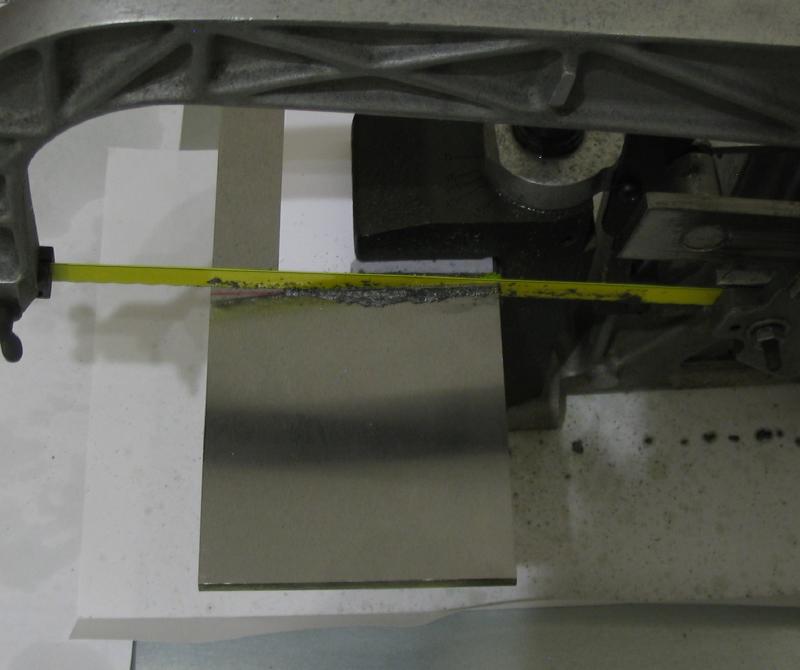
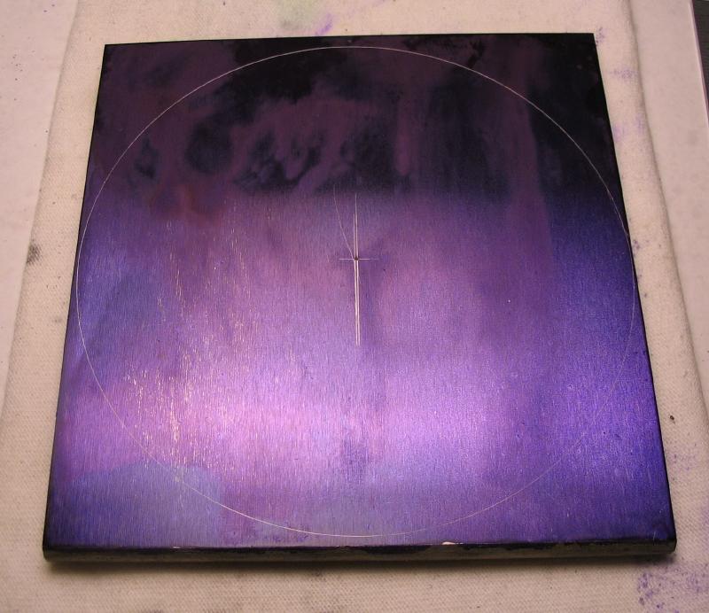
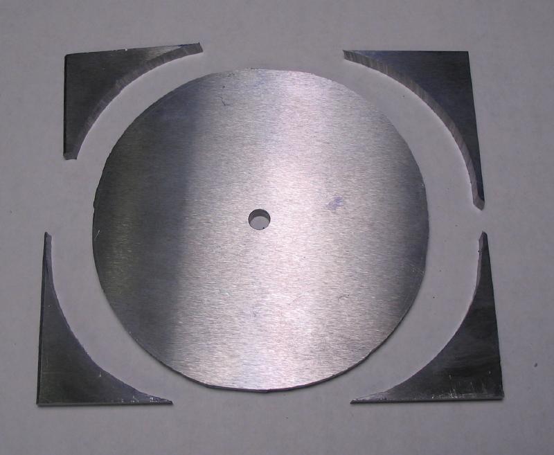
The division plate blank was started from 1/8" x 3 1/2" oil hardening steel plate. I obtained a piece of old stock that has some oxidation or residue, but was available at a very favorable price. A roughly 3" length was sawed off and the surface cleaned up with 400 grit emery paper, however, the surface is still fairly coarse from the manufacturer's grinding. The center of the plate was roughly located and drilled 1/4". This hole will eventually need to be 10mm, but I am taking a round-about route in machining simply due to the dimensions of the plate, which exceed my chuck-holding, drilling, and reaming capacities. The desired diameter could have been laid out from the initial center punch with a divider, but this was an excuse to try my recently made compass. A 75mm circle was scribed and the disc roughly sawed out with a jewelers saw.
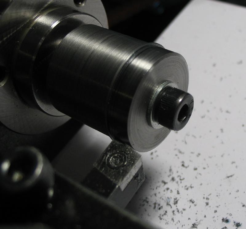
The plate was held on the lathe with a Levin grinding wheel arbor. It was turned round and left at about 76mm diameter and the corners chamfered 45 degrees to remove sharp edge.
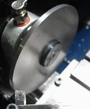
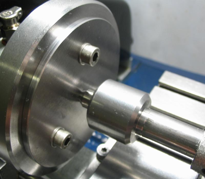
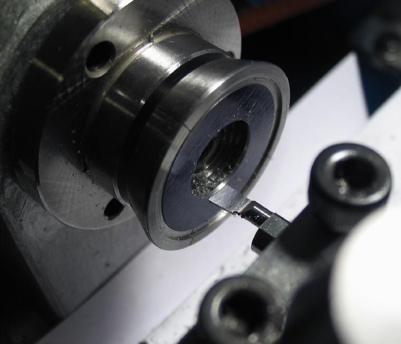
The work was moved to the dividing head and three 5mm holes drilled. These holes were used to fix the plate to the lathe faceplate. The tailstock center was used to help bring the work on center before tightening up the bolts, and the center hole then bored open to 10mm.
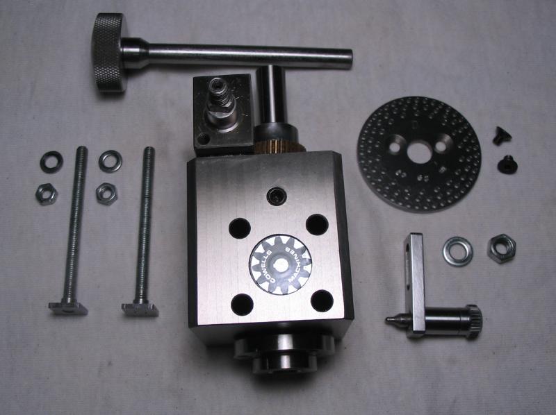
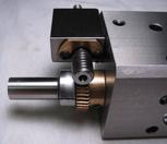
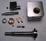
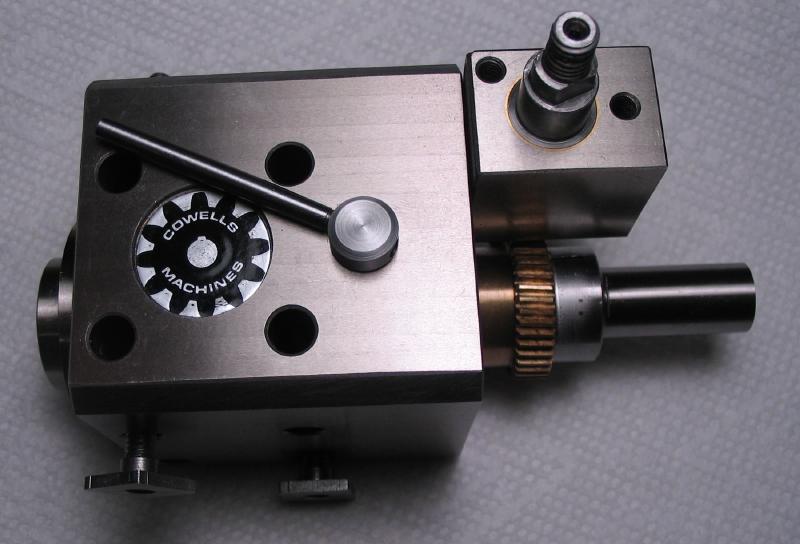
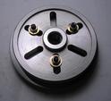
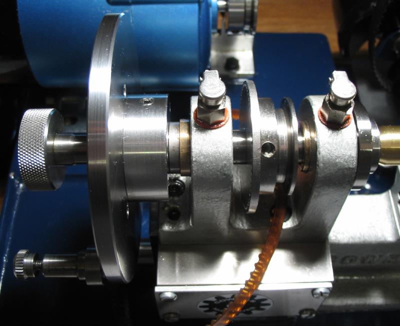
The dividing head was taken to pieces for a thorough cleaning and a couple photos taken in the process. It did not need to be fully disassembled for the task at hand, but I had not done so since purchasing it. My intent was to free up the part of the dividing head to which the plates attach. It was used to lay out the screw positions for a couple steps described below.
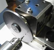
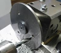
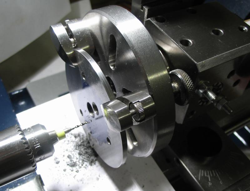
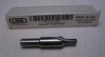
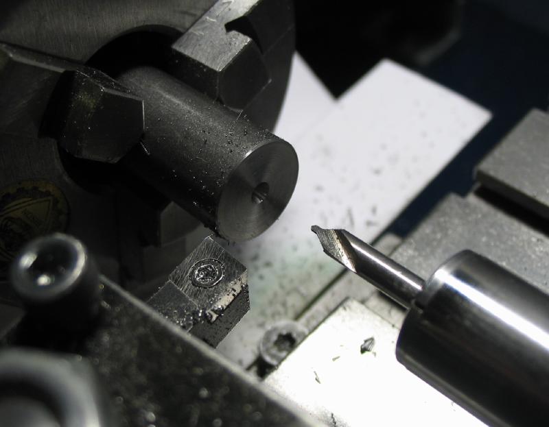
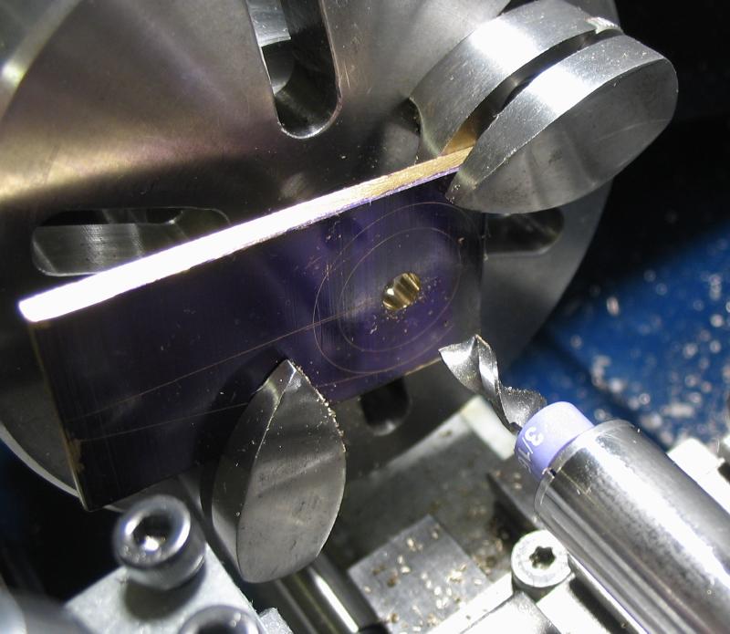
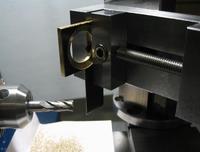
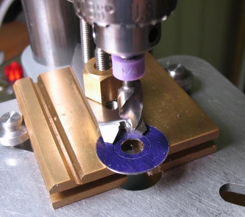
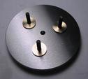
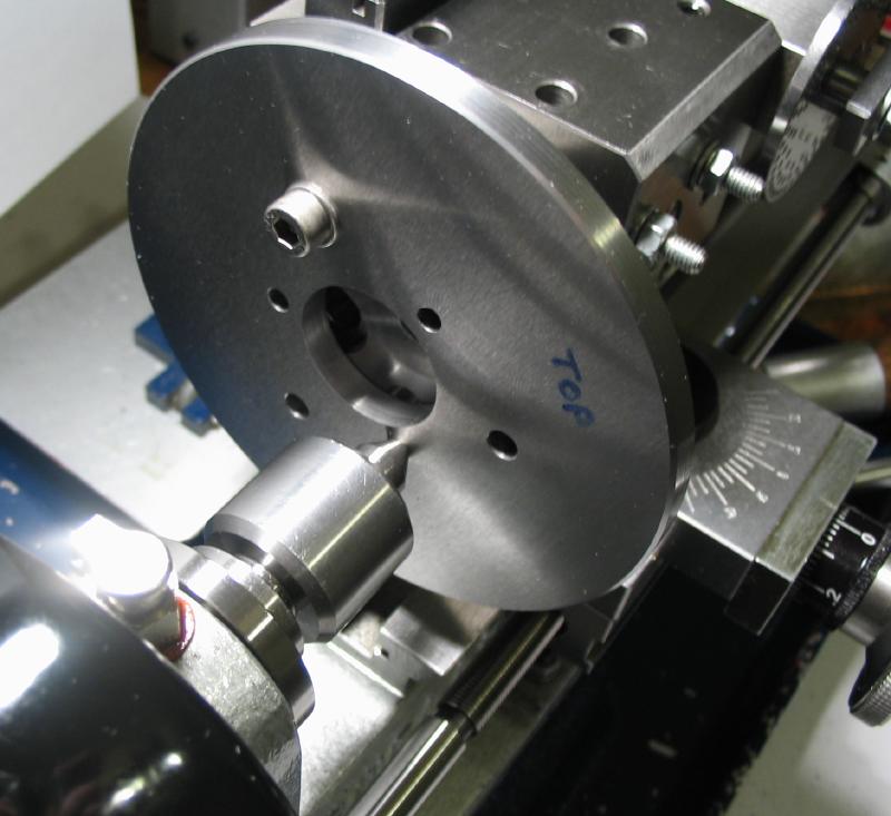
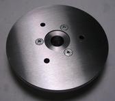
The position for two M4 countersunk head screws were laid out with the compass (10mm radius) and with M4 transfer screws inserted into the plate holder of the dividing head (also the bearing for the worm screw arbor). The worm screw arbor is a slip fit and passes through the 10mm center hole of the plate. The back was tapped with a brass mallet to transfer the positions to the plate. The plate was positioned on the faceplate with clamps and mounted to the dividing head and vertical slide of the lathe to drill the two screw positions. A 1/16" pilot hole was drilled and followed with a combination drill and 90 degree countersink bit specially made for M4 screws.
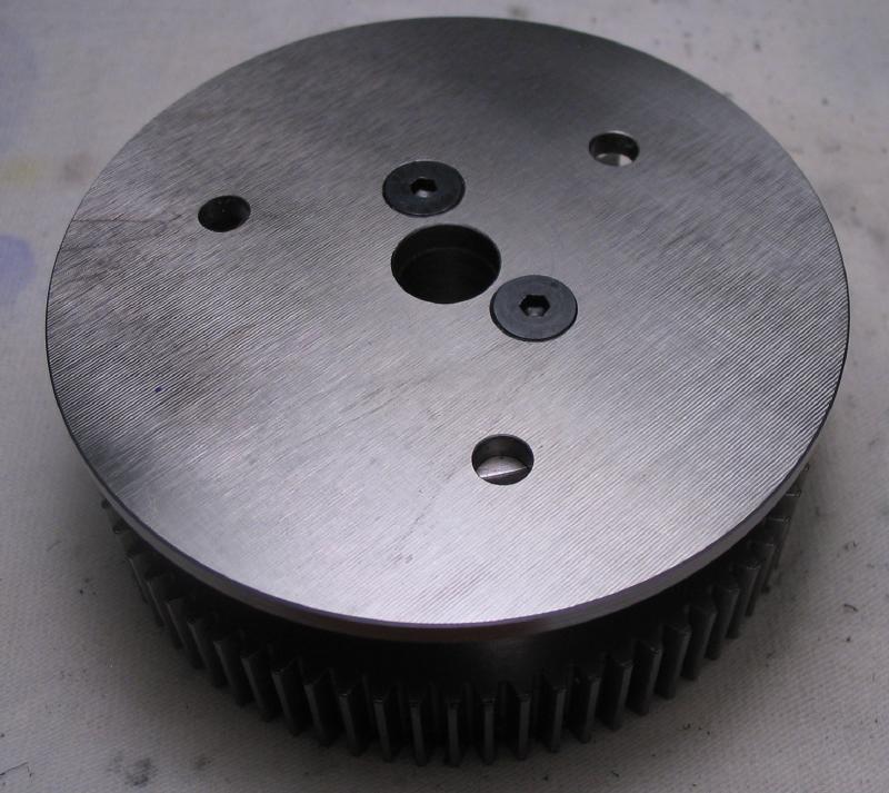
The plate will attach directly to the spur gear for drilling. A 10mm radius was laid out with the compass and a position on this circle chosen and center punched. From the punch mark, the transfer screws in the dividing head component were used like a compass to scribe the second screw position. This position was center punched and both drilled 3.3mm and tapped M4x0.7. The gear was surprisingly easy to machine, I do not know what grade of steel is made from, so expecting a struggle, it was a relief when chips were easily made. It is advisable to drill and tap one hole, attach the plate with a screw and double check the alignment of the second location...
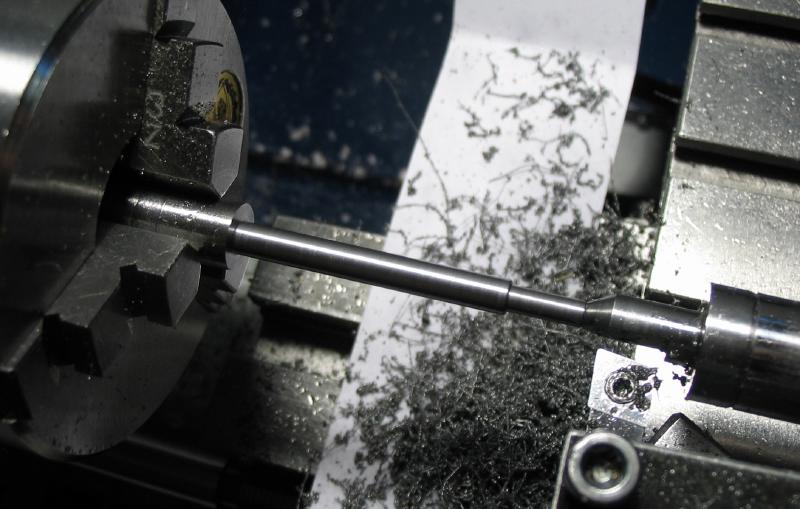
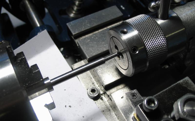
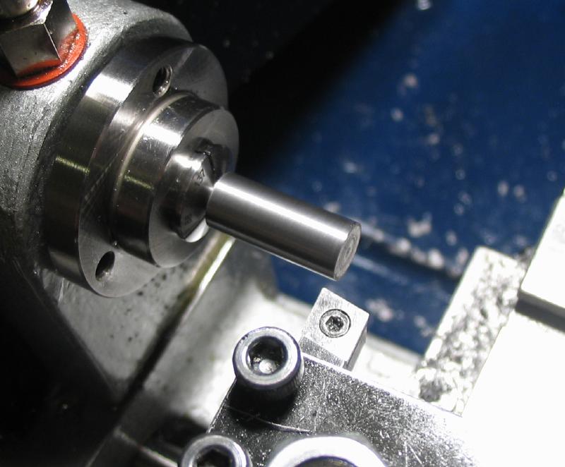
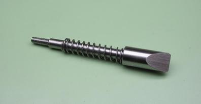
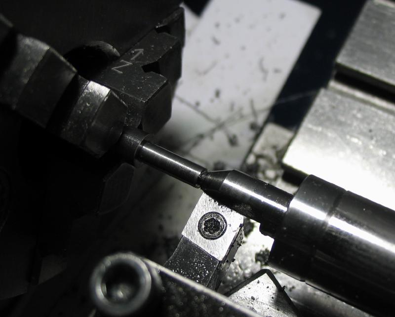
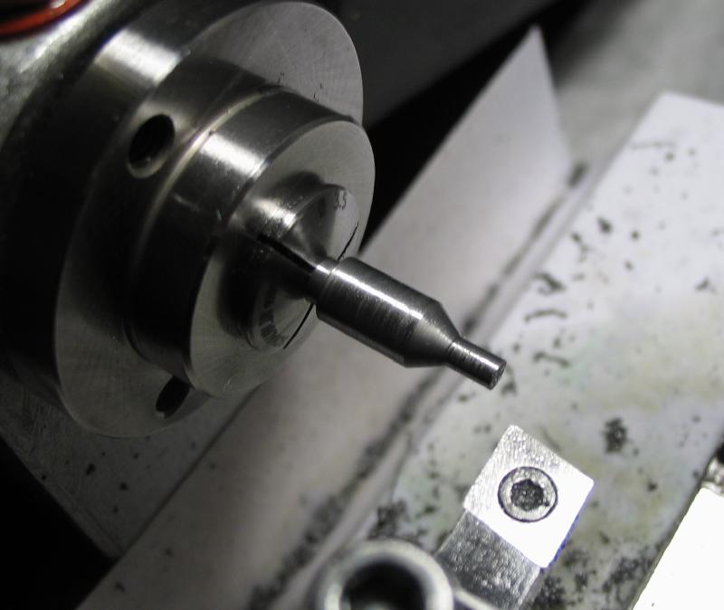
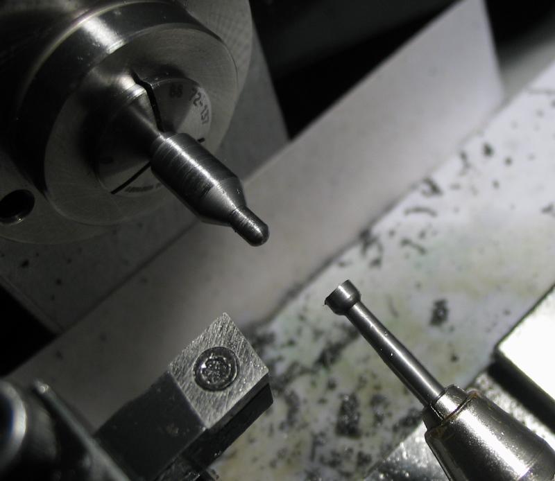
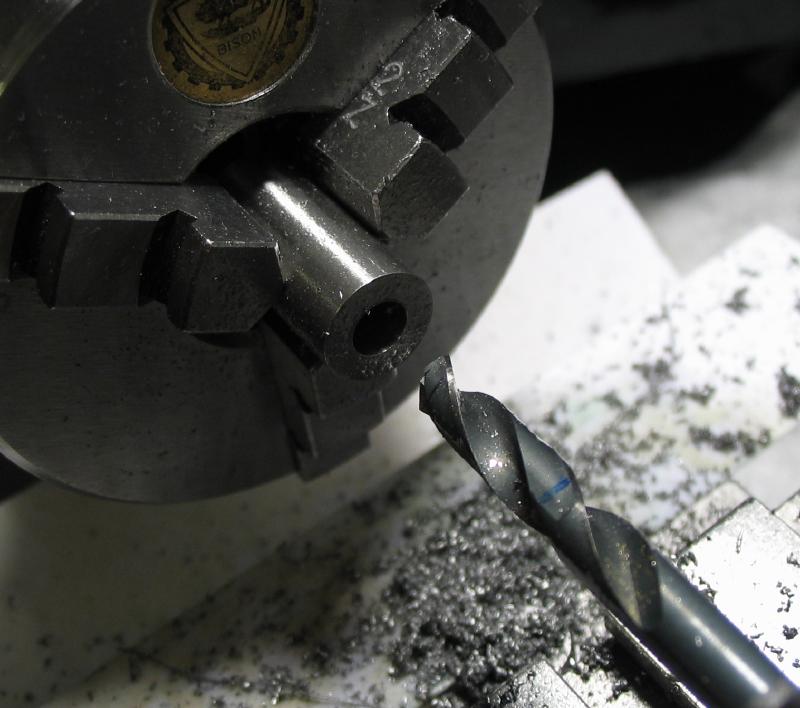
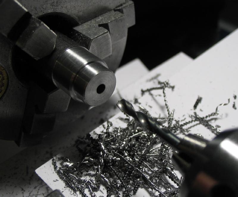
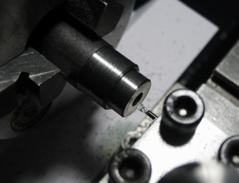
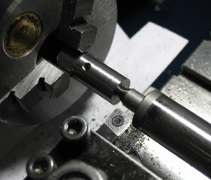
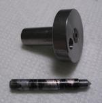
The detent was started from 8mm oil-hardening drill rod. It was center drilled and with tailstock support turned down to 4mm and the end reduced and threaded M3x0.5. The 4mm diameter was smoothed with an Arkansas stone. It was reversed into a collet and the head portion reduced to 7.5mm diameter.
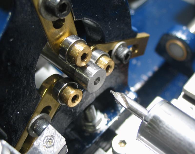
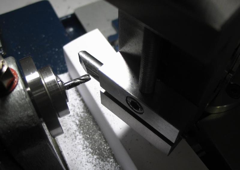
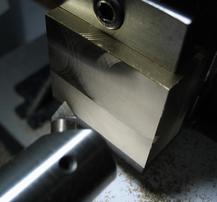
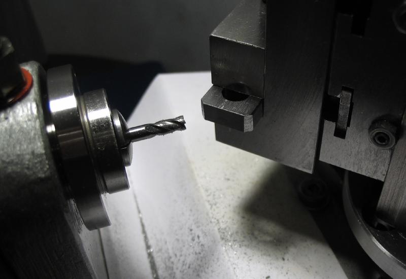
The vice and vertical slide were setup at an angle of 20 degrees and the tip of the detent milled and then repeated on the opposing side to leave a 40 degree wedge shape that fits into the tooth space of the spur gear.
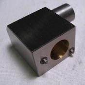
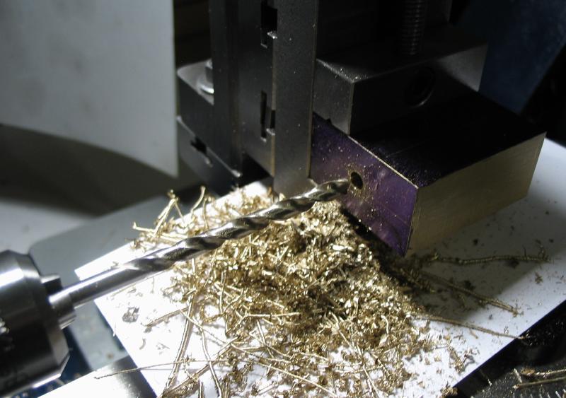
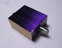
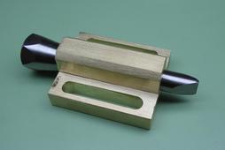
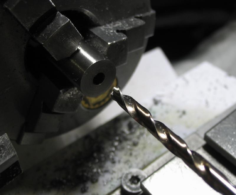
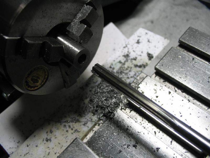
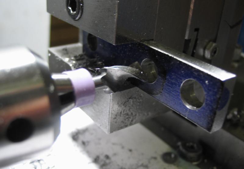
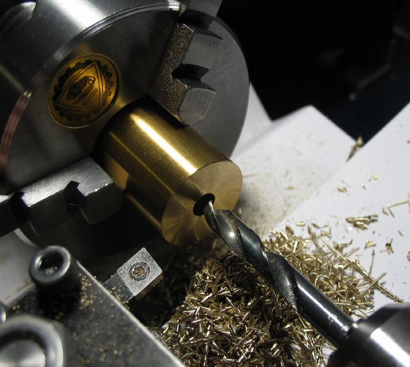
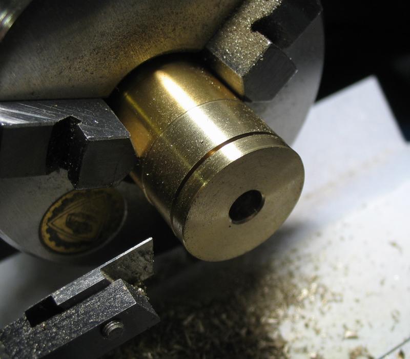
A length of brass bar (360 type) that is 5/8" x 1 1/4" was faced using a recently made flycutter, smoothed on 400 grit paper, and the final shape and location of the bore for the detent scribed out. A #25 (about 3.8mm) pilot hole was drilled through and then reamed 4mm. The hole was opened with a 5mm drill for a length of 23mm to admit a boring bit, which was used to open the hole for a slip fit with head of the detent.
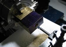
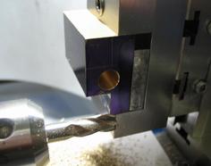
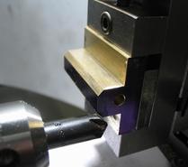
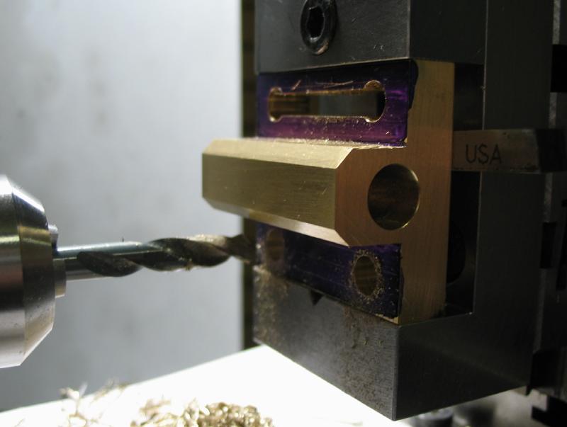
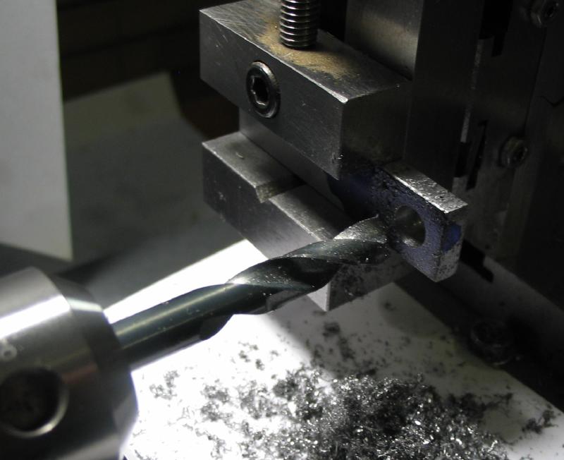
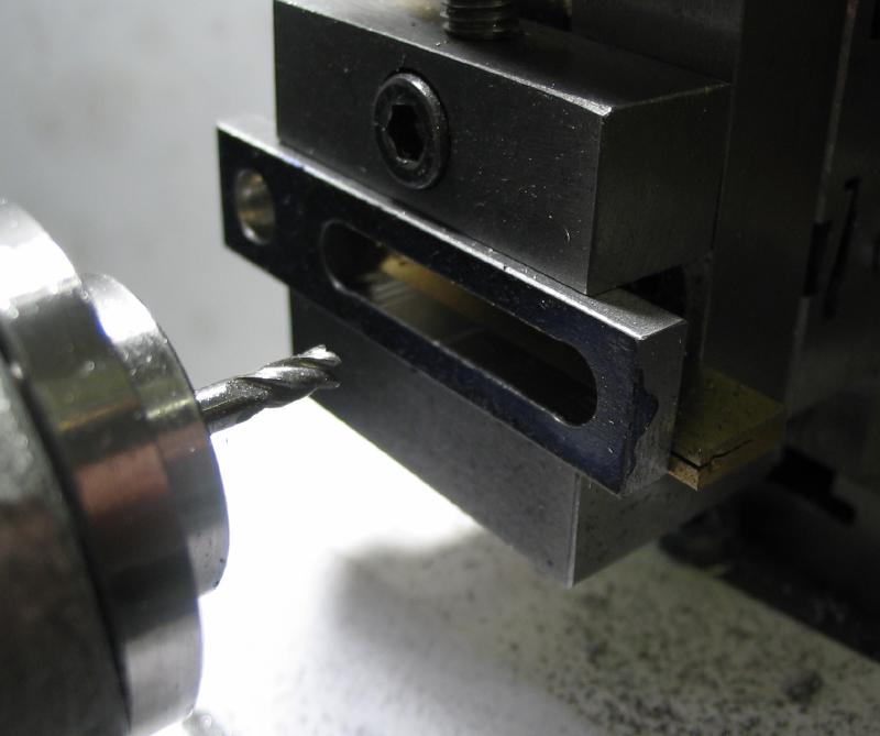
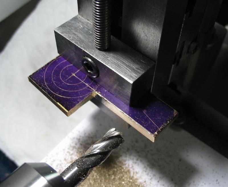
The block was mounted in the vise and some of the surplus thickness removed by milling. The top corners were relieved using a countersink bit as a sort of angled endmill. Slots for M5 screws were laid out and started by drilling 5mm at the extreme ends of the slot and connecting the holes with an endmill. The closest endmill on hand was 1/8", so the slots needed to be brought to size by filing. The filing machine attachment to the lathe was helpful for finishing up here and was its first real try out.
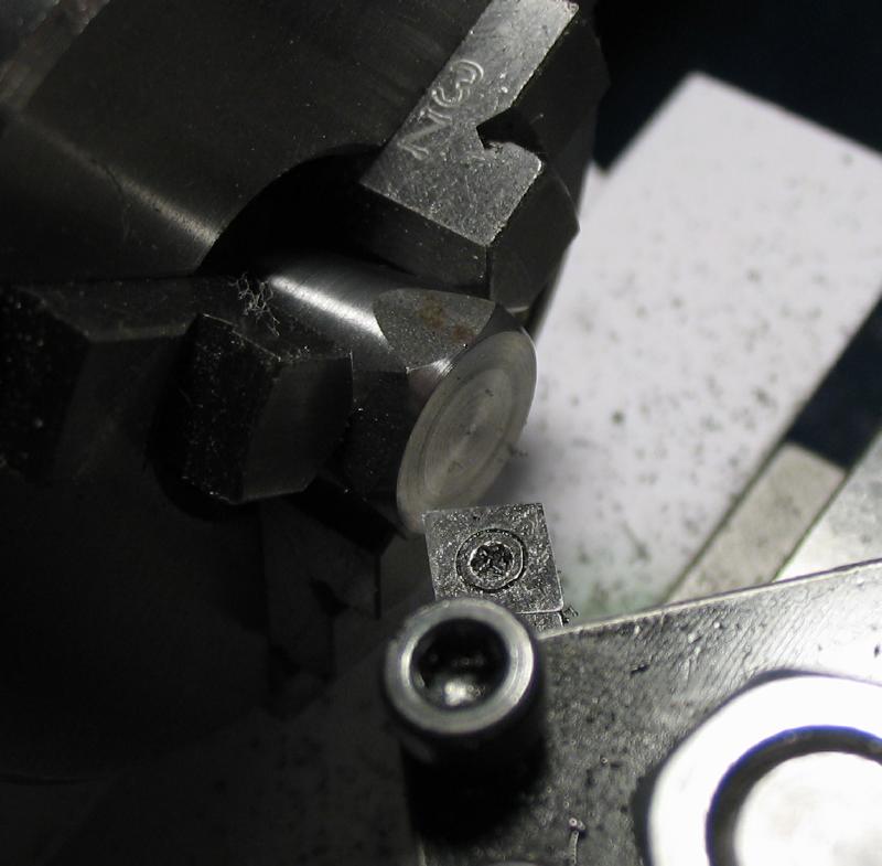
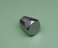
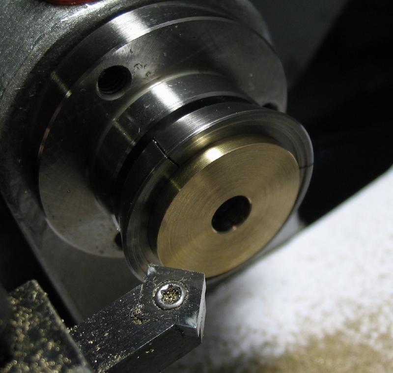
A retaining nut for the detent was made from 1/2" wide hex steel rod, primarily because there was a convenient length of it in the scrap box. It was drilled and tapped M3x0.5 and given a 10 degree taper, leaving the smallest diameter around 10mm. It was parted off and the reverse end faced and the sharp corners turned off with a 45 degree taper.
The detent is fit with compression spring that will provide its locking tension. The spring shown is about 1/4" in outside diameter, 3/16" inside, and 1" long, and the wire itself is about 0.6mm. These dimensions were not necessarily chosen, more so, it was a conveniently available size spring, however, its worth noting that the spring's dimensions influence many of the dimensions of the detent assembly.
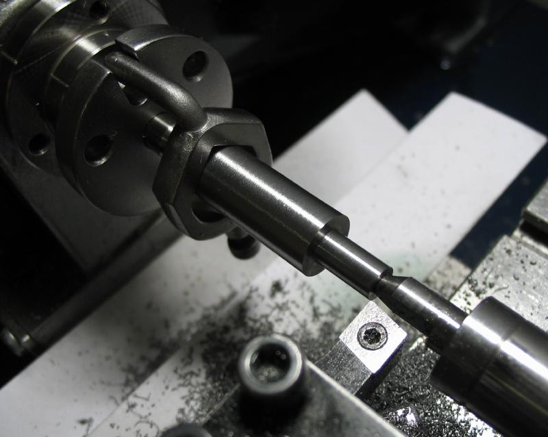
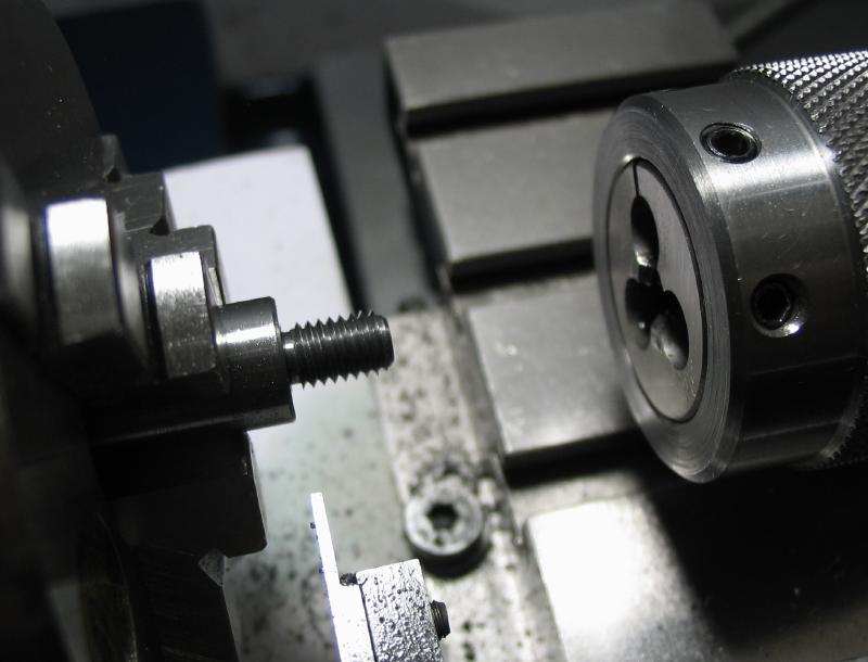
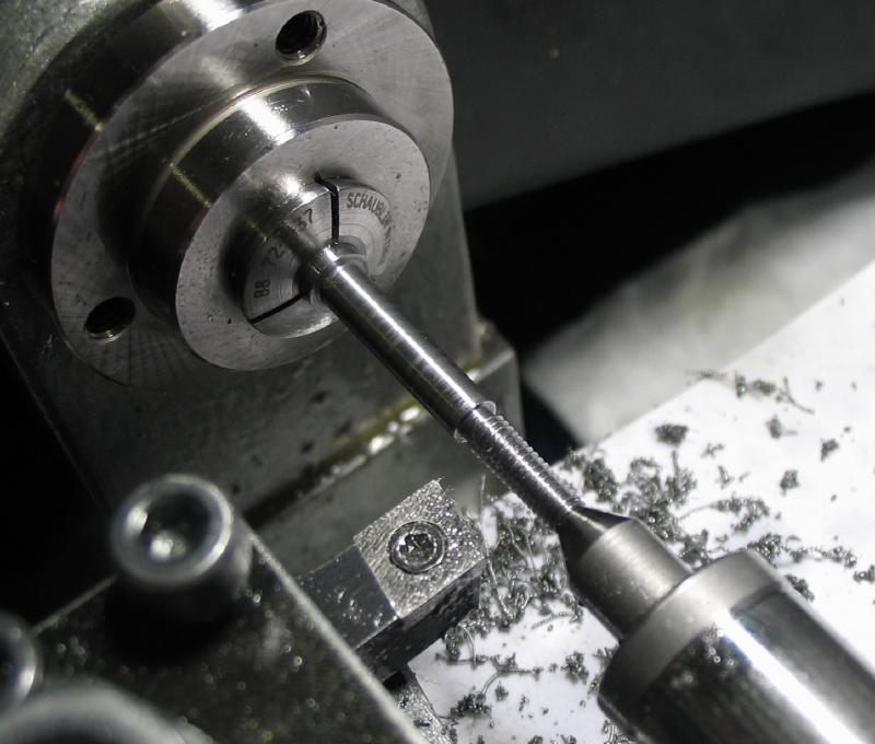
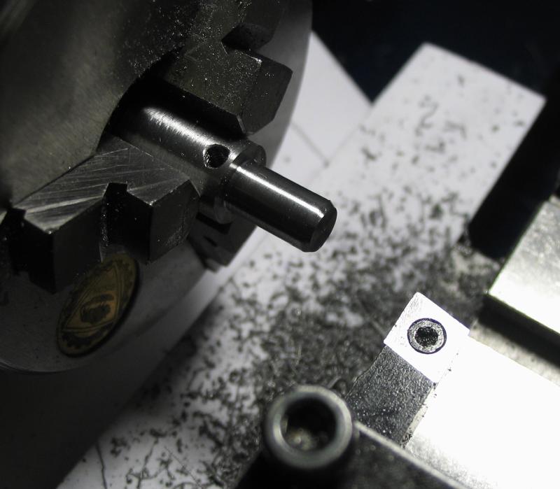
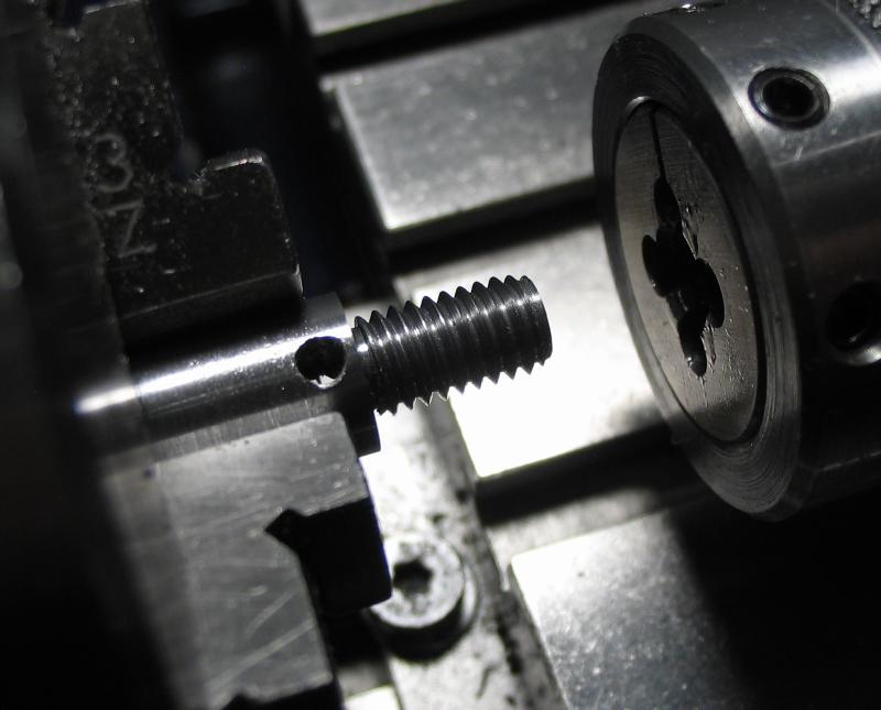
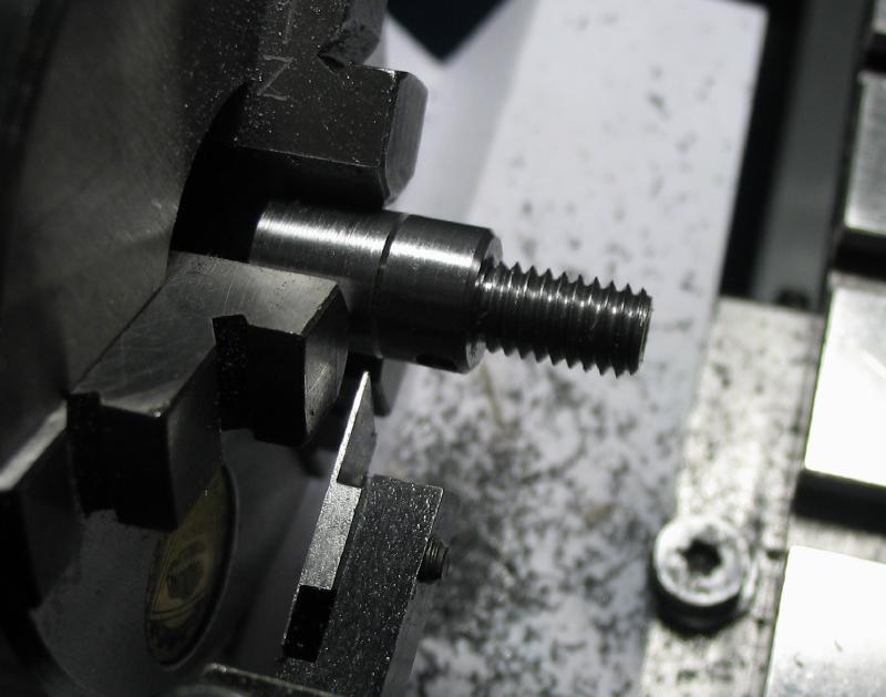
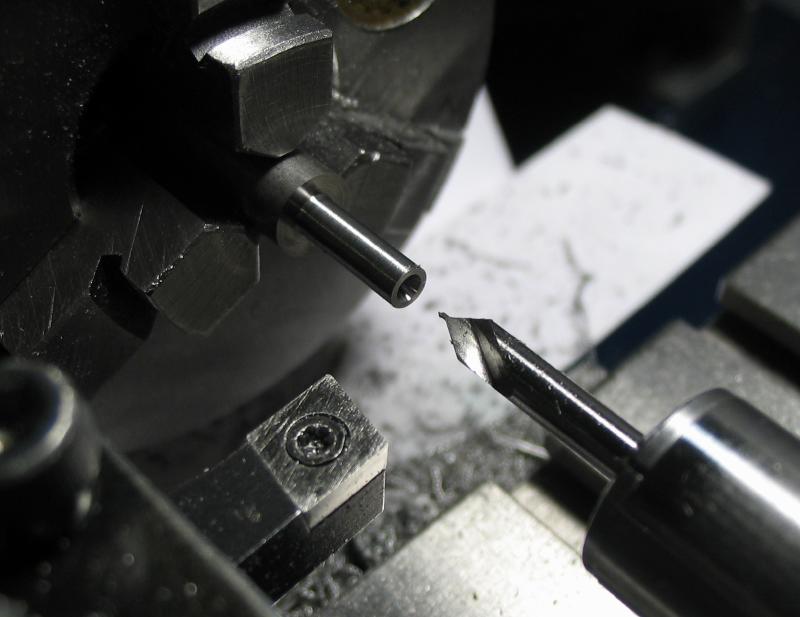
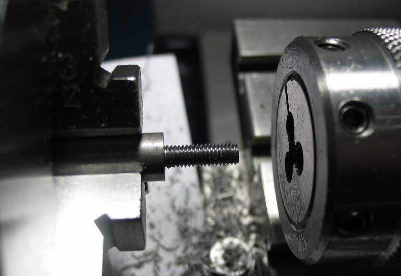
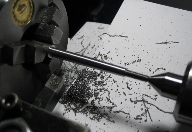
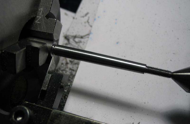
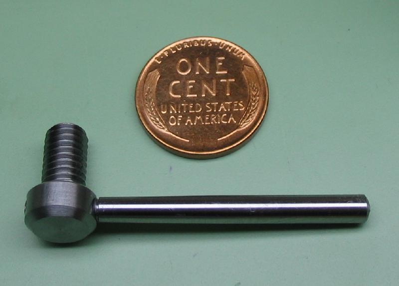
A stud for the spur gear was started from 1/2" steel rod (12L14). It was faced and center drilled on both ends and turned between centers. This will allow the work to be reversed for turning both ends and have a better chance of maintaining concentricity. Also, the rod needs to be a fairly snug fit to the bore of the gear, and holding between centers allows for the work to be removed, tried in the gear, and returned between centers for additional turning as needed. One end was reduced to 5mm for threading, however, without screwcutting ability, the threading step needed to be carried out using the 3-jaw chuck and a die. A parting tool was also used to turn slot next to the shoulder so that there is no unformed thread and ensure a good seating.
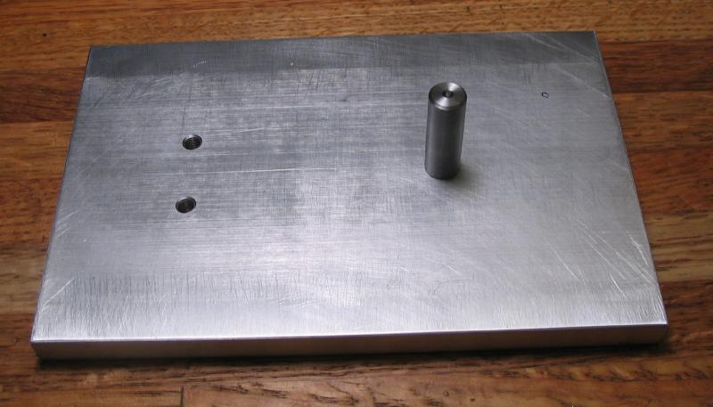
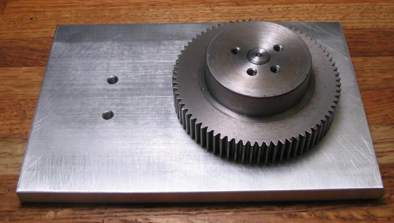
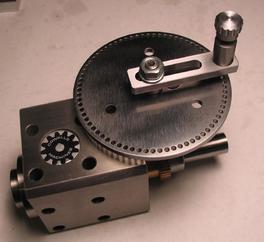
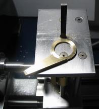
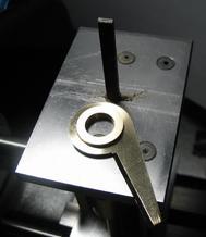
The base of the jig was made from a 6 inch length of 4" x 3/8" aluminum bar. The extruded bar is not completely flat, but too large to setup for machining, so a coarse file was used to at least smooth high spots. The surface was then rubbed with 400 grit paper on a sanding block to improve the general finish. A position on center and 2 inches from the end was drilled 4.2mm and tapped M5x0.8 for the gear stud. Locations for the detent assembly screws were drilled and tapped as well. The assembled jig is shown below, and one can see that a second set of tapped holes in the gear were made that provided better alignment with the division plate.
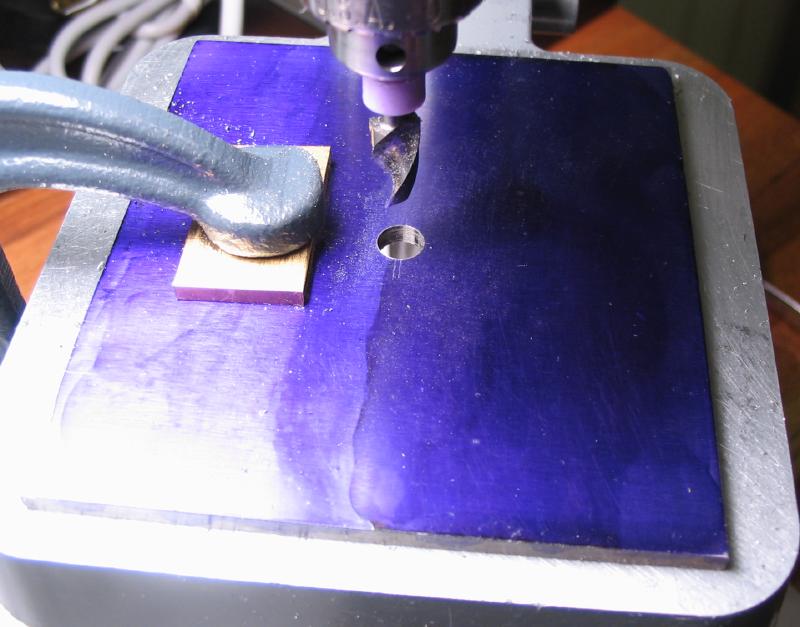
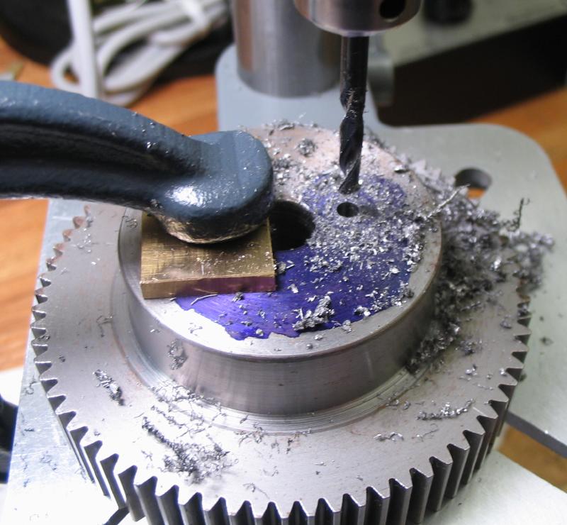
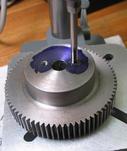
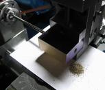
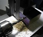
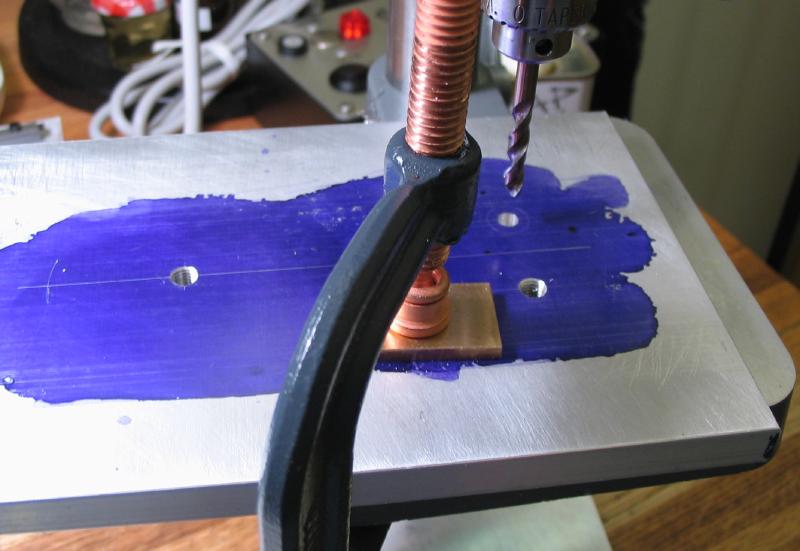
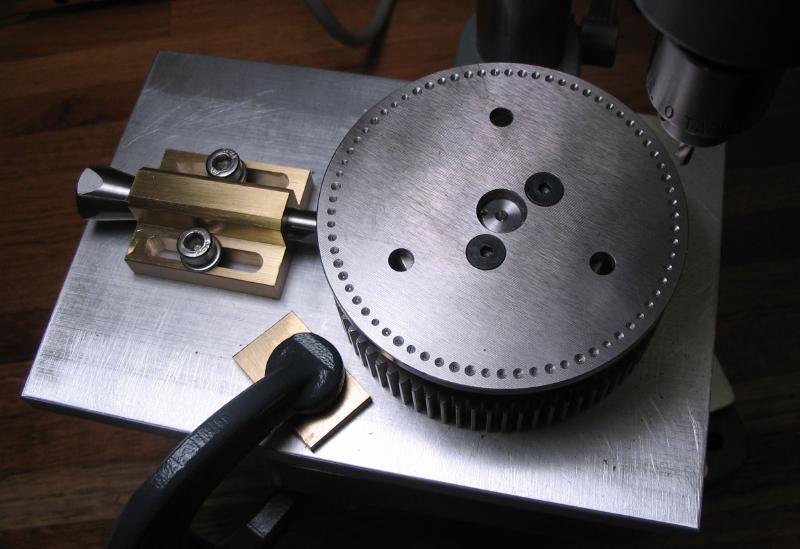
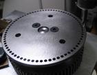
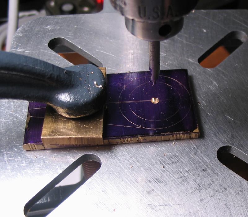
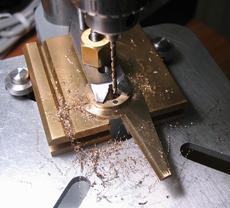
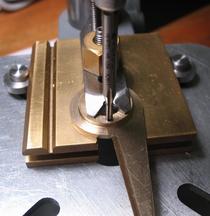
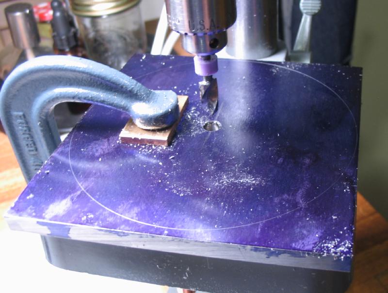
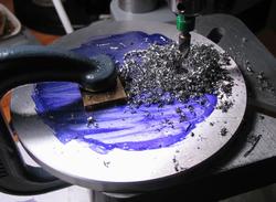
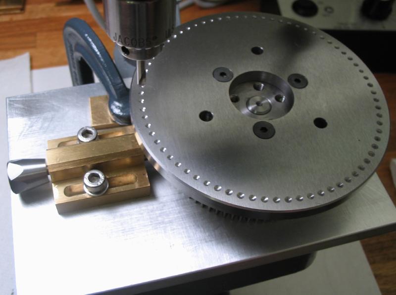
The jig was mounted on the drill press table and secured with a C-clamp after choosing a starting position, which was about 3mm from the edge. The 73 positions are provided by rotating the gear and locking on each tooth space. To avoid over two hundred tool changes, all the positions were spot drilled first, then drilled 2mm, and finally countersunk using a 60 degree center drill (only the countersink portion) and the drill press spindle stop set to provide a uniform finish.
After removing the plate from the setup, the holes were very lightly countersunk on the underside to remove burs. The surfaces of the plate were smoothed a little better than before on 400 grit paper taped to a glass sheet, and after cleaning up, it should be ready to put into service.
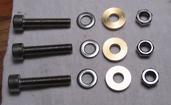
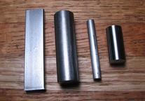
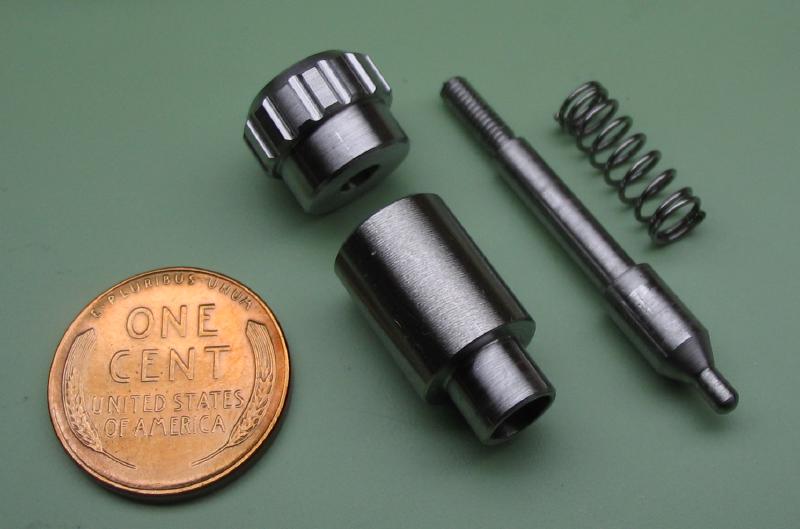
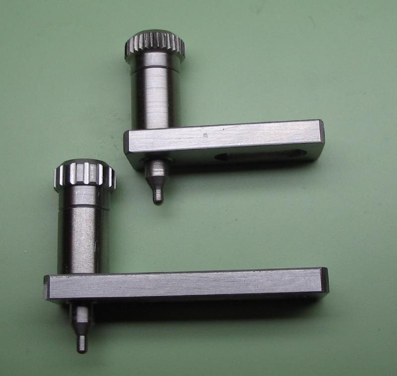
I am planning to basically reproduce the detent that was supplied with the dividing head, however, increase the length of the arm to accommodate the larger diameter plate. I happen to gather up the needed materials beforehand, and are shown below. The detent pin was started first, and is made from 5mm O1 drill rod. The rod was center drilled and the end turned for 9mm length (should have made this a little longer) and threaded M3x0.5. The rod was moved to a collet and with tailstock support, it was turned to 3.5mm diameter. It was then reversed into another collet, and the tip turned to slightly over 2mm (about 2.2mm), chamfered 30 degrees, and the tip rounded over with a cup bur.
The body was made from 10mm O1 drill rod, and was drilled through 3.3mm, reamed 3.5mm, and counterdrilled and reamed 5mm for about 15mm length. A length of 5mm was turned down to 6.5mm (plus about 0.02mm) and chamfered. The work was then reversed in the chuck and the top faced and chamfered as well.
The nut was made from 1/2" cold roll (12L14) steel rod. The rod was reduced to closer to 12mm diameter and the end turned down to 10mm, and corners chamfered. It was drilled and tapped M3, and in order to accommodate a little extra length of the detent shaft, the hole was counterbored open to 3.5mm for a couple millimeters.
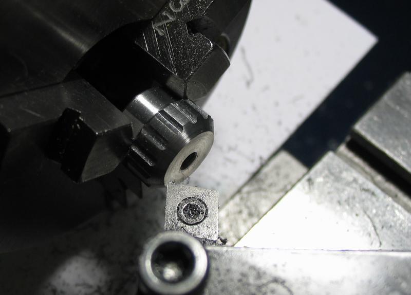
The milling spindle and a 1/16" ball end mill were used to form 15 grooves in the nut, and it was then parted off. The parted end was faced and given a generous 45 degree chamfer.
Shown are the detent components, which includes a compression spring that is 3/16" OD x 3/4" length.
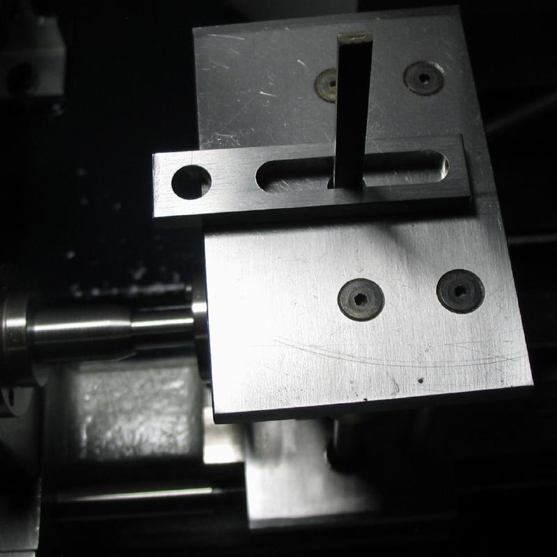
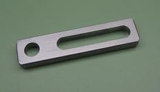
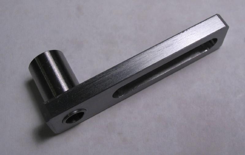
The detent arm was made from 3/16" x 1/2" cold roll steel bar. It was drilled 6.5mm and the end positions of a slot drilled 6mm. The holes were connected with an endmill and brought to final width with the filing machine. The slot didn't need this much room for adjustment, but it can be used for a wide range of diameters, should the need arise.
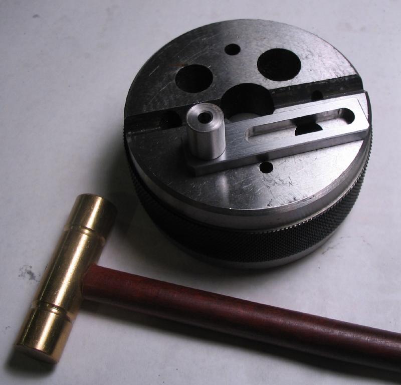
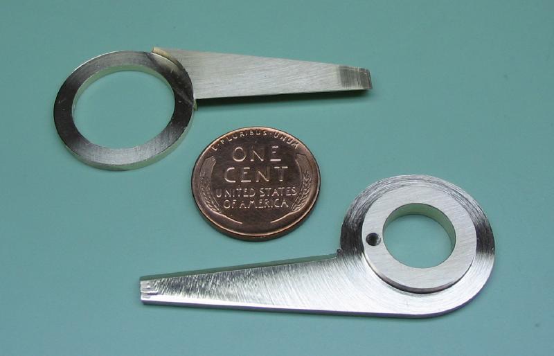
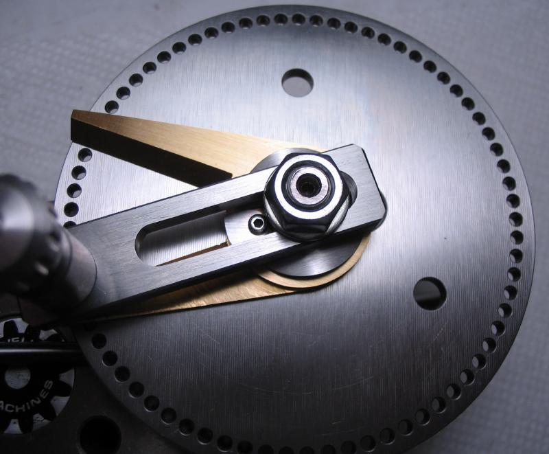
The detent body was inserted in the arm with the help of a small hammer, and is then ready to install on the dividing head. The assembled detent is shown next to the original one from Cowells for comparison.
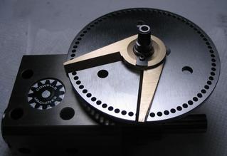
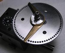
A "sector" device was constructed to assist in using the division plate. The Cowells dividing head did not include one, but there appears to be just enough space to fit such a contraption. A sector is commonly found on dividing heads and is simply a guide to indicate the next hole position. For example, to use the dividing plate made above to index 73 positions, the detent must be advanced 40 holes for each position due to the 40:1 worm gear. Even if one can count 40 holes, 72 times, without making a mistake, it would be a time-consuming endeavor. The sector can simply be set to a span of 40 holes, and thereby one only needs to count the required number of holes once.
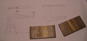
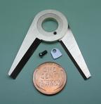
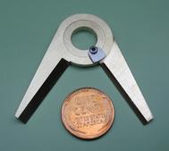
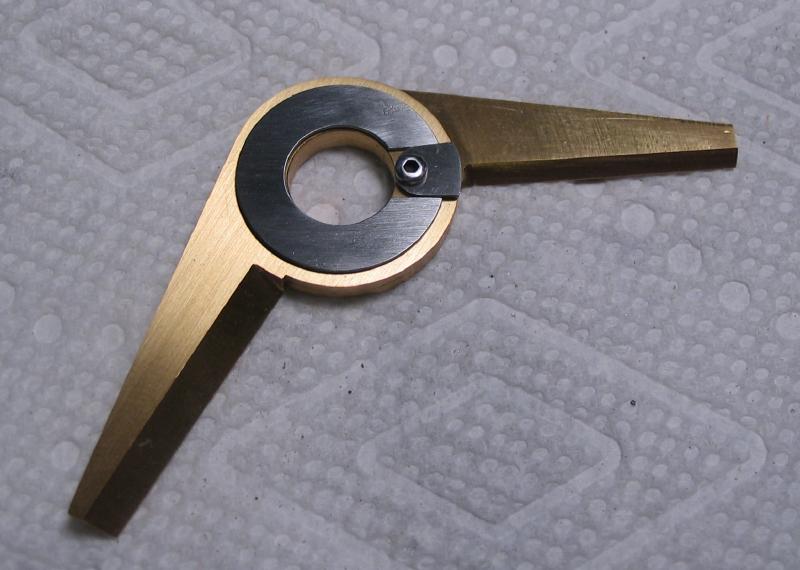
A sketch was started and I borrowed a design described on a webpage that details the construction of a dividing head for the Taig lathe. Two, roughly 1" lengths of 1/8" x 2" brass plate were sawed off that make up the two arms of the sector. The two pieces were advanced through the various steps at the same time, slowly bringing them to shape and, more importantly, to fit one-another. The sketches were repeated on the brass, and the upper piece center drilled and mounted on the lathe faceplate. It was drilled and bored open to 16mm and then counterbored to 22mm for a depth of 1.6mm.
The arms of both pieces were roughly sawed out and then milled to square things up. The arm area of the lower piece was fly-cut to reduce the thickness to about 1.6mm, and the center hole drilled 1/4" and the shape of the arm re-scribed. The edge on both arms were "sharpened" to a 45 degree shape by milling. Both pieces were then sawed out with a jeweler's saw.
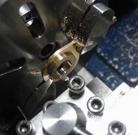
The lower piece was mounted on a 1/4" arbor to turn a boss 16mm in diameter and 1.6mm deep to fit the bore of the upper piece. It was then mounted on the faceplate to bore the hole open to 10mm to fit the dividing head arbor.
The general shape of both pieces was improved using the filing machine.
A position was found on the boss of the lower piece, drilled 1.6mm and tapped M2x0.4.
A 4mm long M2 button head screw is used, although the head needed to be turned down to 3mm to fit. An eccentric clamp-washer was made from a small piece of 1/32" steel plate by drilling a 2.05mm hole and sawing and filing to shape.
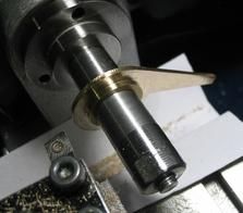
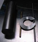
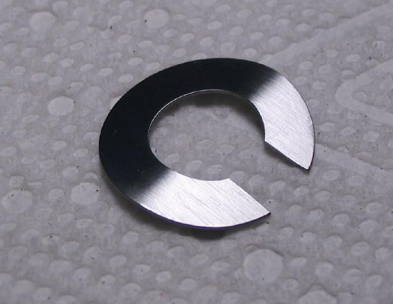
A spring washer was made intended for keeping the sector stationary while moving the detent. It was roughly sawed out from 1/64" thick oil hardening steel. A 1/4" hole was drilled and then used to hold the disc on the lathe to turn the disc true. It was moved to a step collet and the center hole bored open to a loose fit on the arbor of the dividing head (about 10.2mm).
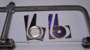
A slot was sawed out to fit the locking clamp. The washer was bent to fit the available space between the sector and the detent arm (about 1.5mm). The makeshift arrangement used to 'form' the bend is shown.
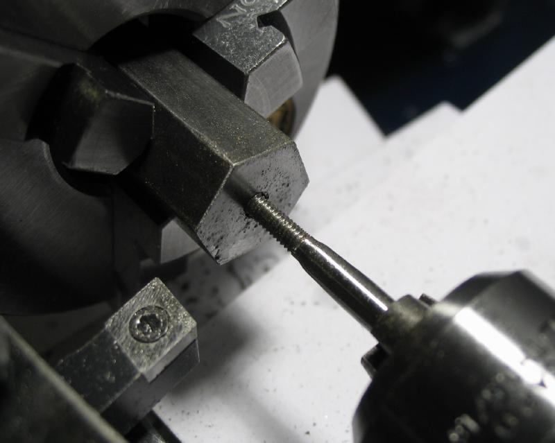
The increased diameter of the 73 hole plate prevents access to the set screw for locking the spindle of the dividing head. A special set screw with an extended handle was devised. It was started from a short length of 3/8" diameter cold roll steel rod (12L14). It was crossed drilled and tapped M3x0.5. The rod was moved to the lathe and turned true, reversed and a 10mm length turned down for threading M6x1.0. It was parted off slightly oversize and finished by turning and chamfering the parted face.
A handle was made from a 1/4" cold roll steel rod, although starting with 1/8" rod would have been better choice since it needed to be turned down that much anyway. The end was turned for threading M3x0.5 and center drilled for tailstock support. The length was turned with about 1 degree of taper and a plain diameter as needed until a good fit was found.
Another 73 count plate is described below that is intended for the lathe headstock. It is of different dimensions to fit the adapter to the Cowells headstock spindle and pin of the detent system. The plate can be smaller in diameter than the standard 6 inch plates, and I used the 72 count circle of the Cowells "G2" plate as a rough estimate. The plate was started from a freshly unwrapped and pristine half-yard of 1/4" x 4" oil-hardening O1 tool steel. It may be an indicator of a diseased mind to be so excited by such things. A roughly 4" piece was sawed off and the center ascertained and punched. A circle of 100mm was scribed and the center position drilled 1/4". The circumference of the plate was roughly cut out with a jewelers saw and being quarter-inch tool steel, this was somewhat of an ordeal.
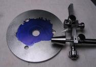
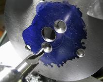
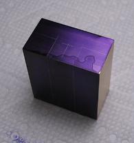
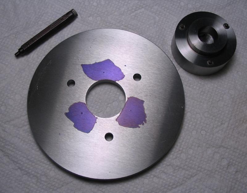
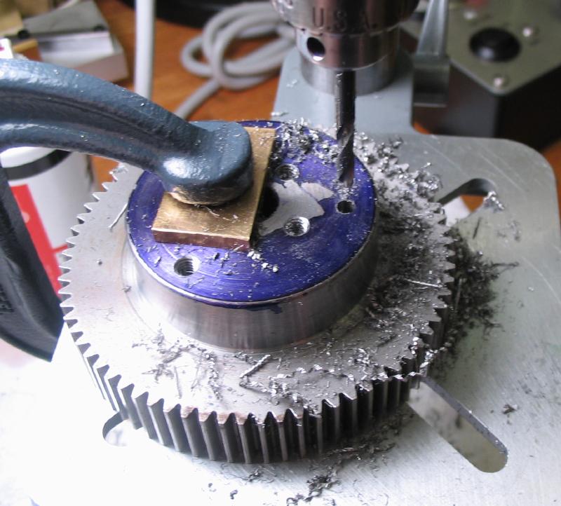
The plate was mounted on the Levin 1/4" arbor. After truing the diameter, it was a about 101mm. The rough surface was colored blue with a Sharpie pen to assist in easily finding unturned areas, although any interrupted cut is quite palpable while turning this relatively large diameter. Afterward, the corners were chamfered 45 degrees with the top slide.
Deviating slightly from the previous process used for the dividing head plate, drilling the three mounting holes for the lathe faceplate was carried out on the drill press. They were laid out by scribing a 25mm radius circle, choosing a point on it to center punch, and then walking the divider around the circle. These locations were then drilled 5mm. I chose 25mm somewhat arbitrarily, but discovered later than moving them a little further out would have been helpful.
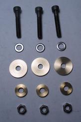
So that the boring bar can pass through the plate and not foul the lathe faceplate, a set of spacers were made to fit in between. The spacers were made from 3/4" brass rod that was drilled 5mm, turned true, the corners chamfered, and then parted off. The parted washers were held in a step collet and faced to the same cross slide reading so that they have the same thickness. The assembly was mounted on the lathe and centered with tailstock. This setup took full advantage of the gap in the lathe bed.
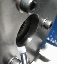
The center hole was bored open to 1 inch diameter, which will fit the headstock spindle adapter. The socket head screws prevent test fitting the adapter in the hole, so the boring was guided by dial caliper measurements and matched to the measured bore of a Cowells plate, which is spot-on 25.4mm (the diameter of the adapter measured 25.38mm).
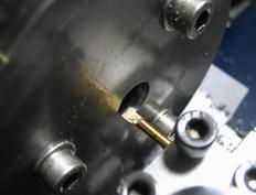
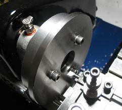
Transfer screws were installed into the headstock spindle adapter and the positions punched into the plate. These positions were drilled 4mm on the drill press, but since my countersink bit has a 1/4" shank, this step needed to be carried out on the lathe. A setup was fabricated using the vertical slide, dividing head, and faceplate. A slot of the faceplate was put on lathe center and the index plate blank fixed into place with one socket head screw (only one aligned with a slot), and a couple toolmaker's clamps were added for extra rigidity. The M4 countersink was used to ream and countersink the three holes to fit the screw heads.
The plate blank was test fit to the spindle adapter to be sure everything is aligned thus far.
I considered using the new dividing head plate to index the positions for making this one. This would be best carried out while it was still attached and centered on the lathe faceplate. Instead, the spur gear jig was utilized, which I liked the idea of getting a second use of it before being retired to a drawer. New screw positions were laid out, drilled and tapped to match the three countersunk screws. This was carried out on the drill press as before. After finishing one position the plate was attached and the next screw position punched or double-checked. A couple tools were made to help, a center punch, turned to fit the holes in the plate and a plug that consists of a 1" disc with a 3/8" pin set into the center. The disc was leftover from making the filing machine, and just needed a little boring to get running true and it was already machined for a countersunk screw. The pin fits in the bore of the spur gear and the disc used as a temporary mount for the plate to locate the screw positions.
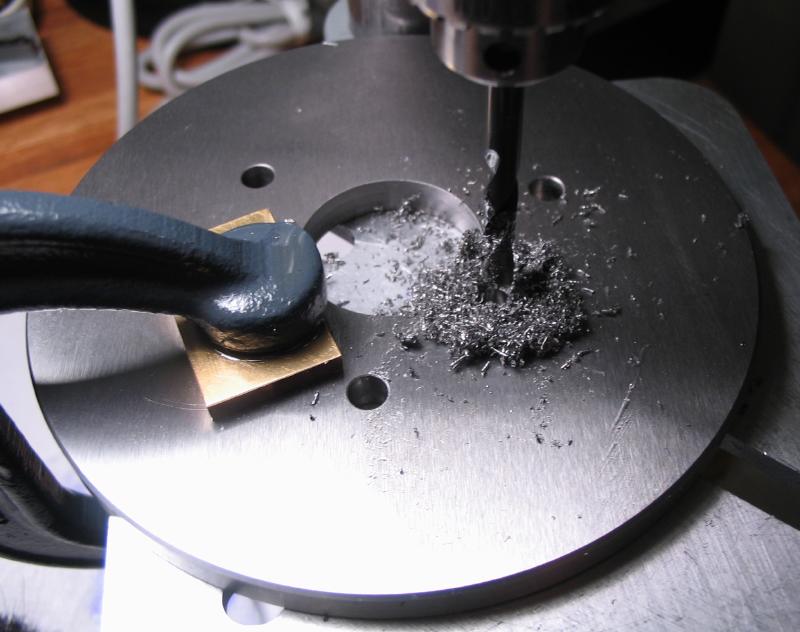
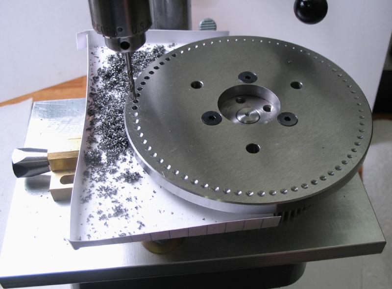
The plate was spot drilled for the 73 positions, drilled 3/32" to a depth of 4mm, and then countersunk with a 60 mill-drill bit to a short depth limited by the quill stop. The 3/32" hole does not need to go through the plate but only clear the tip of the detent pin, which is a blunt 60 degree point. A makeshift swarf tray was made from a paper card to help keep debris out of the gear teeth, which was a bit of a nuisance while drilling the plate for the dividing head described above.
The faces were rubbed on 800 grit paper to remove some of the minor scratches incurred in the steps above, and then after cleaning up, it should be ready for use.
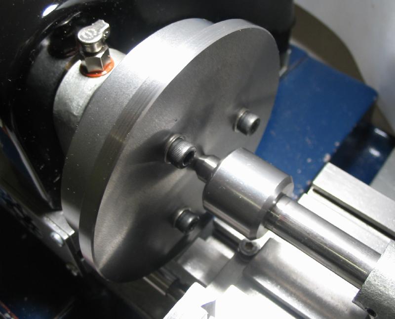
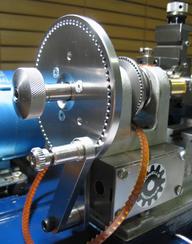
Mounted on the lathe headstock.
Comparison photo of the two 73 hole plates.
