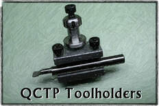
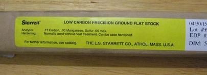
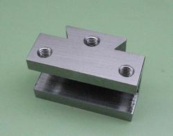
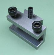
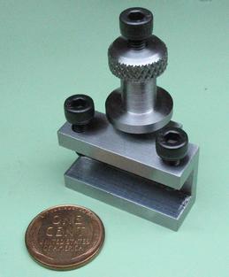
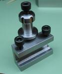
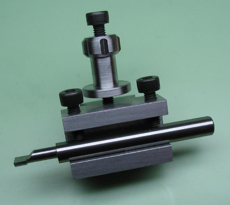
The prodcution of a batch of toolholders that fit the Cowells quick-change toolpost are described below. They were made as a batch of seven to since the initial machining steps were carried out at the same time. They were started from a 6" long bar of 1018 mild steel. The finished toolholders have a width and thickness of 1-1/4" x 5/8". This can be machined, of course, but the dimensions are not critical, so instead I am starting with ground steel that is supplied in these two dimensions. The Starrett precision ground steel is more expensive than regular cold roll 1018 steel, but the latter would require the next largest size of stock since the faces would need to be milled to these dimensions, which is extra work and waste/tool wear. The Starrett steel is sold in 2 foot lengths, which could make about 28 (or so) toolholders, if so inclined.
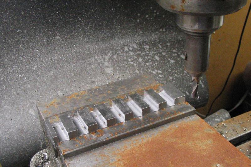
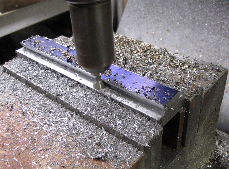
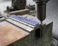
A six inch length of the Starrett steel bar was sawed off and mounted on a Bridgeport milling machine; the vise jaws are six inches wide, so this was a convenient size stock to work with. The bar is rested on parallels to raise the height for milling the tool slots. The sawn edge was faced with the side of the endmill, and the slots milled with a 3/8", 2 flute endmill to a depth of 5/16". I left about 0.06" of extra space for sawing off between each toololder, but initially intended to add more, so there is some extra waste on the opposite end of the bar.
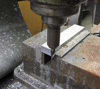
The bar is flipped over and the same endmill was used to mill the dovetail width, removing about 1/4" on each side (not shown). The endmill is exchanged with a 3/8" 60 degree dovetail cutter and the dovetail milled in several passes. Both of these milling steps were preformed using the variable speed power feed option on this mill's main slide. It makes for less manual labor and a more uniform finish, and left with nothing to do except watch, I was able to snap a photo in action.
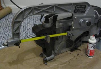
The individual toolholders were then sawed off using the Hand-I-Hack.
The sawn faces need to be face milled to make them flat. Milling with a 1/8" endmill is definitely the long way to go about it...
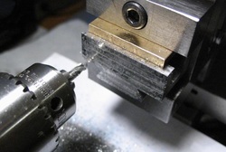
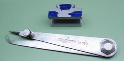
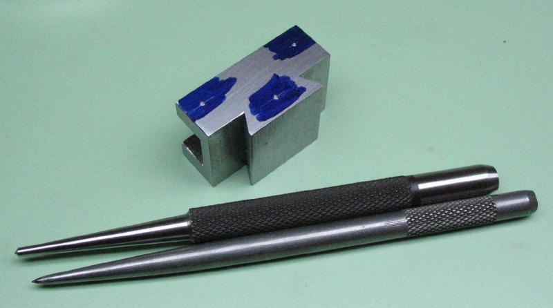
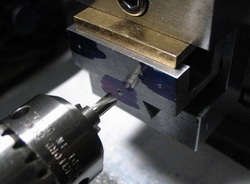
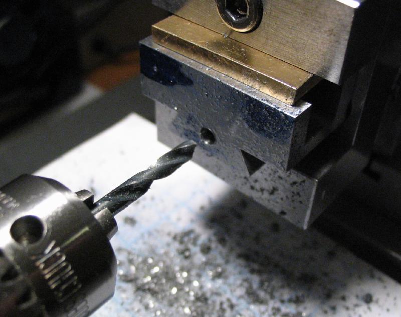
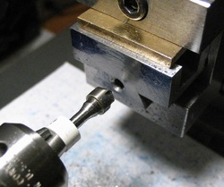
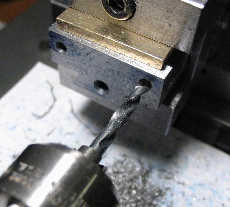
Tooling marks and burs around almost all the edges were removed (at least for the most part...) by filing and rubbing on 400 grit emery paper. The positions for the screws were laid out with a jenny leg divider, set to about 5/32", and then found with a center punch. The holder was returned to the machine vise and the positions located and spot drilled, drilled 3.3mm, and countersunk to help start the tap. The hole for the height adjuster set screw was drilled to a depth of about 12mm.
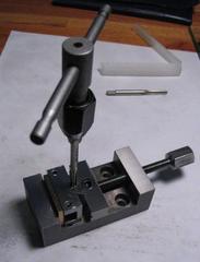
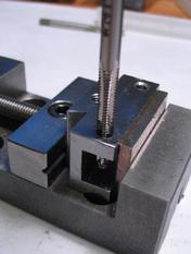
The holes were then tapped M4x0.7. The set screw hole was tapped to depth of about 8mm or checking with the set screw so that about 8mm is still protruding when tightened. The tool clamping screw holes are tapped through, of course.
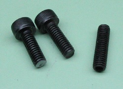
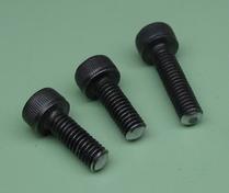
A stock set screw in M4x0.7 and 16mm length and two M4 socket head screws in 12mm length are used as the hardware. The screws tend to have a lip of metal on the end that makes the end uneven. The screws will be clamping down onto the lathe tool on their ends, so an even surface is preferred.
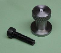
The height adjustment thimble was made from 5/8" mild steel (12L14). I had access to a Monarch 10EE while making the first couple of these, which makes the turning steps go much more quickly and can easily hold a 5/8" diameter rod in a collet whereas a short cut-off would have to be used on the Cowells in a 3-jaw chuck.
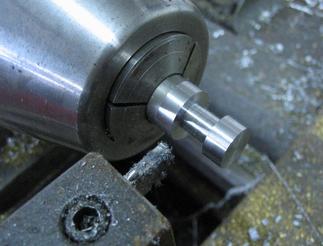
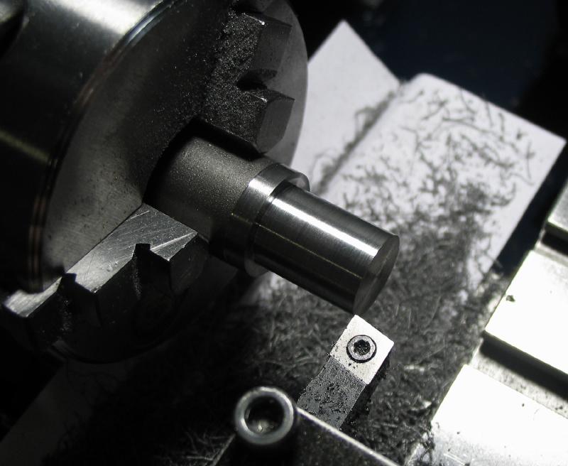
The rod was faced and turned true and then turned down to 0.5".
A waisted portion was formed using a parting tool, leaving about 0.25" for the grip portion of the thimble.
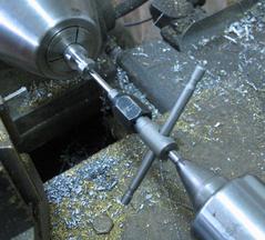
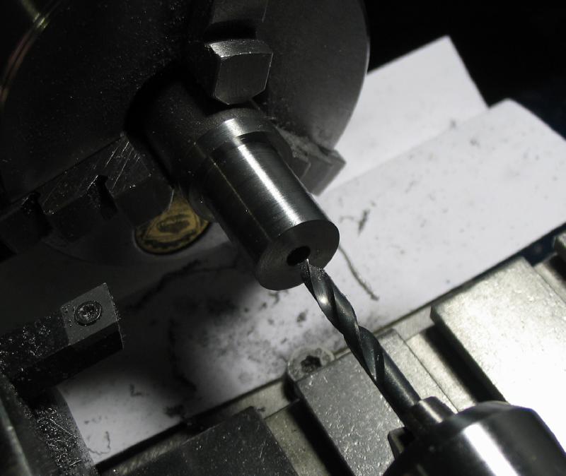
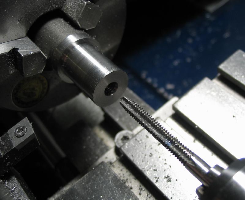
The rod was drilled 3.3mm and then tapped M4x0.7.
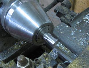
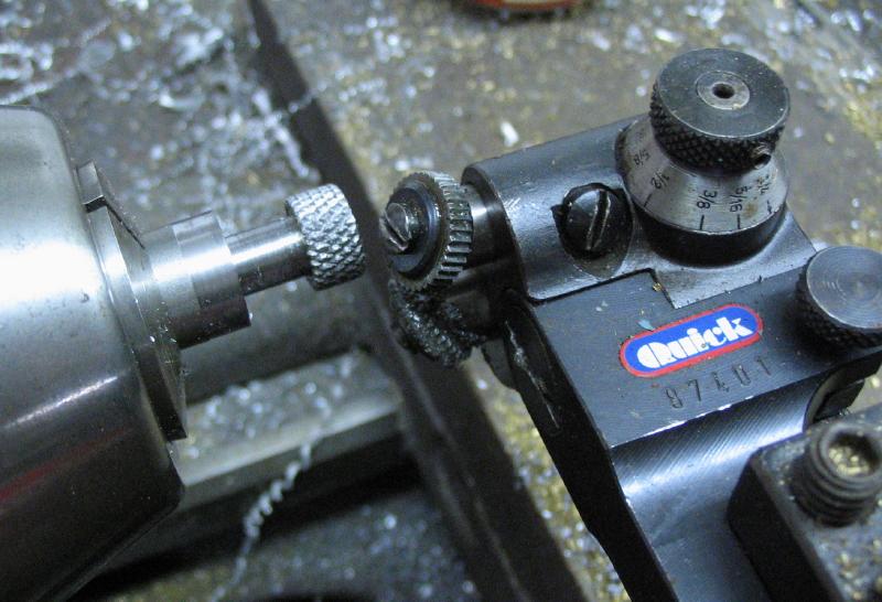
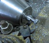
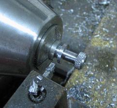
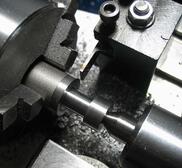
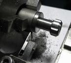
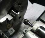
The grip portion of the thimble was then knurled using a Quick brand cutting knurler. Below is the first attempt at using the tool, which was not too bad, but the tool likely needs some adjustment to improve the finish. The corners were chamfered using the compound slide set to 45 degrees.
The thimble could then be parted off.
The last piece of hardware is a M4 socket head screw (16mm length) that fits into the thimble and acts as the locking screw.
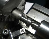
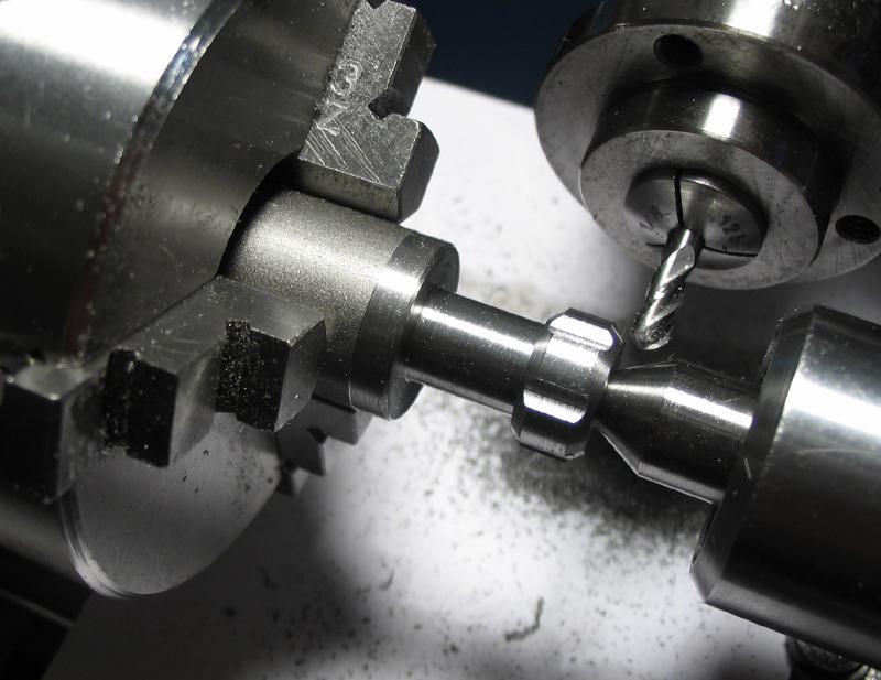
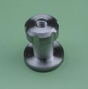
The basic process was used for producing a height adjustment thimble using the Cowells lathe, however, milled grooves were used in place of a knurl.
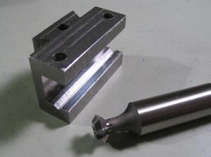
A couple of the tool holders were given a groove with a 90 degree double angle cutter. These are useful for holding round shank tool bits, such as boring bars.
