The Balance Wheel
I will be making a Daniels style four armed monometallic balance wheel. It uses eccentric gold weights for isochronal adjustment.
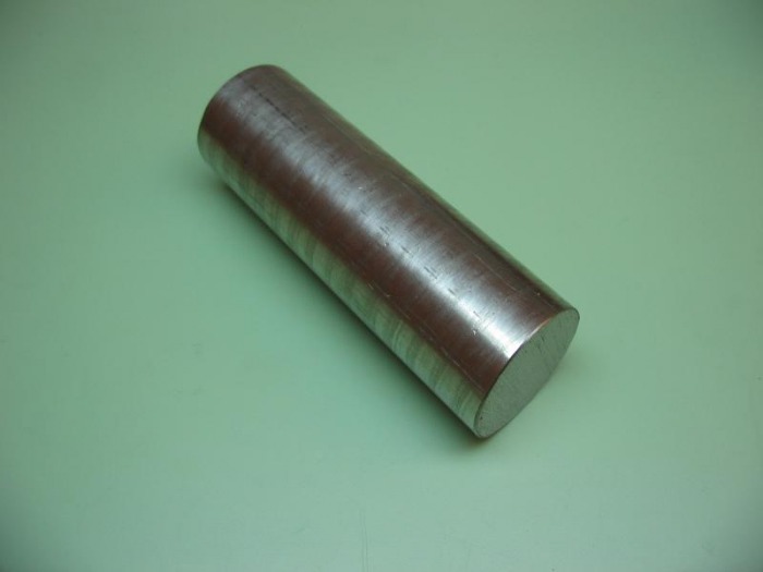
Daniels uses stainless steel for his balances. He doesn't specify a particular alloy, only that it be preferrably "free cutting and non-magnetic". I chose, as a matter of convenience and some choice, the starting material as a piece of 1 inch stainless steel round bar Type 303 (ASTM-A582), which is a free-machining alloy.
I drew the balance in AutoCAD, however, I was not completely satisfied with it and I was experimenting with a another piece of software, TurboCAD. It is fairly similar, each program has its advantages and disadvantages. In some ways TurboCAD is a little more user-friendly, however, for frequently used commands it can be slower to use. For example, AutoCAD allows typed in commands, which is a timesaver (at least for me), as far as I could tell TurboCAD does not. In any event, the dimensioned drawing can be found below, and since I convert them to PDF for the site, the reader will likely not know the difference.
| Balance |
I begin by hacksawing a more usable section of the steel and I am reminded that I really need a cutoff saw...
The length of the steel is mounted in the 3-jaw chuck and faced on both ends. I am using carbide tooling for all operations.
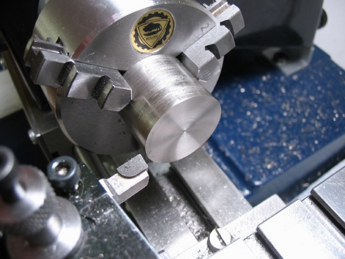
The rod is turned to full diameter (23.4mm) with the right hand carbide toolbit.
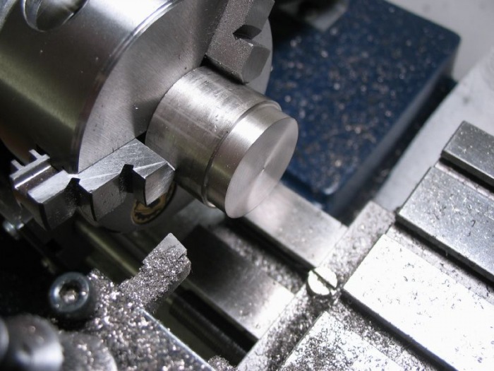
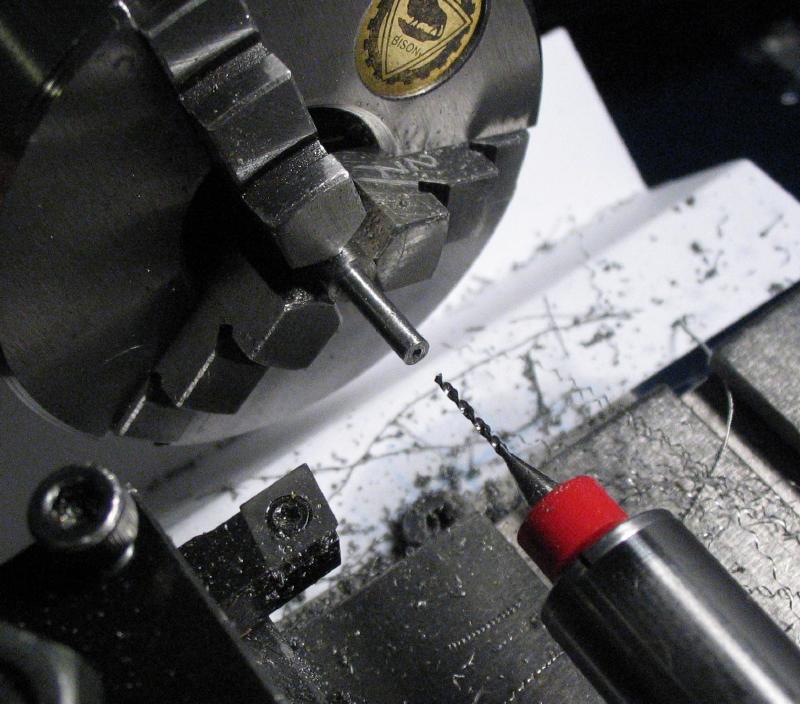
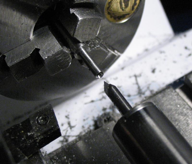
Next, I decided to center drill and drill undersize (a carbide 3/64th" drill to clear the 0.045" boring tool). Daniels shows boring the recess prior to forming the hole, however, I generally find that having a center hole makes boring a bit easier.
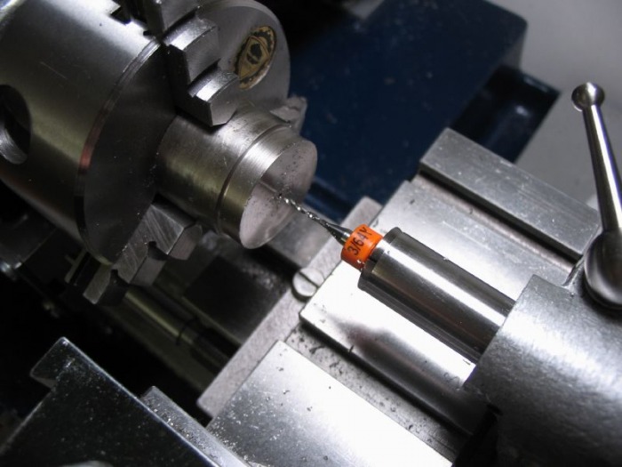
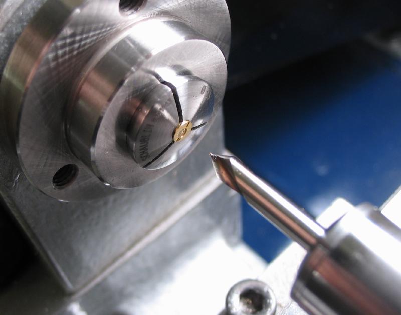
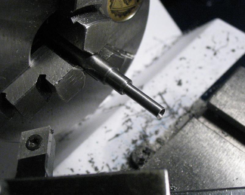
The hole is bored to 1.5mm with a micro carbide boring bit.

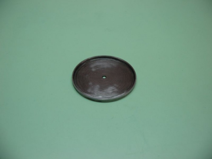
The recess in the balance is then bored out with a carbide boring bar to a depth of 0.95mm and 22.5mm in diameter.
The balance is then parted off, about 1mm oversized. The extra width is to prevent distortion from the cutting pressure of the parting tool. Parting can be a stressful operation (to the lathe and the operator), and parting stainless steel doesn't make it any easier.

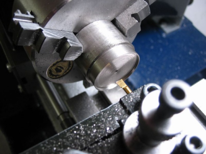
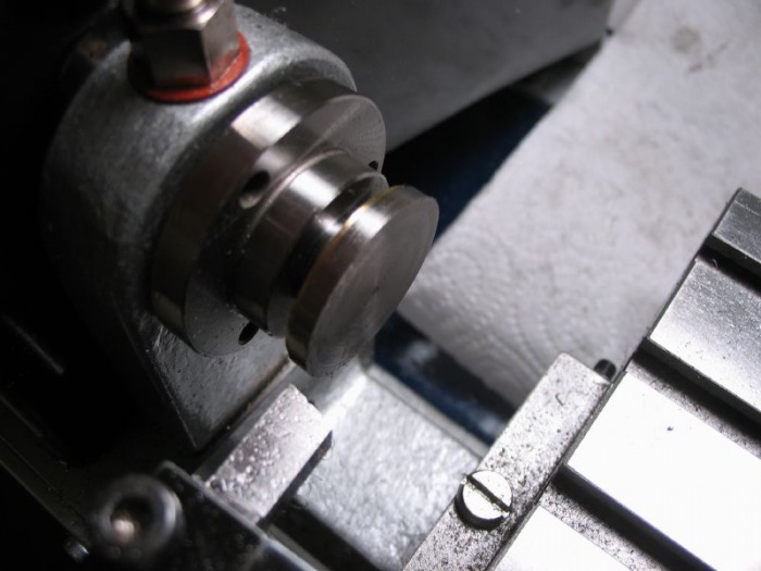
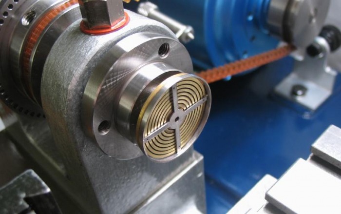
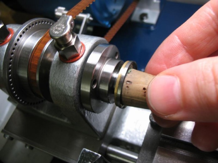
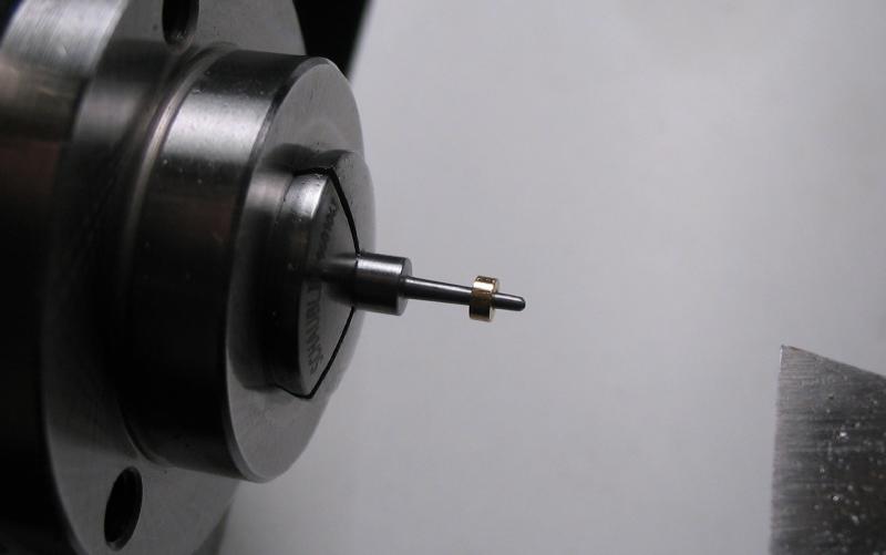
With the parted balance, Daniels recommends reversing it and friction fitting it onto the faced end of the remaining bar. Not having much success with that method, I machined a brass superglue chuck with a taper (~1 to 2 degrees) to give a friction fit with the balance wheel. This worked for several passes of the facing tool, and then I settled on adding a smear of super glue to the arbor. The balance was then faced down to the final thickness of 0.45mm.
The super glue arbor, after modification.

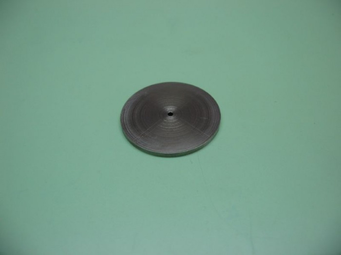
The balance in place and most of the facing complete.
Facing complete and still attached to the arbor.
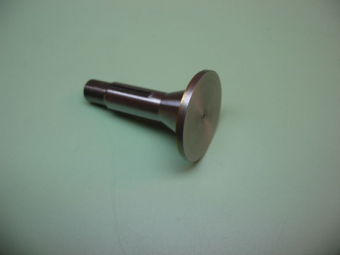
With the balance in this position, the hub and arms can be crossed out with the toolpost and cross slide, the position for the timing weight posts can be scribed as well.
 |
 |
It is then drilled, sawn, and filed to shape.
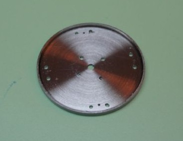
The filing is carried out by holding the balance in an adjustable vise with nylon jaws. A half-moon shaped piece of brass was made to fit inside the rim of balance to distribute the pressure of the vise jaws off of the balance rim. Filing was done with No.2 files for coarse removal and then with No.6 escapement files with safety edges for getting into the corners.
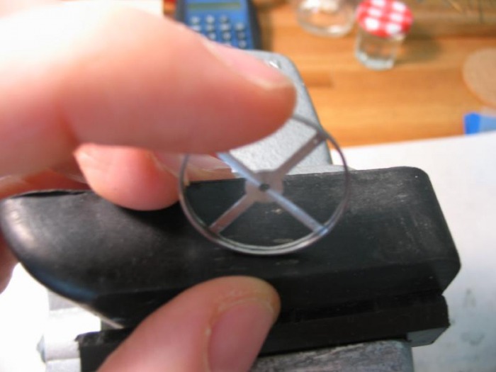
The inside rim of the balance was filed while holding the balance against a rubber block.
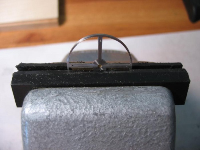
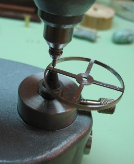
The filing must be carried out very carefully, not only for aesthics, but the poise of the balance must be maintained, this is accomplished by frequent examination for poise and subsequent filing to correct it. Ideally, the poising table should be used for examination of the poise. However, not yet being fit with a staff, I needed another method. Curiously, Daniels states that the poise must be repeately checked but does not specify how this is to be carried out at this stage. I tried a few ideas for a temporary staff/arbor and thought I devised my own system, however, paging through 'Watchmaking' I seen a very similar system described for polishing ratchet wheel teeth (Figure 81 - "Centering arbor for loose wheels" in Chapter 3 - Finishing Brass and Steel). So it must have been ingrained into my subconscious...
The balance is secured to the arbor and mounted in the truing caliper. If the tension on caliper is made lightly, the balance will be free to rotate, finding its own relaxed position. I was concerned that the arbor may have its own poise errors, and more experimentation is in order, but marking the top point on the balance and then rotating the balance on the arbor and retesting, the balance finds the same position after coming to rest. So least for the purpose of filing the balance to shape, I think this method is viable. It will certainly not be the last time the poise is tested!
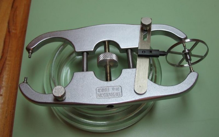
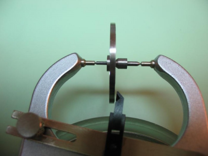
Bergeon No. 1883 Truing Caliper
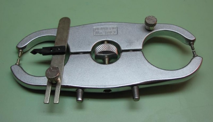
| Bergeon No. 1883 |
 |
 |
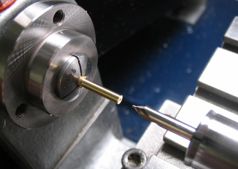
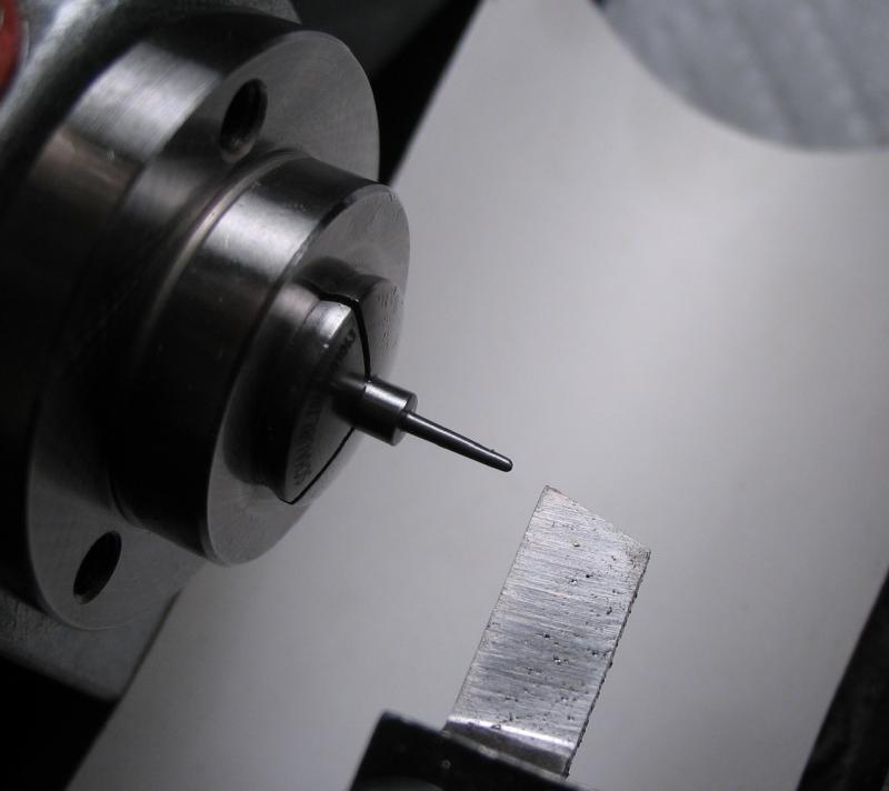
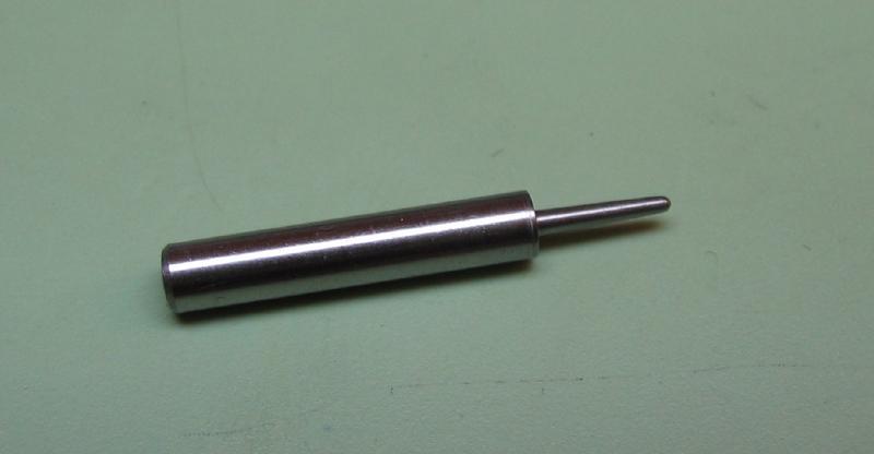
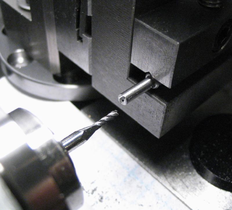
Posts are turned by hand from blued pivot steel for attaching the eccentric weights. The posts have a 0.9mm base and a 0.4mm tapered fit to the holes drilled in the balance arms. I used a Waller carbide graver and the Cowells T-rest attachment.

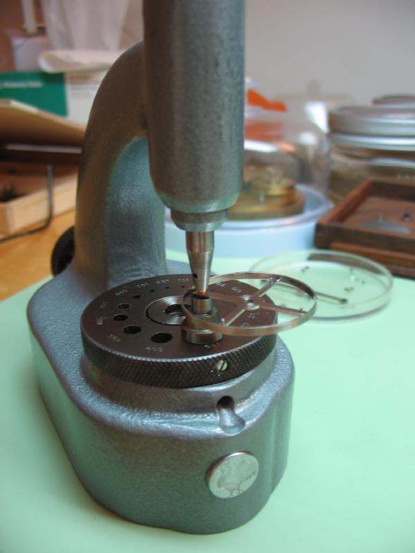
These are then driven into position on the staking tool.
Gold Adjusting Weights
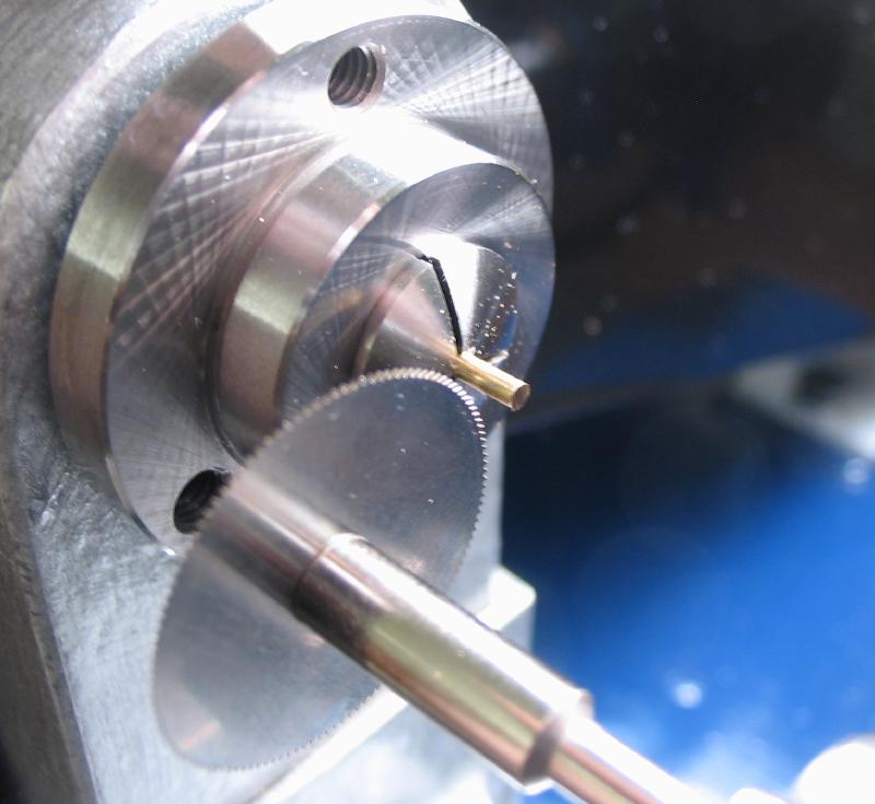
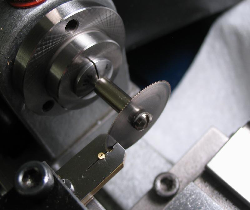
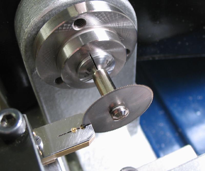
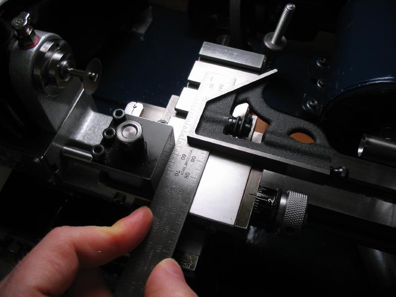
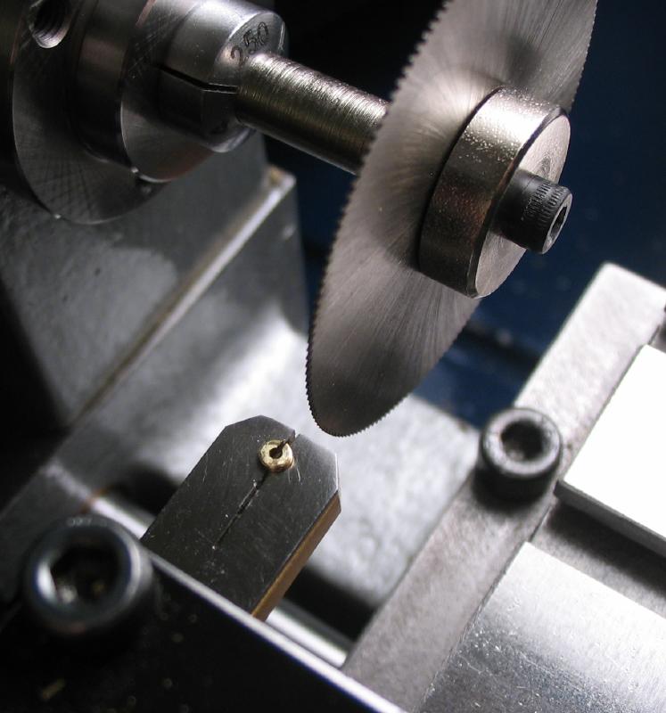
Discs of 0.75mm in height are sawn off using a small jewelers saw mounted in the toolpost and using the Foredom clamp. That way the cross slide can be used to advance the saw in steps of 0.75mm plus the saw width (0.1mm) and make a straight cut.

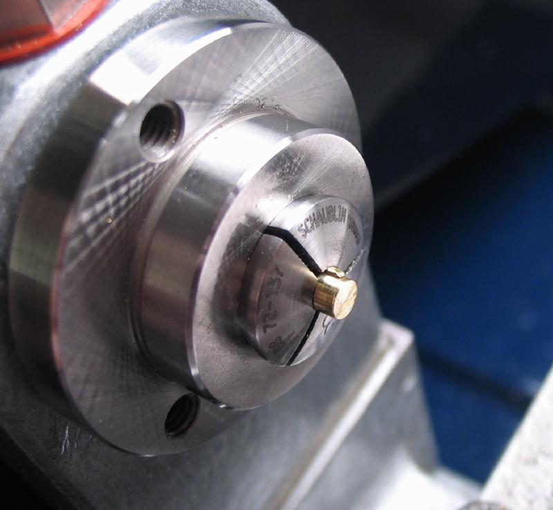
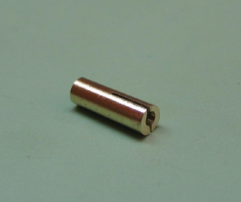
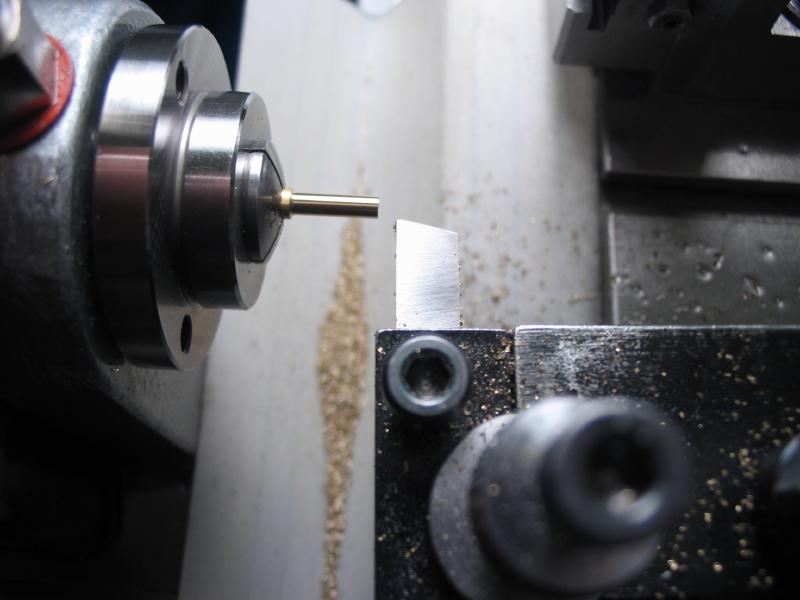
The discs need to be held eccentrically in the lathe for drilling the off-center hole. This is done with a small holding jig. A piece of 1/8" brass rod is turned down to 3mm.

The parted off piece of rod is held in a 3.3mm collet with a small brass shim to fill the space.
 |
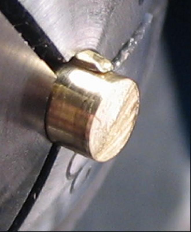 |
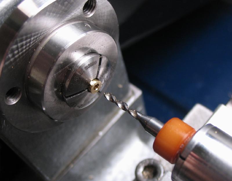
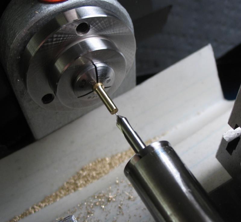
It can be then drilled 1.5mm (for the gold discs). The resulting hole will be off center.
 |
 |
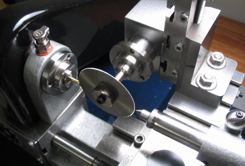
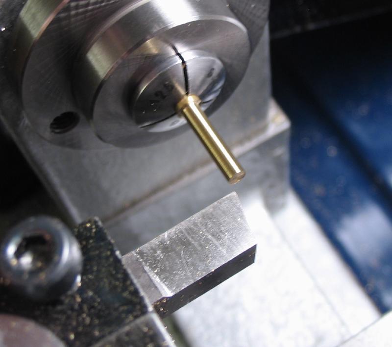
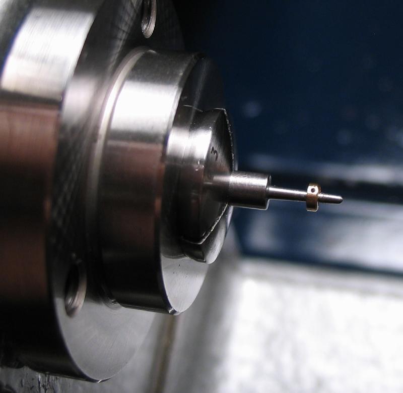
The rod is then mounted into a 3mm collet and positioned for sawing a slot. This will make the rod into a usable clamp. The rod is sawn using the milling spindle and a 0.006" Malco slitting saw.
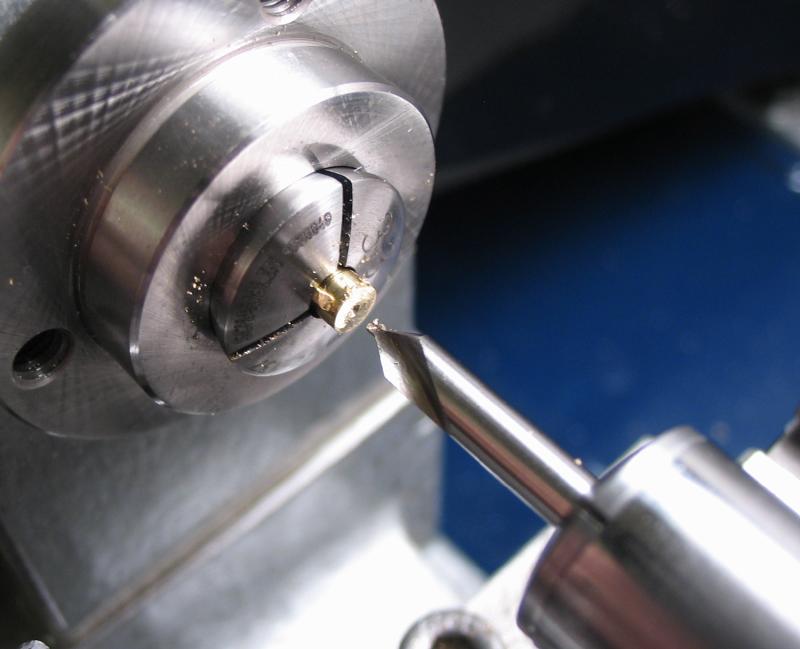
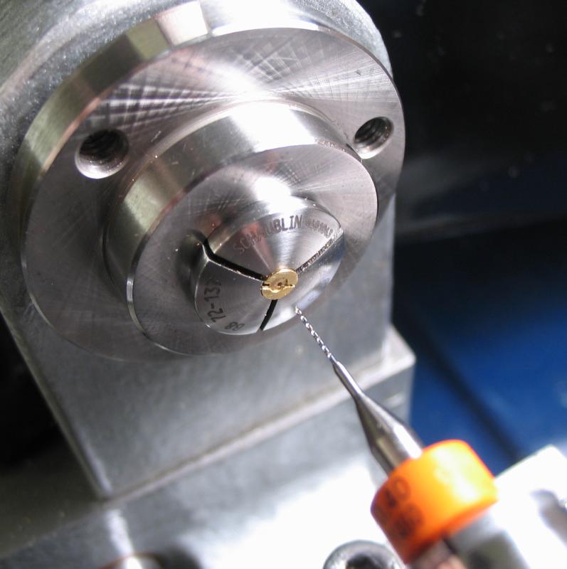
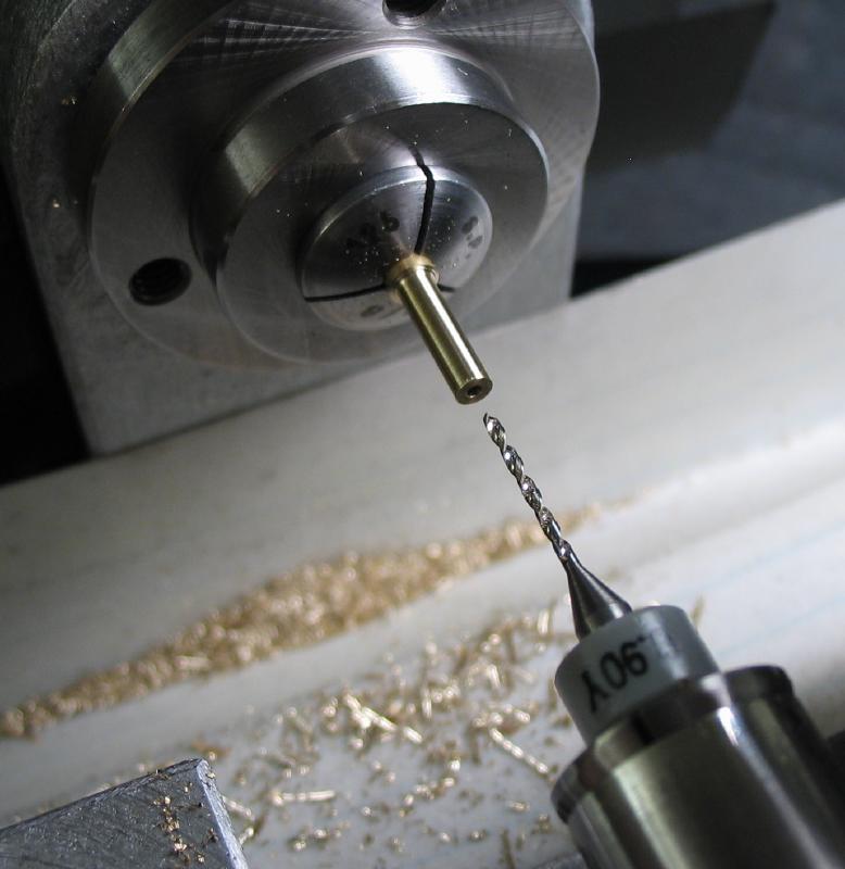
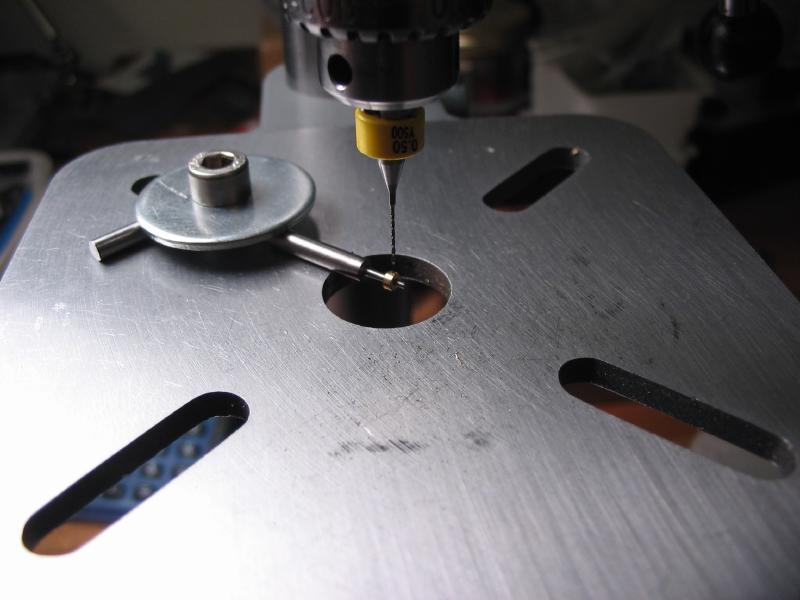
The discs can then be held for drilling. First center drilled with a #00000 Keo center drill, followed by 0.4mm drill.

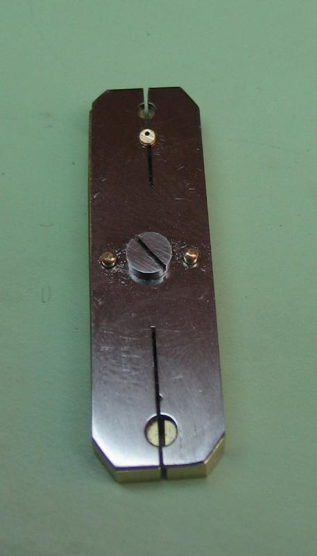
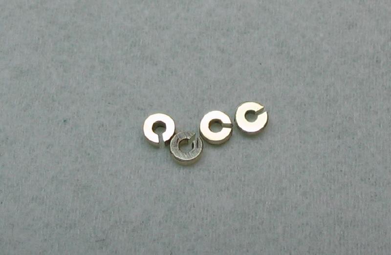
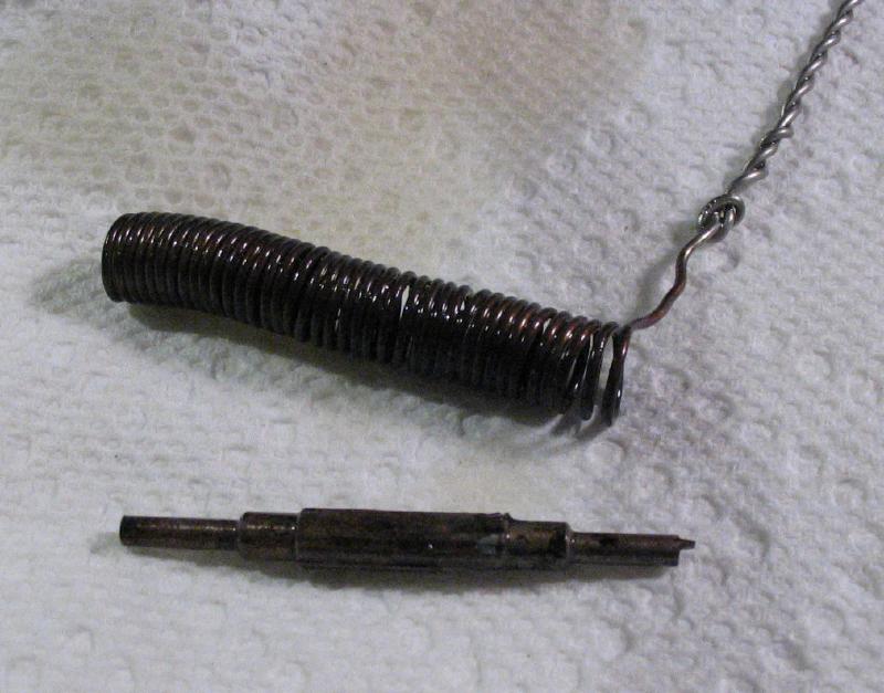
The weights must now be slotted. In figure 617 Daniels demonstrates what he calls a "spring clamp" to hold the drilled discs for slotting. I do not recognize the tool, but it appears to be straightforward to make one. I describe the construction on a separate page.
 |
 |

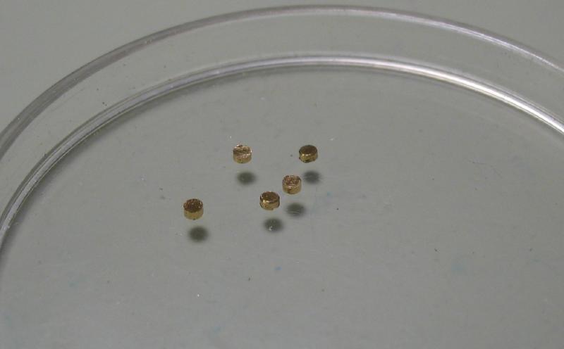
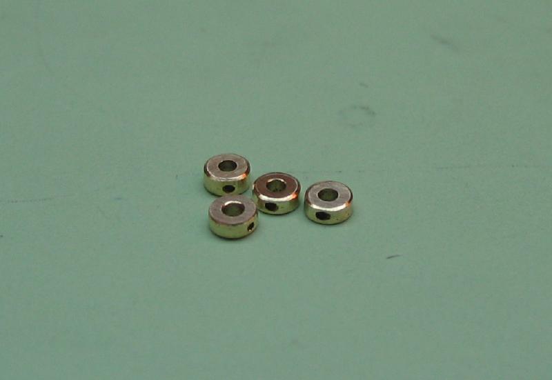
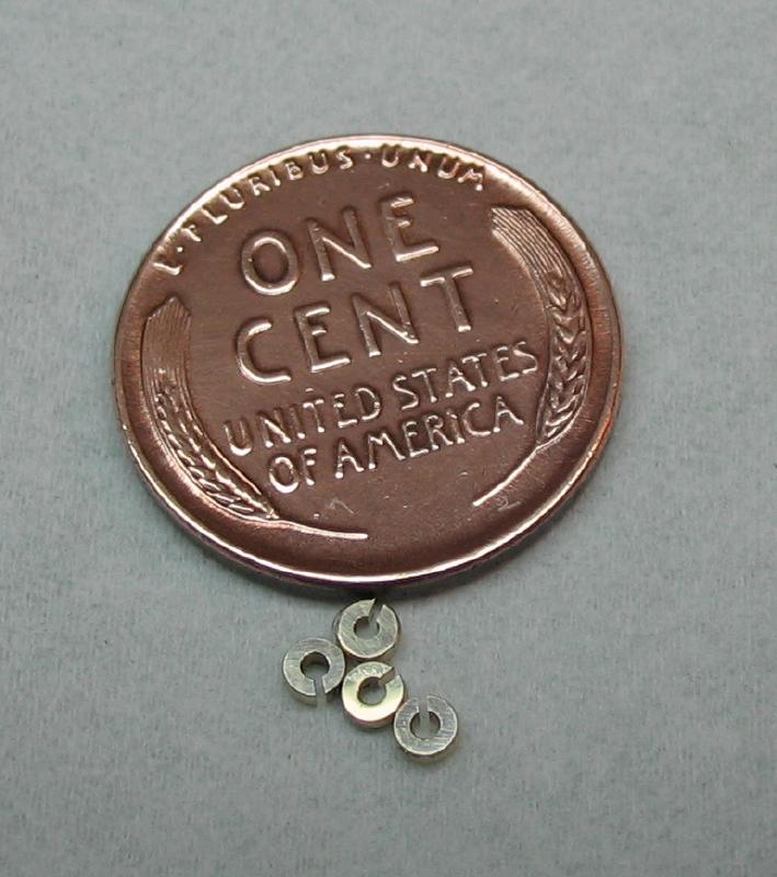
Of course quite a few had to be made until four acceptable ones were made.
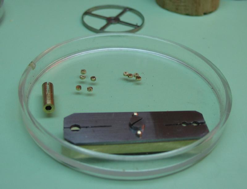
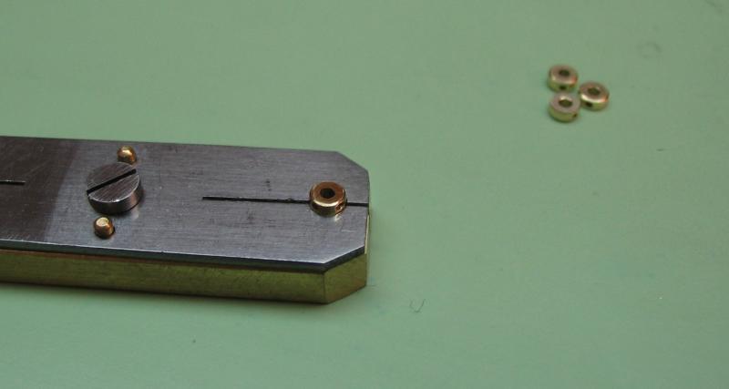
The weights are pressed on with the staking tool. A 0.50 mm flat punch and a simple flat stump were used.

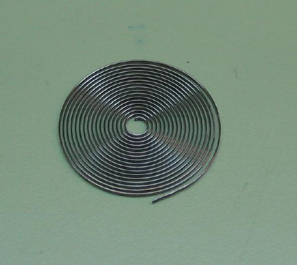
Balance Spring
The balance spring or hairspring is one of the few components that I will not be attempting to fabricate from scratch. Not only would it require specialized equipment to draw and form the wire, but the alloy of metal would not be equal to those used in modern balance springs. This not to mention that even with a fresh new hairspring, correctly mounting, bending, and bringing it to time is a formidable task for the beginner. Just locating new stock springs is not easy, they are not stocked by the supply houses and the system of measure is not straight forward. I located a small supply of springs, and I must admit, they simply looked like the appropriate size from what I have been able to find. We shall see how they work out.
From the photos, you can see they are composed of Elinvar and are size: Gr 2 / Fce 0.
Elinvar is a nickel steel alloy with a modulus of elasticity which does not change much with temperature variations. The name is a contraction of the French Elasticité invariable. It was invented around the 1920s by Charles Édouard Guillaume, a Swiss physicist. Guillaume won the 1920 Nobel Prize in Physics for these discoveries, which indicates how important these alloys were for scientific instruments. The package references various patents for various countries. I located these patents and combined them into the file below.
| CE Guillaume Patents |
  |
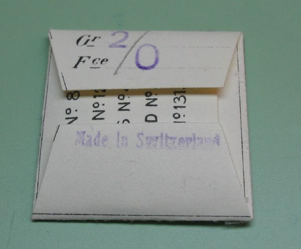  |
I could not find these units of hairspring measure in any of my references, and does not correspond to the modern system of measure. "Gr" likely refers to "grandeur" meaning size, but this may be an arbitrary unit. "Fce" may refer to "force", but again not very informative from what I have.
There are a number of complicated calculations that one can perform to arrive at the correct hairspring, however, these calculations require that you know the technical specifics of your components, such as the elastic couple of the spring, modulus of elasticity of the spring, the balance's moment of inertia, etc. etc.
In practice a spring is fit by a sort of trial and error process. Two excellent books which detail practical knowledge on fitting and adjusting hairsprings are Hans Jendritzki's "Watch Adjustment" and Henry Fried's "Bench Practices for Watch and Clockmakers."
| Watchmakers Handbook - Saunier - Polishing Hairsprings |
Hairspring Collet
 |
 |
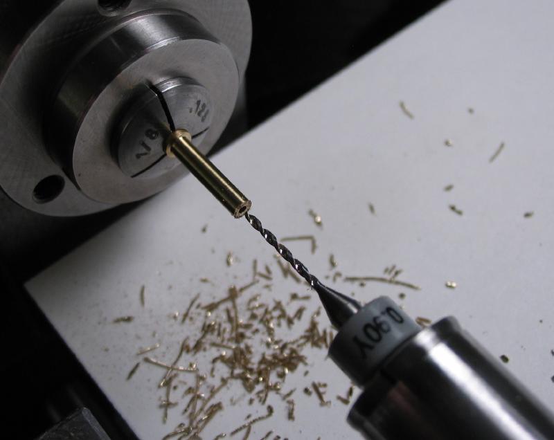
The hole to fit the balance arbor is center drilled and drilled 0.9mm.
 |
 |
 |
 |
There are many photos because I had to make quite a few until I had any success, and I rephotographed the process. I don't think I ever mentioned it, but the reader may notice I use index cards; folded and/or cut into shapes to fit under the headstock, these help collect chips and swarf and help keep things tidy...
The collet can be parted off to a thickness of 0.90mm, I made them a bit oversize to be finished later.
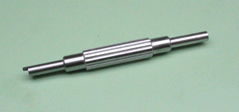
They will be threaded onto a tapered arbor, which is much easier to hold for the final operations. Of course, this arbor needs to be made. Turned from 3mm O-1 drill rod and given a 2 degree taper and to fit the embryo collets.
The arbor was parted off, and fully hardened in oil.
Now for the tricky part....
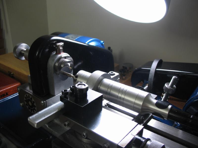
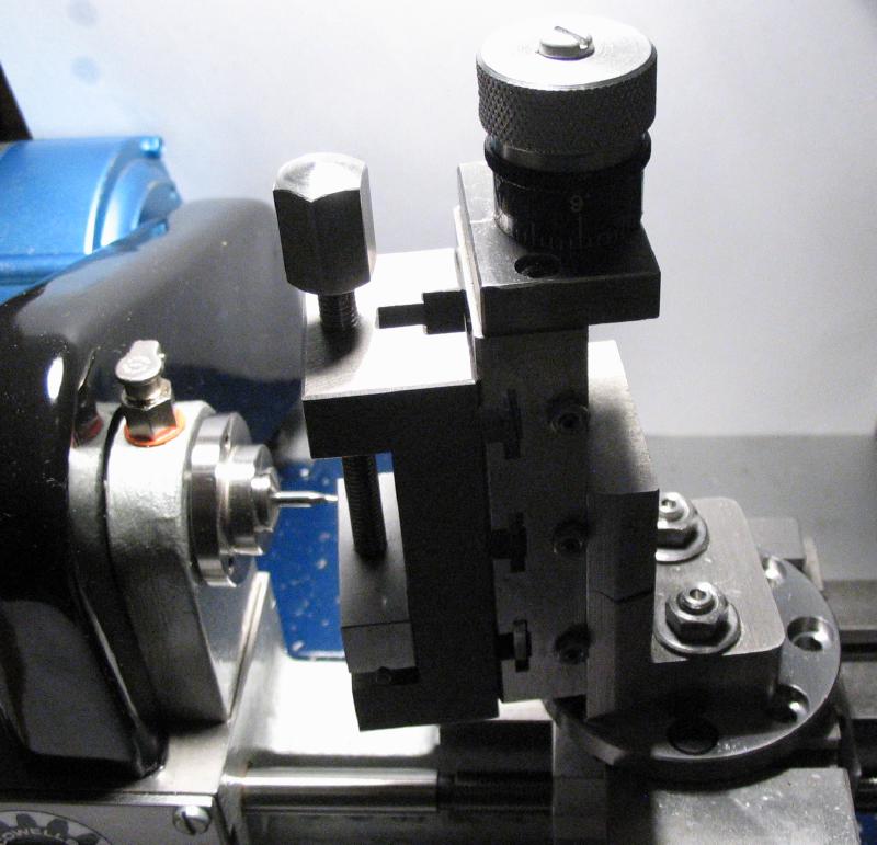
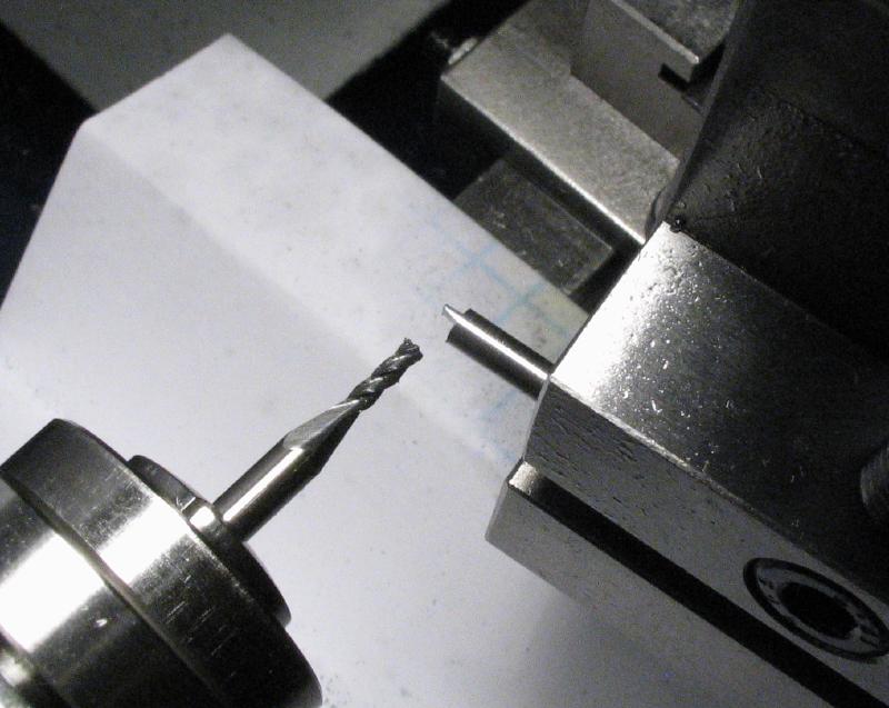
The collet needs to be drilled off center for the hairspring pinning point. This is a 0.5mm hole, and there is very little room for error. To start this hole a chamfer is made. The collet on the arbor is held on a cone stump to keep centered and the chamfering punch is used to make a start. The following is not pictured; the stump is swapped for a regular flat stump, and the chamfering continued. The arbor (and collet) is slowly rotated while continuing to chamfer. This is continued until the chamfer is heading in the direction needed to be drilled.
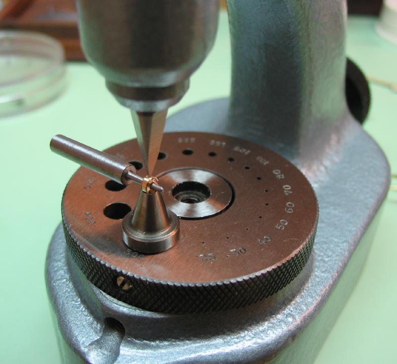
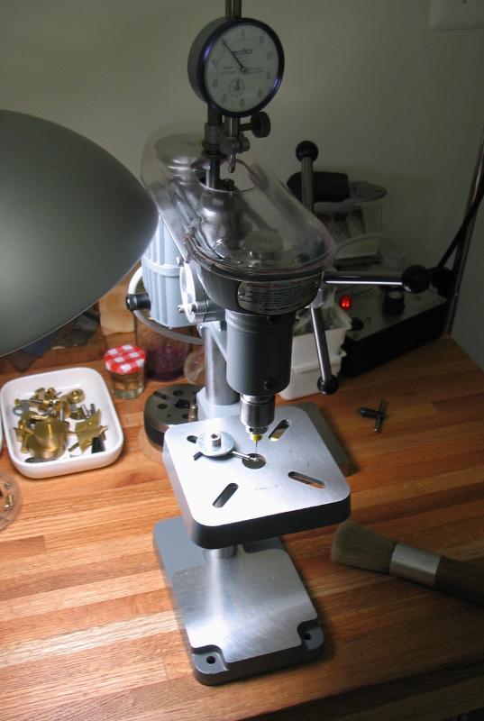
The work is transferred to the drill press, it was clamped to the table and positioned for drilling. I ruined about eight collets until I drilled one successfully!
 |
 |
The arbor and collet is mounted on the lathe and a very fine file (Swiss cut 8) is used to polish the diameter and remove any wayward chamfer marks.
The slots must now be cut. The spring clamp made previously for slotting the balance weights is used to hold the collets. The staking tool was used to help insert the collet evenly. They are slotted with a 0.012" slitting saw held in the headstock.

The spring clamp is held in the standard toolpost. It was made square using a machinist square against the compound slide.
 Before slotting |
 After Slotting |
 |
 |
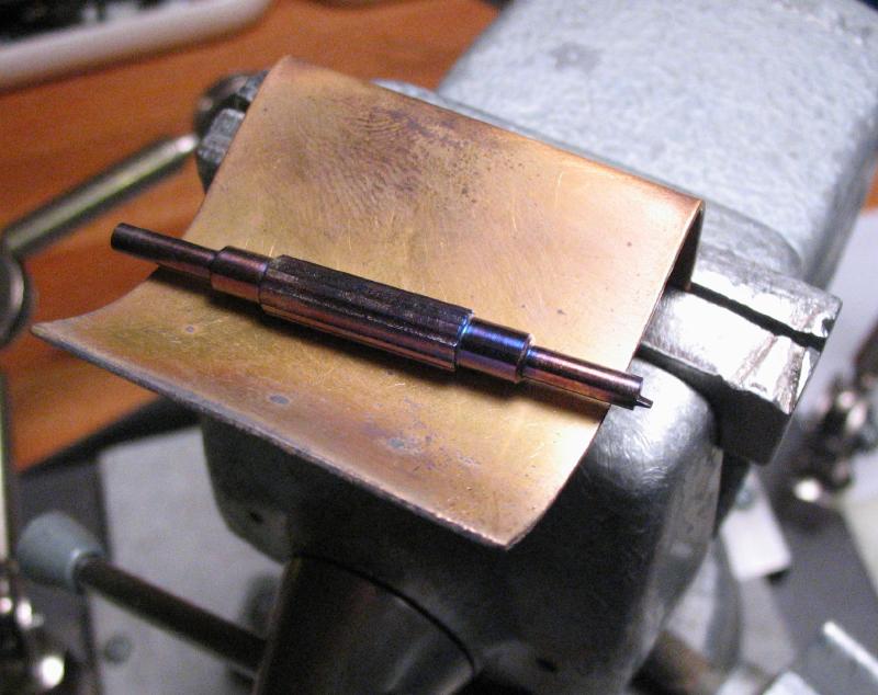
A small tool was made for pressing the collet onto the staff or rotating the collet while in position, it is similar in design to the Bergeon 30017 series, however, this particular size is not available. It was made from a 55mm length of 5mm oil-hardening drill rod, found in the scrap box, although a longer length would likely be advisable. Each end was turned down to 2.6mm for about 10mm, drilled 0.95mm, and one end was then countersunk. A small 4mm step was turned and the corners relieved.
|
|
|
The other end of the tool was milled to leave a 0.5mm wide and 1.25mm long tab remaining. The recently made adjustable mount was used to rotate the vertical slide to about 7 degrees and the tab was milled on its sides to give a wedge shape that is about 0.2mm at its tip. It was then held in a collet with tailstock support and the headstock locked, the handle portion was fluted with a 1/16" ball end mill and indexed through 10 positions.
|
|
|

|
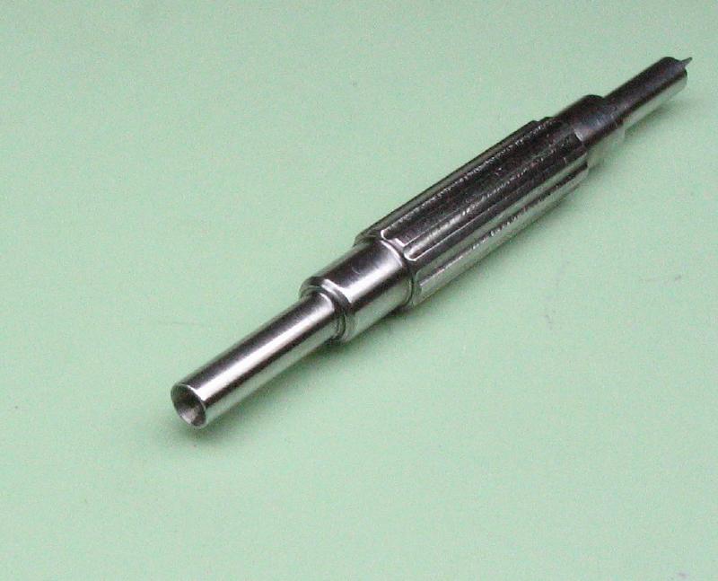
The tool is shown after machining is complete. It was wrapped in binding wire, coated in boric acid, and hardened in oil. After cleaning and polishing, it was tempered on a brass plate. The gripping portion in contact with the plate was heated to a blue color and tips were still straw colored - although the exact temper is likey not critical here.
|
|
|
It could then be polished up again. The countersunk end can be used to press the collet onto the balance staff, and the end with the small wedge used to rotate the collet.
|

|

|
Forming the Overcoil
| dumont_hairspring_coiling_tweezers.pdf |
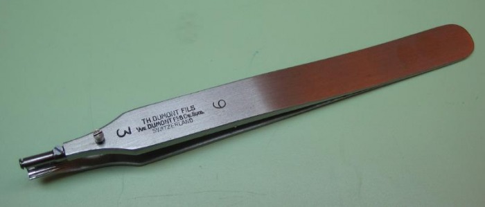

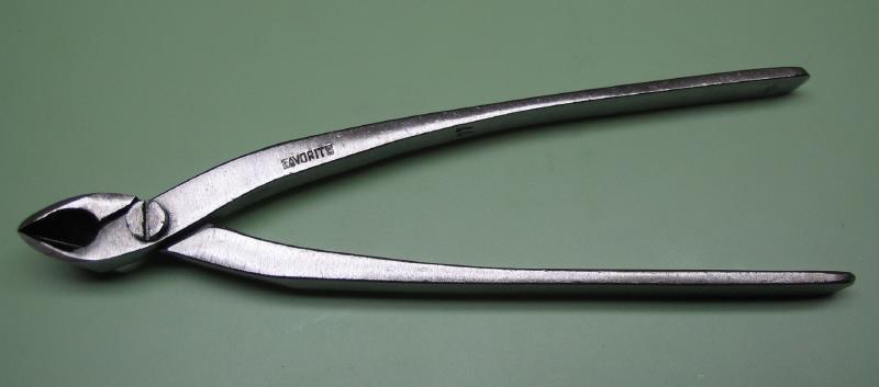
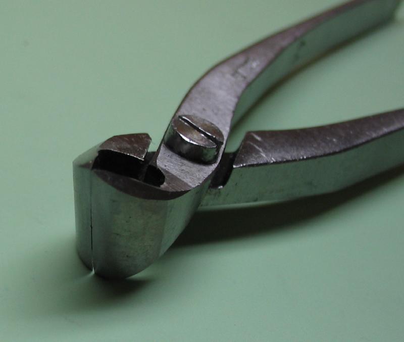
For cutting hairsprings, a fine, flush-cutting pair of nippers is desirable to cut the spring and leave a clean cut. This is an old pair of Favorite brand cutters (No. 77). I believe Dumont still manufactures similar cutters (see catalog pages below), but they do not seem to be readily available in US. This pair was purchased cheaply, and the cutting edge is still in good condition. It appears that at some point they were used to cut something too thick and left a nick in the middle of the blades, but for hairspring use only the tip is needed. The cutters can be disassembled and the edges resharpened.
|
| ||
