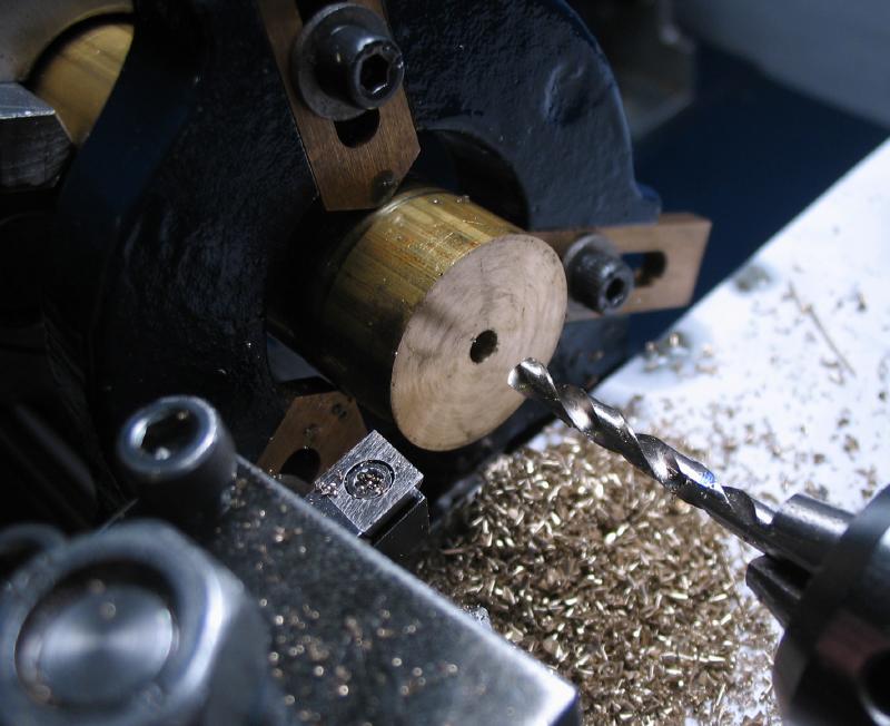
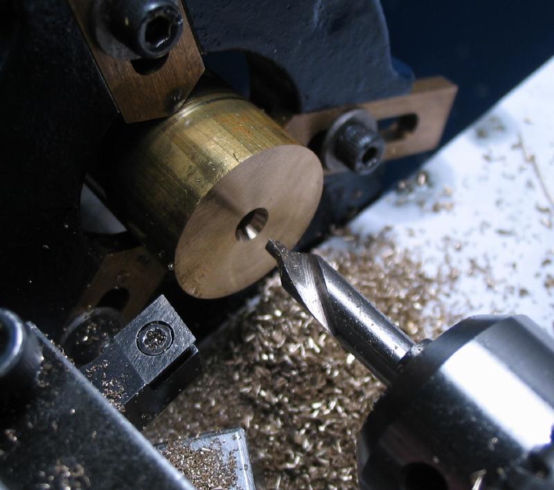
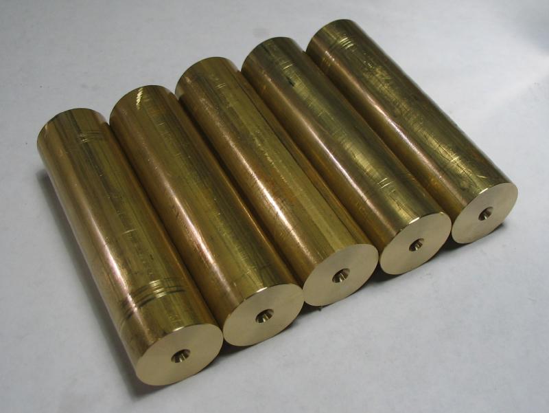
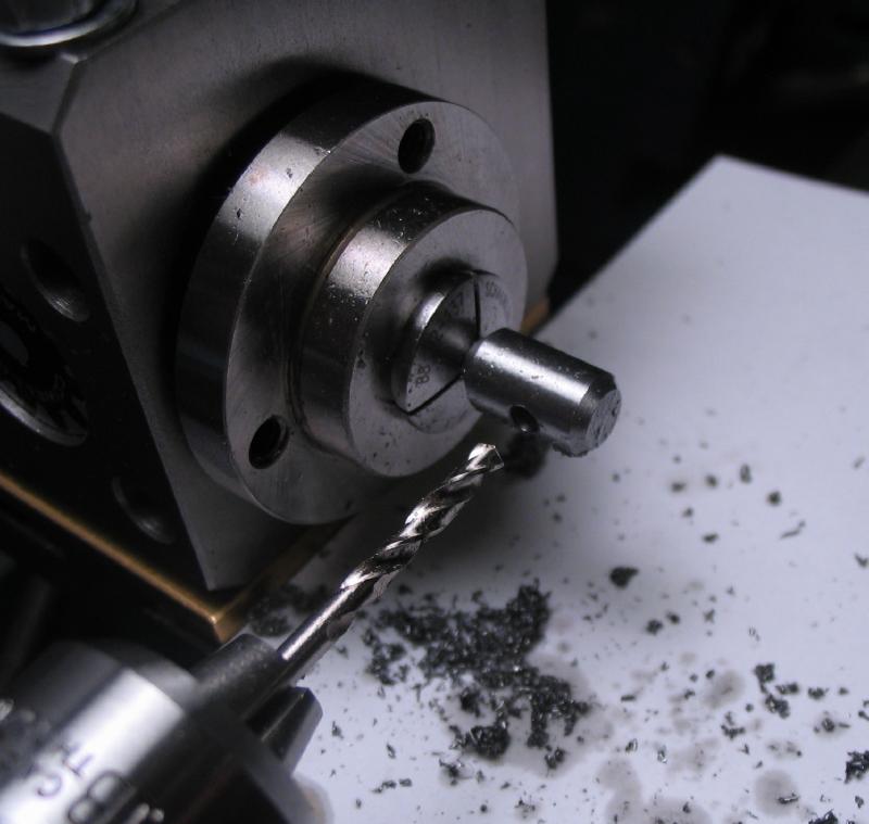
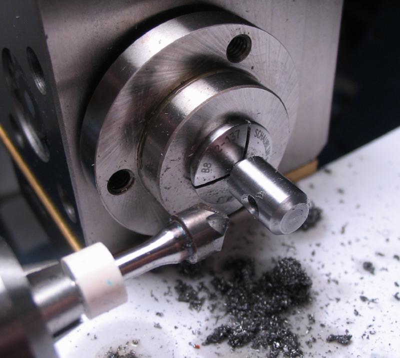
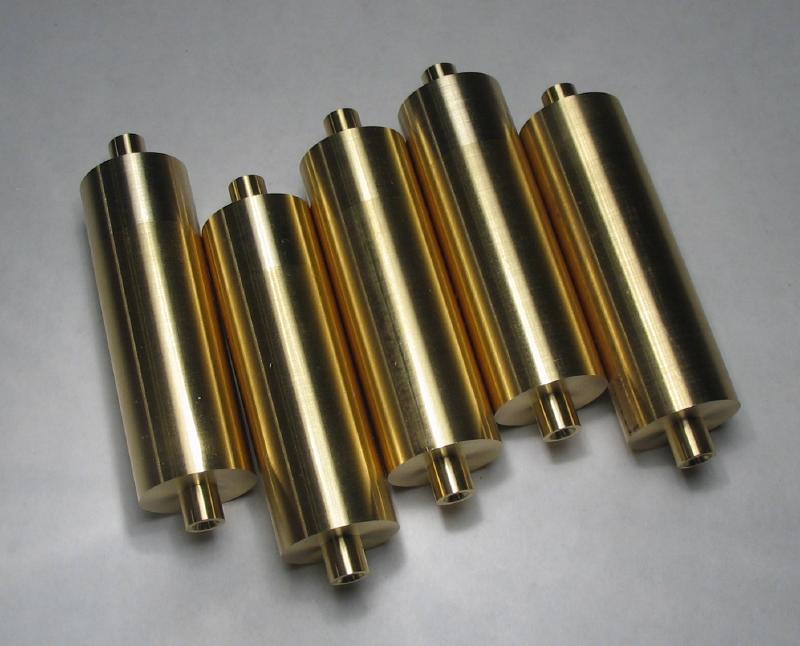
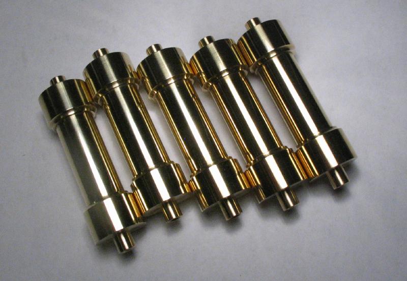
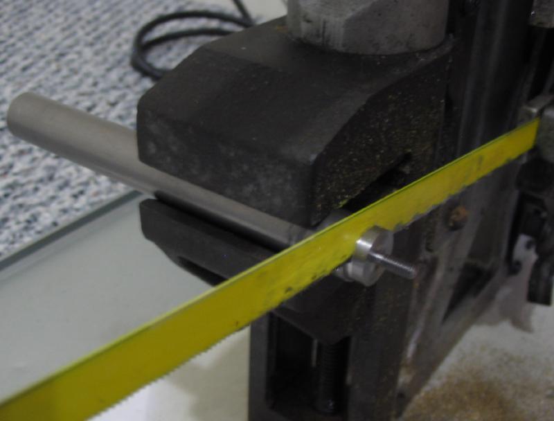
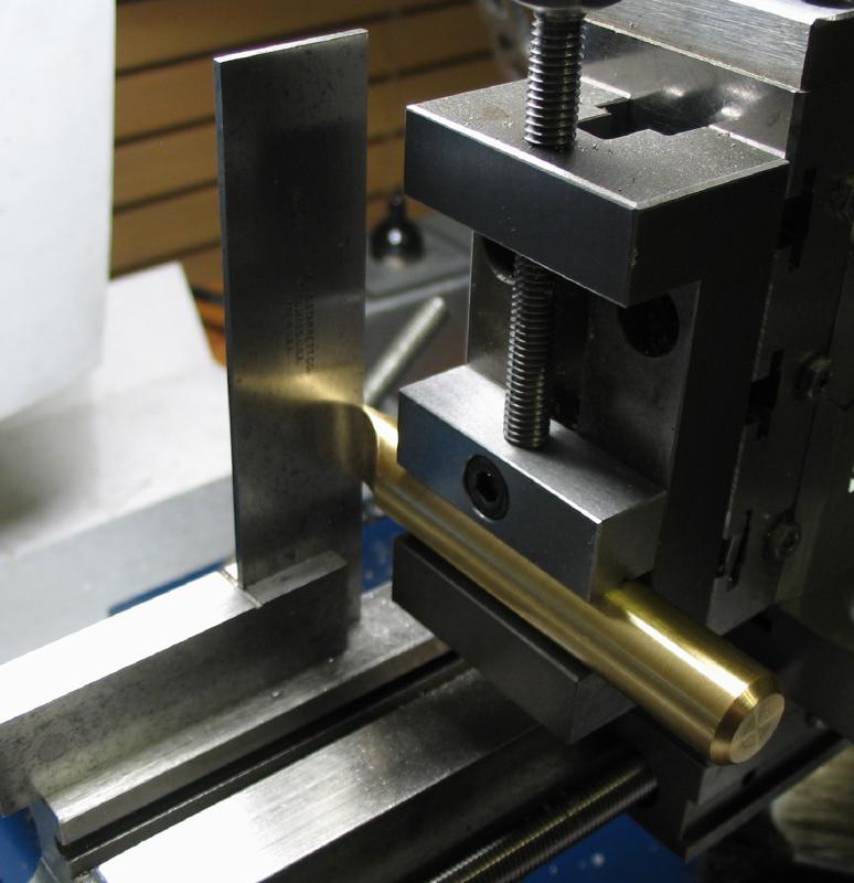
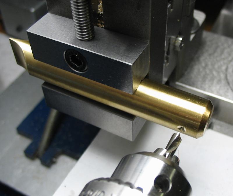
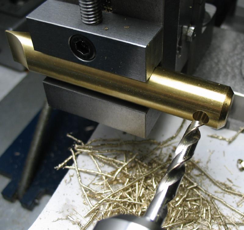
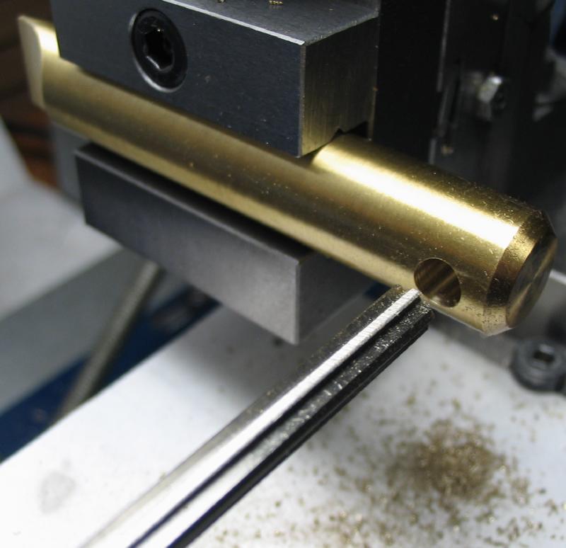
The pillars were made as a batch of five from 3/4" diameter brass rod. The blanks were sawed off that are a few millimeters longer than needed. Using the steady rest, the ends of the rods were faced, drilled for #6-40 threads, and countersunk with a center drill.

|
|
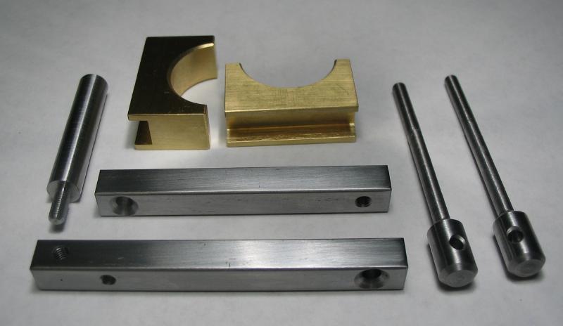
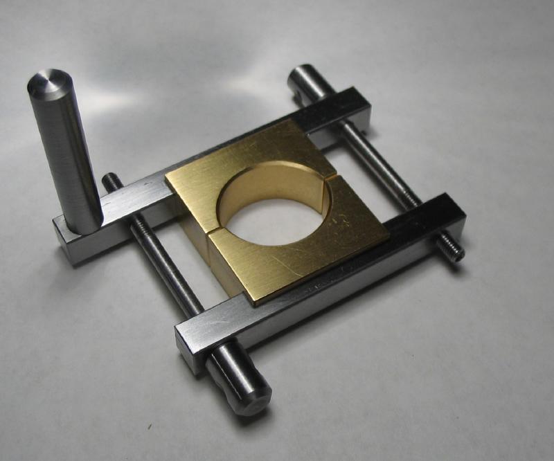
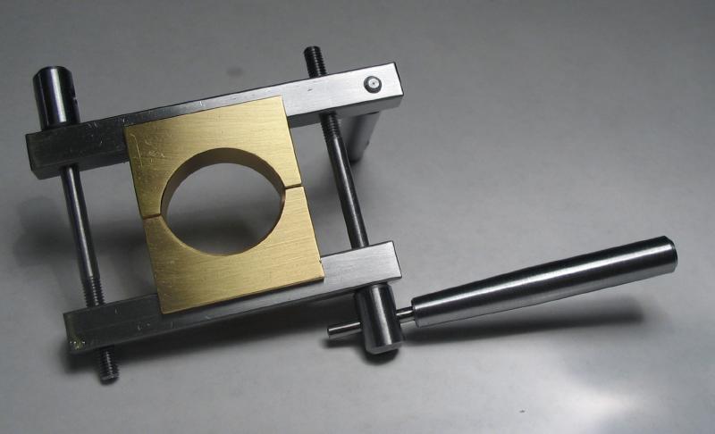
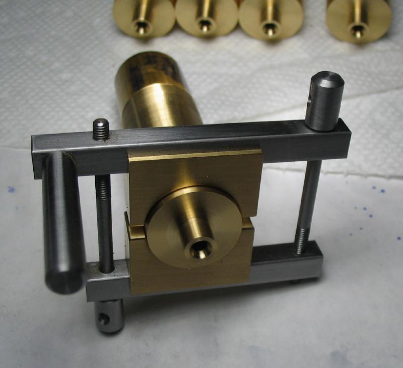
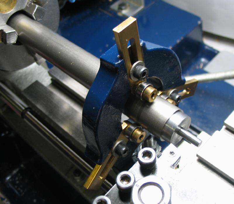
The next step is carried out with the work mounted between centers. I did not have a drive dog large enough to accommodate 3/4" rod, so one was fabricated. The clamp is made from 1/4" square steel, and threaded for M3 screws. One arm of the clamp is longer than the other to hold a drive pin (may be better to make them the same length to help balance the weight). To avoid marring the work to be held, a brass insert was made that is both milled to mate with the clamp arms and bored to fit the 3/4" rod. The insert was sawed in half and shortened. Stock countersunk screws could be used, but not having any on hand that were long enough, a pair was turned from 1/4" drill rod. They were cross drilled for tightening with a tommy bar that was fashioned from a short length of steel rod and the 3/32" shank of broken microdrill.
|
|
|
|
|
|
|
|
|
|
|
|
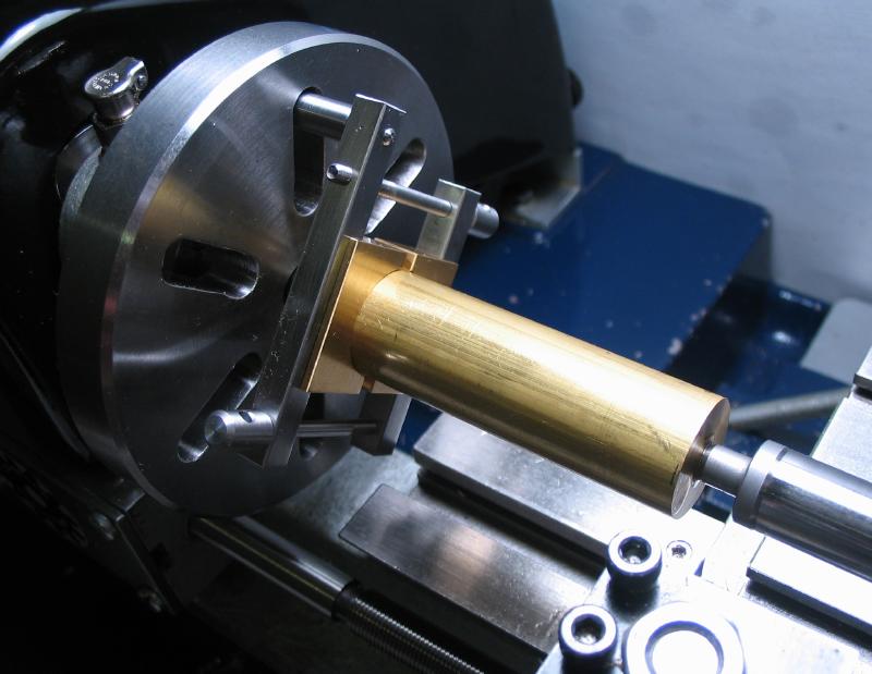
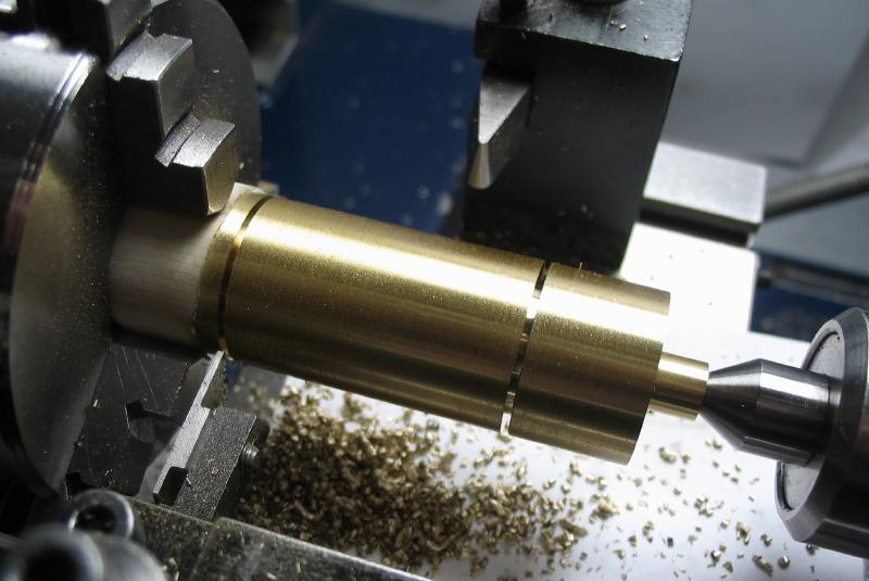
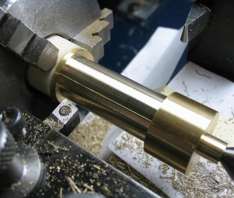
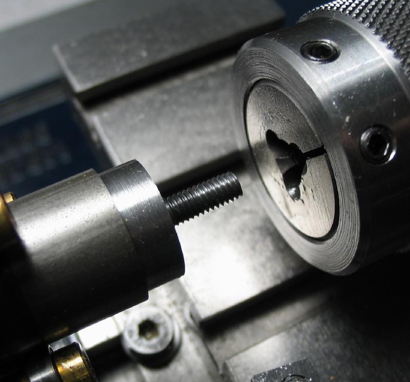
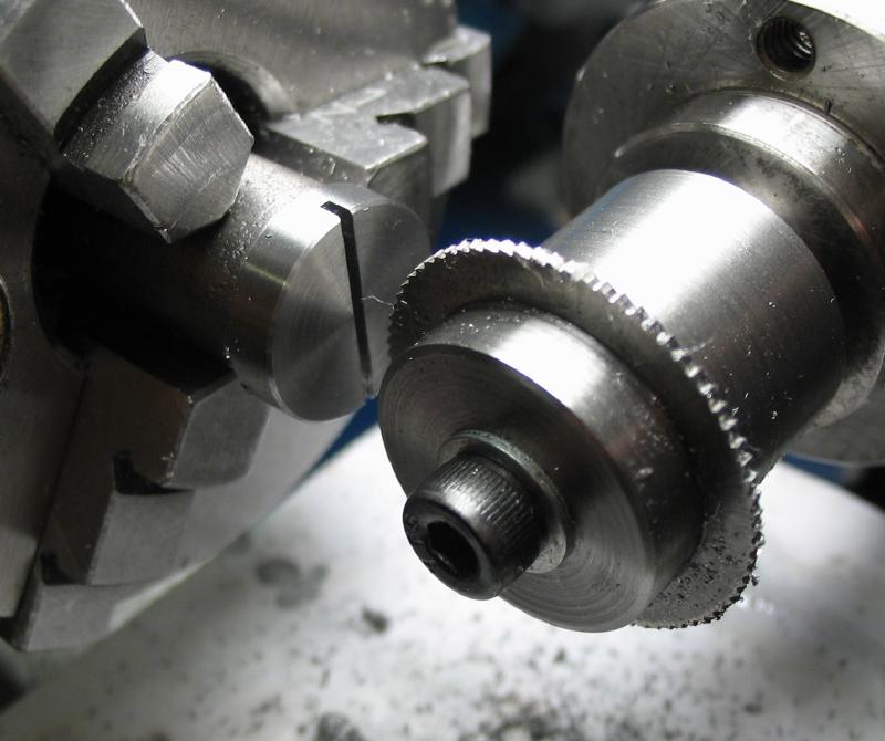
The pillar blank is clamped in the dog and setup between male centers in the headstock and tailstock. The pin on the dog mates with a slot of the faceplate. Each rod is turned true for the available length and the spigot turned that fits through the clock plates and extends into the washers as well. The shoulder face was given a slight undercut to ensure the pillar will seat on the outer diameter of the face.

|
|
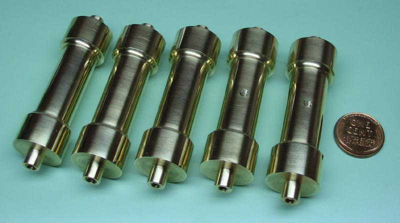
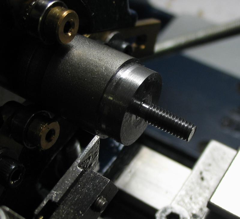
The reverse end of each rod was then turned and the matching length of each pillar established - this was decided as 57.2mm, slightly under 2.25", but this dimension will be repeated with other components that fit between the plates. My blanks were a couple millimeters too long, so some of the second spigots will need to be shortened, but not until all turning is completed.
Since the brass inserts of the drive dog are movable prior to tightening, it was found that offsetting the work helped to balance the weight.
|
|
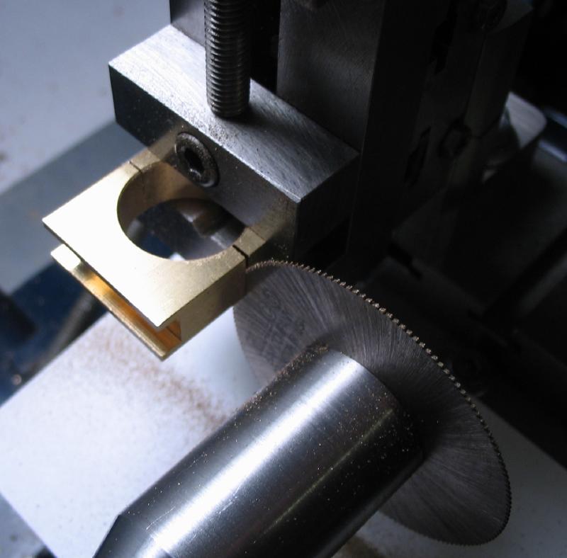
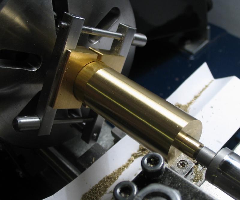
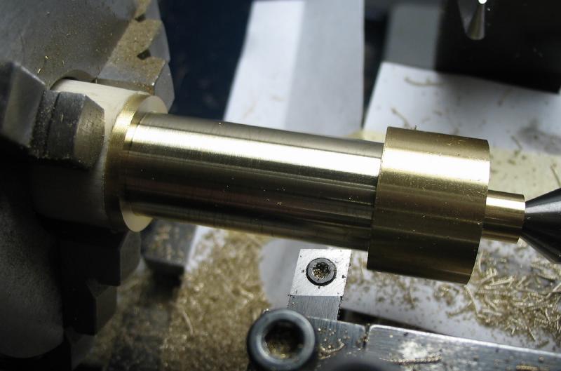
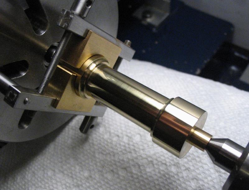
The tailstock dead center was replaced with the rotating center and with the work held in the 3-jaw chuck, the waist portion of each pillar was turned. A parting tool (1/32" width) was used to form the edges of the waist and plunged to almost full depth. Right- and left-cutting tool bits were alternately used to reduce the waist to final diameter (the quick-change tool post was very helpful here). Finally, a round nose tool was used to radius the corners.
|
|
|

|

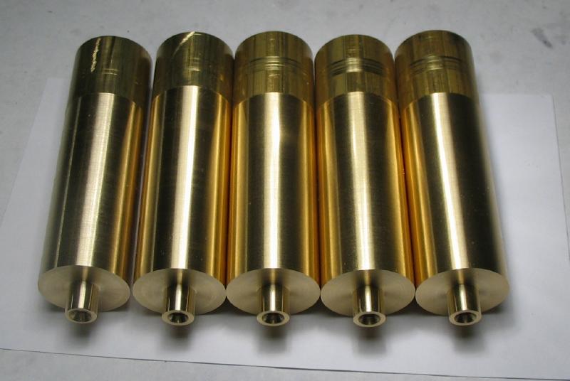
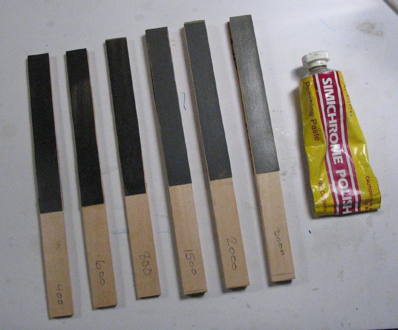
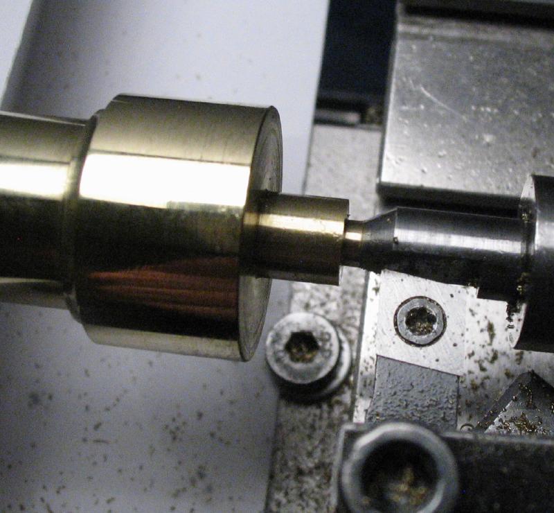
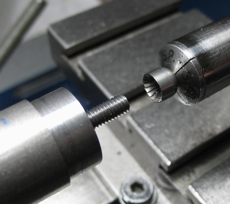
The finish was improved with emery paper that was glued to wood strips and the final polish applied with Simichrome and cotton rag. The polishing was carried out between centers, but only because the drive dog is less likely to mar the surface than the 3-jaw chuck. The spigots were given a slight taper and the corners chamfered with needle files. After all other turning was complete, the oversize spigots were reduced using a half-center for support, and for one excessively long example the center of the work needed to be retained leaving a very thin wall that was removed afterward with a countersink.
|
|
|

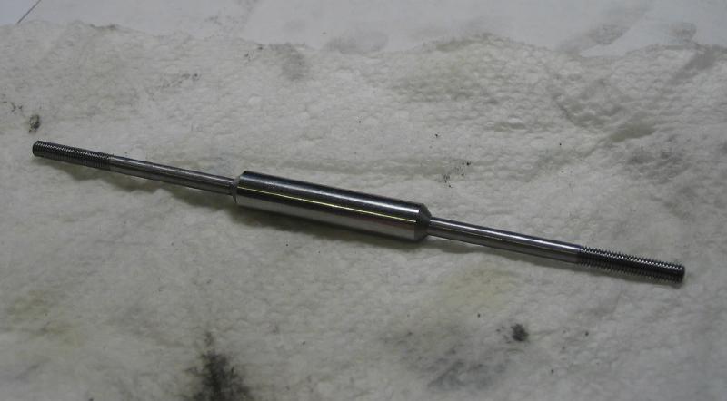
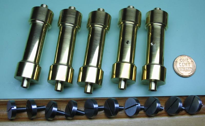
Before and after
|
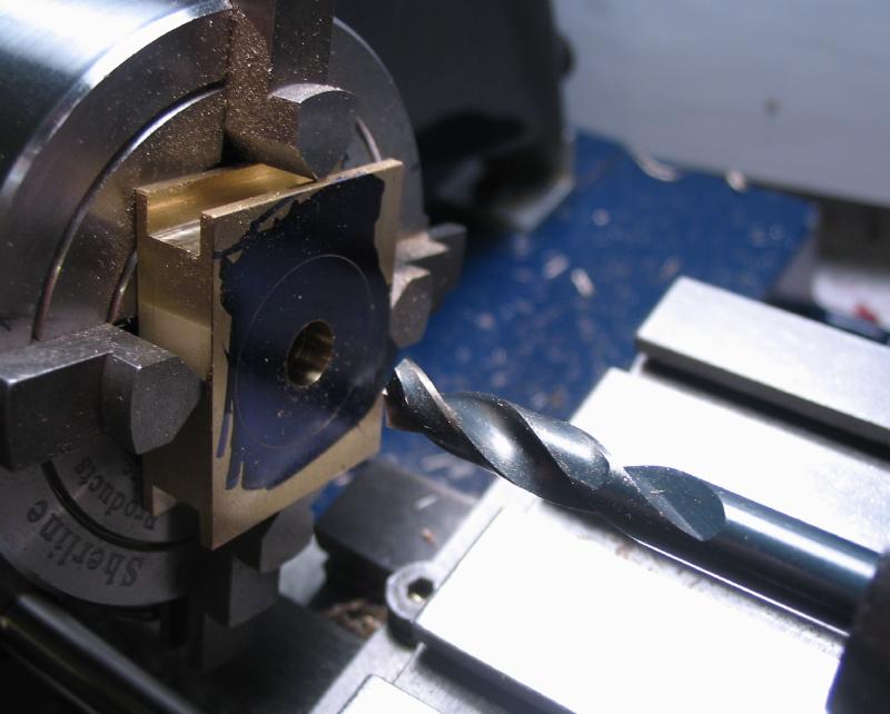
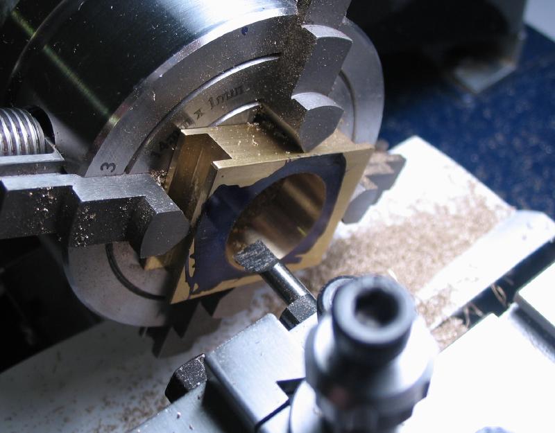
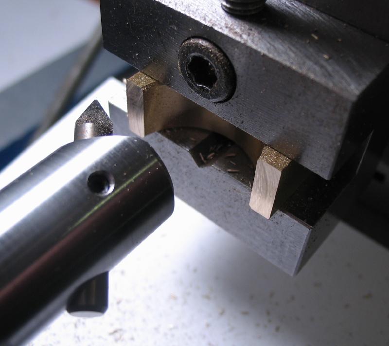
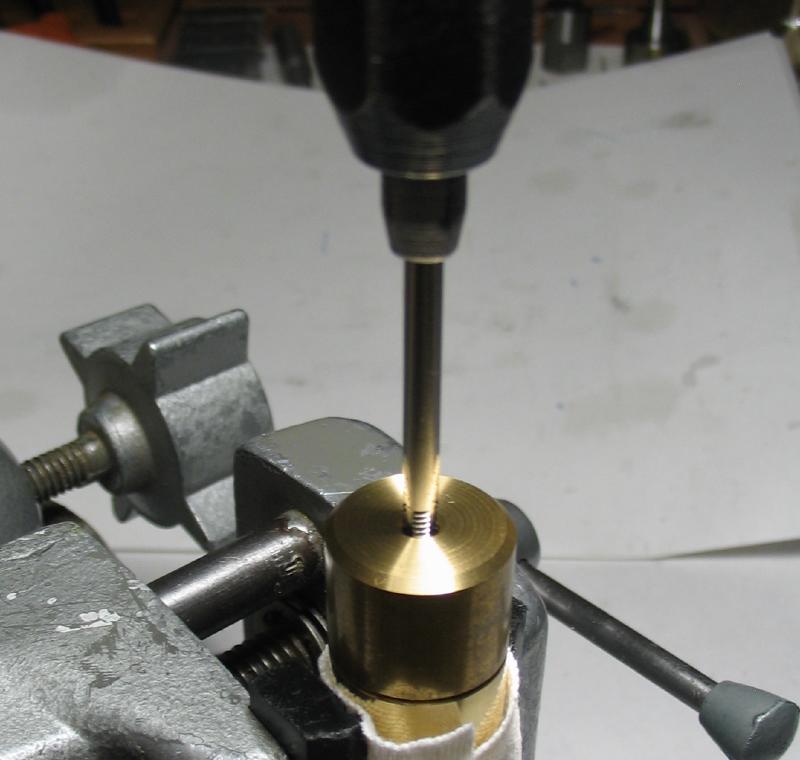
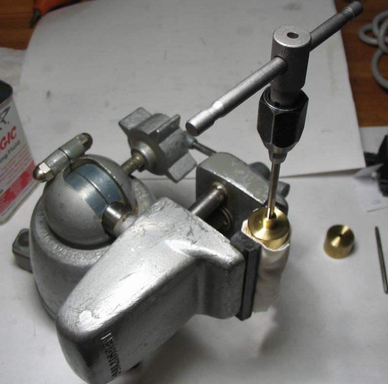
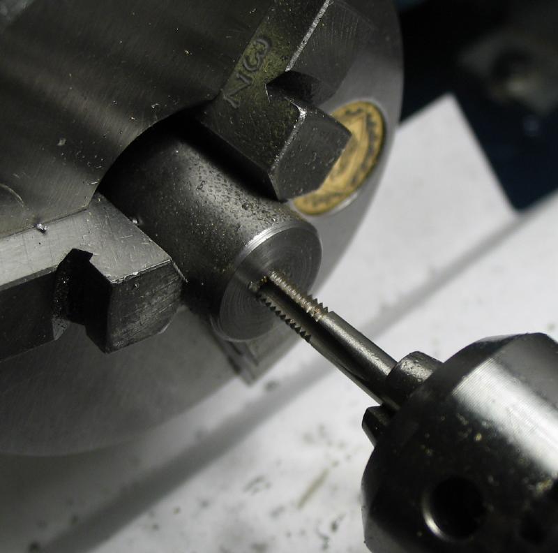
With all the turning steps completed, the ends can be tapped. This was carried out with the pillars held in a vise with nylon jaws and cloth wrap to prevent marring the finish. To keep the tap upright when starting, a guide was made from a short piece of brass rod. The guide is drilled to clear the tap and counterbored to fit over the spigot on the ends of the pillars. The guide limits the depth the tap can reach, so it was removed prior to taking the threads to full depth and finishing with a bottoming tap.

|

|
|
|
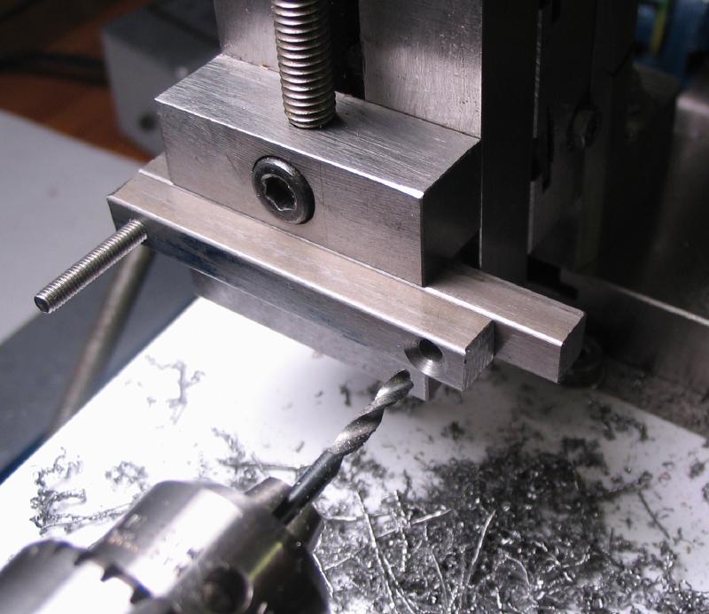
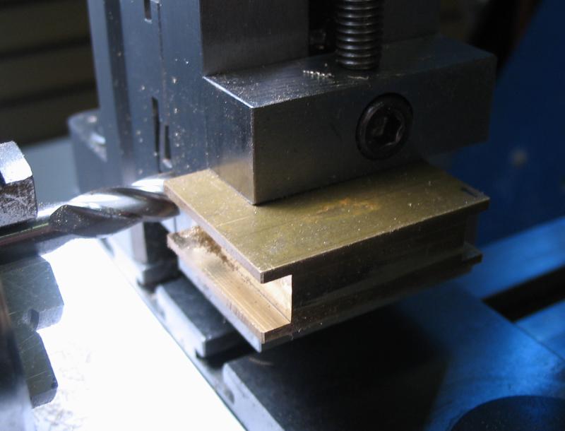
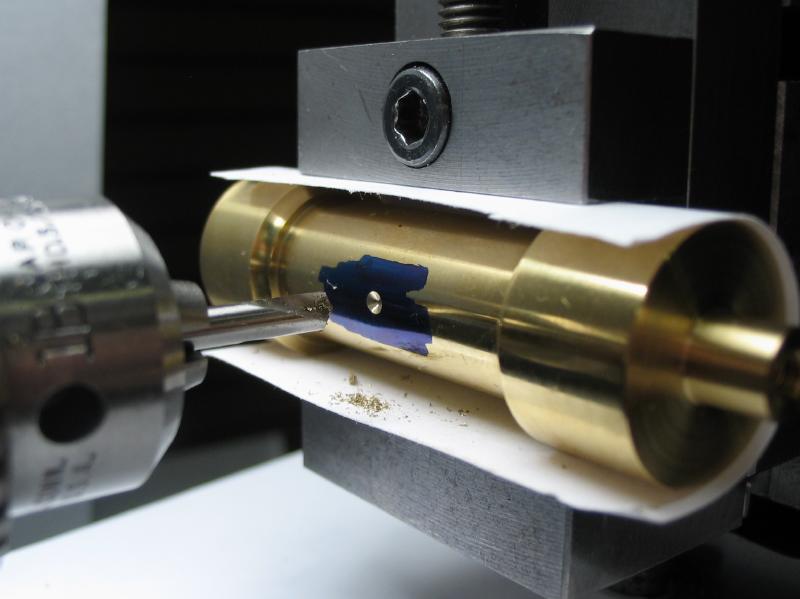
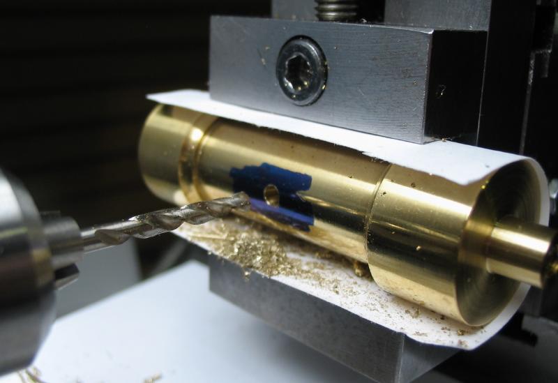
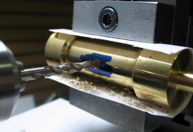
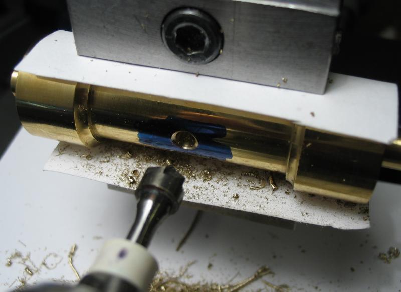
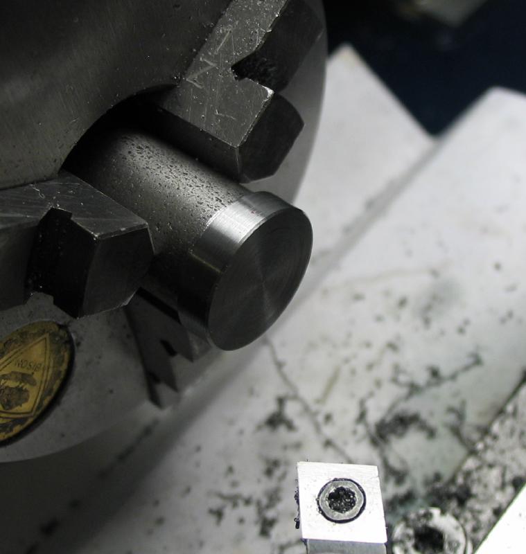
Two of the pillars were selected to be cross drilled and tapped for mounting screws. I used #5-44 (UNF) thread in place of 5 BA and counterbored the hole to about half its depth with a #30 drill. The counterbore acts as a convenient guide for keeping the tap upright.
|
|
|
|

|
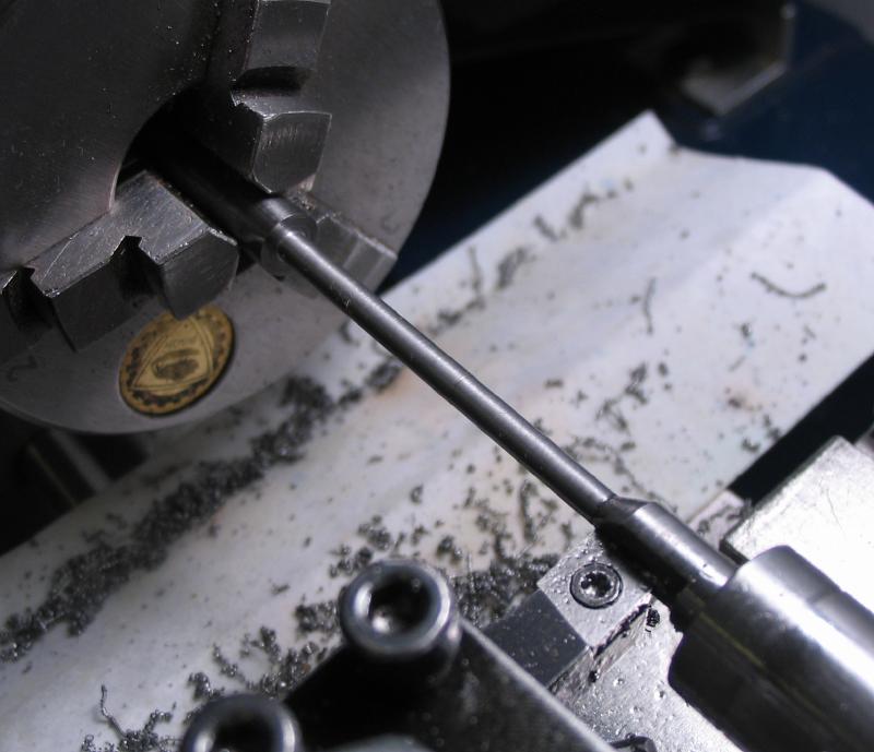
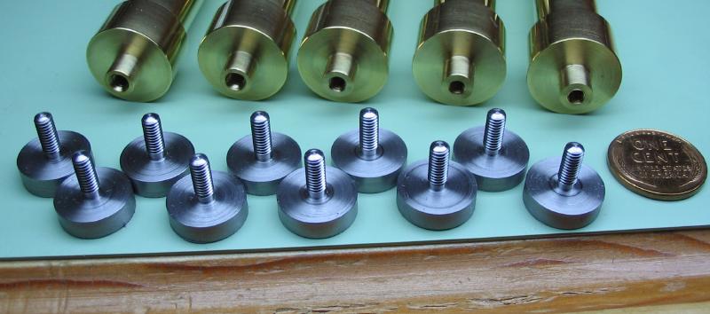
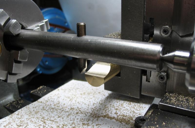
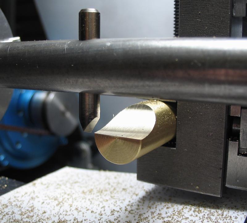
Each pillar requires a pair of screws and washers. The ten screws were made from 5/8" diameter steel rod. Since this is too large to pass into the headstock, the steady rest was employed to minimize waste. The rod was turned, threaded, a parting tool used to remove the partially threaded portion near the head, and the tip rounded over with a up bur. The screw was then parted off with a saw.
|
|
|
|
|
A mandrel was made for holding the screws while finishing the top faces. The mandrel is simply a length of steel rod tapped with a matching thread. The screw heads were faced and brought to the correct thickness, and then the slot formed with a 0.032" slotting saw. The screw heads were given a quick finish on 400 grit paper, but being very early in the construction, the final finish will be left for later on.
|
|
|
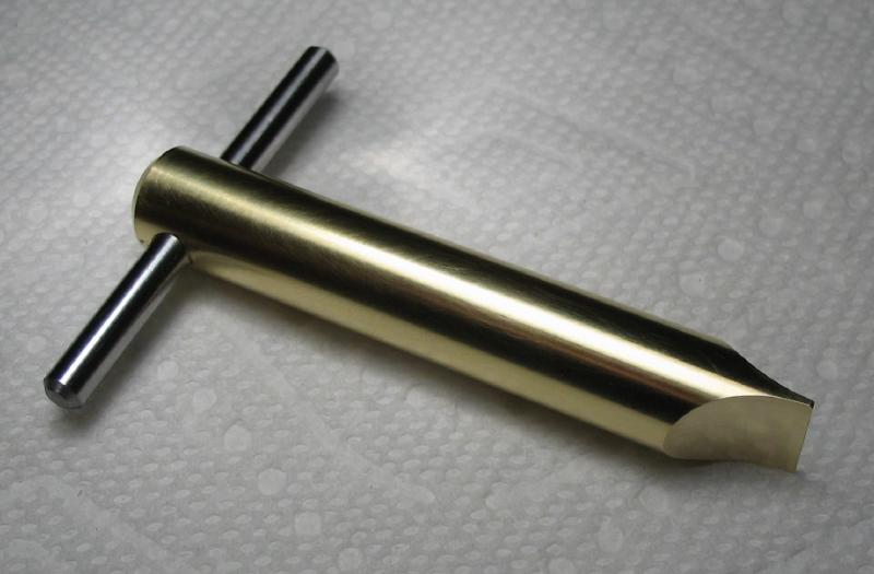
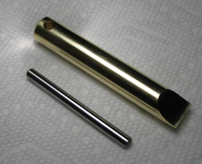
A special driver was made to fit the screws to prevent marring the slot. It is made from 1/2" brass rod and the radius shape of the side of the blade formed by fly-cutting. The flycutter was made previously from a length of steel rod and the cutting bit is the same described from another style of flycutter.
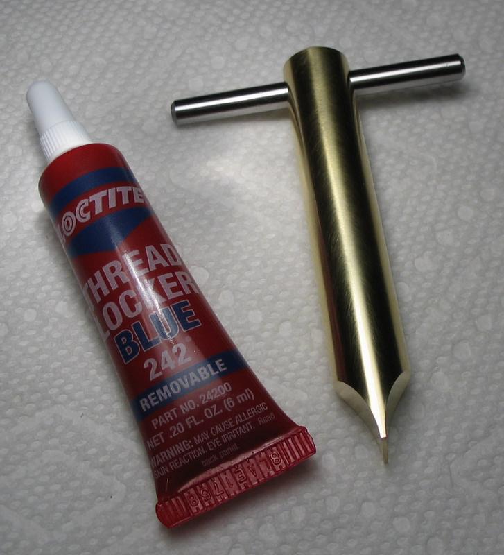
The hole for fitting a handle was drilled and reamed and a steel handle secured with Loctite. The handle is a piece of drill rod with the end chamfered.
|
|

|
|
|
|
|
|
|