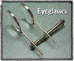
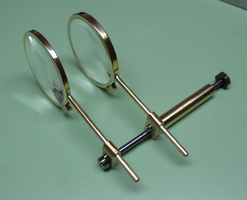
Eyeglasses for Eyeglasses
There are various options for simple magnification for the eyeglass wearer. Many of the commercially made loupe-type contraptions attach to the side of the eyeglasses frame. When working at close magnification the focal length is only a matter of centimeters, and the contraption holding the lenses frequently gets in the way of the hand doing the work. Daniels points this out in 'Watchmaking' and recommends a system that mounts the eyeglass contraption from the bridge of the eyeglasses frame or the center of a headband. In many photos he can be seen wearing what appears to be home made solution. This is understandable since there doesn't appear to have ever been a commercially made version with that arrangement.
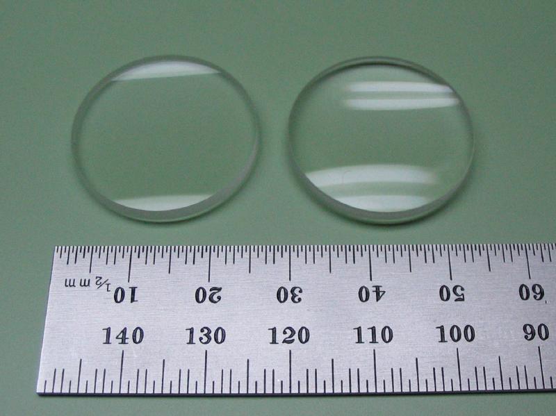
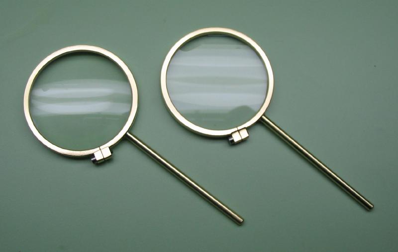
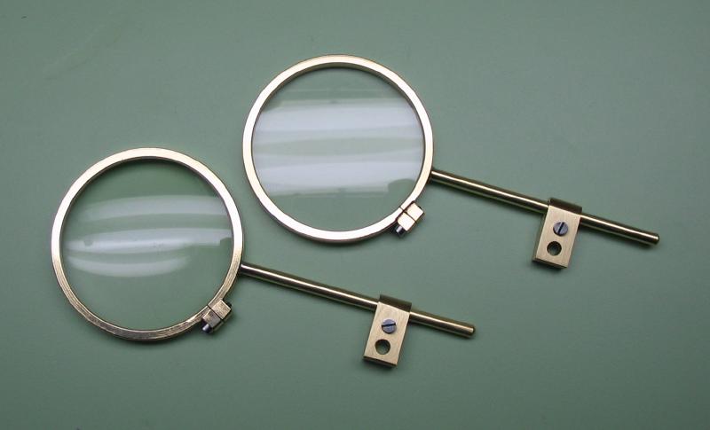
This page will detail my attempt at making a doublet eyeglass to attach to prescription eyeglasses. For this project I am starting with a pair of lenses from Edmunds Optics. They are simple double convex lenses, 25mm in diameter, and in focal lengths of 5 and 10cm, as per Daniels' recommendation in "Watchmaking," and equivalent to approximately 2.5X and 5X magnification power. The magnification power (MP) of lens can be approximated using the assumption that the natural, near-point, focal length of one's eye is 25cm, thus the 'power' of a lens is equal to 25cm times the lens diopter (i.e. the reciprocal of the lens focal length in cm). MP = 25/FL However, the actual magnification is dependent on the distances between the eye, lens and object (adding upwards of another 'x').
This page will detail my attempt at making a doublet eyeglass to attach to prescription eyeglasses. For this project I am starting with a pair of lenses from Edmunds Optics. They are simple double convex lenses, 25mm in diameter, and in focal lengths of 5 and 10cm, as per Daniels' recommendation in "Watchmaking," and equivalent to approximately 2.5X and 5X magnification power. The magnification power (MP) of lens can be approximated using the assumption that the natural, near-point, focal length of one's eye is 25cm, thus the 'power' of a lens is equal to 25cm times the lens diopter (i.e. the reciprocal of the lens focal length in cm). MP = 25/FL However, the actual magnification is dependent on the distances between the eye, lens and object (adding upwards of another 'x').
| Edmunds Optics DCX Lens - 25mm dia - 5cm FL |
| Edmunds Optics DCX Lens - 25mm dia - 10cm FL |
A rough sketch and a gathering of materials for the job.
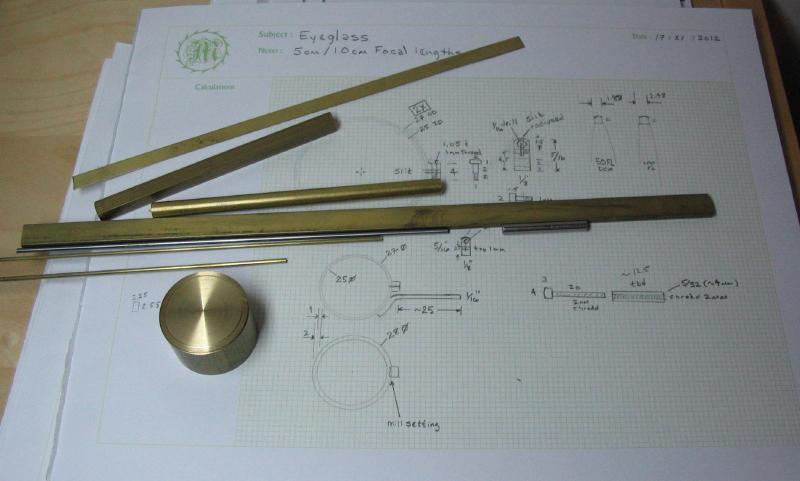
I deviated from the initial sketch a bit, but made a drawing in CAD software after finishing the work. A PDF print out is below.
| Eyeglasses - Dimensions |
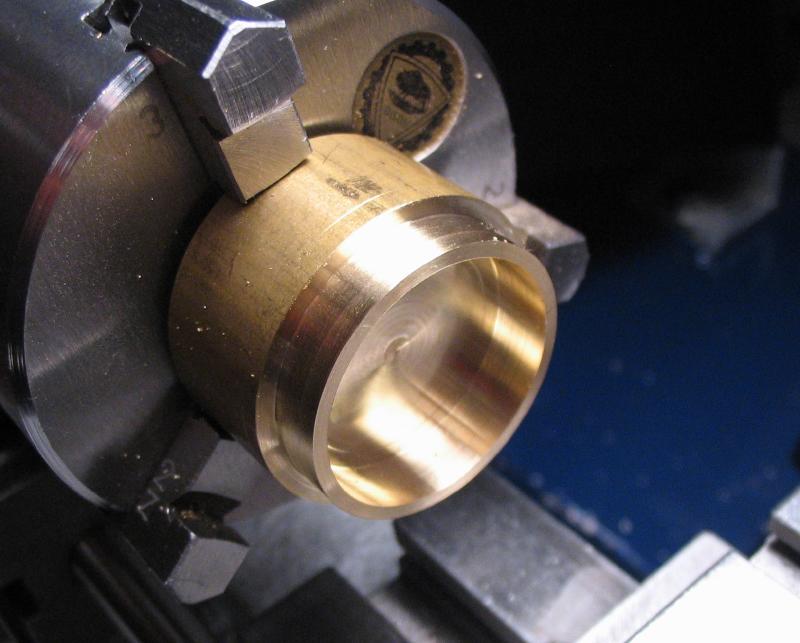
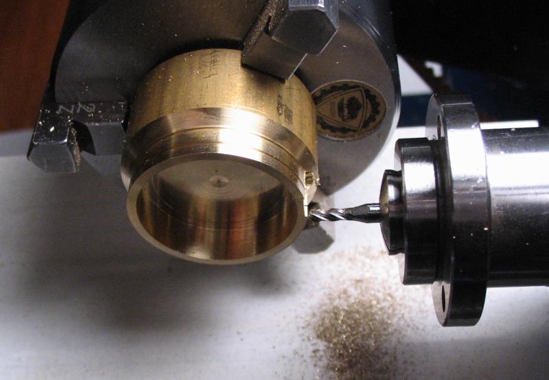
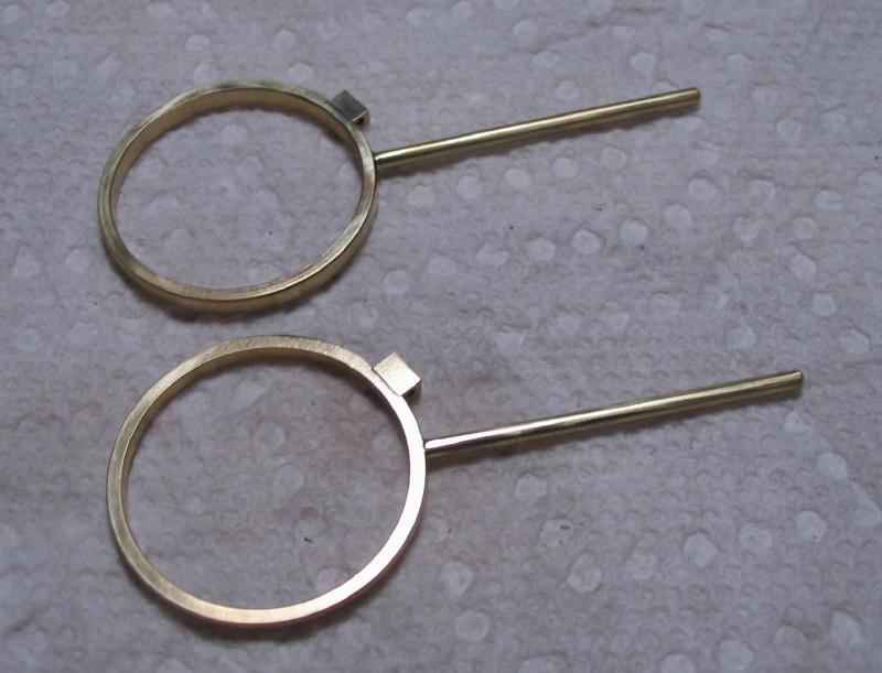
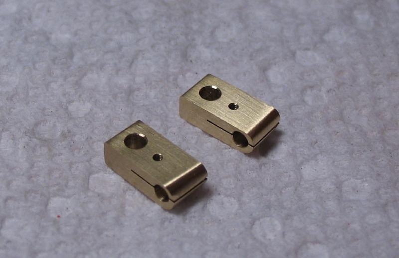
The rims for the lenses were machined from solid bar stock. It would be more economical to make a steel former of 25mm diameter and form the rims from wire stock, but I already had a short piece of 1.25" brass rod left over from another project. The rod was turned to 28mm, drilled 1/4", and bored to 25mm ID.

|
|
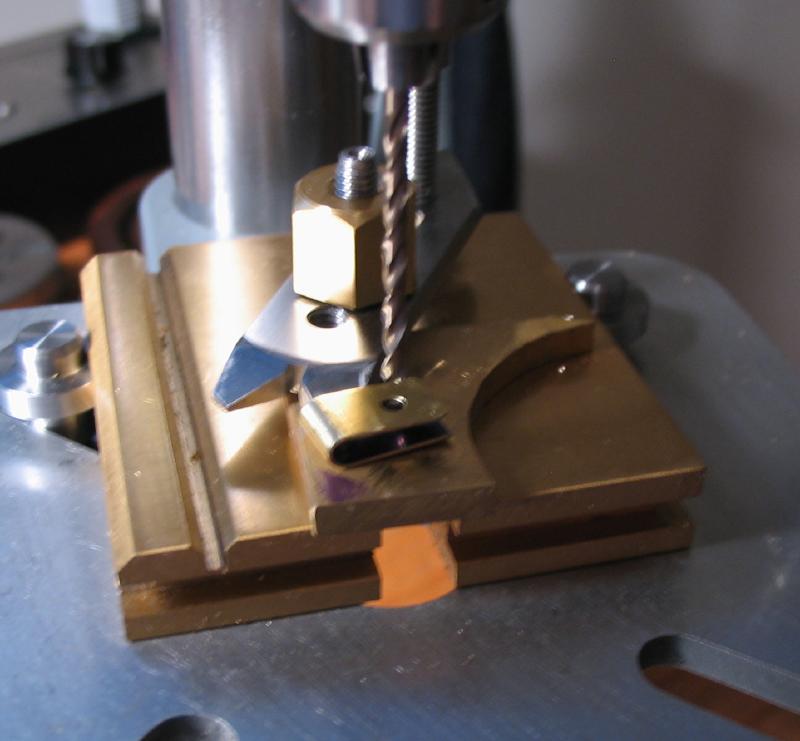
The rod was grooved at the parting positions, and lightly chamfered with a barrette needle file. The thickness of the lenses at their outer edges are 1.88 and 2.48mm (see technical drawings above). The positions for the clamps in the rims were milled using the milling spindle and a 2mm endmill. Afterward, the unfinished rims were parted off and the internal diameters chamfered using the bezel chuck and a boring bar setup at 45 degrees with the topslide.
|
|
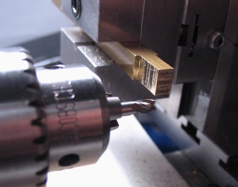
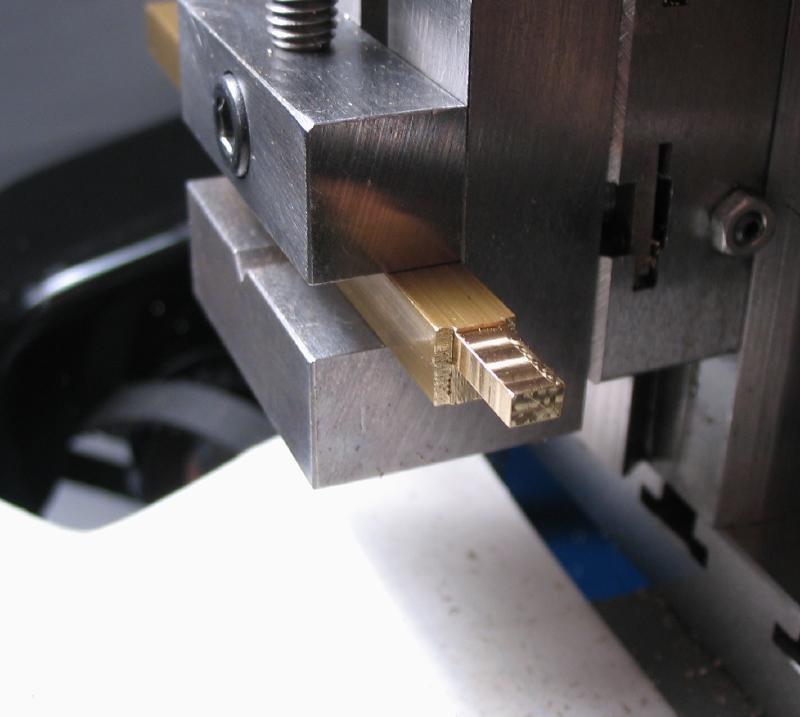
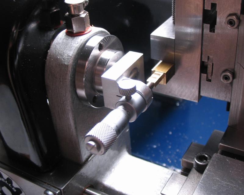
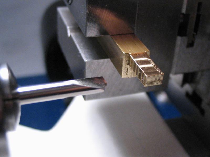
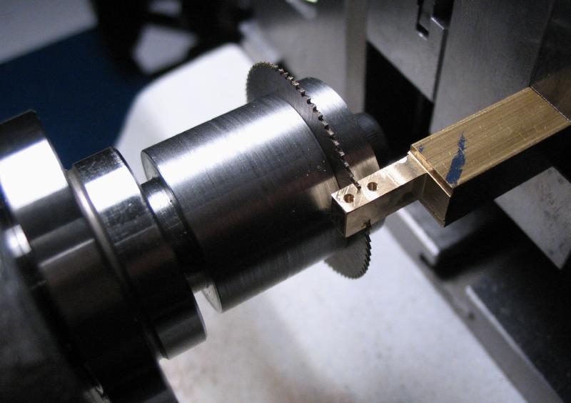
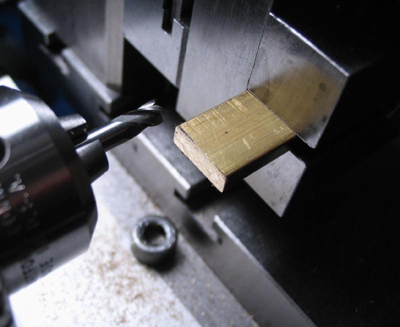
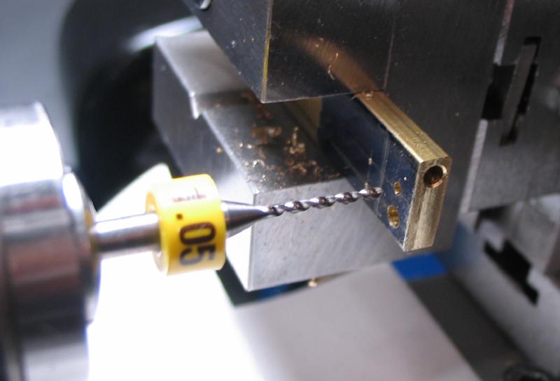
The clamps were started from 1/4" square brass bar. Although oversized, this was the closest to the desired dimensions on hand. The bar was mounted in the vise on the vertical slide and milled to 4 x 2.5mm for an excess in length.
|
|
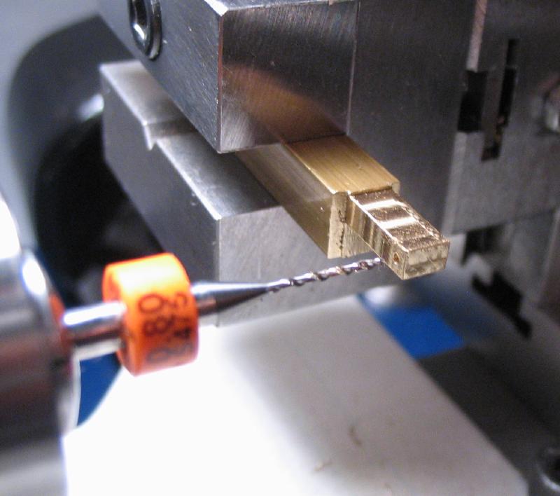
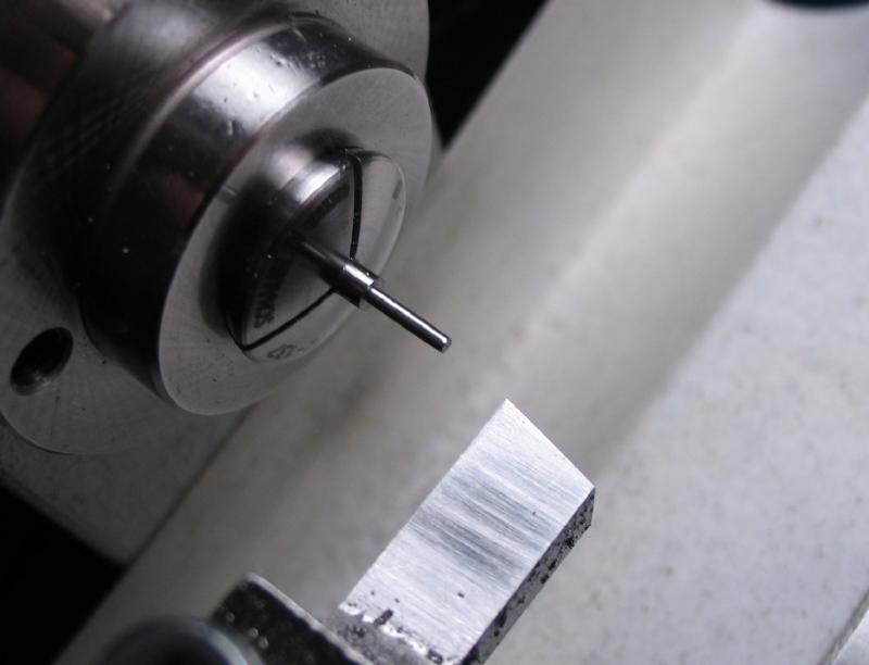
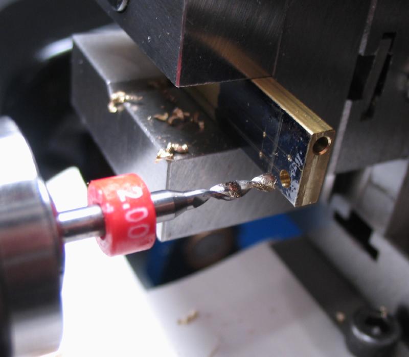
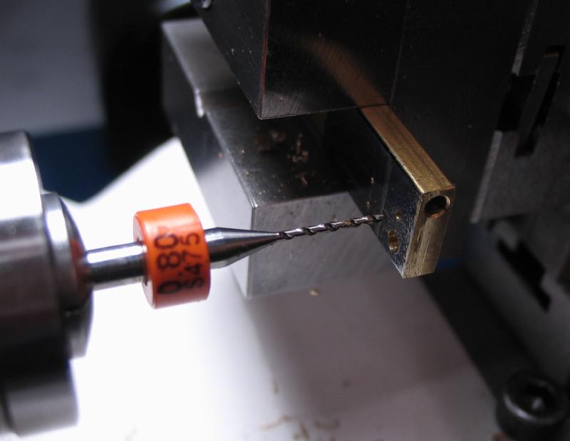
The micrometer centering tool was used to setup the work for drilling. Positions for screws were through-drilled 0.80mm and the hole enlarged to 1.05mm for half the width to pass the screw.
|
|
|

|
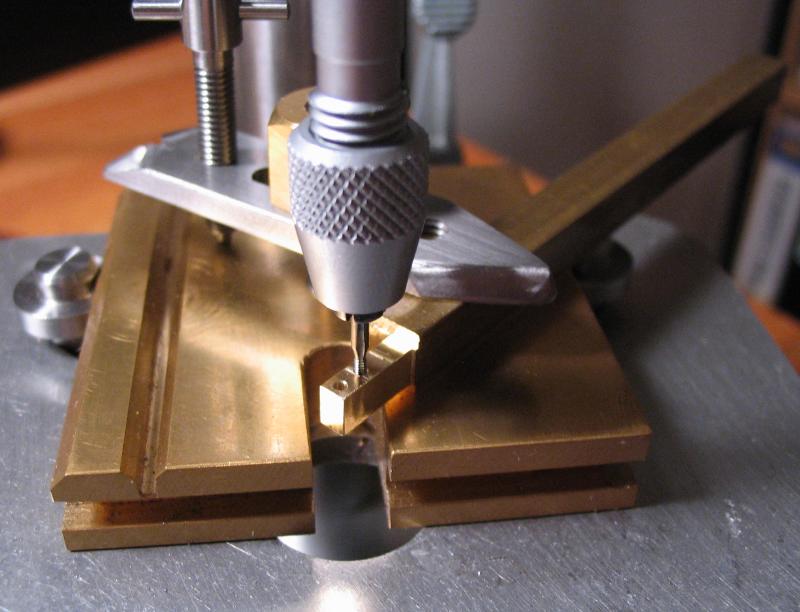
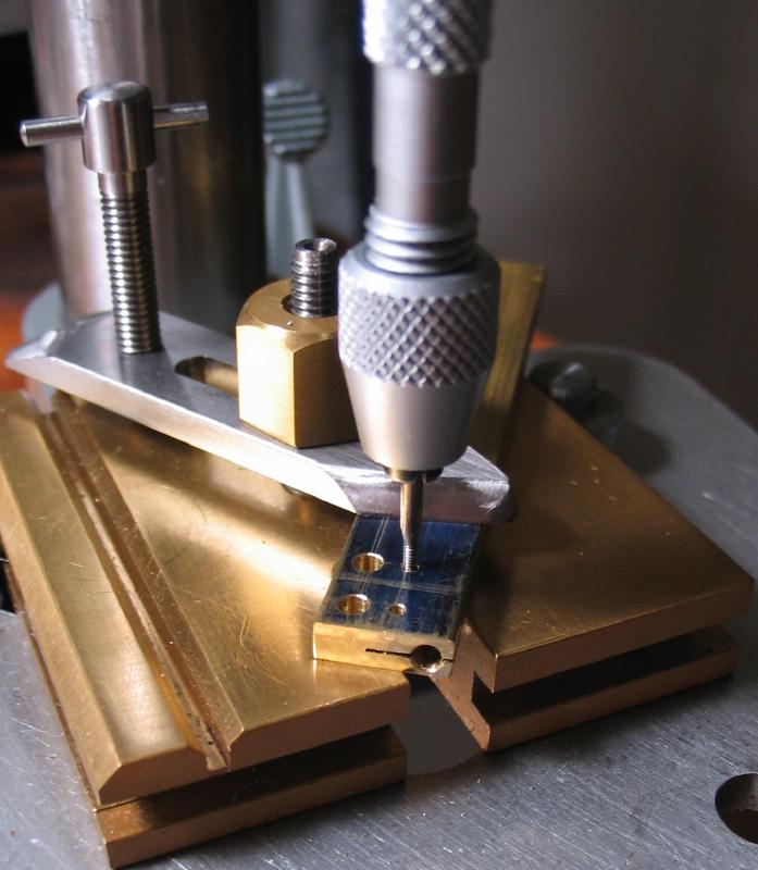
The holes were then tapped 1.0mm using the drill press for alignment.
The clamps were parted off at 2.4 and 1.8mm using a slitting saw.
|

|
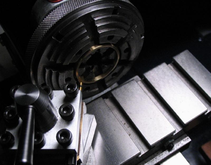
The rims were drilled 1.0mm for attaching the arms.

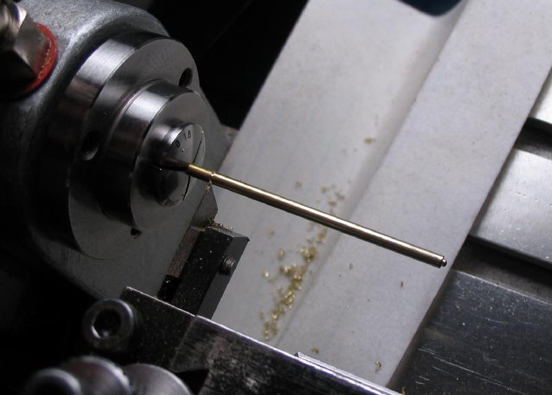
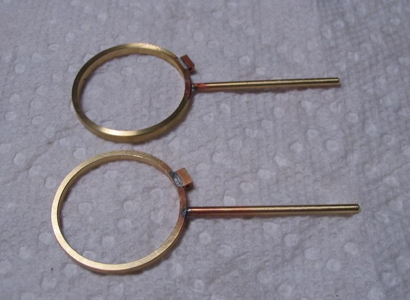
The arms were made from brass rod, using a length of an odd diameter found in the stock box, ~1.84mm (gauge 13, perhaps). A small, 1mm pip was turned to fit into the rim, and then about 35mm of length parted off and the parted end rounded over with a cup burr.
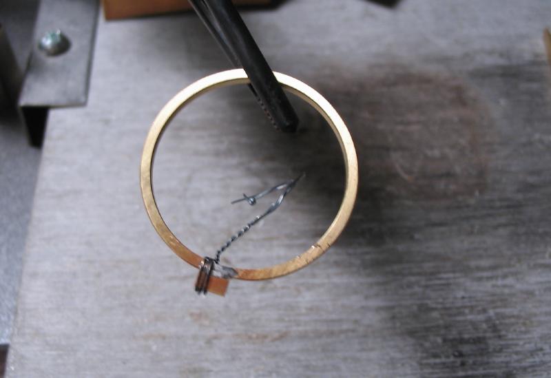
The clamps and arms were soft soldered to the rims. I used the Stay-Brite brand of solder and the included flux. It is a tin and silver alloy which melts at a relatively low temperature (430 degrees F), and is easily brought to temperature with a soldering torch. The clamps were secured with iron wire and the arms held in place with the "third" and "fourth" hands of the soldering station. After soldering, the assembly was polished to remove discoloration from the heat and flux.
|

|
|
|
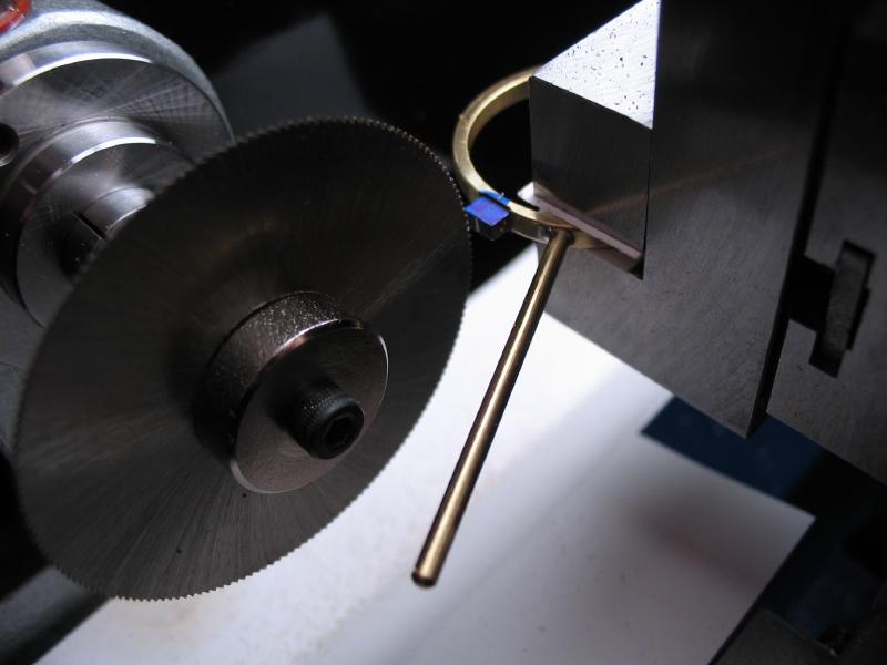
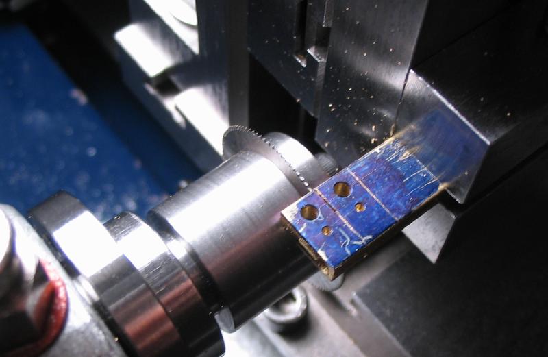
The rims were setup in the machine vise and slit open with a 0.012" saw.
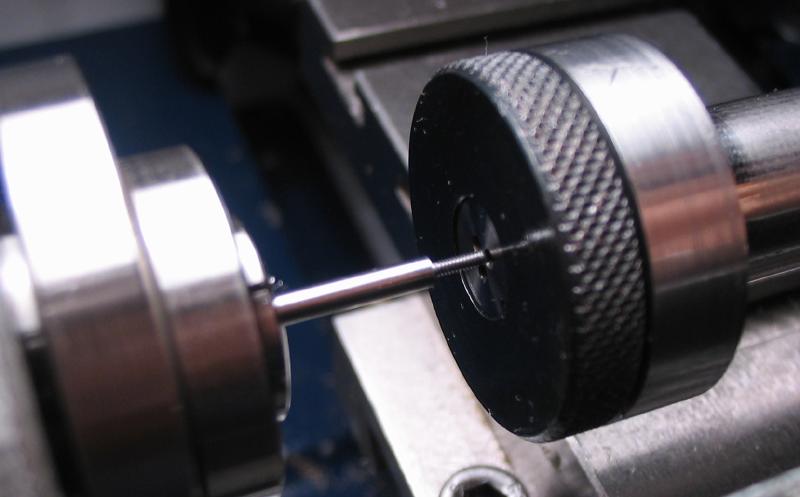
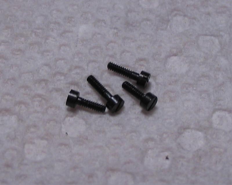
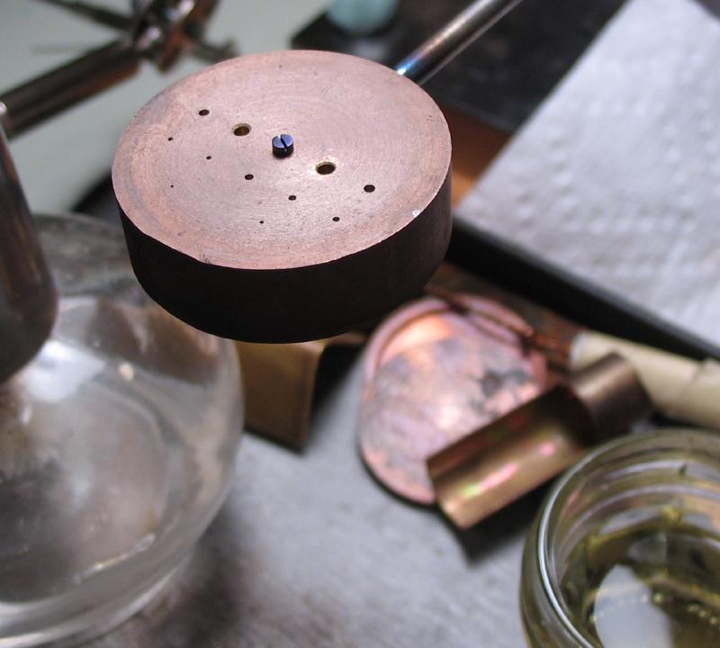
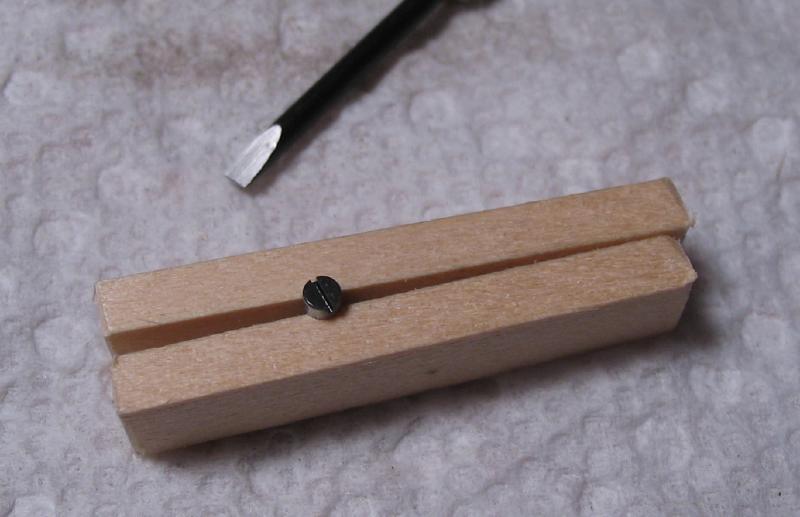
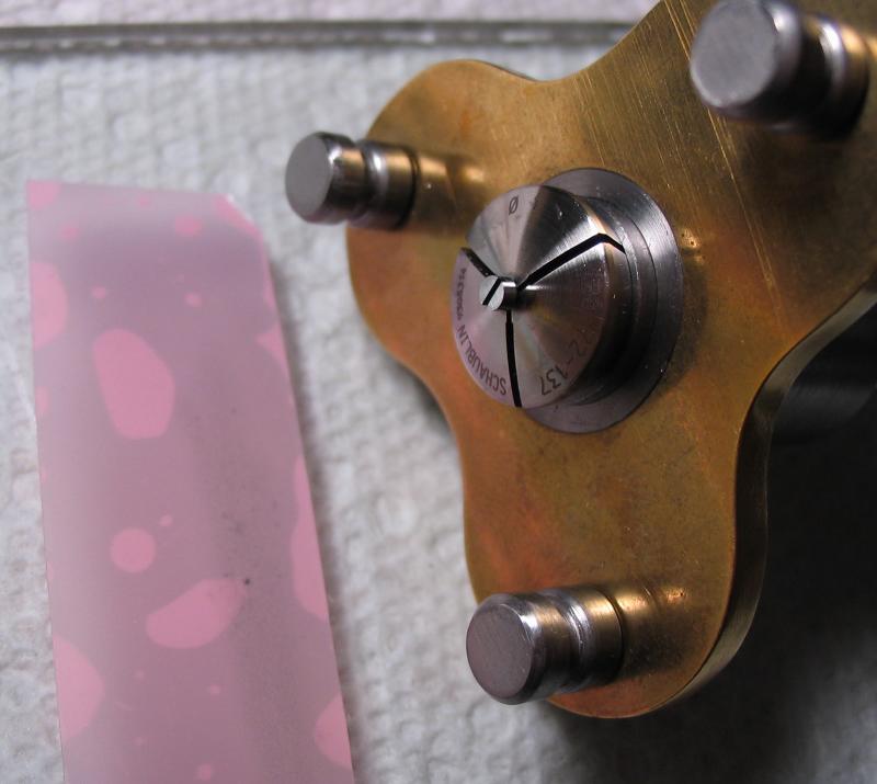
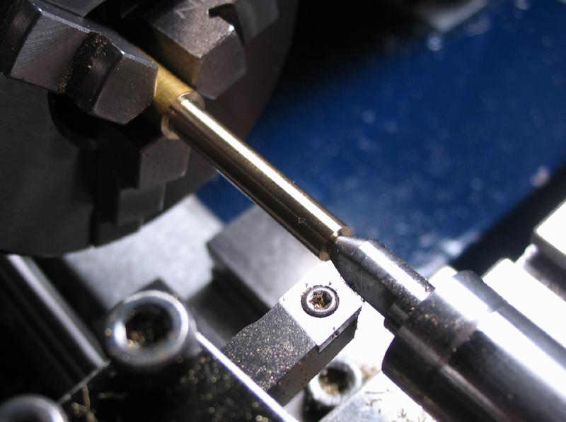
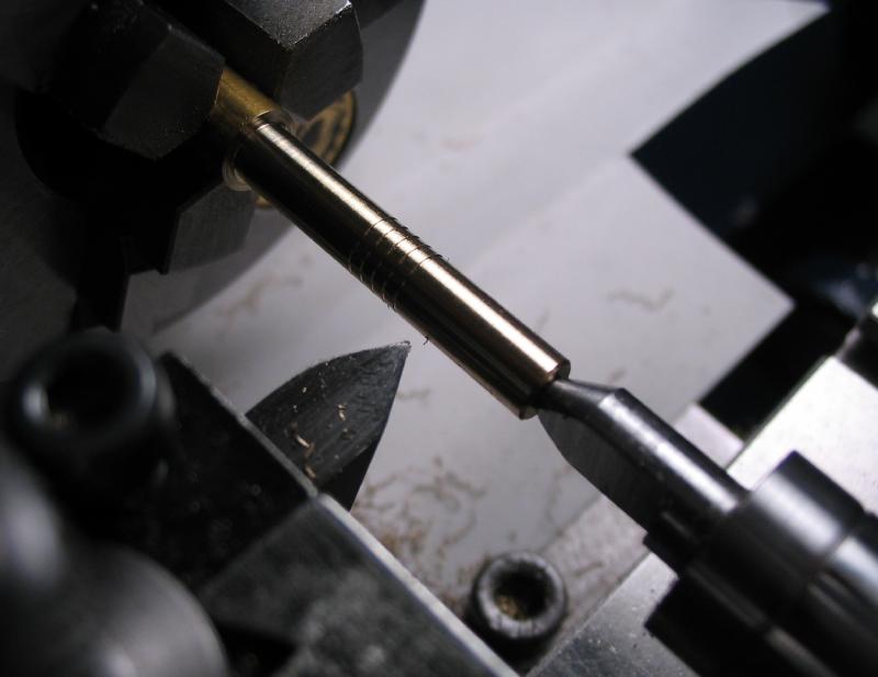
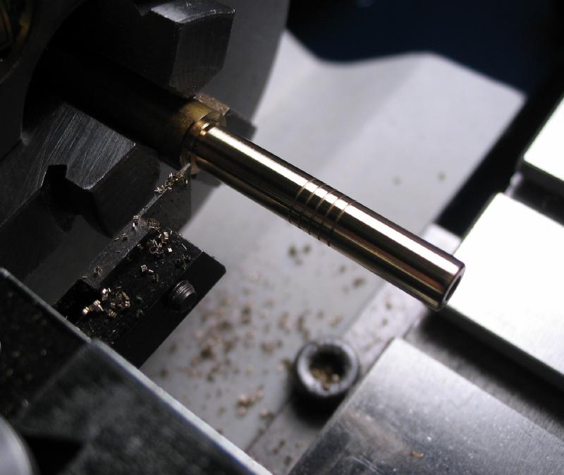
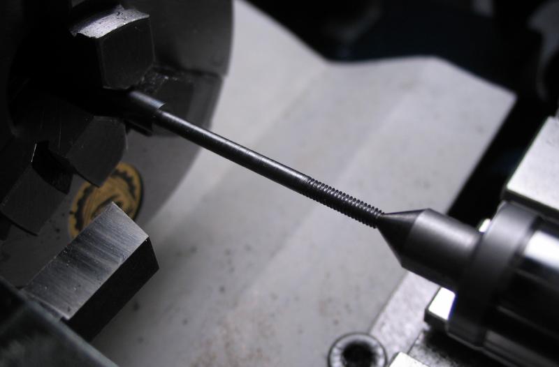
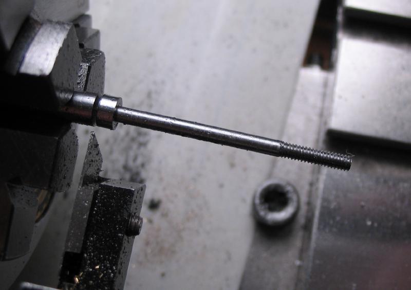
Screws for the clamps and for the mounting brackets (made below) were made. Photos of the overall screw-making process are shown below. They are made from 2mm O-1 drill rod, turned to 0.97mm for threading 1.00mm, and parted off. The parted end is coarsely polished to square up, and the slot then cut with a slitting saw on the lathe. The screw was polished up a little better, hardened, polished again, tempered, and finally polished for the last time.
Turn to 0.97mm
|
Thread 1.0mm
|

|

Part to length and then part off
|
Flattened
|
Cutting the slot
|
Hardening basket from iron wire
|
Hardened
|
Tempered
|
Threads polished between boxwood slips
|
Final polish on 3 micron paper
|
The eyeglasses can finally be fit to their rims and secured with screws.
The mounting brackets were started from 3/8" x 1/8" brass bar. The end was milled flat and then drilled 1.8mm to hold the arms above.
|

|
The positions for the locking screw and to pass the mounting post (to be made below) were laid out and drilled. The mount is 2.0mm, the locking screw is drilled 0.80mm and enlarged to 1.05mm for half the width.
|
|
|
The brackets are slotted with a 0.012" saw. The locking screw hole is then tapped 1.0mm. With the machining finished, the brackets are sawn off with a slitting saw on the lathe.

|
|
|
The brackets were filed to give a rounded edge and polished up on emery paper. The clamp allows the lens to be moved into various positions and angles.
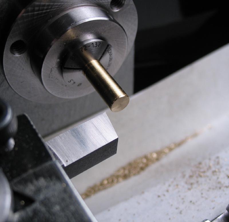
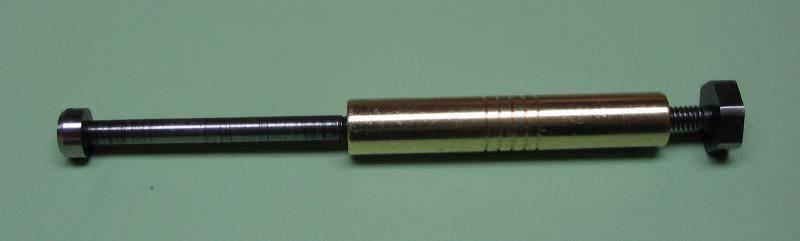
After some simple experimentation with the 100mm FL lens, it was determined that a distance of about 25mm would provide a comfortable focus. This offset will be provided by the mounting post, the post was turned from 1/4" brass rod to 4.5mm in diameter. A few decorative grooves were turned for no particular reason, and then parted off at 25mm.
|
|
|
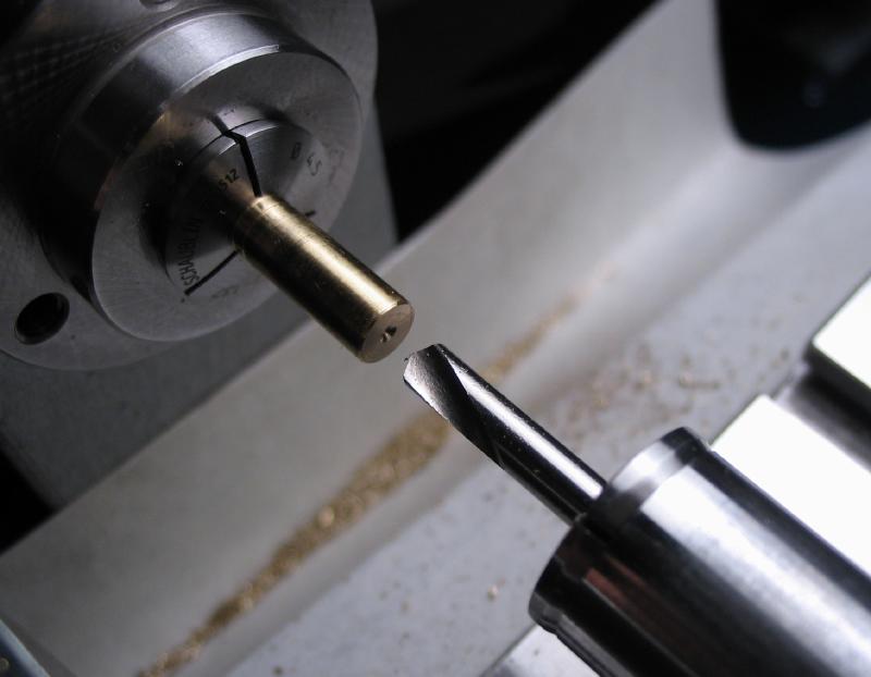
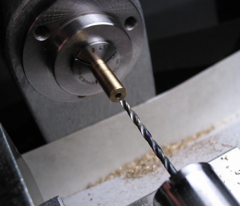
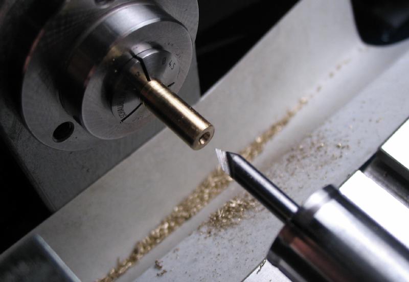
The post was mounted in a collet, faced, spot drilled, drilled 1.6mm and tapped M2 x 0.4. The rod is reversed and the process repeated, concentricity is not critical.
Face
|
Spot drill
|
Drill 1.6mm
|
Countersink
|
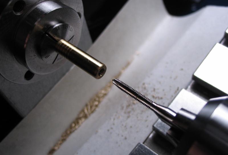
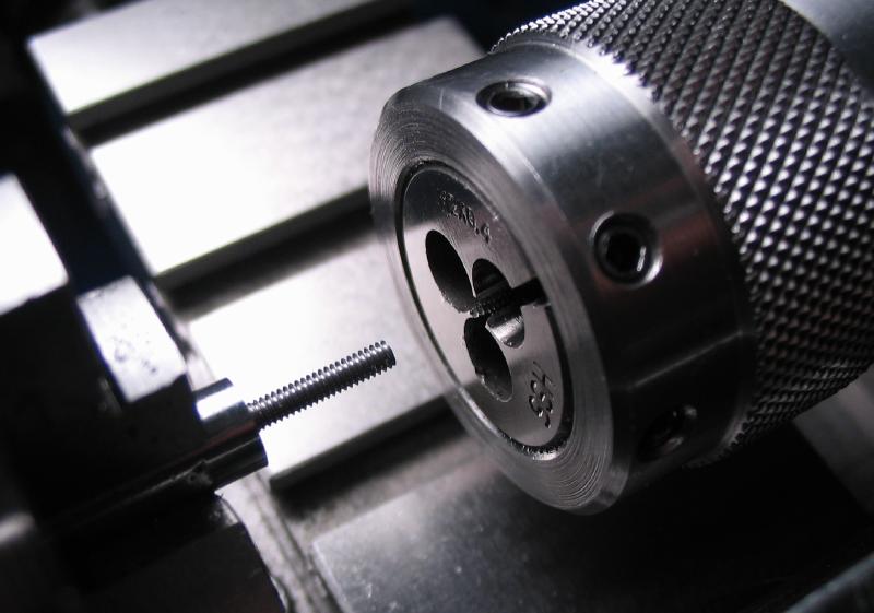
Tap M2 x 0.4
|
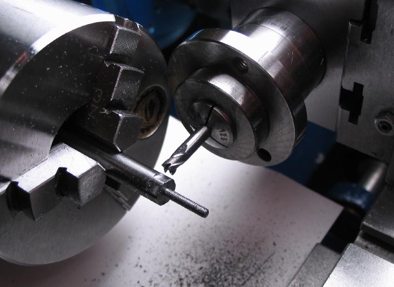
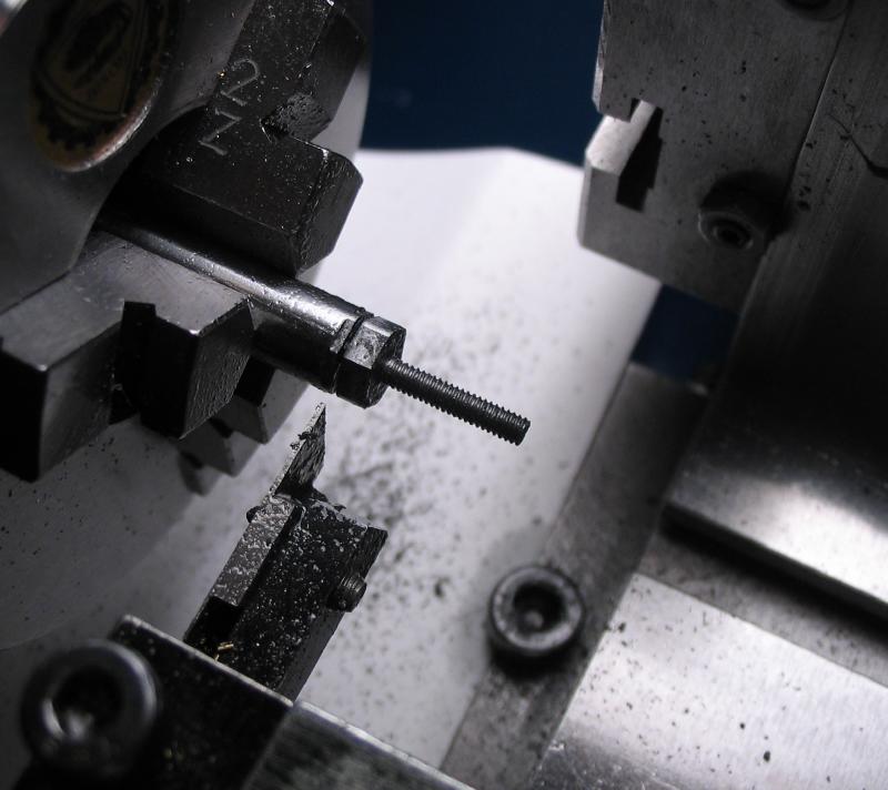
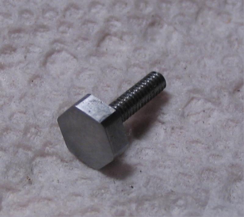
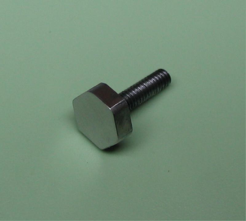
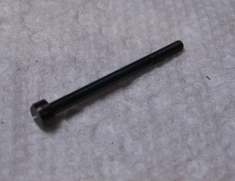
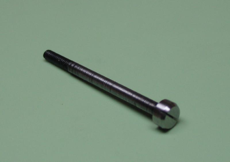
The clamping bolt was made from 6mm drill rod, turned and threaded M2x0.4. The hex head was milled to a width of 5.5mm, afterward it was parted off and polished. The bolt is hardened in oil and tempered blue, and finally polished.
|
|
|
|
|
|
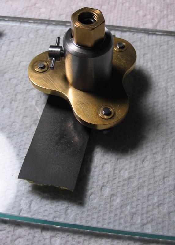
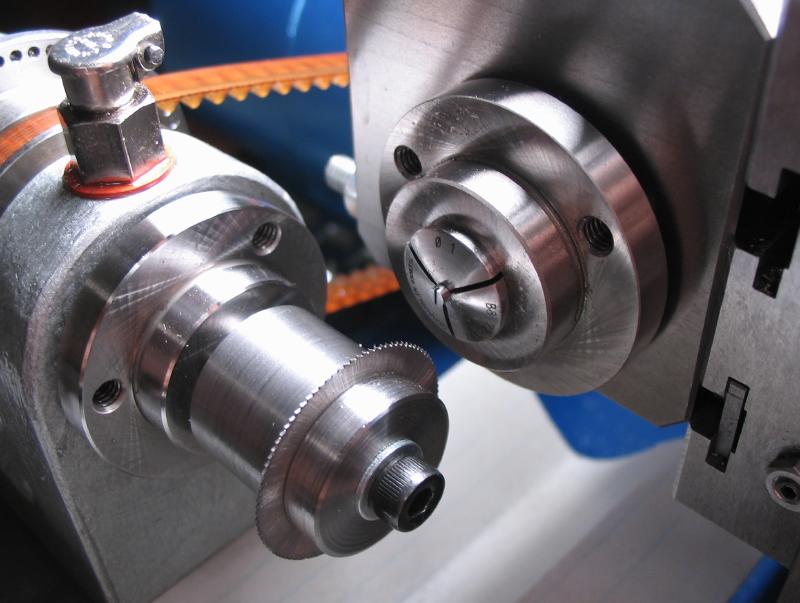
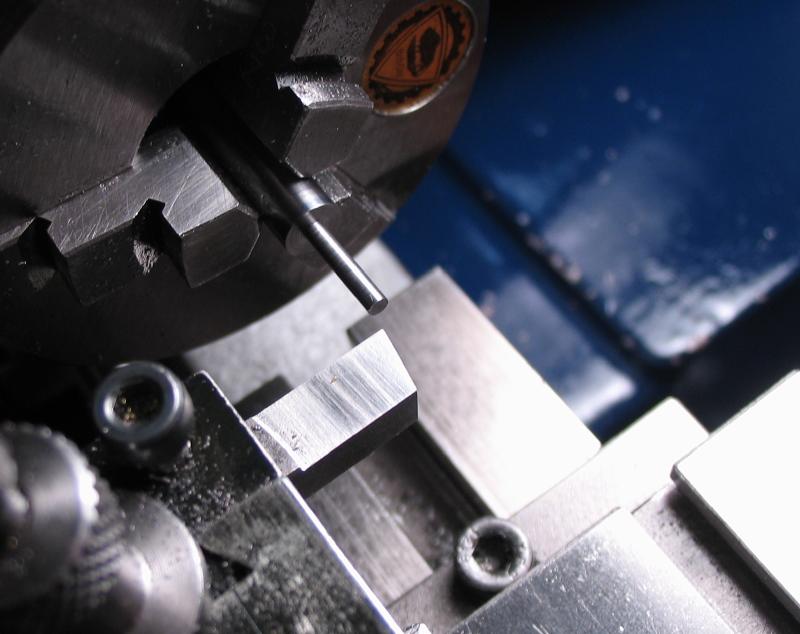
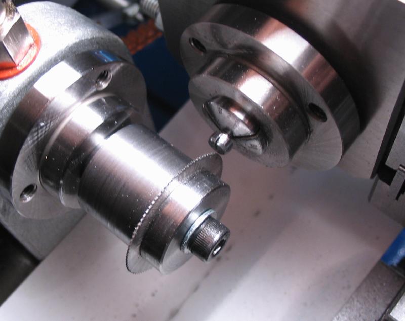
The mounting arbor for the lens frames was made from 4mm drill rod. A length of about 8mm was turned and threaded M2x0.4, and a length of 20mm turned to 2mm. The post was parted off and chamfered using the topsilde with the post held in a collet. The work was transferred to the dividing head and slotted with 0.012" saw.
|
|
|
The post was hardened and tempered and given a final polish.
|
|
|
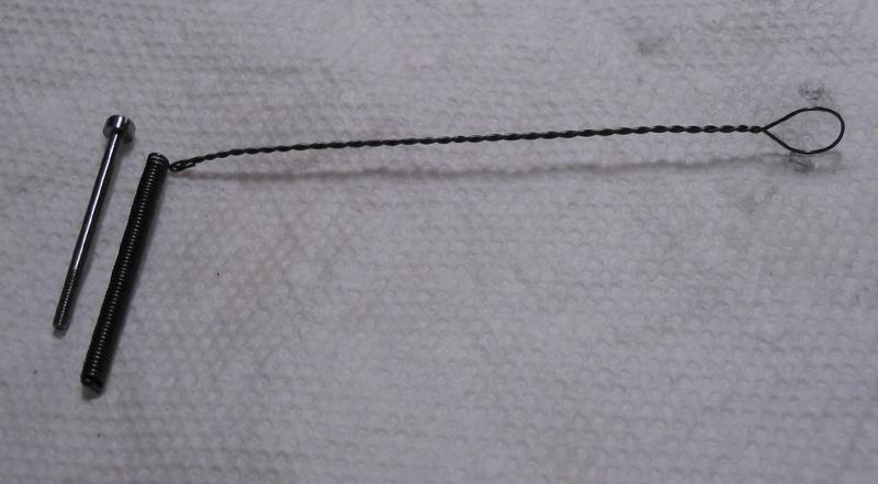
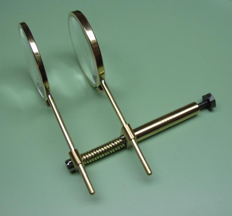
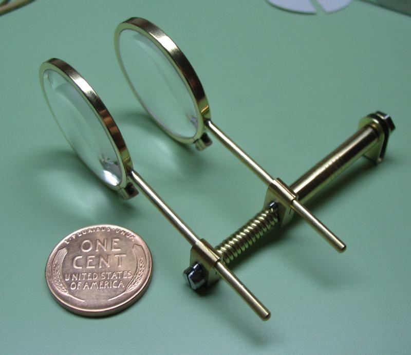
The current parts can be test fit to check progress and measure the length for the tension spring.
|
|
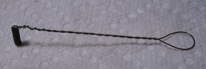
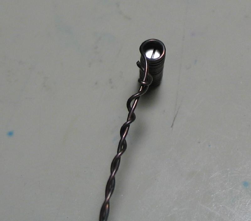
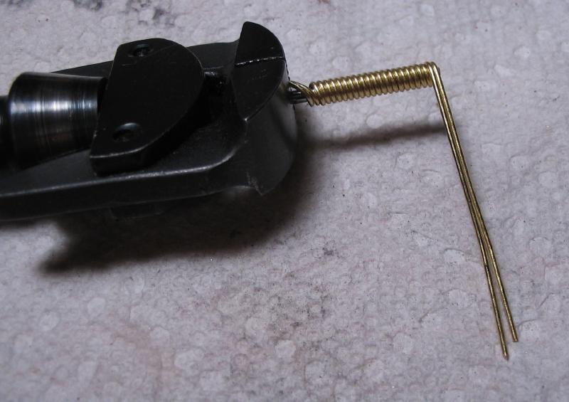
The spring was wound from two 6 inch pieces of 1/32" brass wire (a single strand should do as well) onto a piece of 2mm drill rod. The use of two wires was by accident, however, they can be 'unscrewed' slightly to provide minor adjustments in tension (i.e. length).
|
|
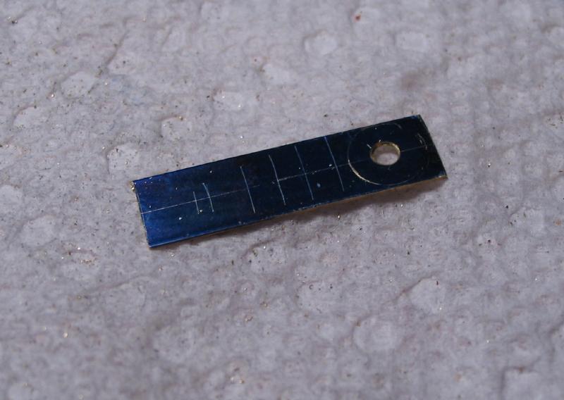
The bridge clamp was made from a length of 1/4" x 1/64" brass strip. A 2mm hole was drilled and the approximate bending dimensions were laid out. The strip of brass was bent with wire looping pliers. The second hole was drilled using the first for alignment.
|
|
|
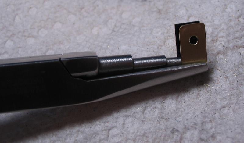
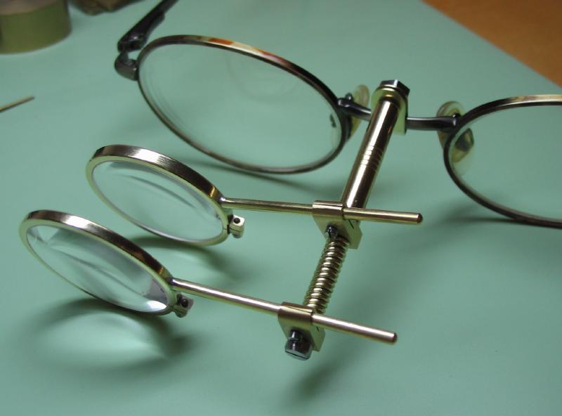
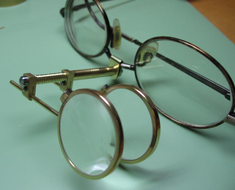
The clamp was filed to round over the ends and it simply secures on the end of the mounting post. The bolt must be removed to install onto the bridge of the eyeglass frames. Once installed the bolt is used to secure the loupe in place.
|
|
