Tailstock Die Holder
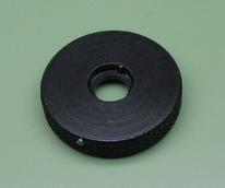
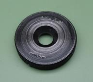
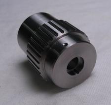
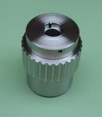
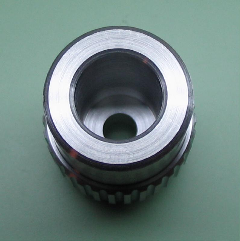
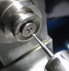
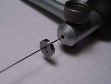
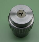
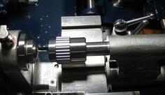
Cowells offers threading die holders that fit the tailstock quill of the lathe and fit standard-diameter dies (i.e., 13/16" and 1"). I have thought for some time that it could be useful to make a similar style holder to fit Bergeon 8mm diameter dies. Shown below is the Bergeon 30010PF, one of several types of holders that are made for their 8mm diameter dies. It is knurled on the edge and used by hand. It works well, and I usually use a drill pad in the tailstock of the lathe to help maintain uprightness while threading work held in the headstock. However, this method requires a extra hand and I have ruined work by allowing the die to lose alignment, which produces crooked threads. The Cowells die holders are bored to fit onto the tailstock quill, which provides alignment and keeps the die square to the work during use.
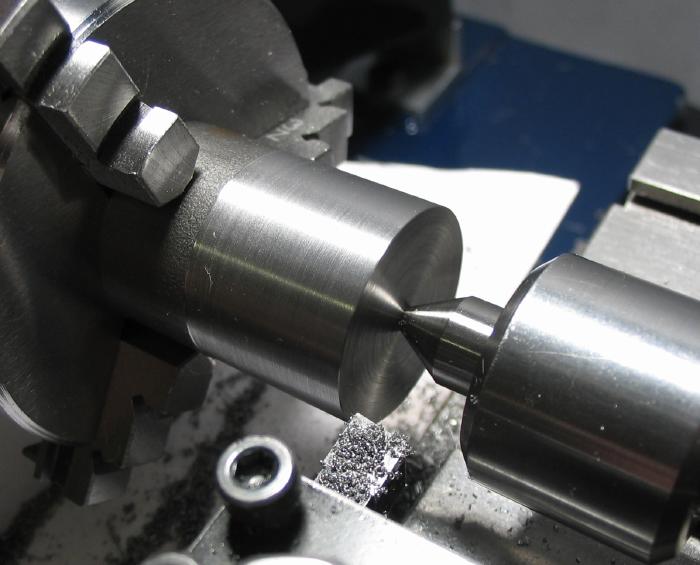
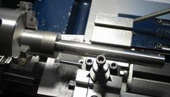
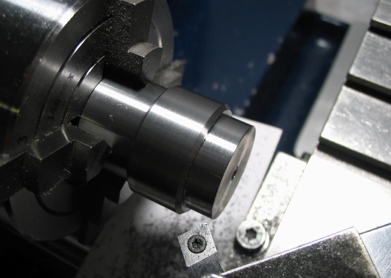
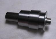
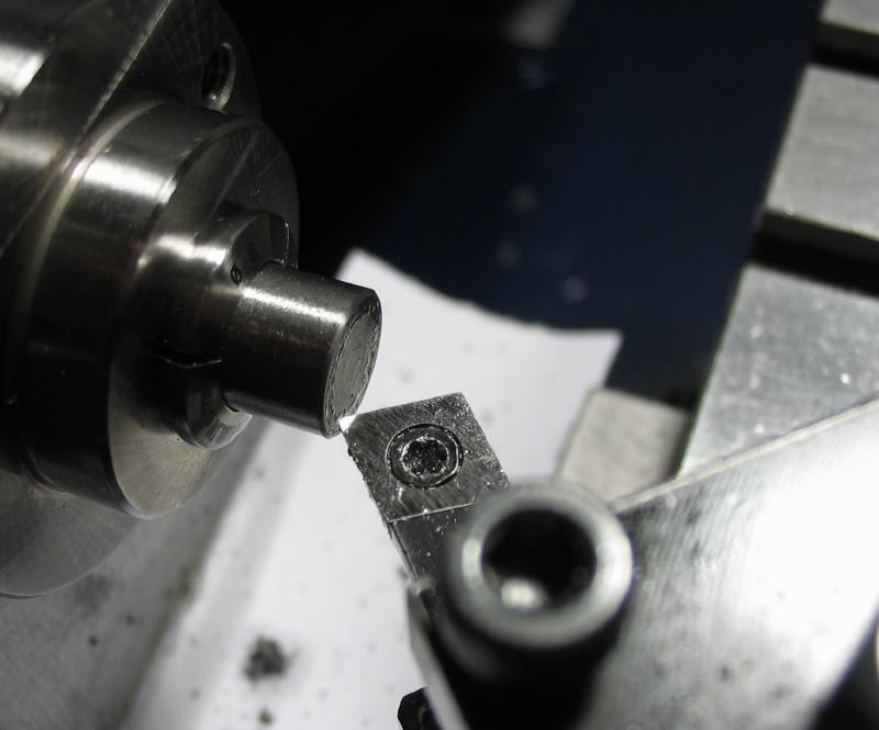
The holder was started from a roughly 35mm length of 1" diameter cold roll steel rod (12L14). The ends were significantly out of flat from hacksawing, and mounted in the 3-jaw chuck with the aid of a bump tool to coax the rod into running reasonably true. The end was faced and turned true for the available length and then reversed in the chuck for a more rigid hold. The rod was about 32mm in length after facing both ends.
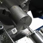
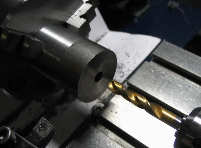
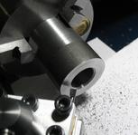
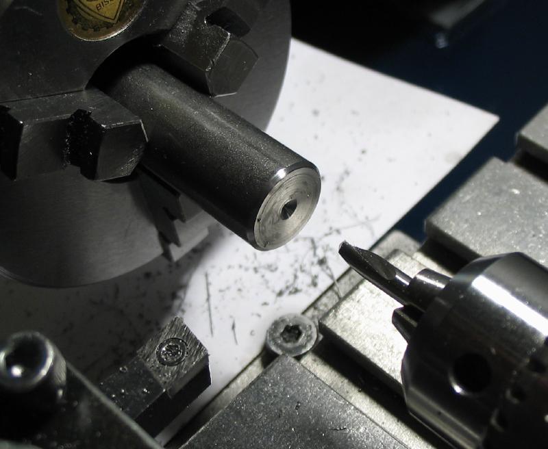
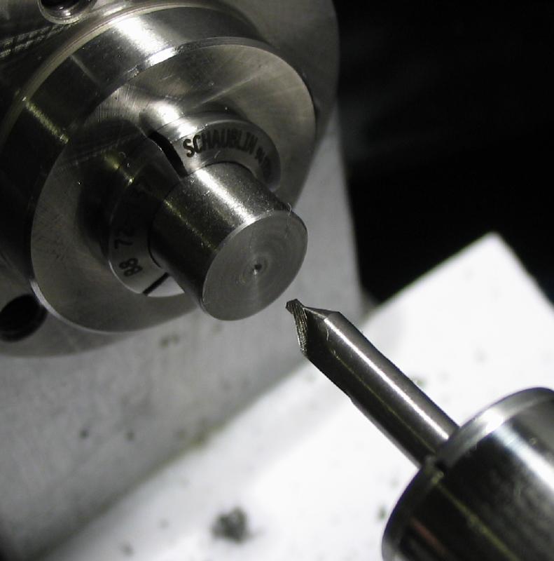
The second end was faced, spot drilled, and drilled to a depth of about 23mm. The hole was then bored open to slip fit the tailstock quill. I disassembled the tailstock to free up the quill.
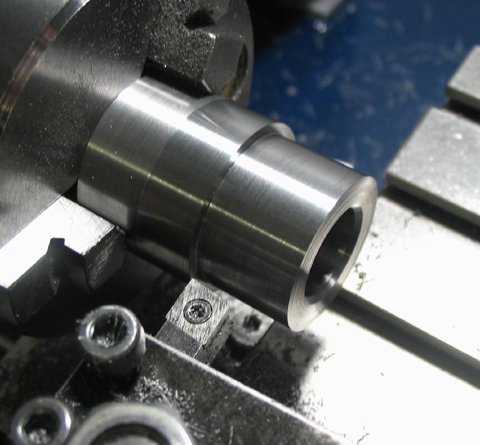
The opening was countersunk using the compound slide and boring bar, and the outside diameter reduced to 22mm for about 13mm in length. The larger diameter portion was turned true and left at about 25mm and should be concentric with the internal bore. The corners were chamfered 45 degrees.
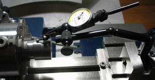
The work was reversed into a 4-jaw chuck and centered with the aid of a dial indicator against the last turned diameter. It will be important that the bores on each end be concentric, and reversing work is an easy way to foul it up.
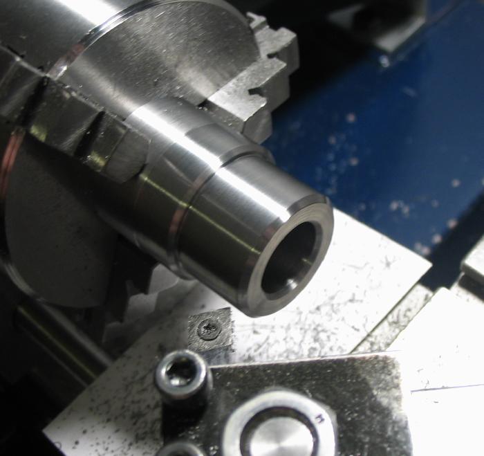
The end was turned to 21mm diameter for about 5mm length, the larger diameter, which will be become the grip area, was turned true, and the corners chamfered 45 degrees. This end was drilled through and then bored open to 6mm.
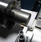
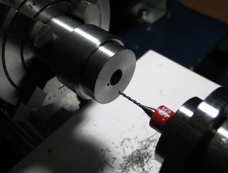
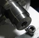
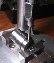
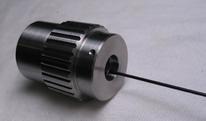
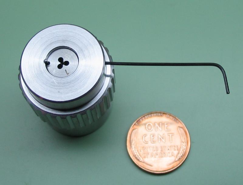
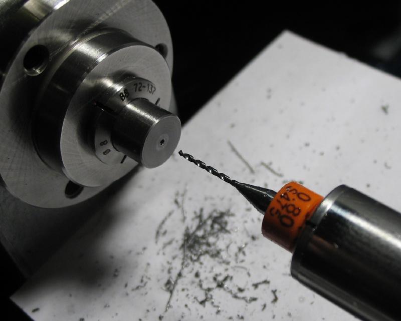
The milling spindle was set up for drilling a 0.95mm hole for a pin that mates with the notch in the dies. I used the auxiliary motor for setting this operation up. Afterward, the tool was bored open to about 8mm for a depth of 2.5mm and a die used to check the fit before the final passes of the boring tool. Afterward, the opening was lightly chamfered with the boring tool.
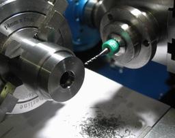
The headstock was locked back into the same position as for drilling above, but drilled for a set screw on the opposing side. I decided on #0-80 threads so that a stock, hex-drive style of set screw can be used and this was the smallest diameter I could find. The screws are 1/4" in length, which is why this end was reduced to 21mm diameter instead of 22mm. The work was moved to the drill press for tapping.
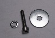
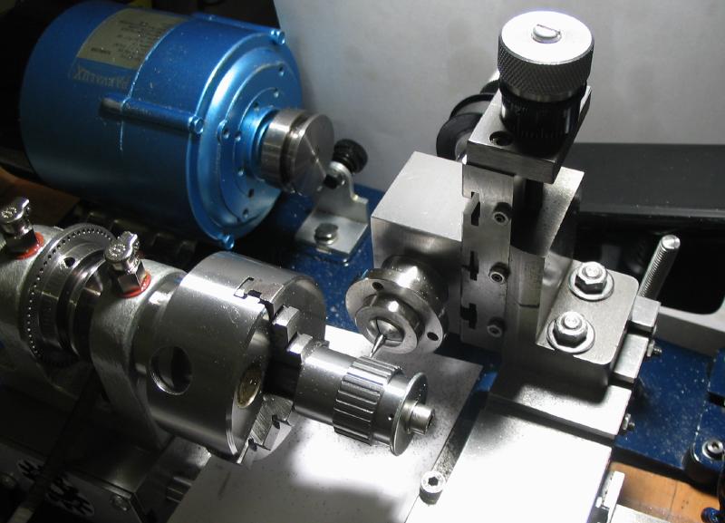
There was not quite enough clearance to mill grooves in the grip area, so first a simple mandrel was made from a length of 1/2" mild steel rod (12L14) to extend the work from the chuck. The rod was already a decent fit to the bore of the die holder and this need not be high-precision, so it only needed to be faced, chamfered, drilled and tapped for a M5 screw. Some stock hardware (M5 socket head screw and washers) was added and the assembly was ready to mount back in the lathe.
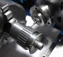
The 25mm diameter 'grip area' on the holder was given 30 grooves using a 1/16" ball end mill at a depth of 0.5mm. The headstock was indexed every other locking hole in the 60 count provided on the pulley. Since the mandrel made above has a small amount of run-out, the endmill was re-'zeroed' against the work every few positions to ensure the grooves are to the same depth.
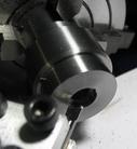
The machining should be complete at this point, and it was cleaned up prior to fitting the locking pin. The pin was made from blue tempered "pivot" steel. This piece measures 0.95mm and was fit to the hole for marking off. The pin was cut off and the ends roughly rounded over by holding it in a pinvise and using an aluminum oxide cut-off disc in the Foredom tool.
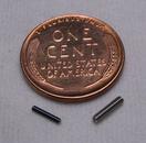
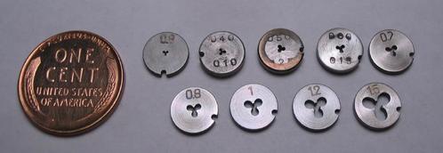
The dies shown below range from 0.3 to 1.5mm. The 0.4, 0.5, and 0.6 dies are apparently of a different vintage, perhaps, and a bit thicker and have a rougher finish than the others. This type of threading die for diameters less than 1mm seem to be getting increasingly scarce.
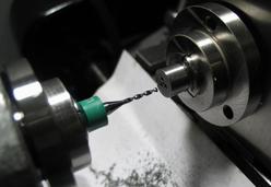
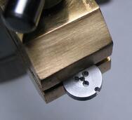
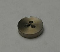
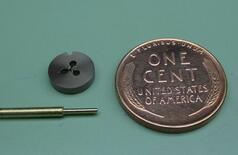
An attempt at making this type of threading die is shown below, and decided on the 1mm size. The die was started from a short length of 8mm oil hardening drill rod. The rod was held in a collet and the ends faced and lightly chamfered 45 degrees, and the rod then drilled 0.8mm.
Shown is the matching tap for the die and my basic setup for using it on the lathe. The tap is held in a pin vise and a short rod that is turned to fit a collet in the tailstock and fit into the back end of the pin vise is used to help maintain alignment. The hole in the rod was tapped, and groove milled into the side of the rod using a 1mm ball end mill.
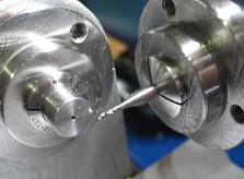
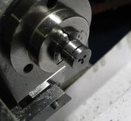
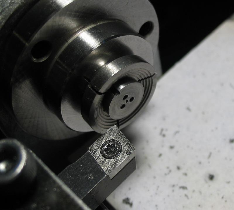
The collet and rod was moved to the dividing head and three 1.2mm relief holes drilled that are 1.2mm from center. The work was returned to the headstock and parted off at about 1.5mm thick. There was enough to part off two of them.
The parted off dies were mounted in a small step collet to face and chamfer each side, and a small setting bur using to lightly countersink the threaded hole. These burs have a 120 degree tip, if I recall correctly. A different bur was used to lightly countersink the relief holes, just to remove burs from drilling.
Slots were sawed through from each of the three relief holes into the center. I used a 2/0 sized saw, which is about 0.3mm thick.
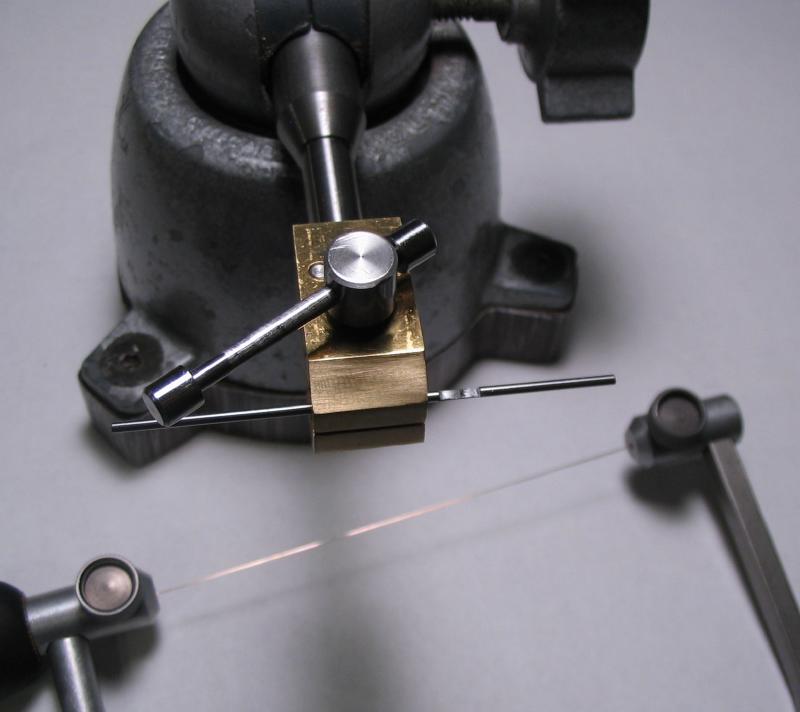
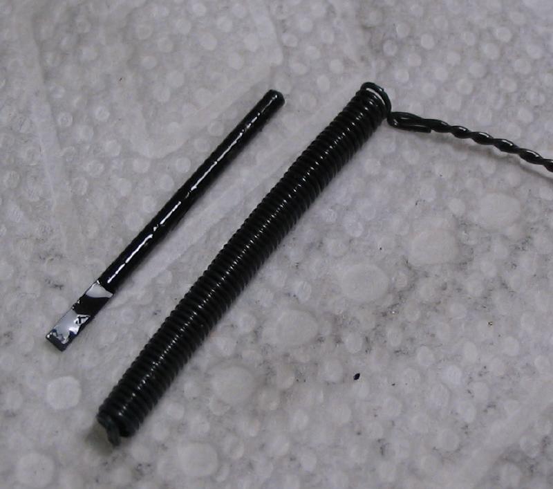
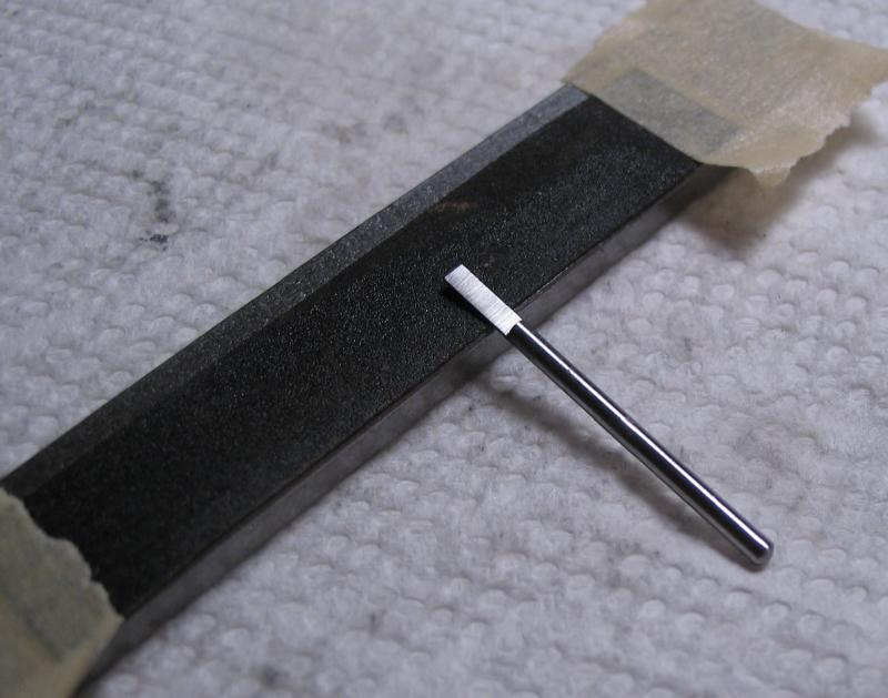
In an effort to remove any burs raised by the saw and sharpen (rather than dull) the sawed faces, a small burnisher was made from 1/16" drill rod. It was held in both the headstock and tailstock for extra rigidity, and milled on opposing sides to leave a thickness of about 0.35mm (the 2/0 saw blade measured just under 0.3mm). It was sawed off, smoothed with an Arkansas stone, and then hardened in oil. The faces were rubbed on 320 grit paper that was adhered to a piece of flat steel. The fine grain left in the hard steel from the emery paper may act as a very fine file when the burnisher is pushed through the saw slot of the die. Whether this will have much effect is hard to say, but was my best idea for sharpening in this very tight spot.
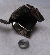
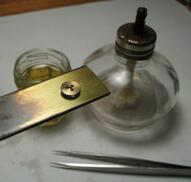
The die was sealed in stainless steel foil for hardening, and came out afterward with almost no oxidation. It was then tempered to about a straw color using a piece of brass strip with alcohol lamp underneath.
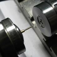
The die was tried out on a piece of 1/16" brass rod that was turned down to 0.97mm and the die mounted in the holder, which was mounted on the tailstock. The die was a little hard to get started, but the resulting threads didn't seem too bad. There was a slight negative taper to the turned section of brass.

