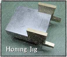
Honing Jig
A jig for honing lathe tools is described by John Wilding in at least two of his books. Details are provided in "Using the Small Lathe" and an enhanced version appears in "Tools for the Clockmaker and Repairer." The jig provides a surface to place the tool, or its holder, and a pair of guides to place a stone at a set angle. The angle suggested in "Using the Small Lathe" is 84 degrees, which will hone a 6 degree clearance on the tool. This is a deliberately small angle so that only the cutting edge is honed.
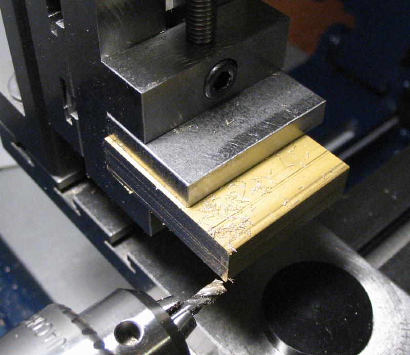
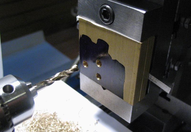
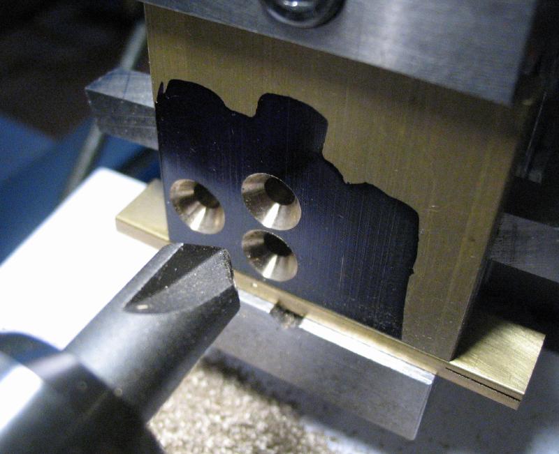
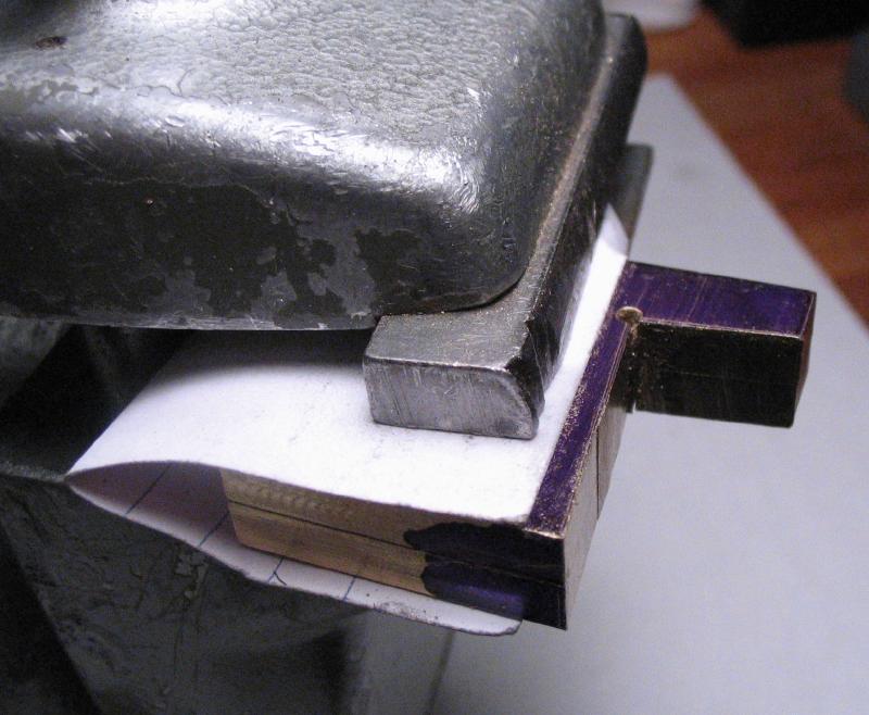
The guides were started first from a pair of brass plates. Two 1.25" lengths of 3/16" x 1.5" brass plate (360) were sawed off and the ends squared up. The plates were kept together and drilled to clear #6-32 threads in three locations. The plates were separated and the outer faces countersunk 82 degrees for matching screw heads (there was some tool chatter with the countersink which is visible in the photo).
|
|
|
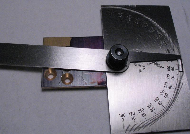
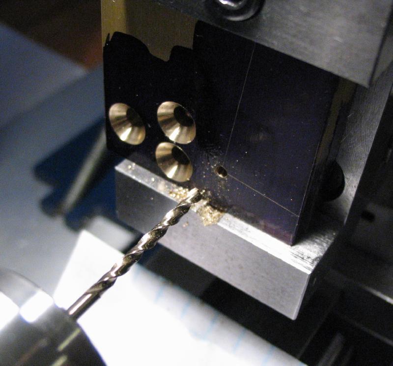
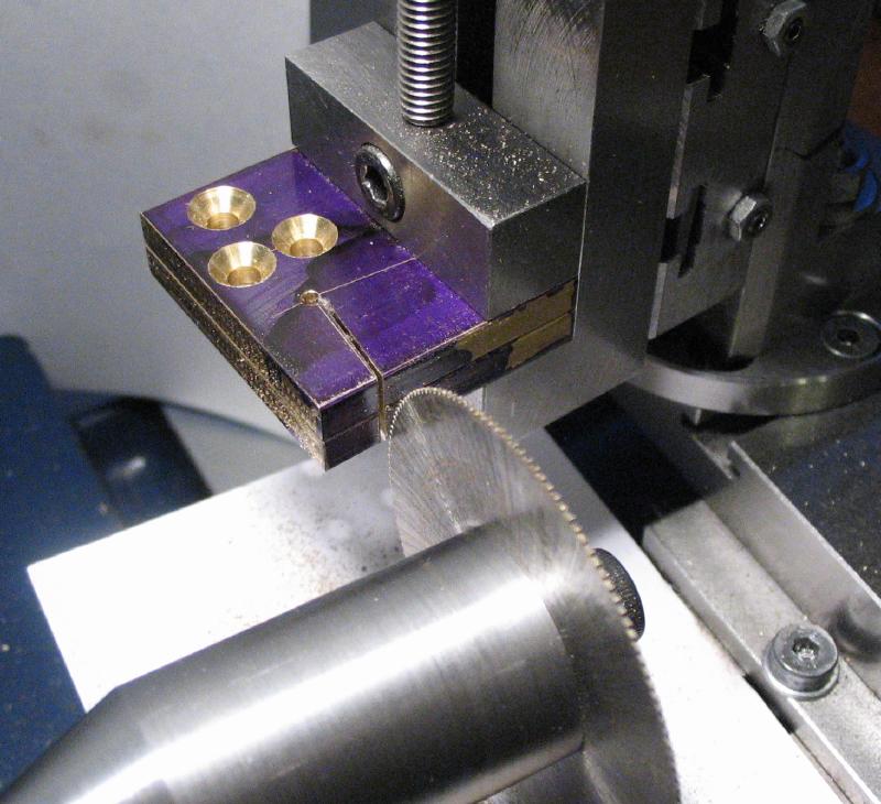
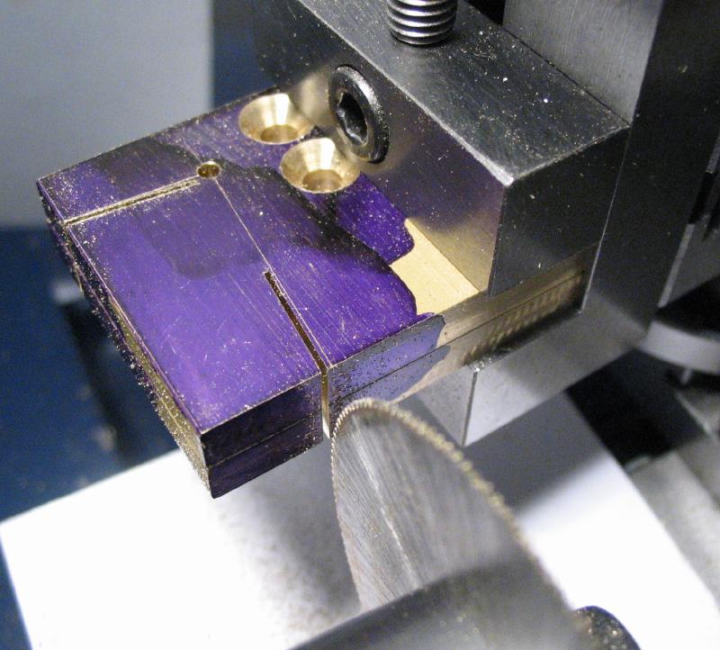
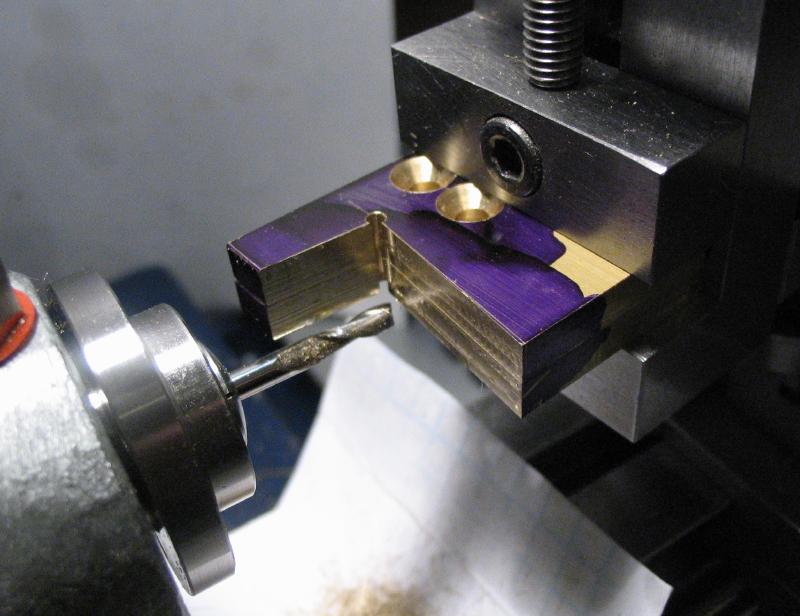
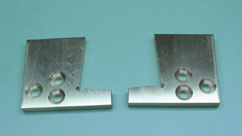
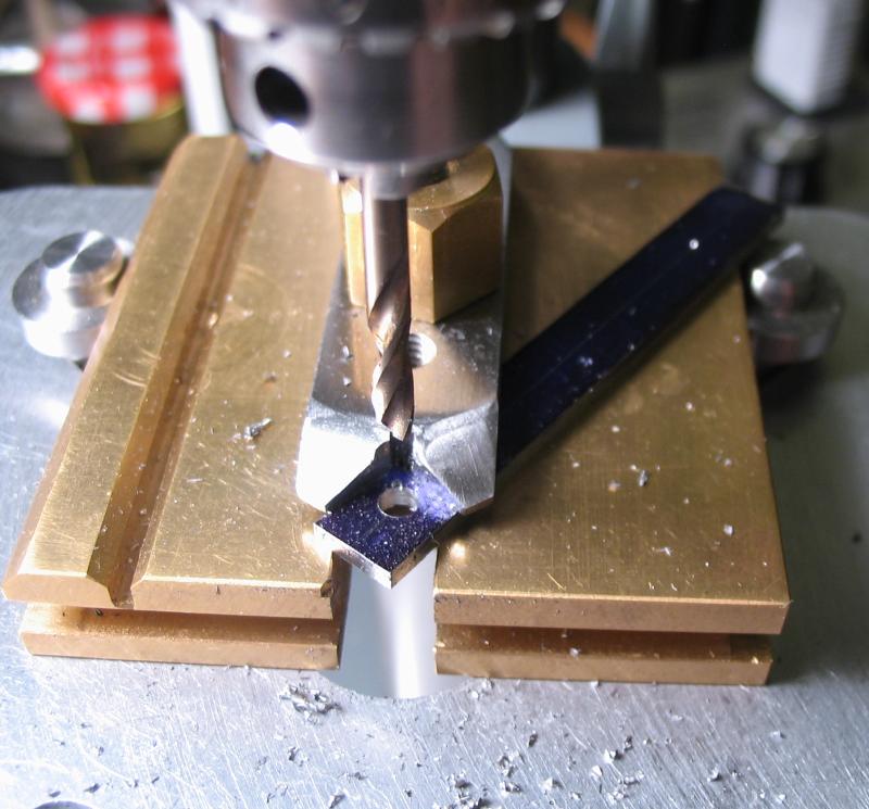
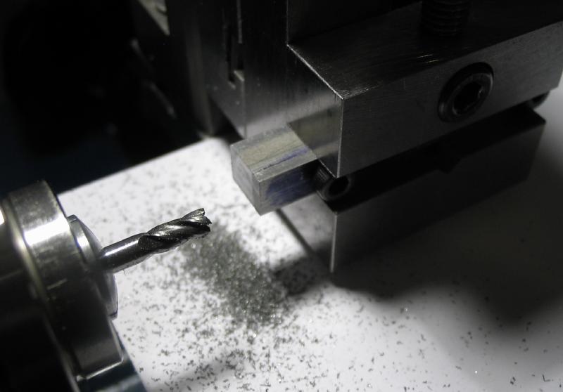
The 84 degree faces were laid out using a protractor. A 2mm relief hole was drilled in the corner and a slotting saw used to cut out the bulk of the waste. The saw was not quite large enough, so it was finished with a jewelers saw. The faces needed to be refinished with an endmill.
|
|
|
|
|
|
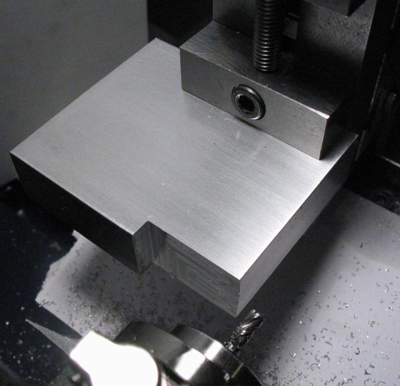
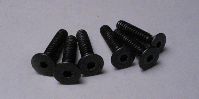
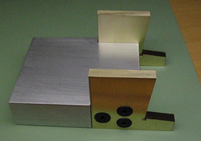
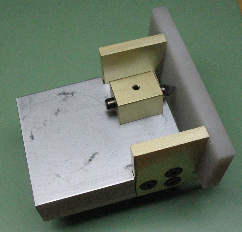
The base was started from about 2.25" length of 5/8" x 2" aluminum bar (6160 grade). The ends were squared reasonably with a large file and recesses for the guides were milled out and the screw positions drilled and tapped #6-32. The screws are stock 'black oxide alloy steel' screws with countersunk heads and hex drive.
|
|
|
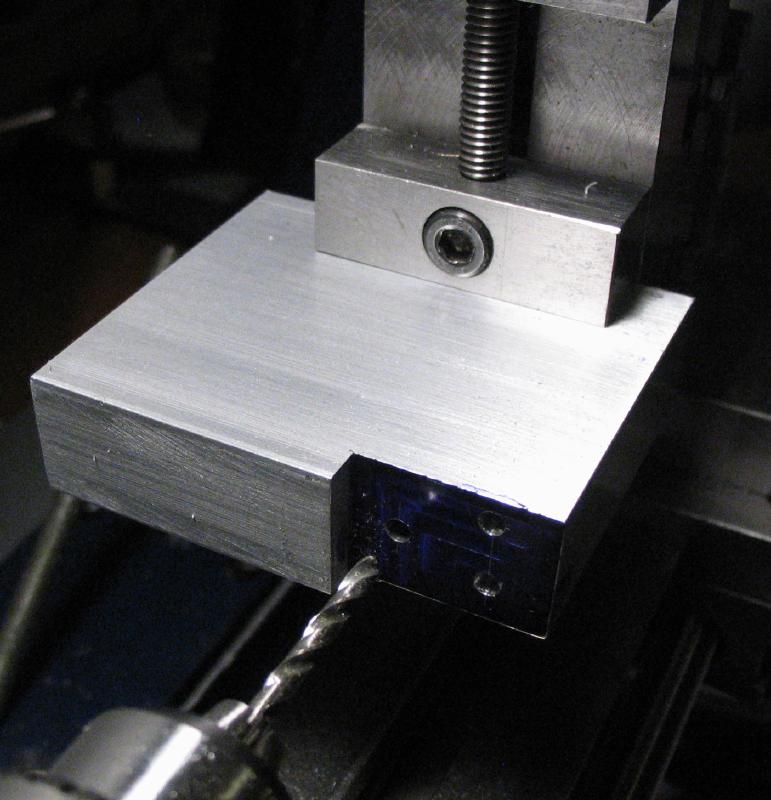
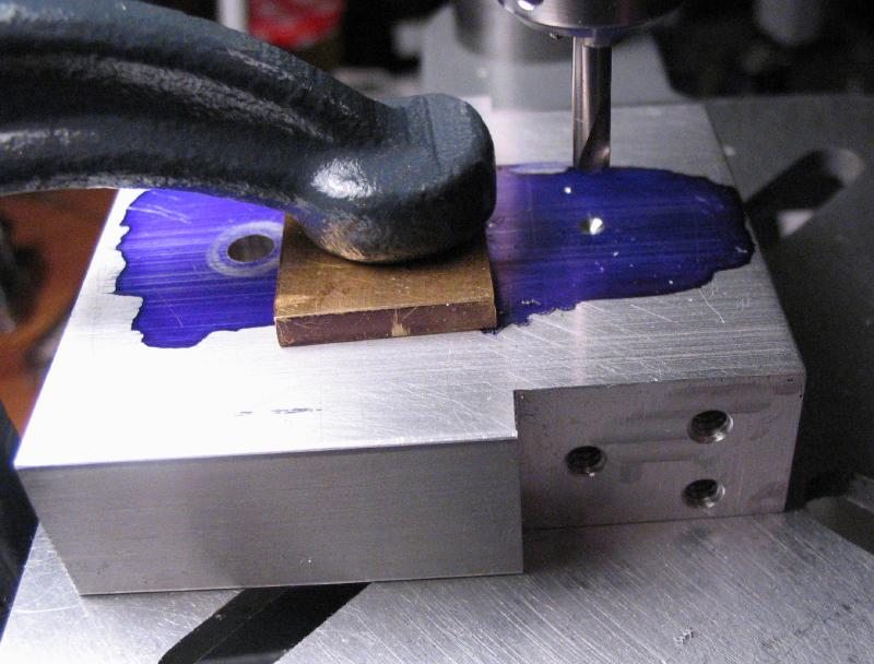
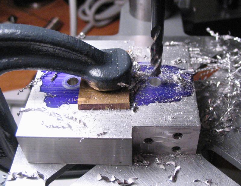
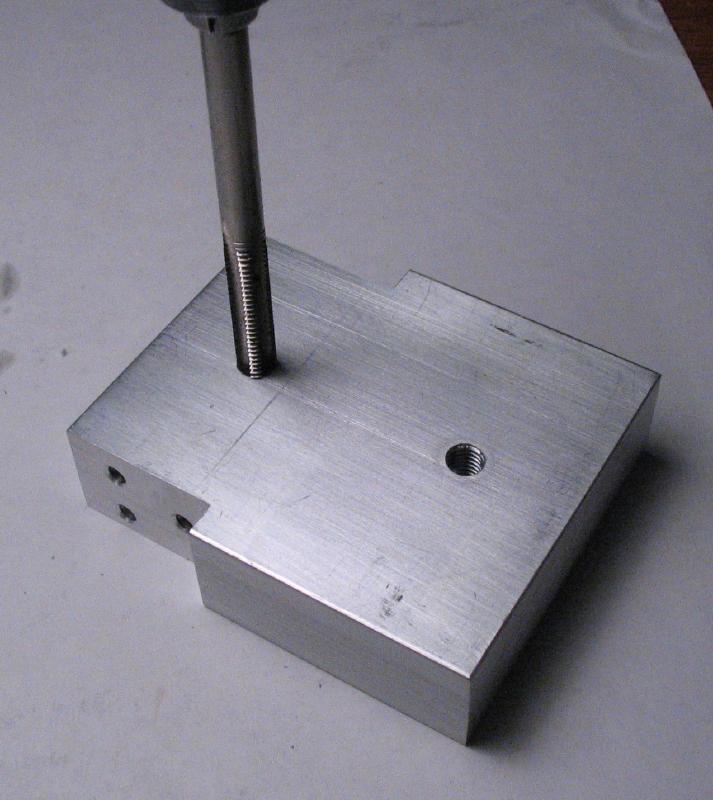
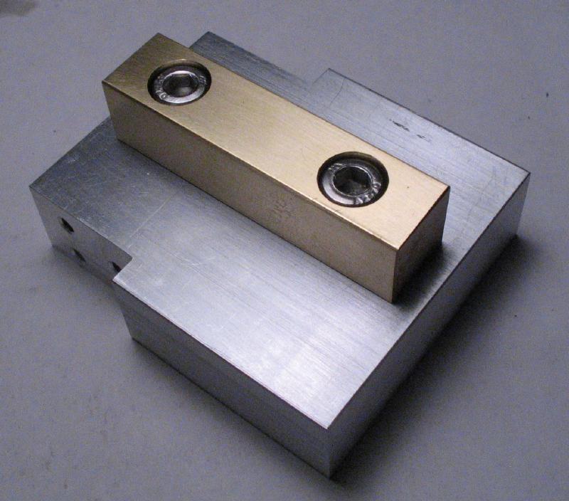
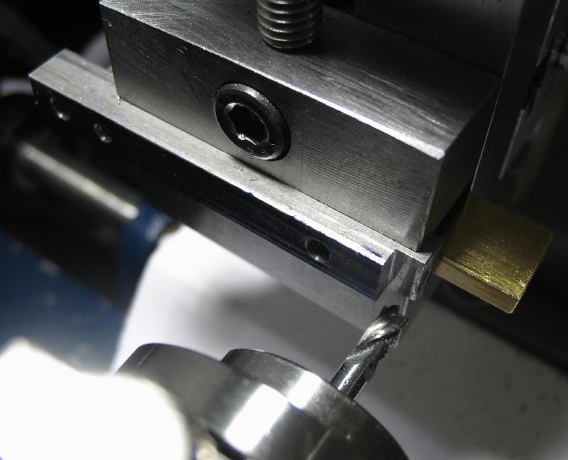
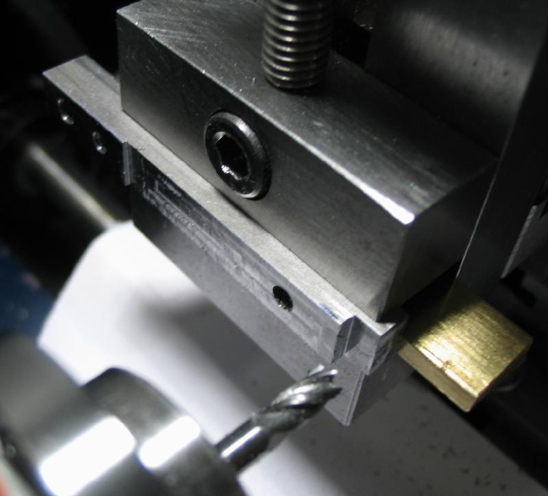
A bar was added to the bottom of the jig so that it can be held in a small vise. Two 4.2mm holes were drilled on center line and about 30mm apart, and then tapped M5x0.8.
|
|
|
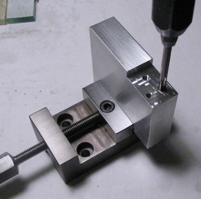
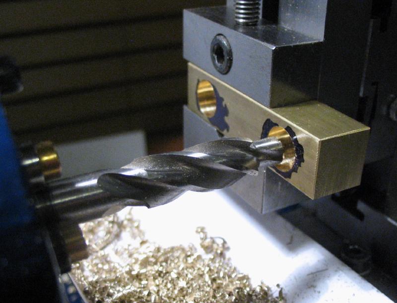
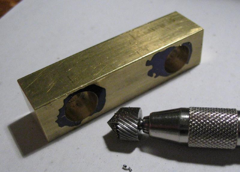
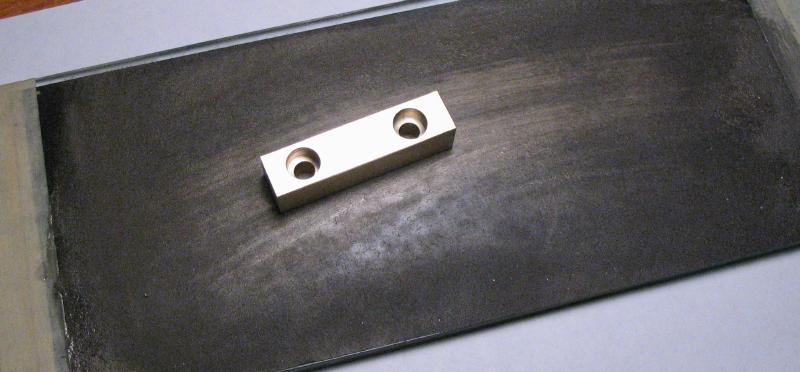
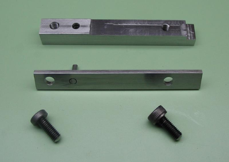
A 2" length of 1/2" square brass bar was drilled 5.5mm and the holes then counterbored for M5 socket head screws. The surface was cleaned up on 400 grit emery paper.

|
|
|
|
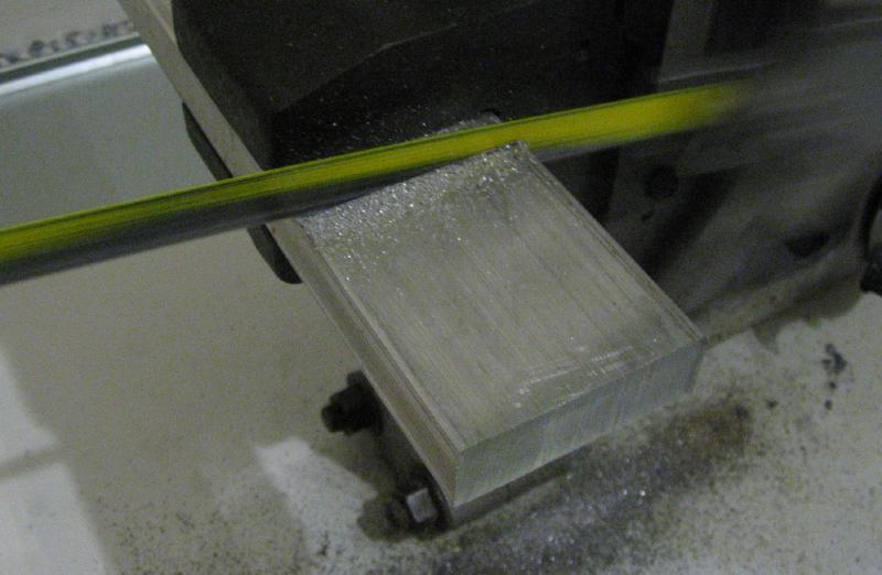
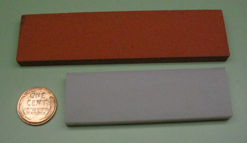
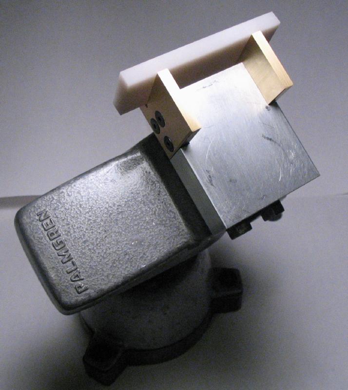
Below are a couple stones that are a convenient size to use with this jig. The top stone is a Norton fine India oil stone (model FB-14) and the lower is a "translucent" Arkansas "pocket" stone from Dan's Whetstone. The jig is shown held in an adjustable position vise, which seemed to be helpful in keeping the stone in place and to see what one is doing. Also shown is the first task that I had in mind for the tool, which involved grinding a small radius on the tip of a fly cutter bit; the jig is shown sitting on the benchtop since it was easier to photograph.
|
|
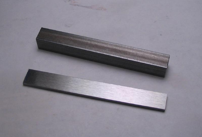
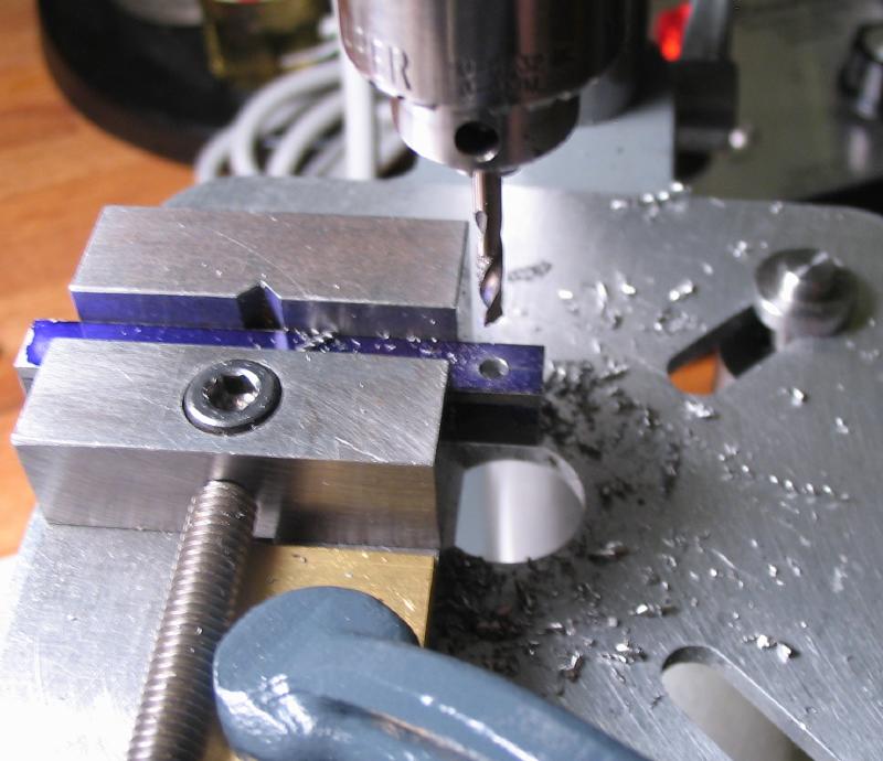
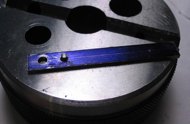
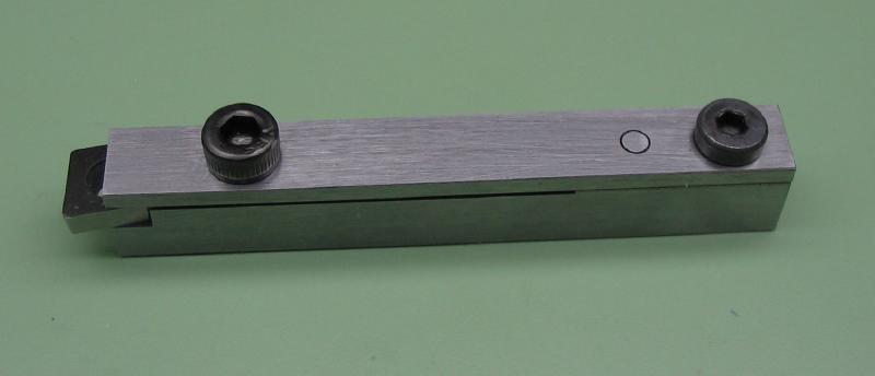
A clamp for holding lathe tool inserts was assembled from 2" lengths of 1/4" square cold roll steel bar and 1/16" x 1/4" oil-hardening tool steel. The strip tool steel was center punched for two screw positions and a steady pin. The rear screw position was drilled 2.5mm and hole transferred to the 1/4" bar. The hole in the bar was tapped M3 and the hole in the strip enlarged to pass a screw.
|
|
|
|
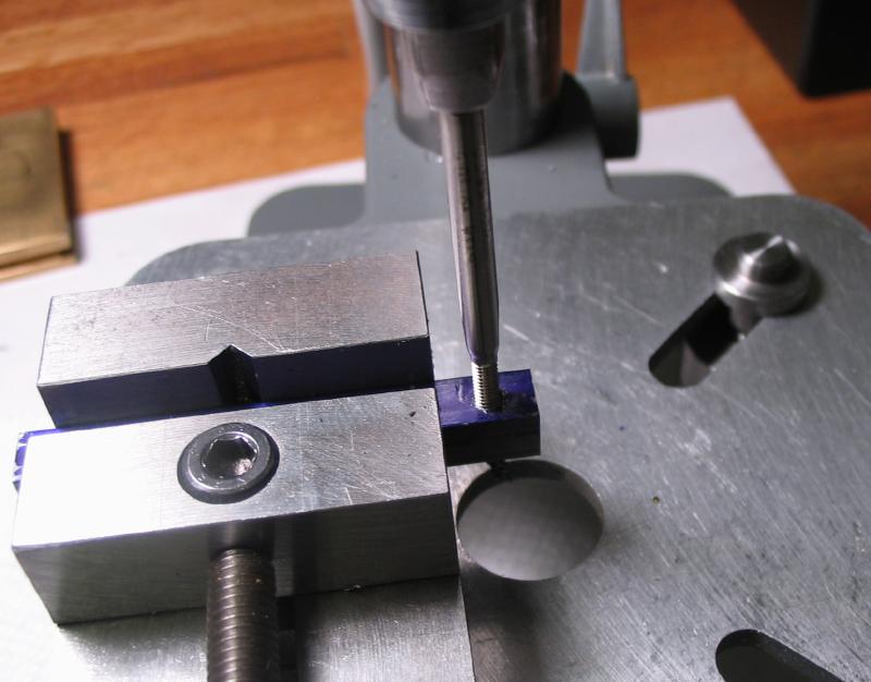
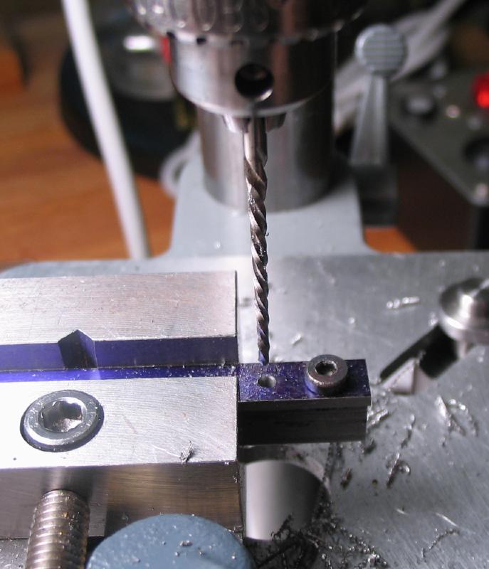
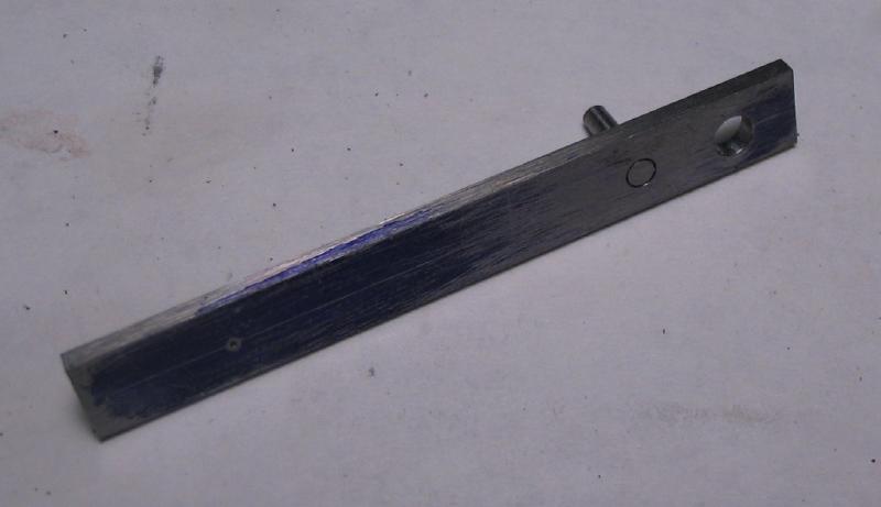
The parts were fit together with a screw and the position for the steady pin drilled 1/16" and then reamed with a #6/0 taper pin reamer. A #6/0 steel pin was driven into the top piece and the reaming continued in the lower piece until a good fit for the pin was found. The pin was then sawed off and smoothed with a file. The second screw position, closer to the opposite end, was then drilled and tapped in the same manner as above. The rear screw would be better if a countersunk type, but not having the desired size on hand, a low-profile socket head type was used. The front screw, which will be used for adjusting the clamp, is a regular socket head screw. Both screws were longer than needed, so they were sawed off and the ends rounded to be below the bottom surface of the clamp.

|
|
|

|
|
|
|
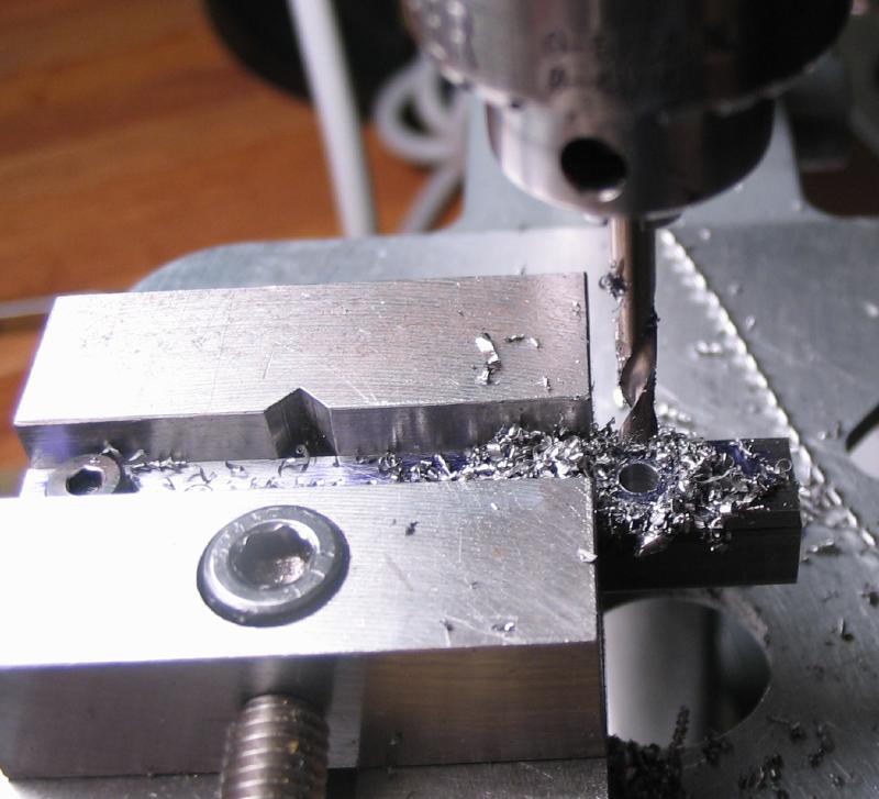
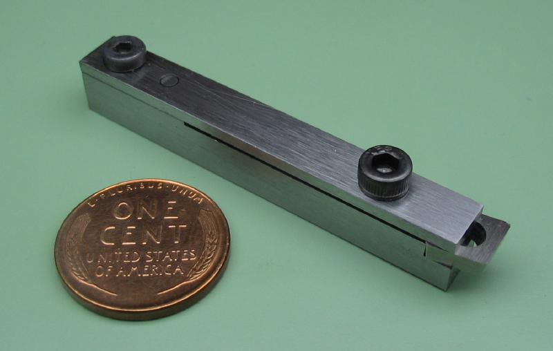
The parts were assembled and mounted in the lathe vice to mill the ends flush. The top piece was removed and lower piece setup for milling. The AR Warner lathe tool inserts I am using are about 3/32" thick, so a step was milled in the end of the bar that is about 2.4mm deep and about 3mm in length. The top face of the bar was milled down about 0.6mm except for the rear area of the screw and steady pin.
|
|
|
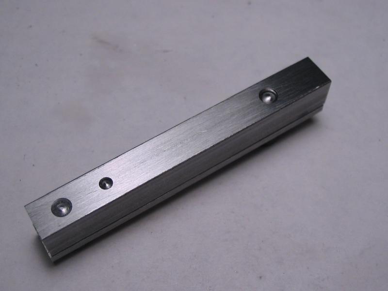
The clamp is complete, and can be used to hold an insert for sharpening purposing.
|
|
