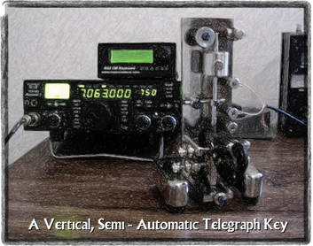
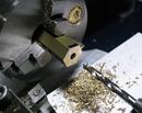
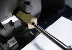
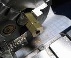
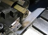
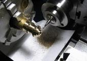
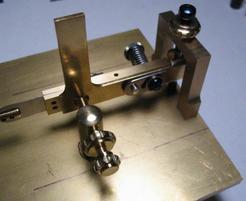
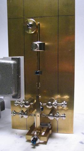
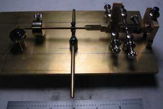
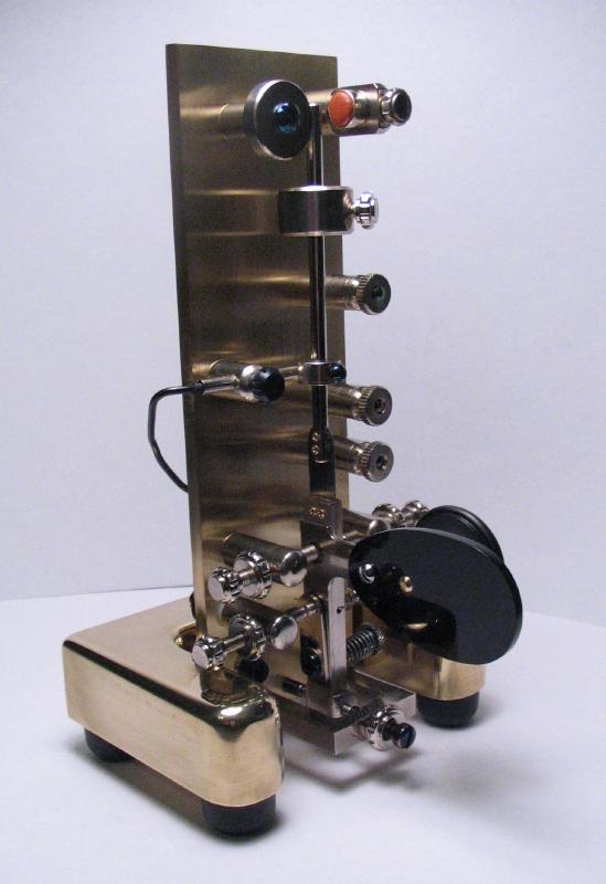
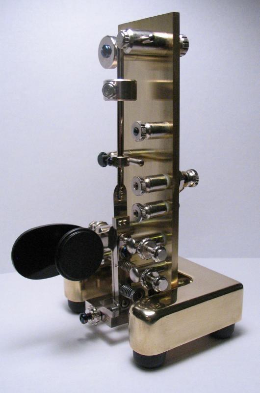
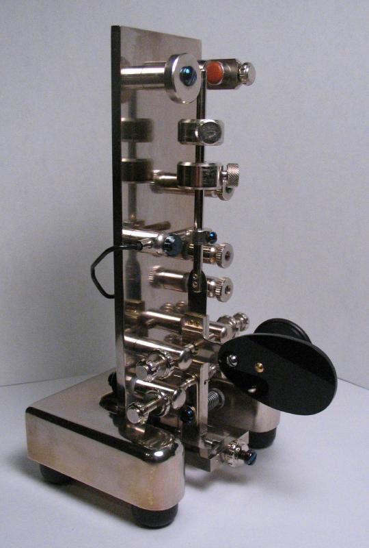
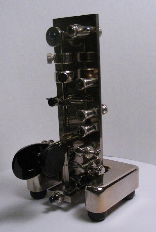
I refer to William Smith in a number of instances on this website, since he is the author of many clockmaking and horology-related books and videos that have been an excellent source of ideas and learning for me. Before I had any interest in horology and machining, my hobby interests were primarily with amateur radio. I did not foresee that these hobbies should ever cross paths, but interestingly enough, Mr. Smith was also a ham and made a series of different and unique telegraph keys over his lifetime. He published a book that describes the construction of one of them. It is described as a vertical, high performance, semi-automatic, speed key. In his book, he refers to this key as the Magnavert, but what appears to be the same key on his website is referred to and engraved as the Vertireed. There is also a Magnevert key on his website, but is a different design using opposing magnets in place of a pendulum mainspring. I will be referring to the key made below as the 'Vertireed,' since I think it is the correct name... Mr. Smith passed away this year, 2016, however his collection of books and videos are still available on his website (www.wrsmithclocks.com). I will be following his design for this key more-or-less unchanged, so I will tend to be vague about specific dimensions. I encourage the reader to find his book, especially if intent on making an example of his key. I will document the various steps I used, which often differ from what Mr. Smith describes since we are using different equipment and setups for accomplishing the same end. I thought this may be helpful or interesting for others to see, and I enjoy documenting my work anyway. The key is fundamentally very similar to a Vibroplex semi-automatic key (also known as a "bug"), but is vertically oriented primarily for conserving desk space. Vibroplex still manufactures a range of telegraph keys, including semi-automatic keys. Mr. Smith recommends using some hardware, including screws, nuts, finger knob, spring, etc., that are available from Vibroplex (see their parts page for information).
Most of the materials needed are relatively common and can be found from metal supply shops, such as onlinemetals.com. In addition to the metal stock for this project , most of the screws, fasteners, insulators and other components can be purchased from industrial tool distributors like McMaster-Carr and MSC. There's always a few things that have to be found elsewhere, such as a reed switch, some plastic for the paddle, and I also obtained a few parts directly from Vibroplex and will describe them below.
One addition I had in mind was inspired by another one of Mr. Smith's keys. On his website, the key referred to as the Magnevert includes a separate dot contact (using the existing stop screw) in addition to the magnet & reed switch. There is also a stop piece that can be adjusted to arrest the pendulum. This allows the key to be used as a single lever paddle for use with an electronic keyer. In retrospect, I realized that in the case of the Magnevert, the pendulum and paddle bar are independent and the stop piece is likely used to immobilize the pendulum altogether. In the case of the key made below, the pendulum and paddle bar are connected so it can not be immobilized, but I made a similar style stop piece to dampen the vibration when using the key for electronic keyer use. Unfortunately, the stop piece makes changing weights difficult as well, so this may not be an advisable upgrade.
Paddle-Knob & Pendulum Bars
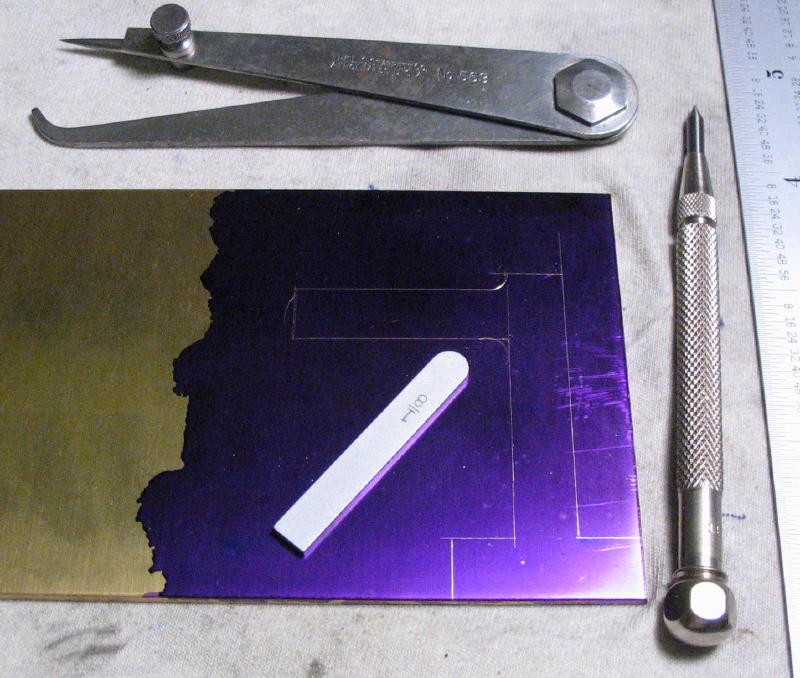
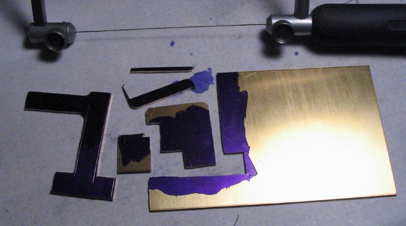
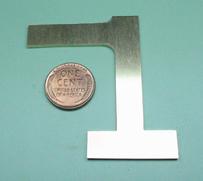
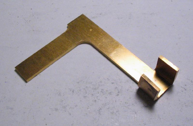
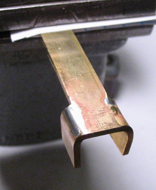
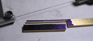
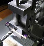
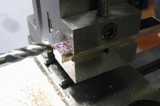
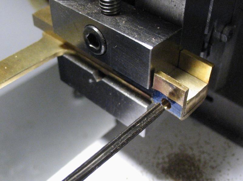
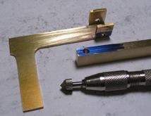
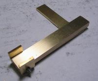
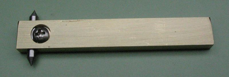
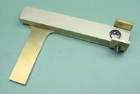
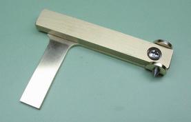
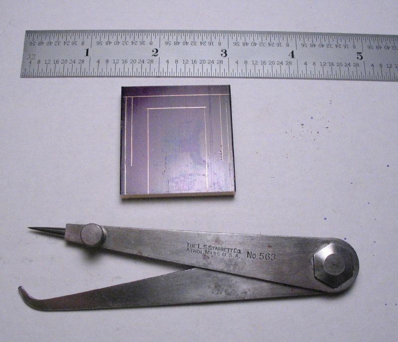
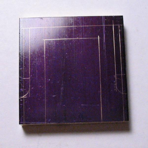
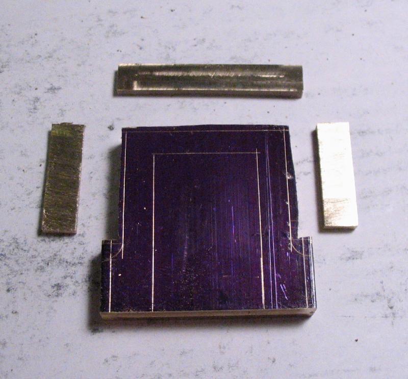
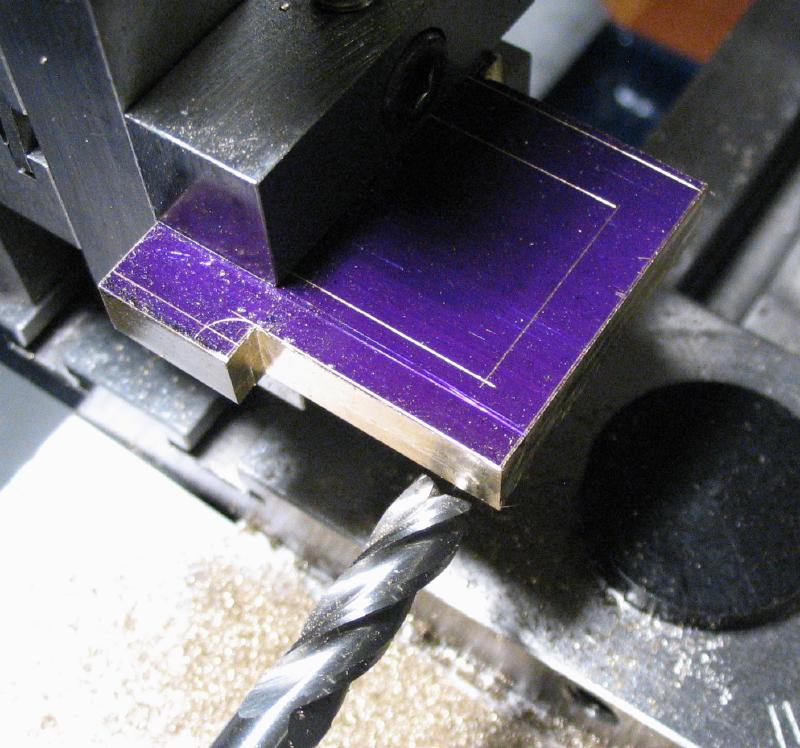
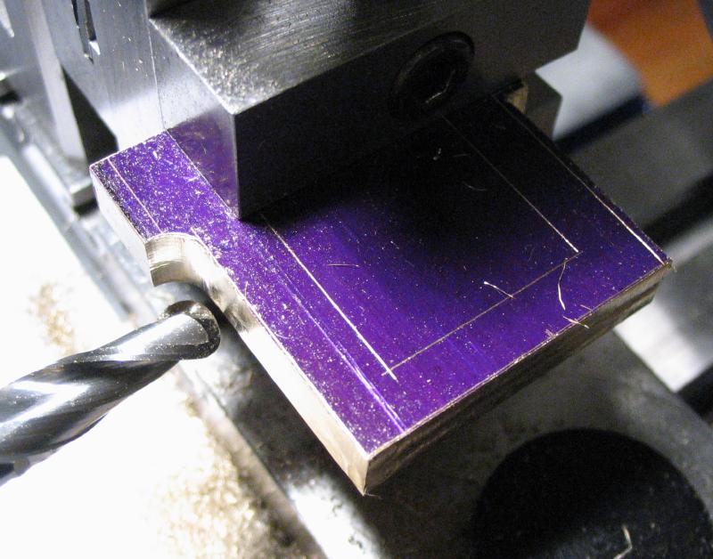
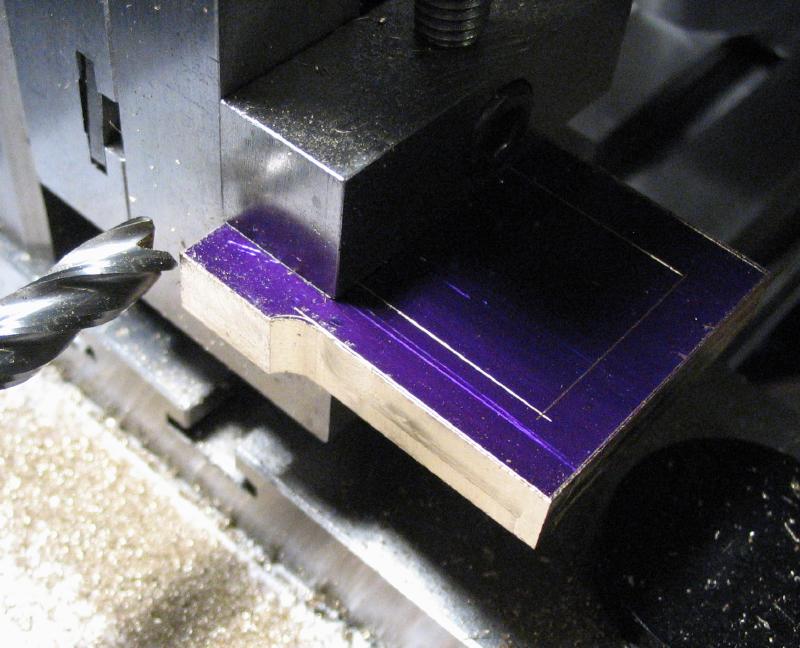
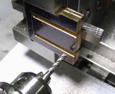
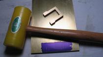
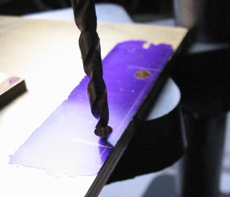
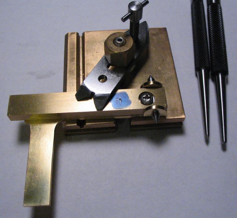
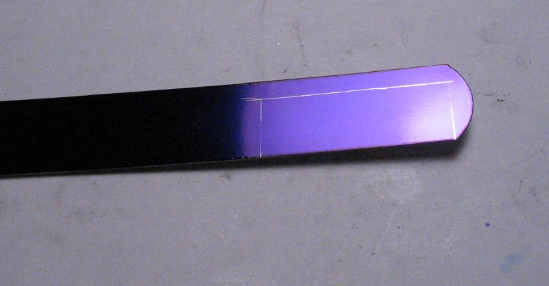
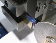
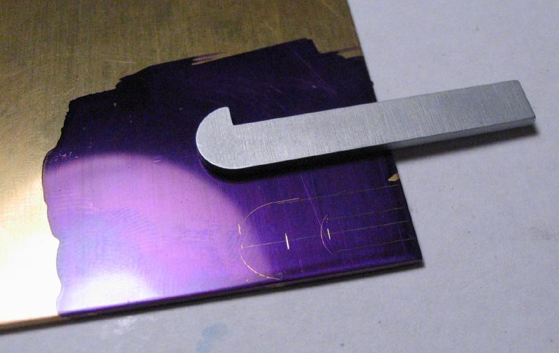
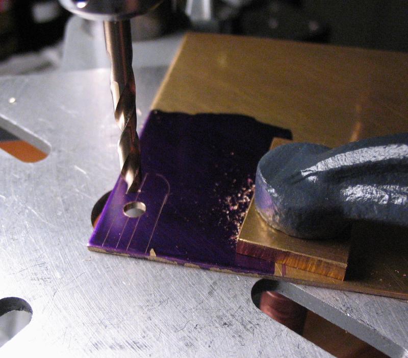
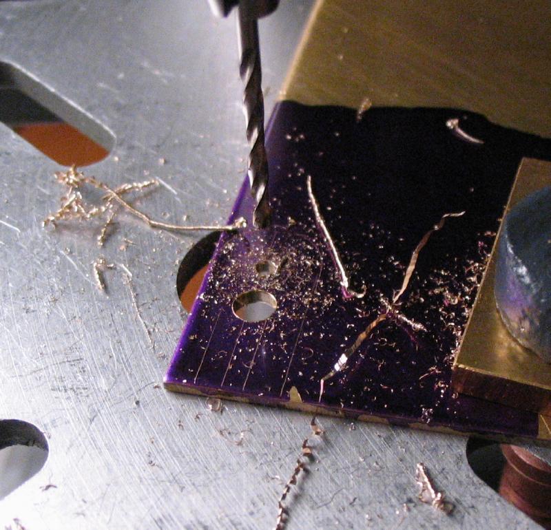
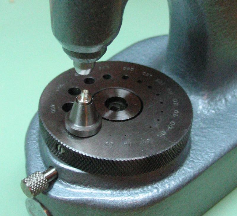
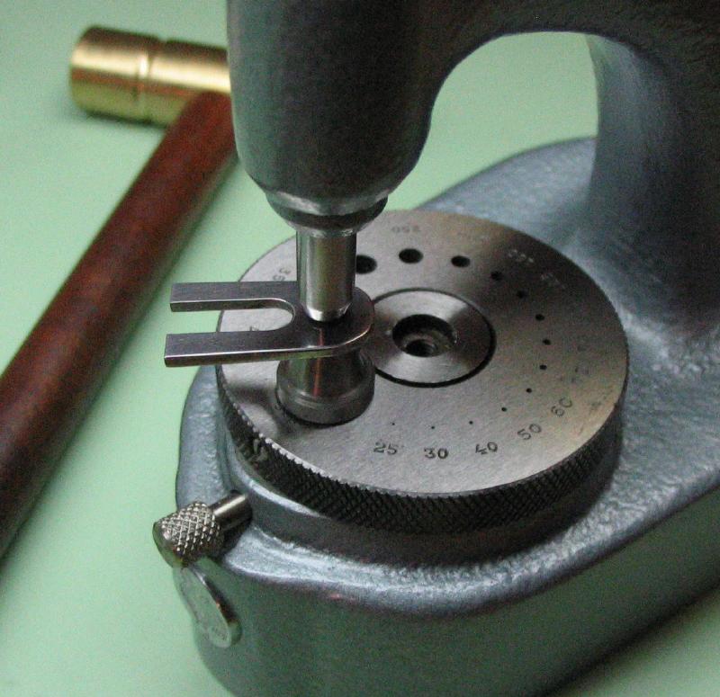
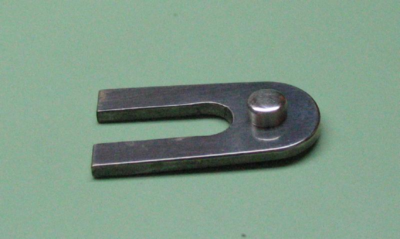
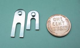
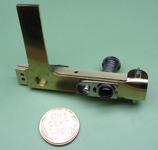
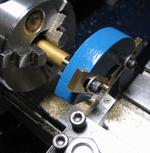
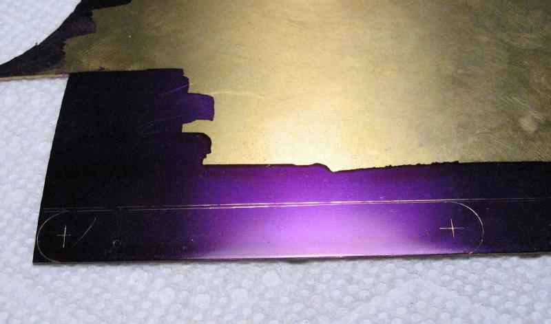
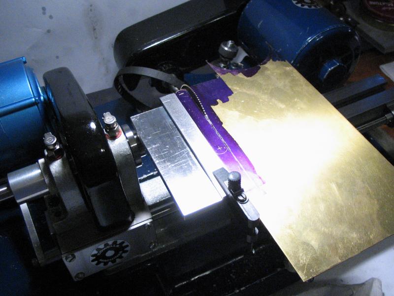
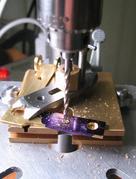
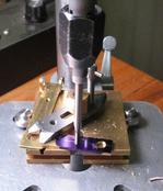
The first part is the paddle-knob bar. The shape is scribed onto brass plate that has been coated in layout blue. Almost all the dimensions were scribed using a jenny leg caliper and the edges of the plate for reference. I am using type 353 brass, which is a leaded and free machining brass. It is similar to 360 brass, but available in some thinner dimensions than is normally available with 360. I had to make a second paddle bar; the first image is of the first attempt, and the other photos of the process are of the second attempt. I will show what went wrong with the first one later on.
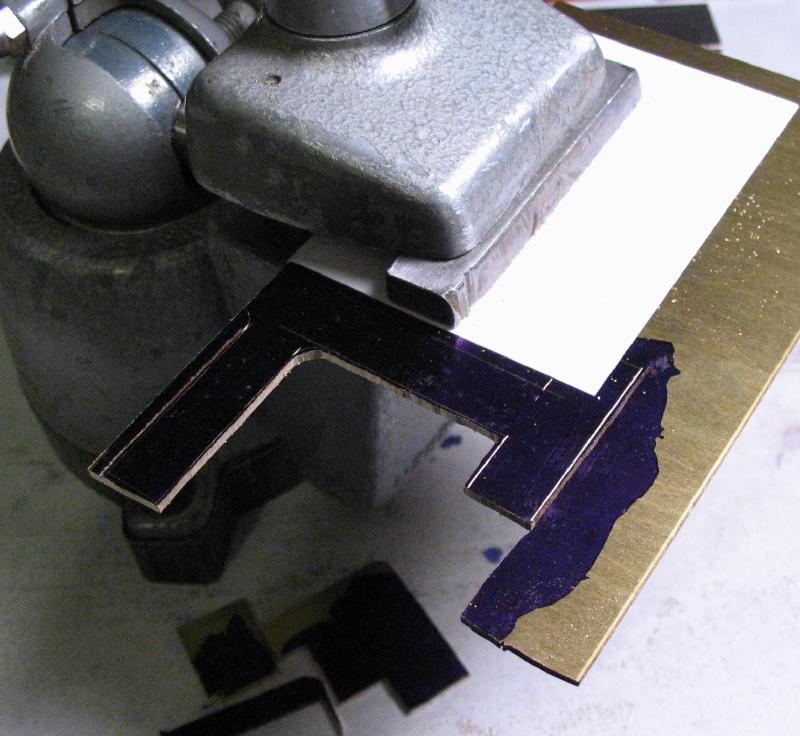
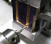
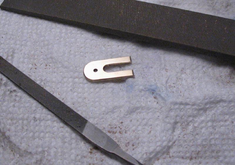
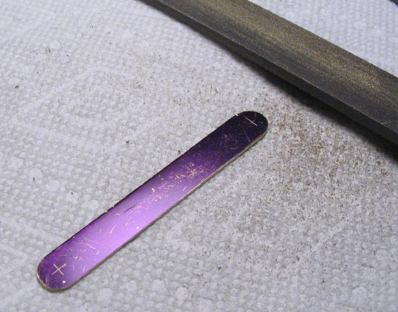
The shape was cut out with a jewelers piercing saw and the edges filed to final shape with flat hand files and needle files when needed, especially in the radiused corners.
The shape was cut out with a jewelers piercing saw and the edges filed to final shape with flat hand files and needle files when needed, especially in the radiused corners.
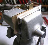
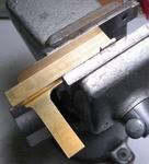
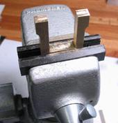
It helps to hold the work in the vise while filing long edges. I used index cards cut-to-size to help protect the brass from the vise jaws.
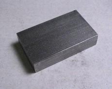
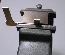
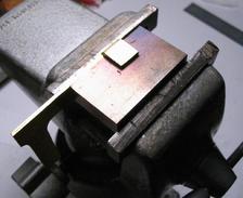
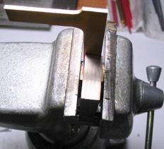
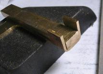
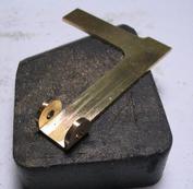
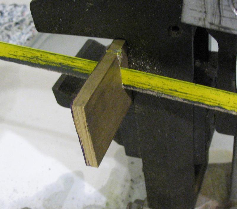
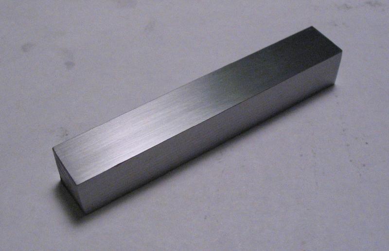
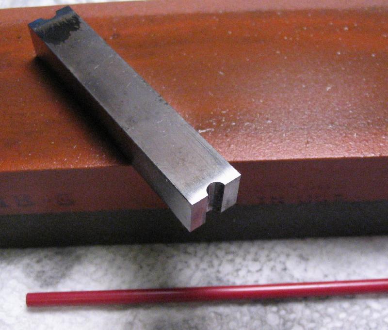
A length of cold-roll steel bar was sawed off and the opposing edges milled flat and parallel. The steel bar is the same thickness as the center beam of the paddle-knob bar and the width of the steel is simply enough to clear the width of the ear tabs and, of course, be able to fit between the vise jaws. The paddle-knob bar is mated with the steel plate and clamped in a vise. One of the ears is heated to a red color and the ear bent over using the steel plate as a former and a piece of wood to push on the ear tab. The work is flipped over and the process repeated for the other ear.
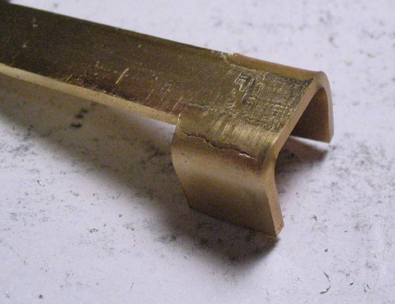
The bends resulted in some cracking at the corners. Mr. Smith suggests heating the brass red hot to prevent cracking, but I had some trouble getting the brass up to a red hot temperature since the vise seemed to act as an excellent heat sink. I used a propane plumbers type of torch, but that may not provide enough heat. I don't know if it will help, but I painted the cracks with flux and then filled with silver solder. The surplus solder was then filed smooth. The cracks were not very deep, and the solder may prevent catastrophic failure in the future and at least the surface will look better when finished.
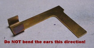
I mentioned this was the second attempt... the first try got as far as bending the ears over, but I neglected to double check the direction or didn't think about it at all, and bent the ears the wrong way! Instead of attempting to correct this one, I started from the beginning.
After soldering and filing smooth, the ears were squared up a little better by clamping them sandwiched with the steel former in between.
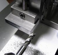
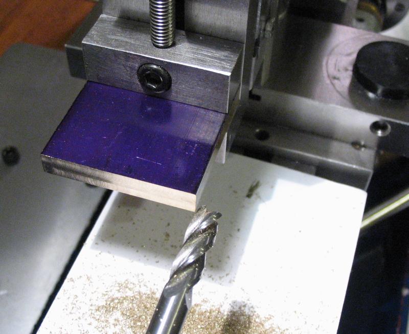
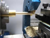
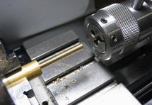
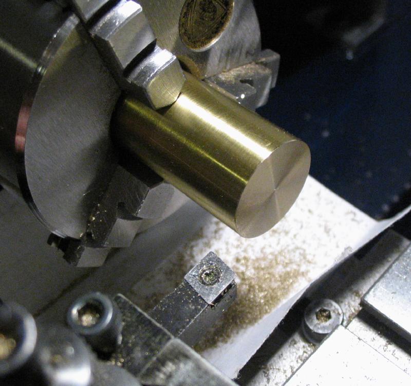
The second part is the pendulum bar, which mates with the paddle-knob bar. It is made from brass bar stock (type 360 brass), and I used a slightly oversized width, so a strip needed to be sawed out. The edges were then squared up on the lathe, using the vertical slide and machine vise with an endmill.
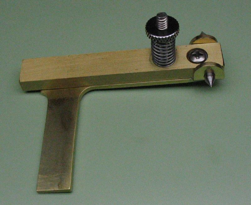
The pendulum bar fits between the ears of the paddle-knob bar. A feeler gauge is inserted between one of the ears and the pendulum bar. The ears are then clamped closed in the vise again to remove all clearance. The feeler gauge is removed, and the desired side-shake should remain. The ends of both the bars can be filed even while together.
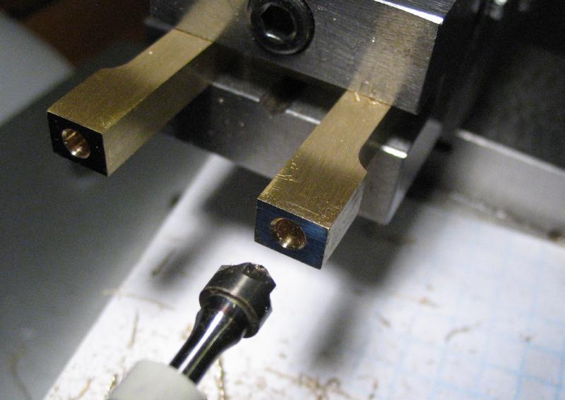
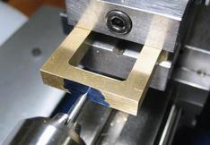
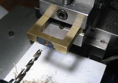
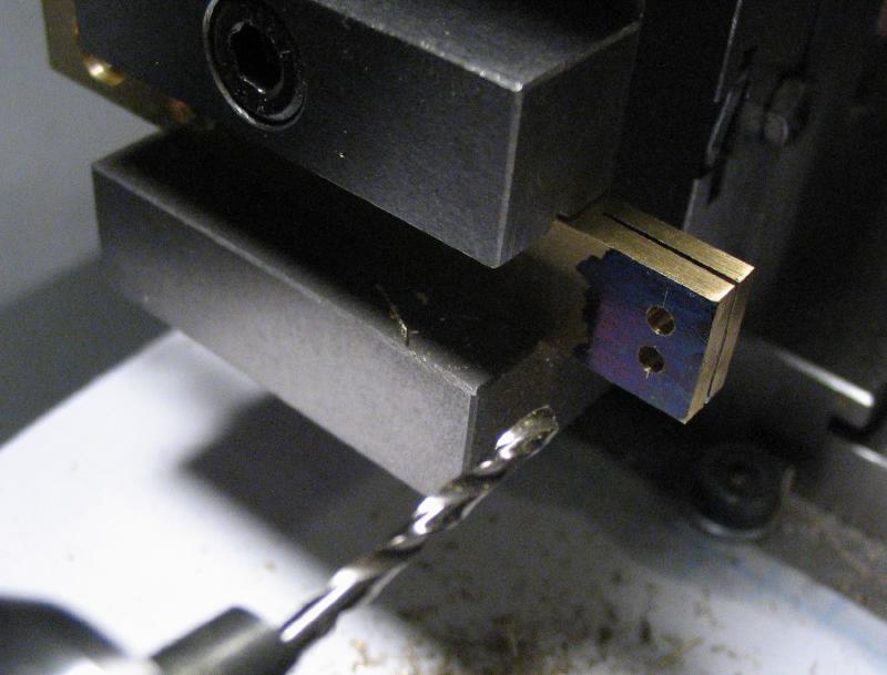
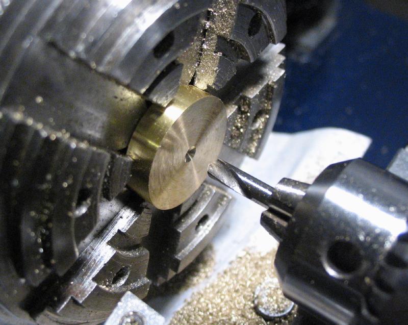
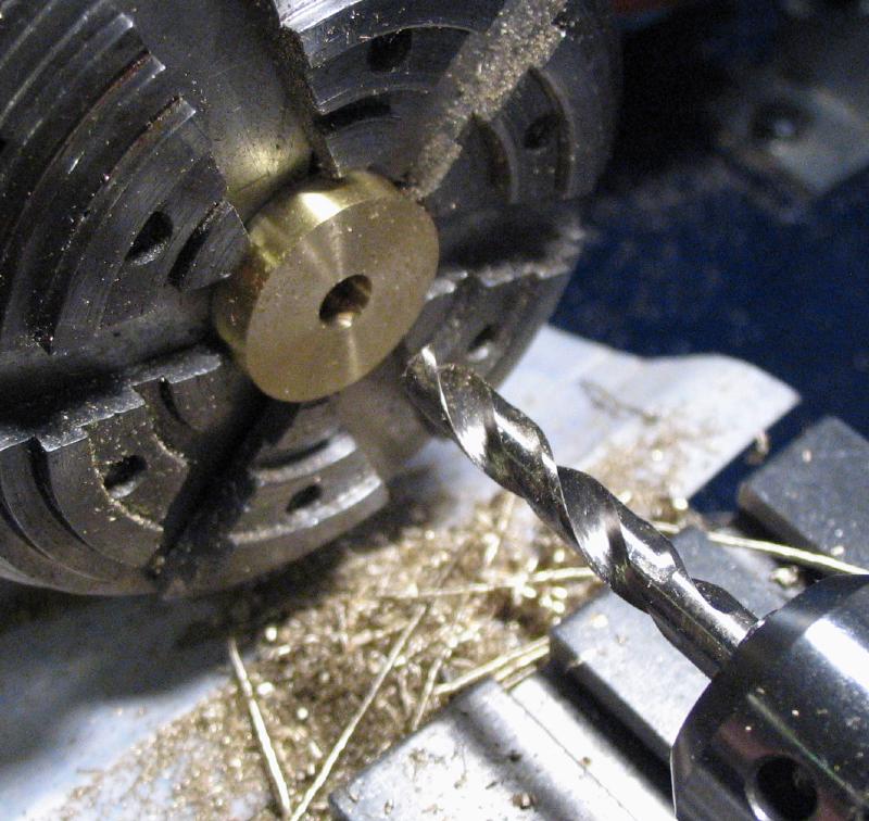
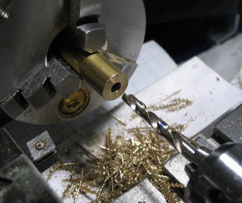
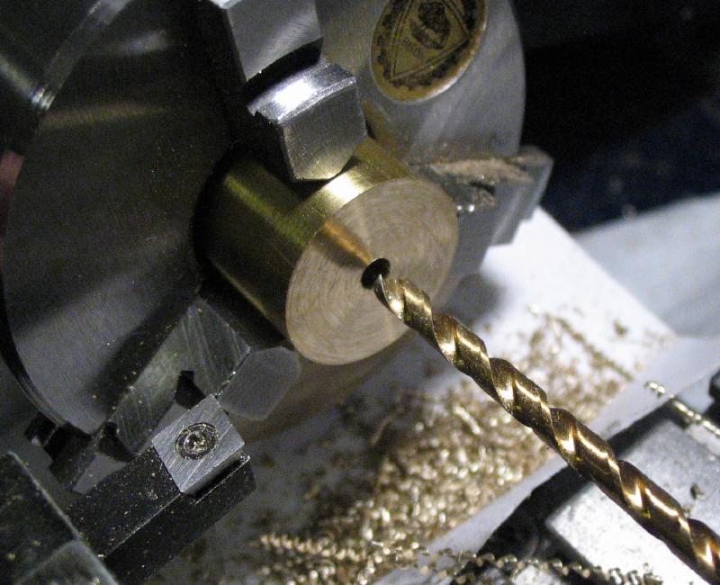
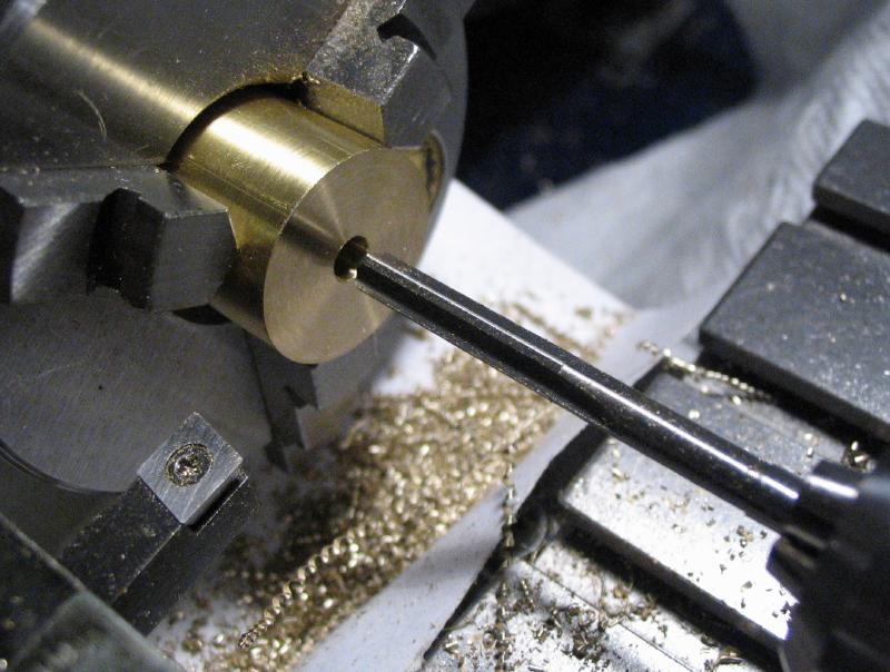
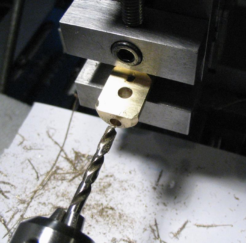
The paddle-knob bar and pendulum bar are mounted together in the machine vise. The center was found of the pendulum bar, and then the center of the ear was found. These two centers together give the location for the arbor. It was spot drilled, and then drilled undersized for reaming to match the arbor made below.
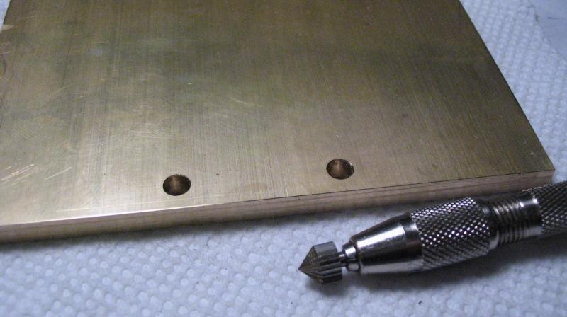
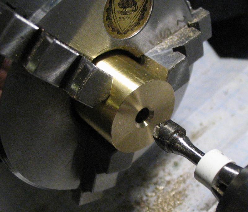
The holes were lightly countersunk with a jewelers burr.
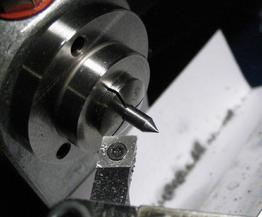
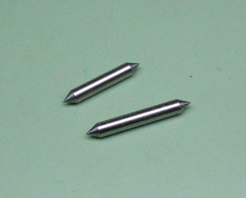
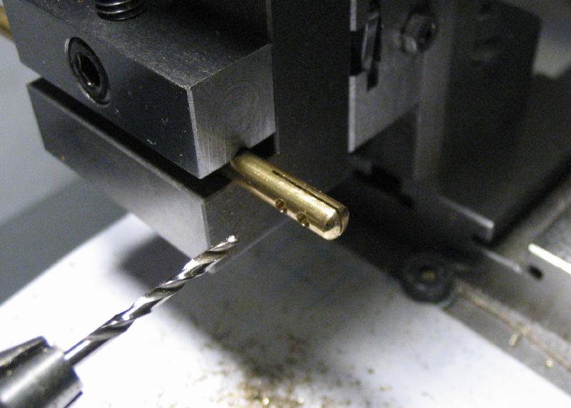
The arbor was made from a length of oil hardening drill rod that was turned on both ends with a taper that matches my countersink drills (60 degrees). It was left in the annealed condition. The arbor is a slip fit in the pendulum & paddle-knob bar assembly, and could be tested for fit at this point. I made the arbor to the specifications in Mr. Smith's book, however, the arbor appears to be much longer in his photos. I decided to make a second arbor with a little extra length, however, the final dimensions will be ascertained later.
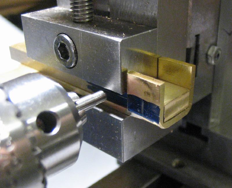
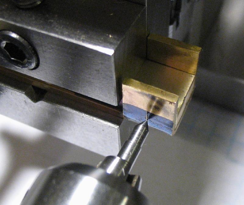
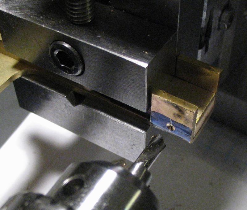
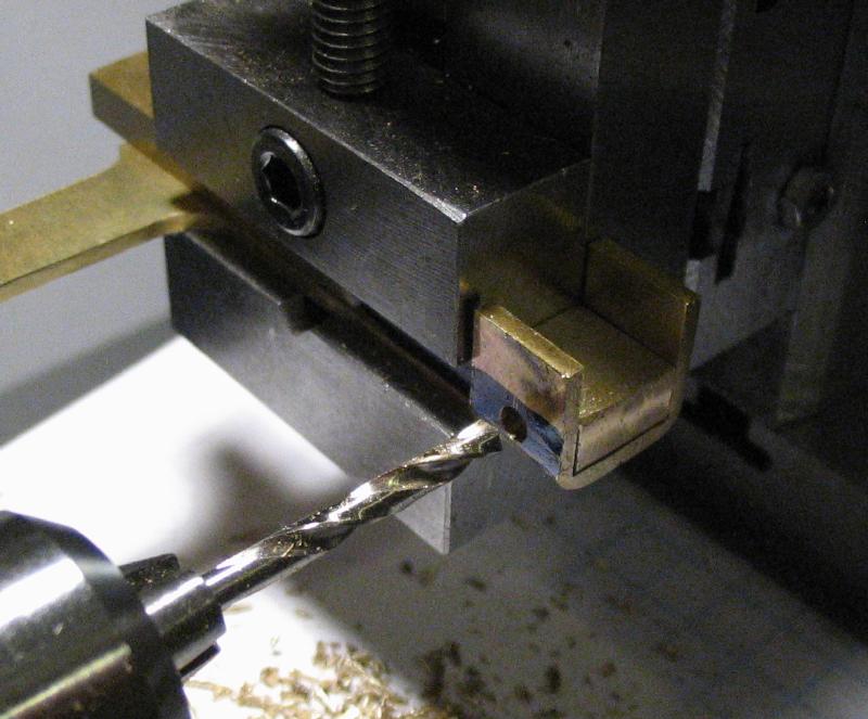
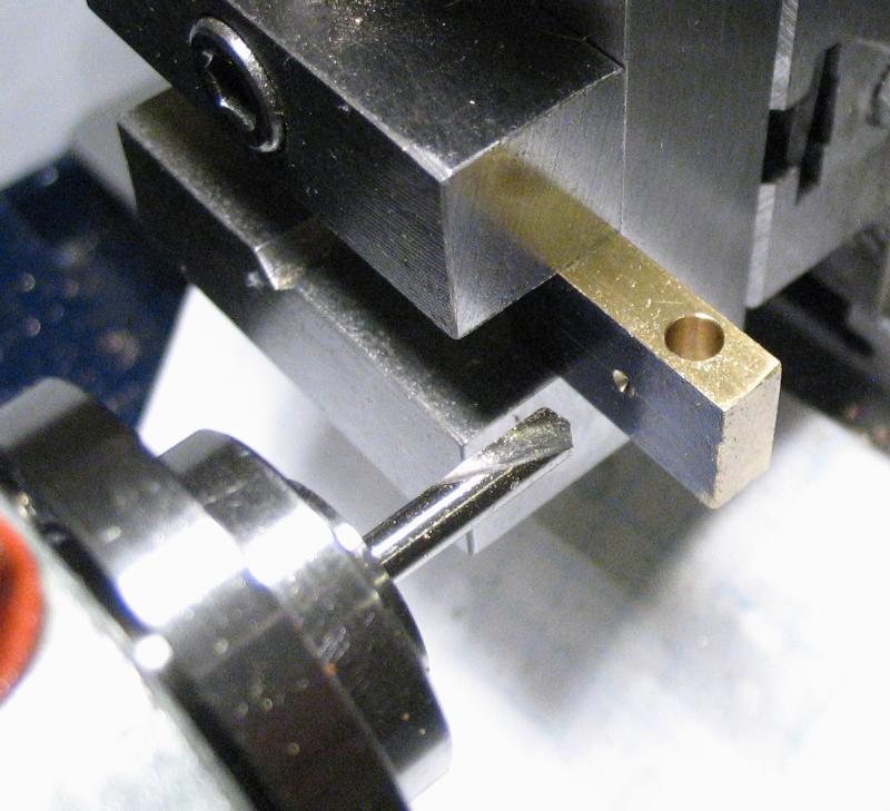
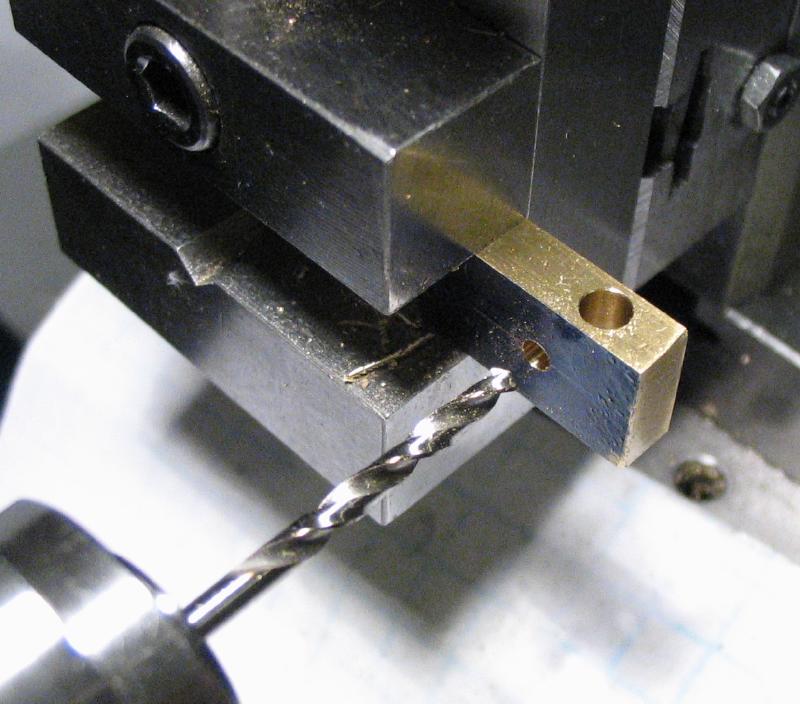
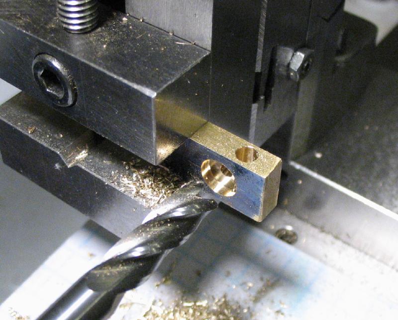
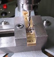
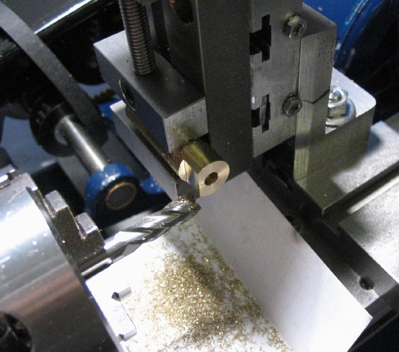
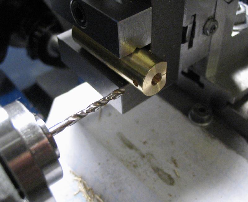
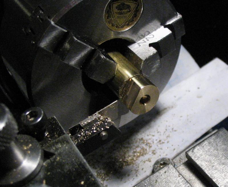
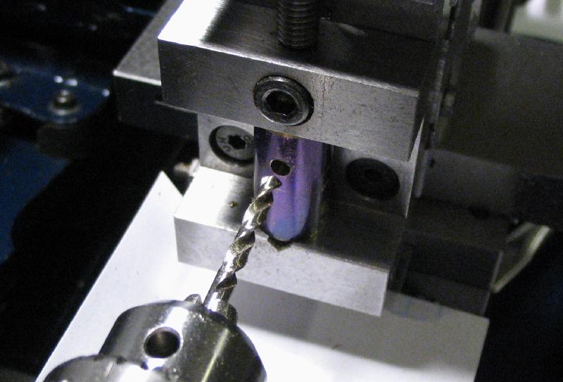
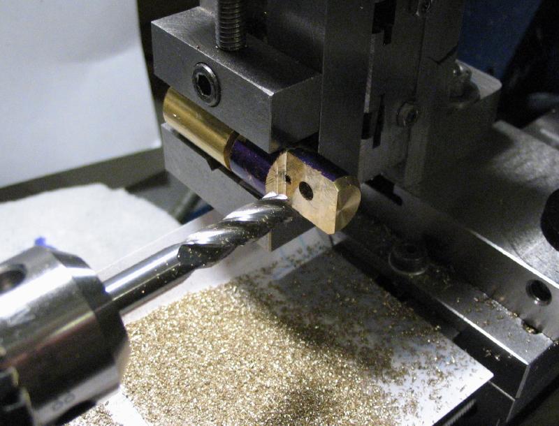
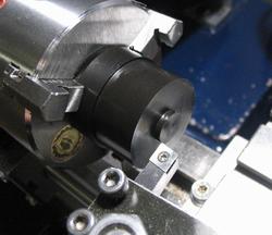
To secure the arbor in place, a screw is needed. The position for the screw must be far enough away from the arbor that the threads do not foul the arbor, but close enough for the countersink of the screw head to make contact with the arbor and lock it in place. This offsest distance can be calculated from half the screw diameter plus the desired clearance added. This is then found on the lathe using a plug gauge mounted in a collet in the headstock and aligned to just touch the arbor while the pendulum bar is mounted in the machine vise. Once the position is found, the plug gauge was exchanged for a small point and brought onto the center line of the bar. The position is spot drilled and then drilled through for tapping. The hole was counterbored with an endmill to a depth about half way through the arbor hole.
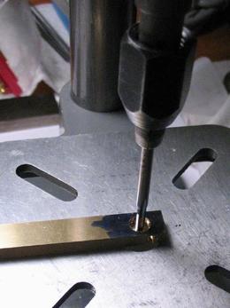
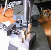
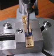
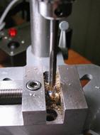
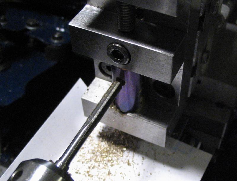
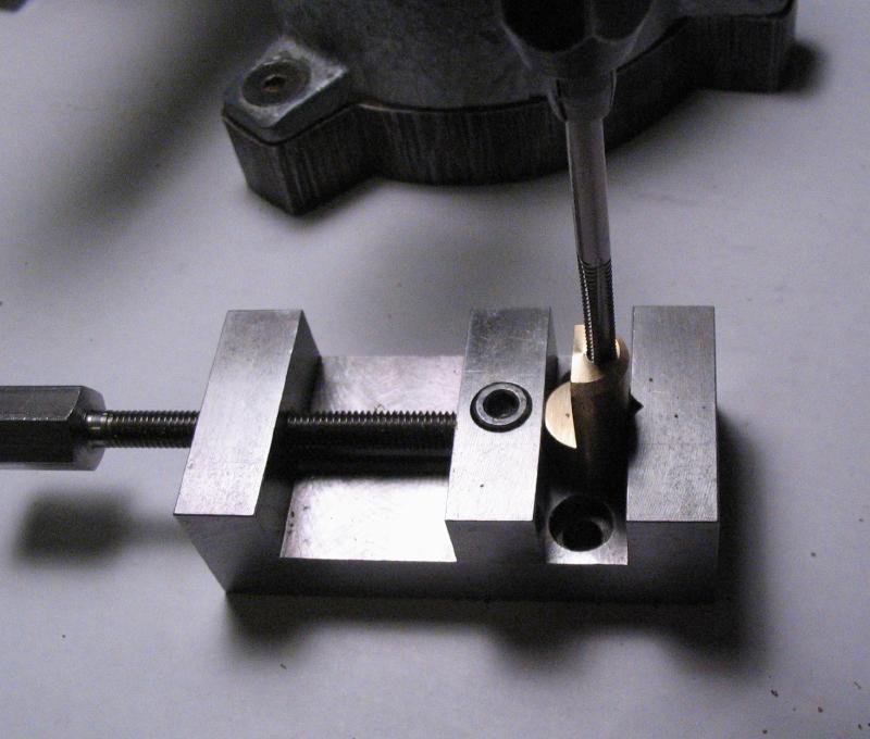
The hole could then be tapped, this was done on the drill press with a tap wrench, but the drill press can be used to help keep things upright. A stock, stainless steel countersunk screw was used with matching threads and long enough to just be flush with the other side of the pendulum bar. By 'stock,' I mean that the screws can be purchased from your favorite hardware supplier.
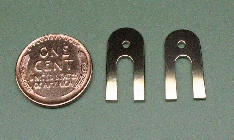
The ear tabs on the paddle-knob bar can finally be shortened and rounded over to their final shape. Flat hand files and needle files were used here. It was a slow process as the shape is formed gradually with files. Both ears were filed at the same time to keep them even. The work was given a quick polish while I as at it. Mr. Smith comments that this completes the most difficult part of the key, however, we shall see about that!
The Bridge
The bridge was started from leaded brass bar stock (type 360) that was purchased in the correct thickness and slightly oversized in width. An oversized length was sawed off, and one of the sawed edges milled square. This edge and the extruded sides of the stock were used as references to scribe out the basic dimensions with a jenny caliper.
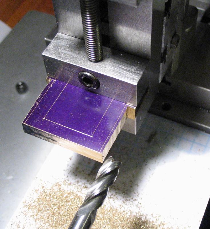
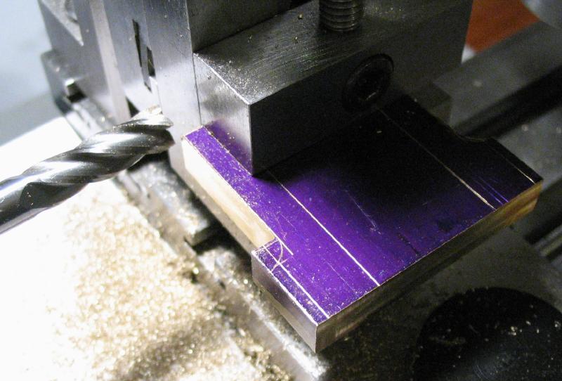
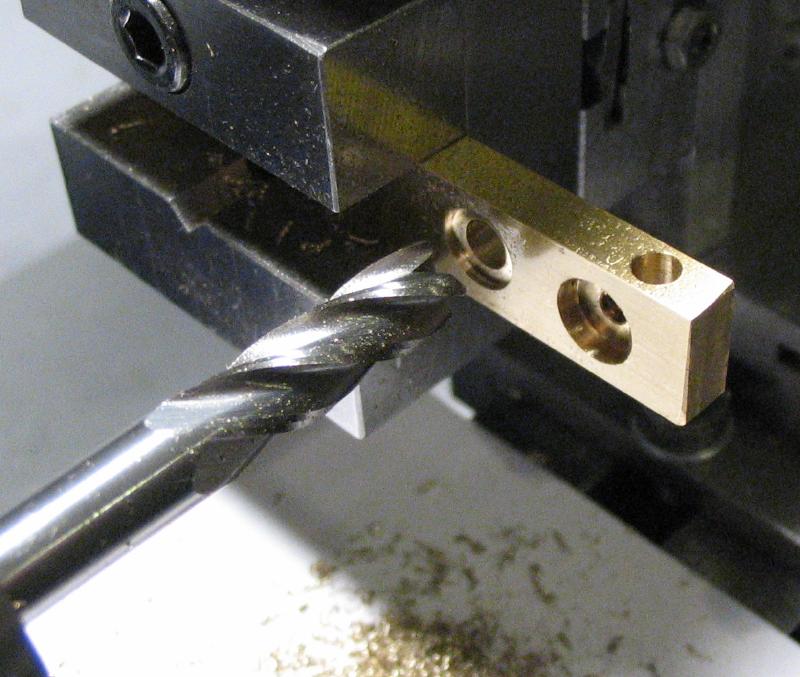
The stock was roughly cut with a jewelers piercing saw, but the edges were brought to shape with endmills on the lathe with the work mounted in the machine vise and positioned with the vertical and cross slides.
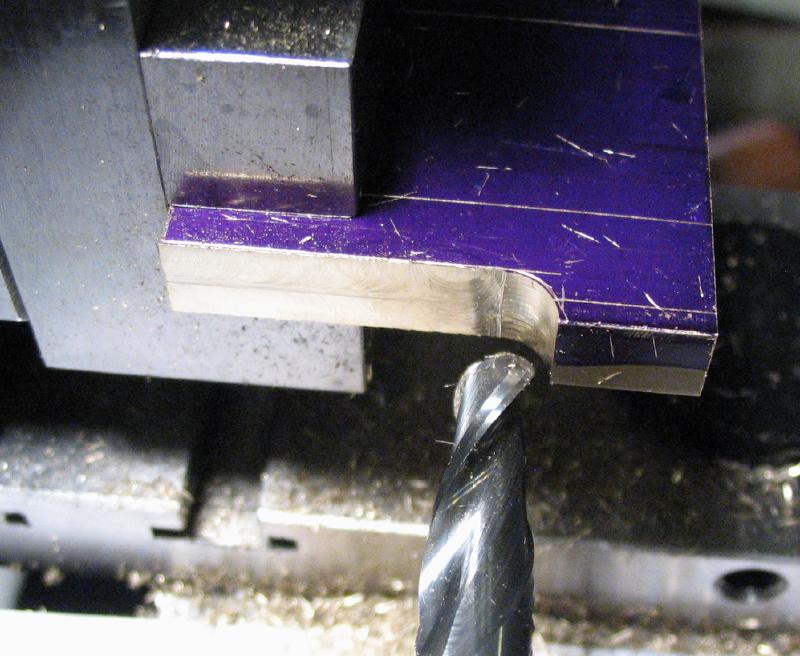
First, the top edge was milled flat, and then one of the sides was roughed out, including the foot. The radius was formed with a large size ball end mill. The opposite edge was then milled in the same manner.
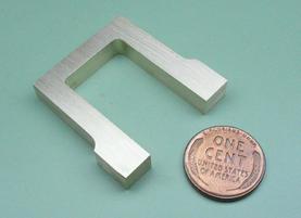
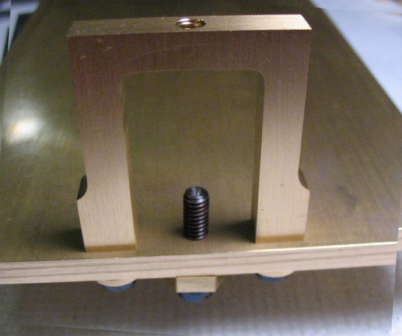
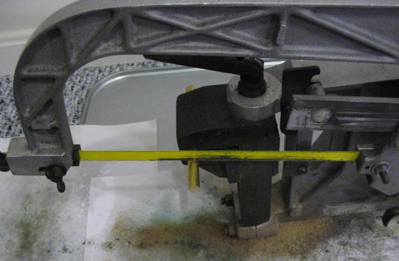
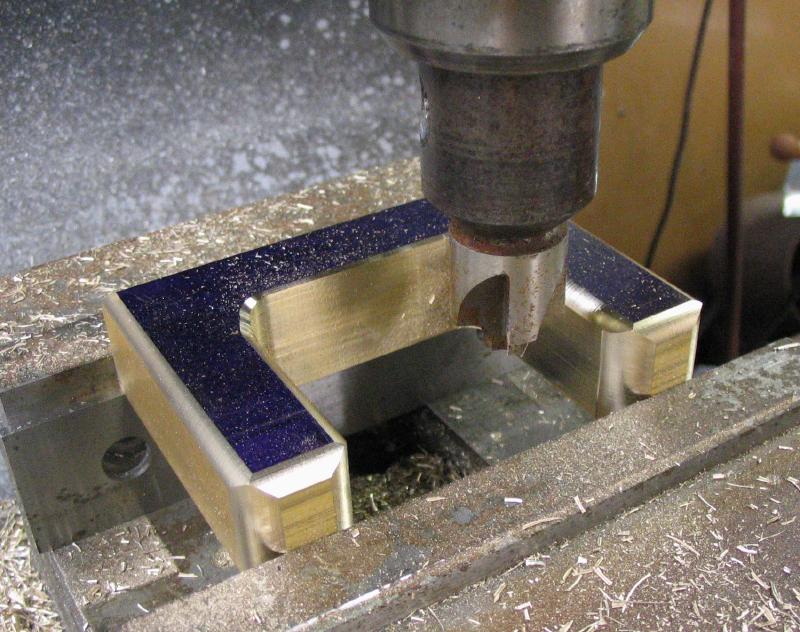
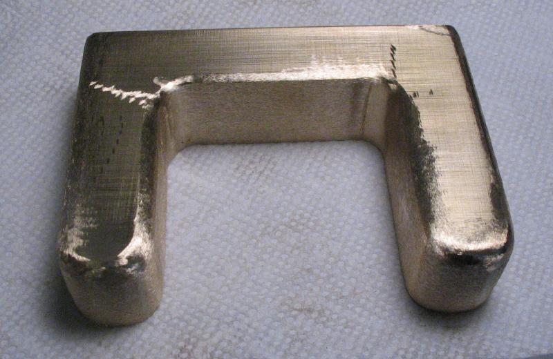
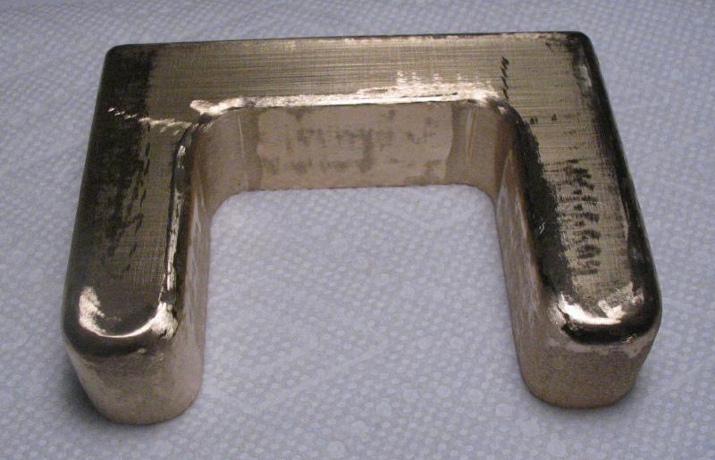
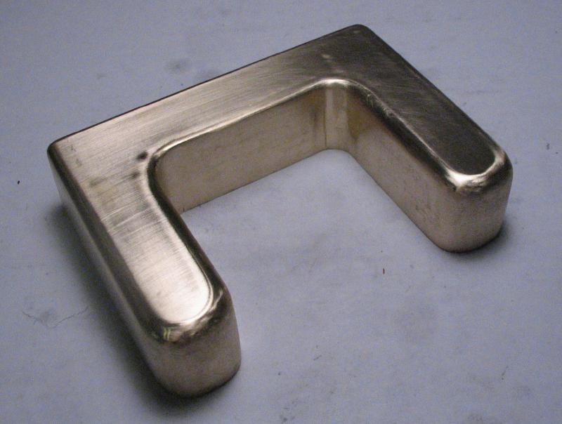
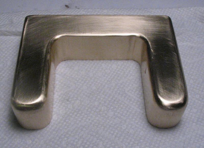
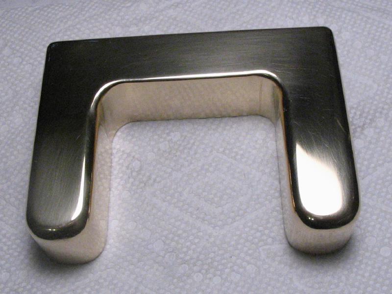
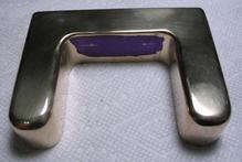
The internal section of the bridge could be sawed out with a piercing saw, but the thick plate adds to the difficulty in keeping the saw upright and straight, which leaves a lot to finish with files. Instead, I decided to mount the bridge back in the machine vise and cut out the internal portion by milling a channel that is all the way through. This process is probably much slower than sawing and filing, but it results in a shape and surface that needs little finishing.
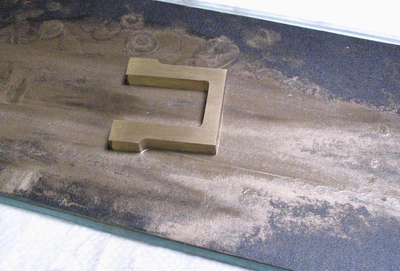
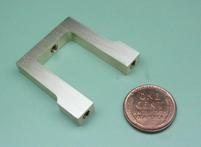
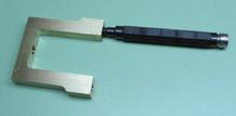
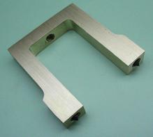
The bridge was held in the vise and the edges were finished with needle files to remove burs and tool marks. The faces were polished with 400 grit emery paper on a glass sheet. Some cutting oil helps keep the emery paper from clogging up. It still needs to be drilled and tapped, but I snapped a photo after cleaning,
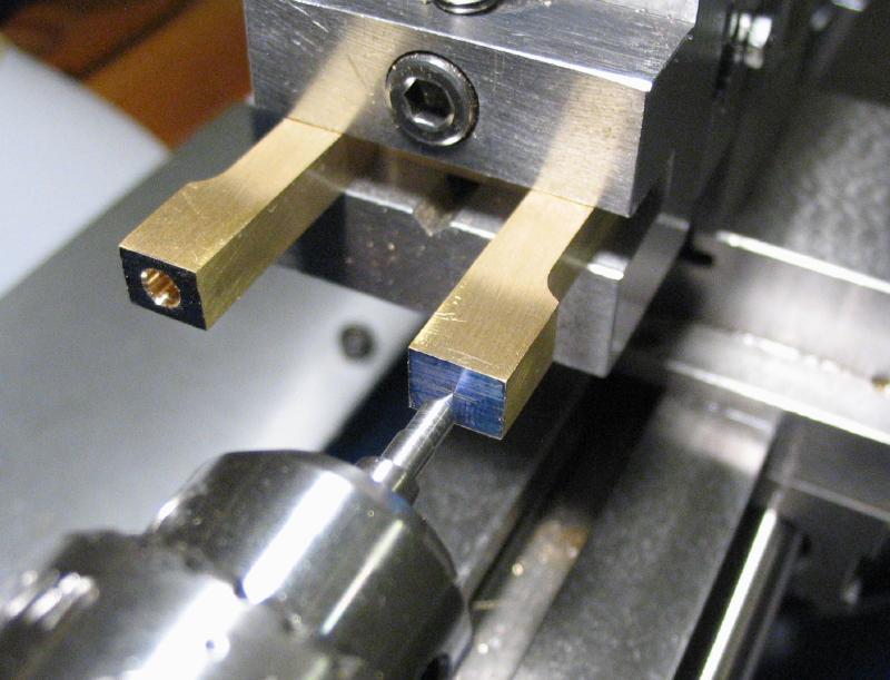
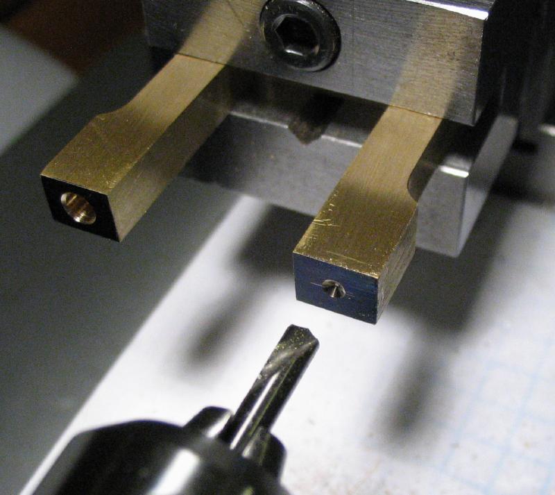
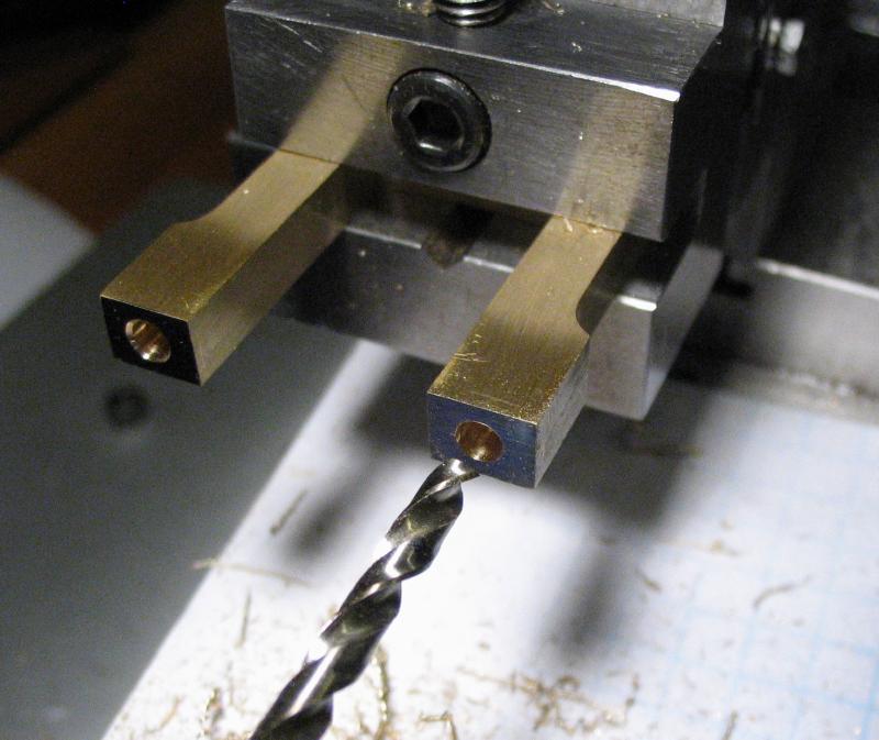
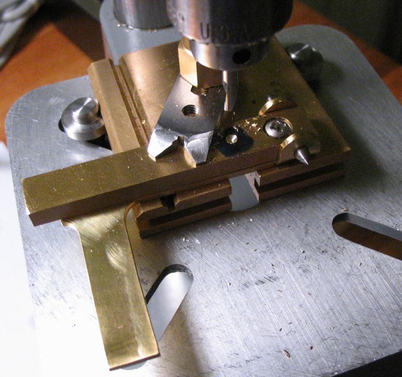
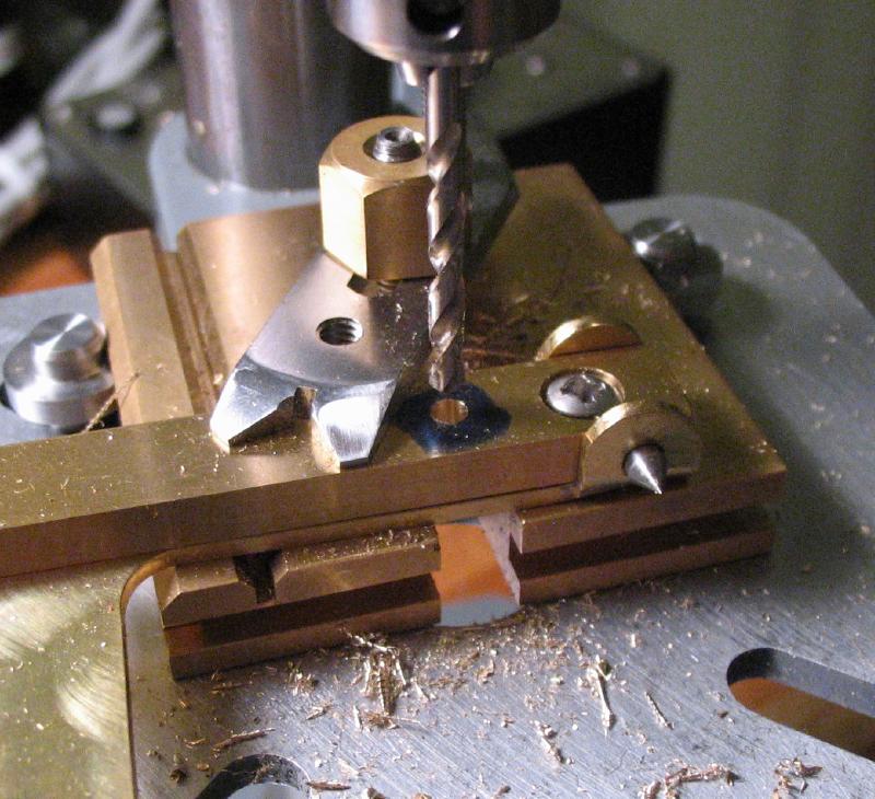
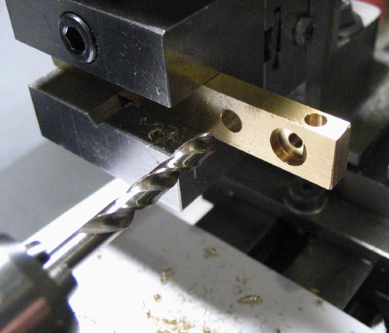
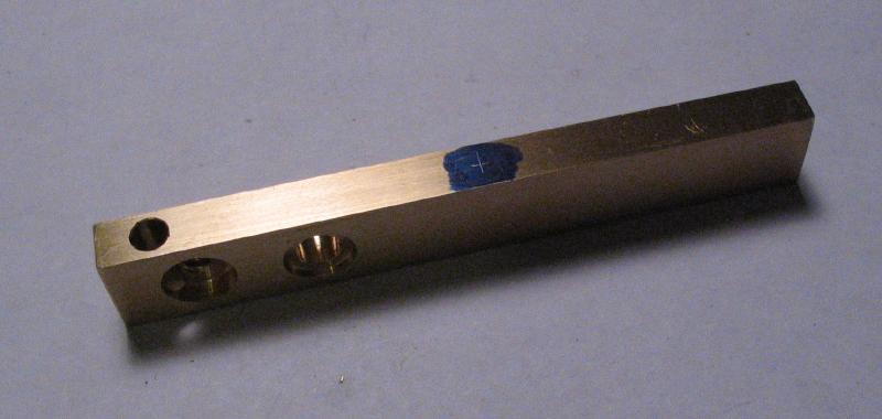
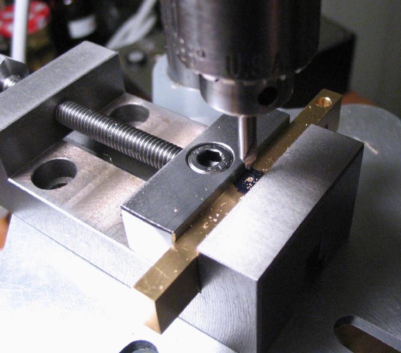
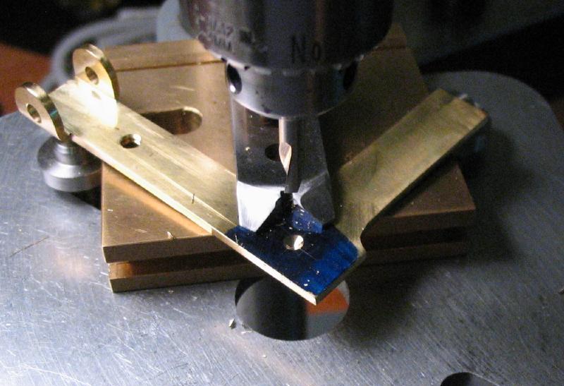
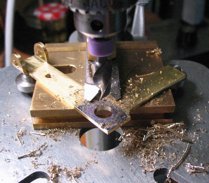
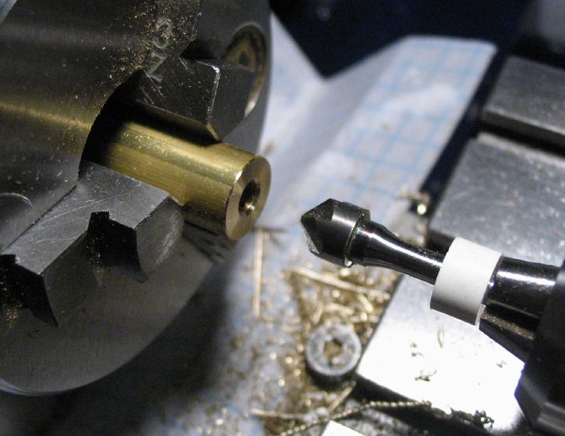
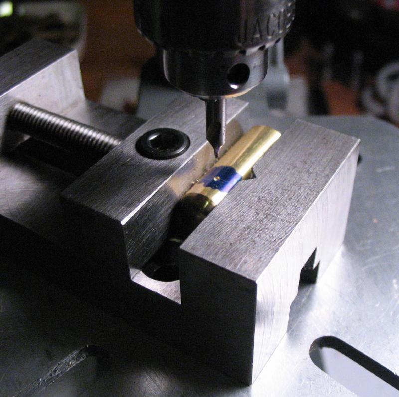
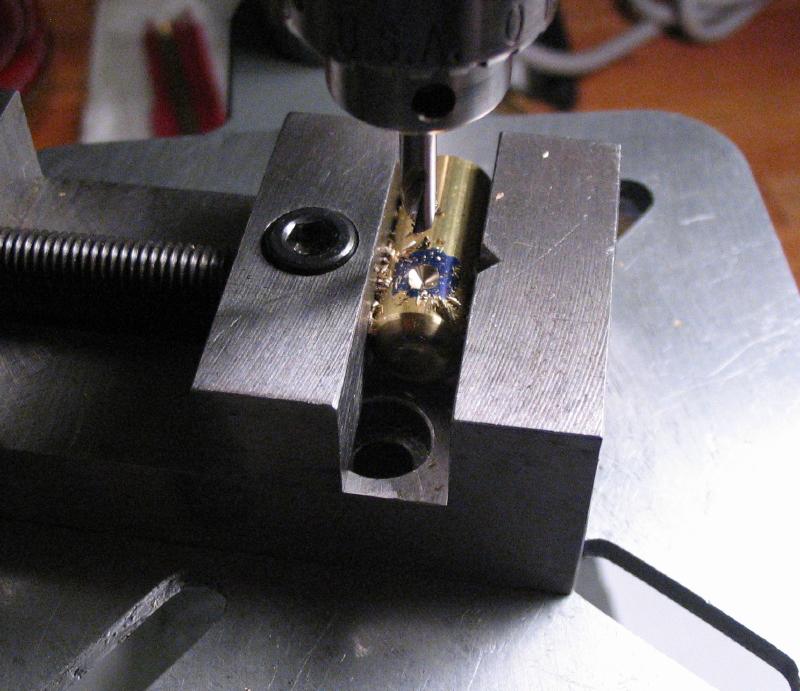
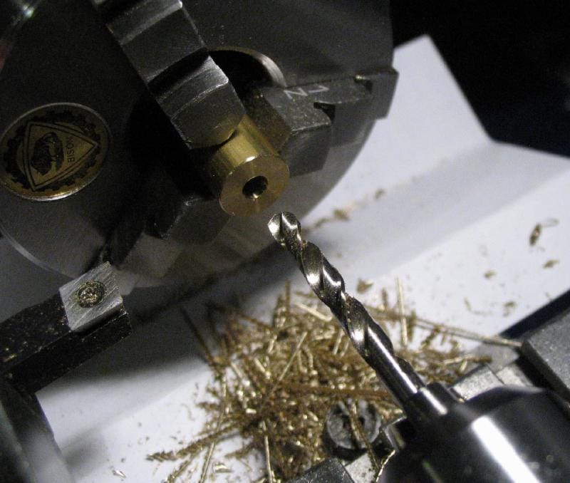
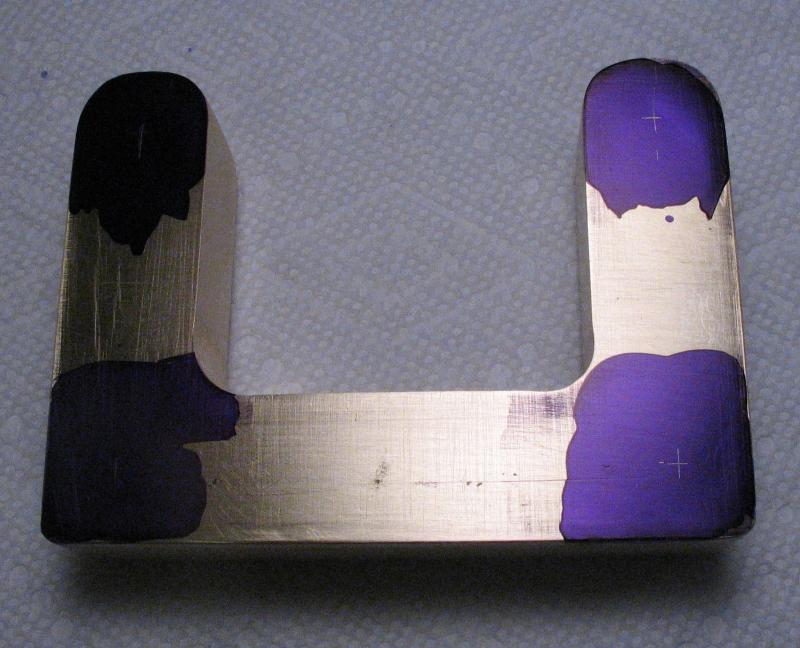
The centers of the bridge feet and the top were found with the jenny leg caliper and scribed. This often looks like a # as a center line is scribed from each edge but the measurement slightly off. The true center is, of course, in the center of the hash. The bridge was mounted back in the machine vise and these centers found with a small point in the drill chuck. The positions were spot drilled, drilled for tapping, and countersunk. The same was done for both feet and then repeated for the top of the bridge.
|
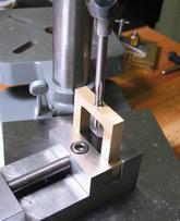
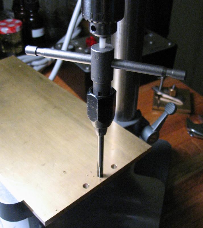
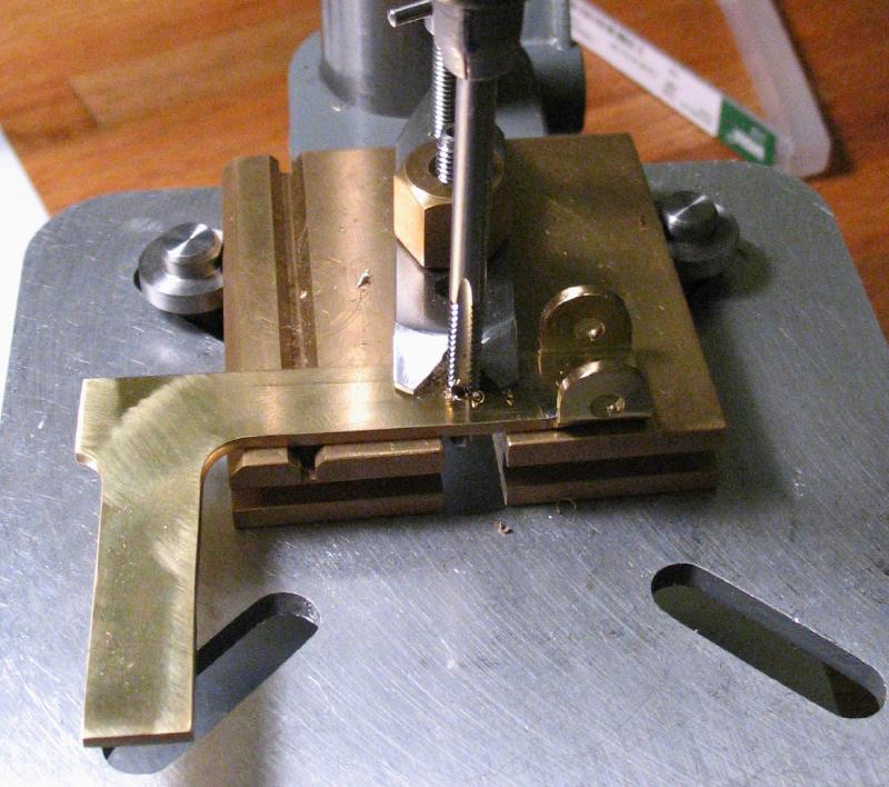
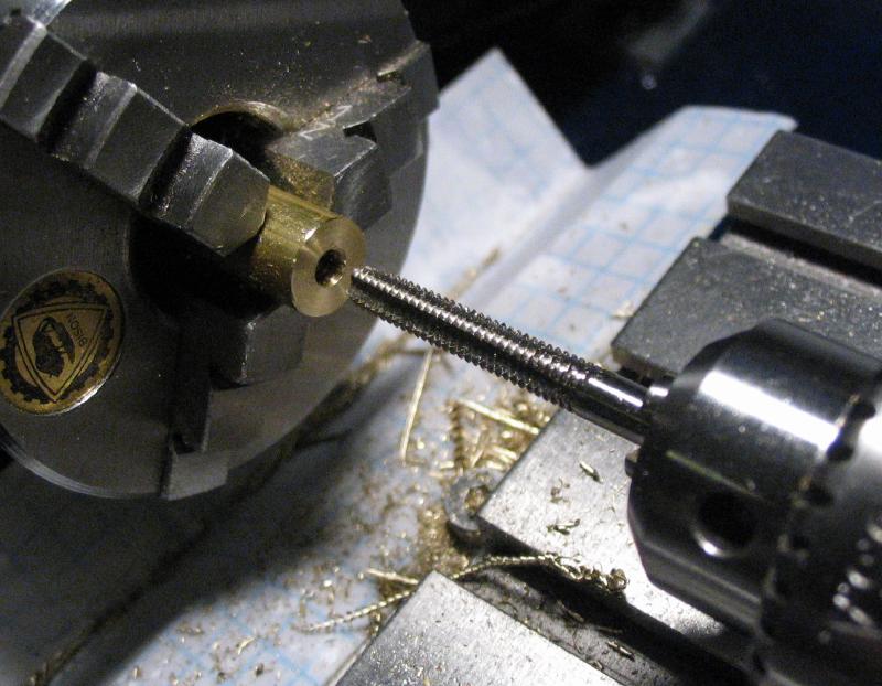
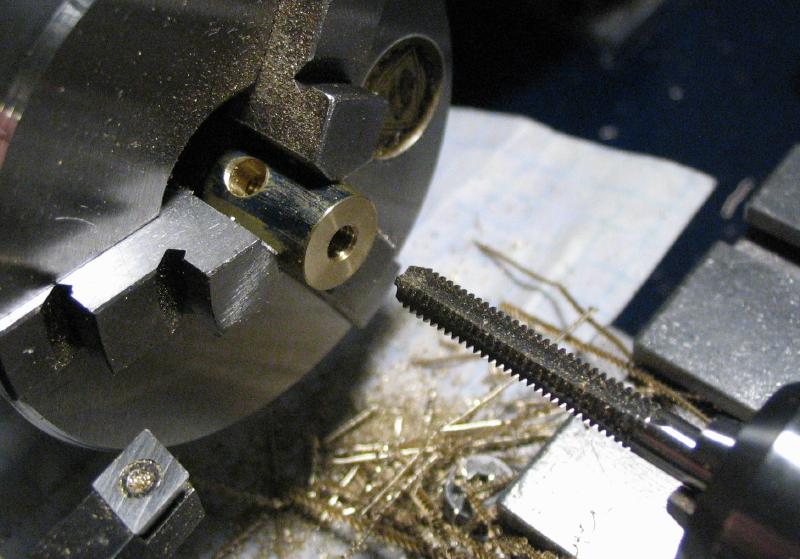
Both feet and the top of the bridge can now be tapped. I use the drill press to help keep the tap and handle upright with a small pin in the chuck. The required height was a little too much, and the drill press table had to be swung out of the way and a steel bench block used in its place. The blind holes of the feet were started with a plug tap and then finished with a bottoming tap to form complete threads to almost full depth. |
When I had the drill chucked and ready to drill the first foot of the bridge, it did not look quite right, and I then discovered an error in Mr. Smith's book. In the front section of his book he provides suggestions for the sizes of tapping drills and clearance drills for the thread sizes used throughout the rest of the book. These drill sizes do not match those suggested by other sources, including Machinery's Handbook. The threads are UNC sizes, which I do not have much prior experience with. The recommended tapping and clearance drills are number-size, which I find to be an unintuitive system to work in. The lesson here is to always double check, and Mr. Smith points out that the proper tapping drill is the diameter that will fit through a threaded hole (e.g. a nut), and likewise, the proper clearance drill is one that will produce a hole that passes the threads (e.g. a screw). Of course, you need to have a screw or nut to use as an example.
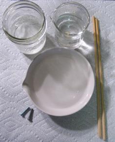
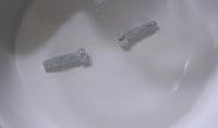
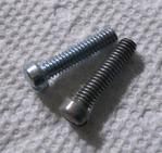
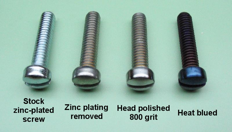
The screws for the bridge and many of the remaining screws needed for the key are stock screws. I purchased zinc-plated steel screws, but the zinc plating can be easily removed. Mr. Smith recommends a 6 to 1 solution of water to muriatic acid to dissolve the plating. Muriatic acid is a 10% (or there about) hydrochloric acid solution that is sold in home supply stores. My setup is below, and includes a shallow porcelain dish for the acid bath, a jar containing a tablespoon or so of baking soda in water (there's some that did not dissolve in the photo but this is no matter), and then a jar of plain water. A pair of disposable chop sticks are handy for moving and stirring the screws about and avoid putting your fingers in the acid. The screws are dropped in the acid bath and when the plating is gone, they are moved to the baking soda bath to neutralize the acid, and then rinsed in water. The plating comes off fairly quickly, and can be witnessed as a bubbling fizz. The screws are somewhat gray in color afterward. Some of the screws developed a light rust, especially in the threads, so it is a good idea to completely dry the screws or even give them a light coat of oil afterwards (or leave the plating on and avoid rust altogether...).
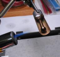
In the photos, the screwheads were polished with 800 grit emery paper, and then blued. I ended up giving a higher polish to almost all of the screws and especially the more prominent screw heads. I used a makeshift bluing setup that is simply a piece of brass tubing held in the third-hand of the soldering station. It was heated with a small butane torch and the screw removed with tweezers once the desired color is achieved and quenched in a small jar of oil. "Bluing" is usually a manifestation of tempering hardened steel to a blue color that is usually the spring state. However, in this case I doubt the steel is hardenable and I am simply heating the screws to achieve the blue color for purely cosmetic reasons. Obviously, the screws could have been used as purchased, with their zinc-plating intact, but the blue color will contrast nicely with nickel plating of the finished key.
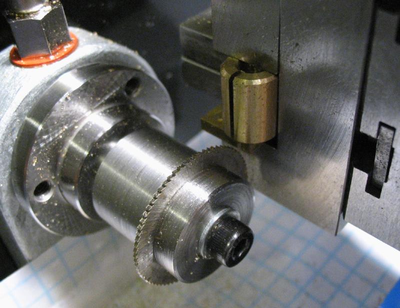
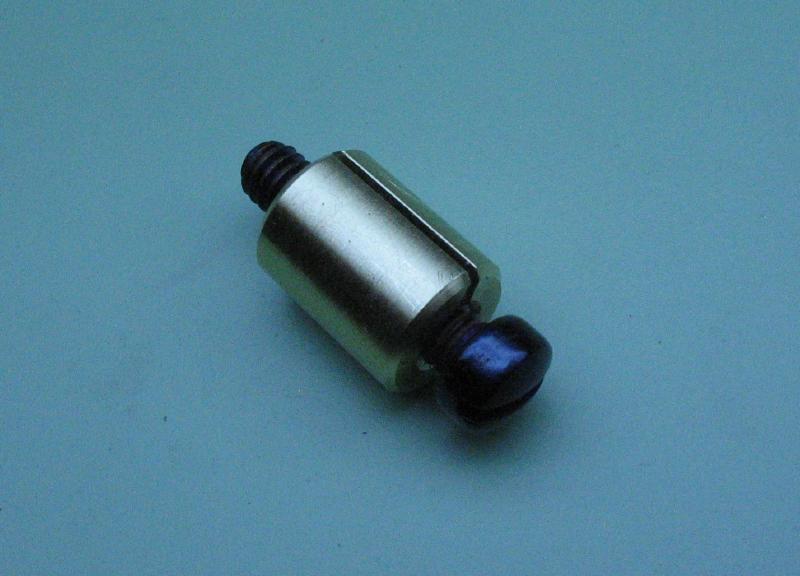
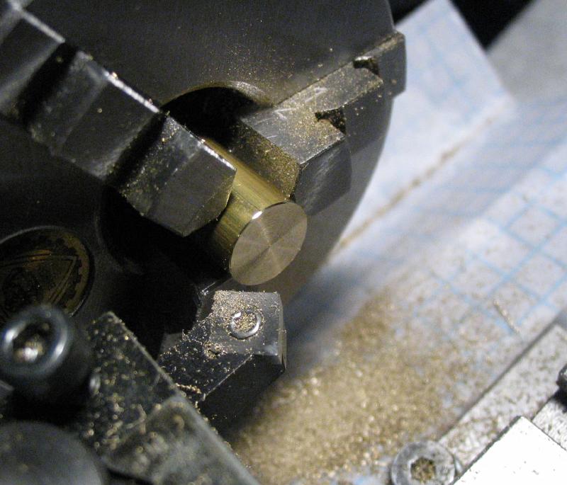
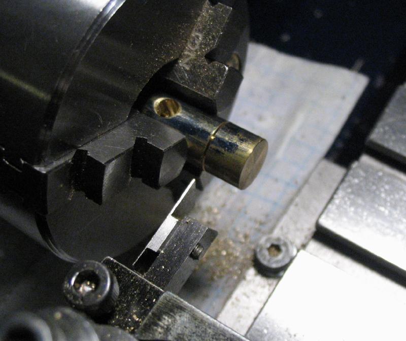
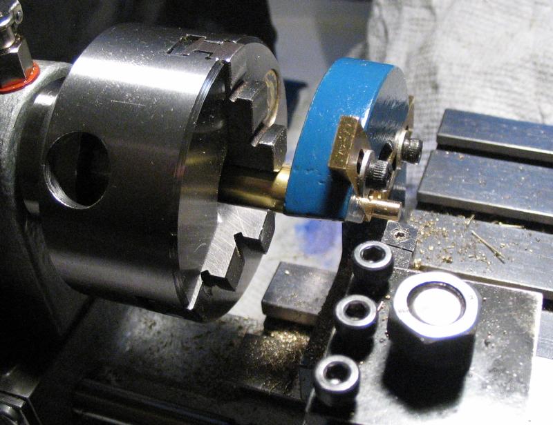
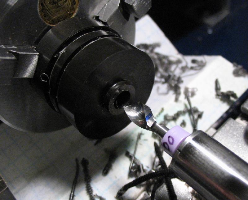
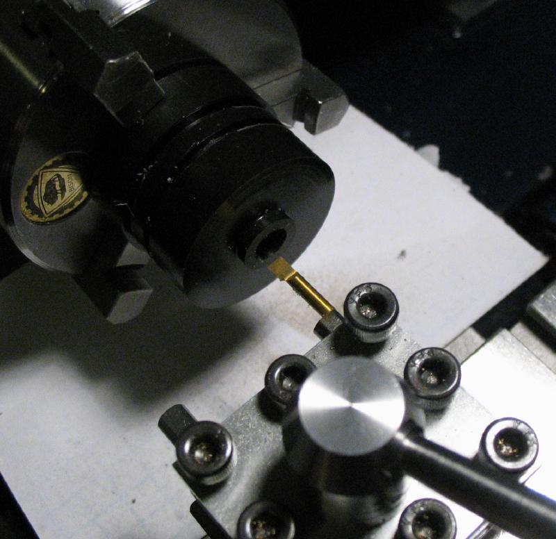
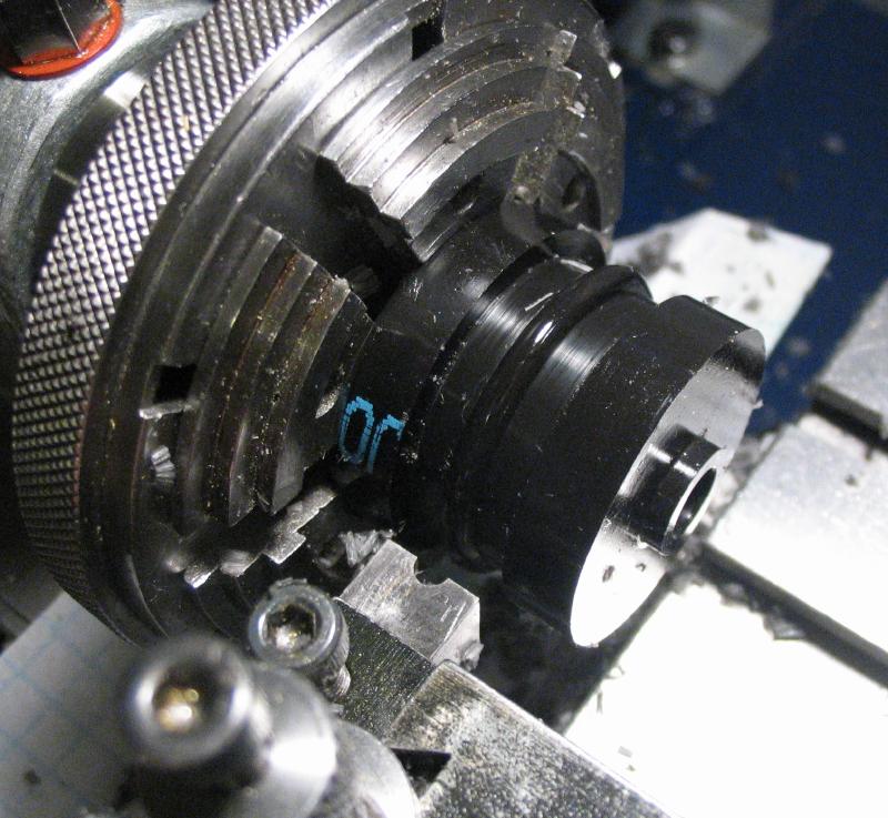
In order to make alterations to these screws, a threaded clamp was made to hold them in the lathe. A length of brass rod, just slightly larger in diameter of the screw head, was turned true and a section parted off. The parted section was then faced, drilled, tapped, and countersunk. It was then mounted in the machine vise and a slotting saw used to slit it down its length. A screw can then be inserted and the slit allows it to be clamped tight in the 3-jaw chuck. I found that the finished clamp retained a fair amount of spring strength, and required excessive tightening in the 3-jaw chuck to secure the work sufficiently. It was annealed by raising it to red heat and quenching in water. This leaves the brass quite soft and will clamp the screws while requiring much less pressure.
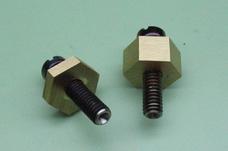
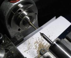
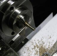
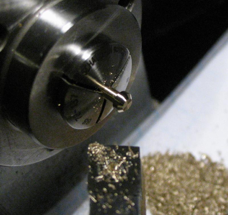
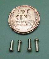
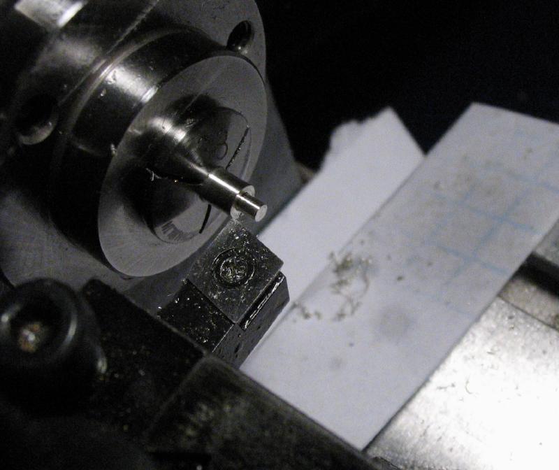
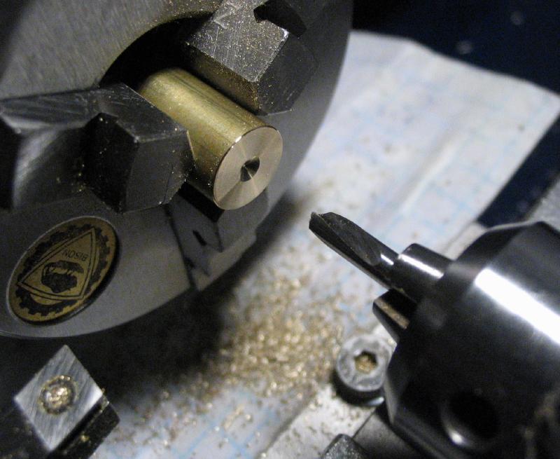
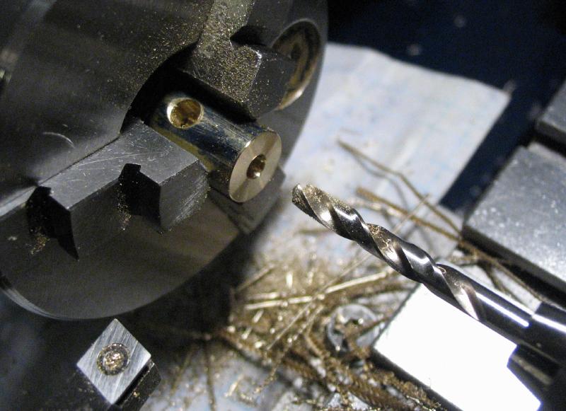
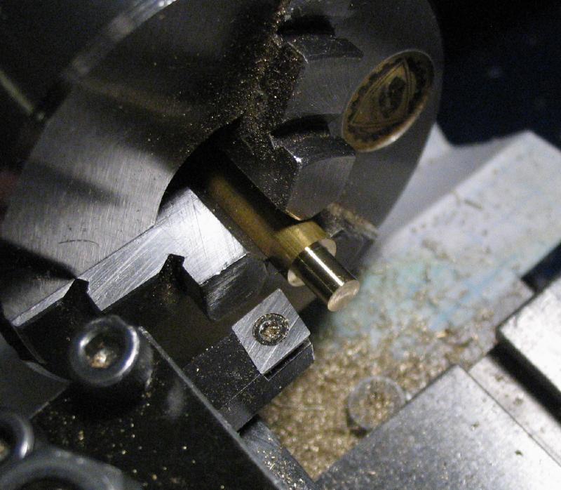
Two of the blued fillister head screws were mounted on the lathe and their tips faced and drilled with a combination center drill / countersink. This was a 000 size drill, and the hole was enlarged to 1mm afterward. These screws will be the pivot bearings for the pendulum bar arbor. Vibroplex's deluxe models use jeweled bearings, which I briefly considered using something similar in this key, but the modified screws and coned steel arbor is not only very simple to make but seems to work well and is very easy to repair or replace parts if needed.
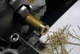
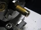
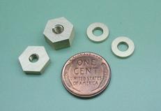
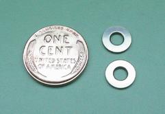
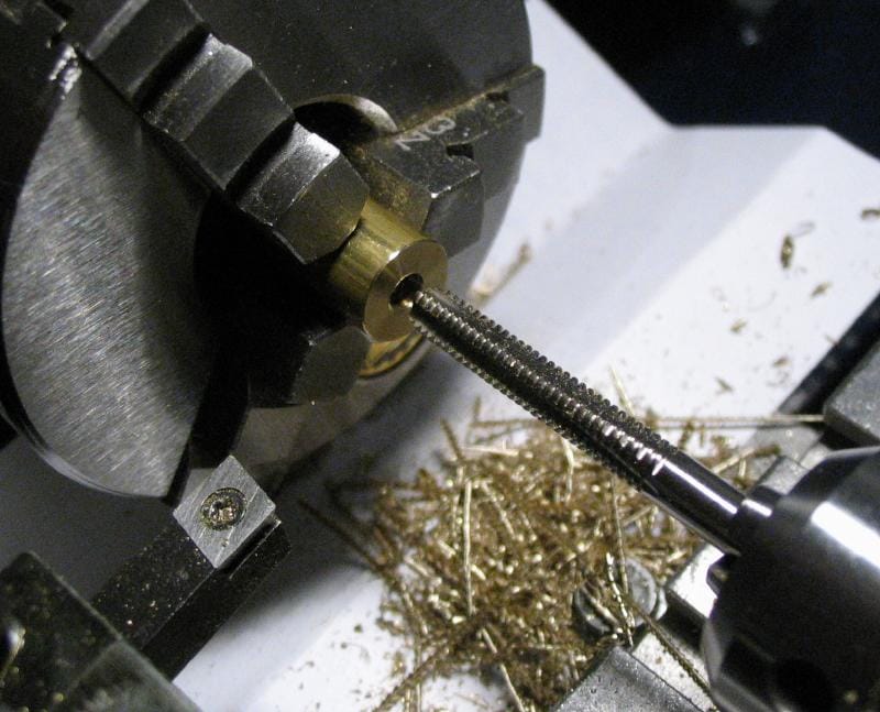
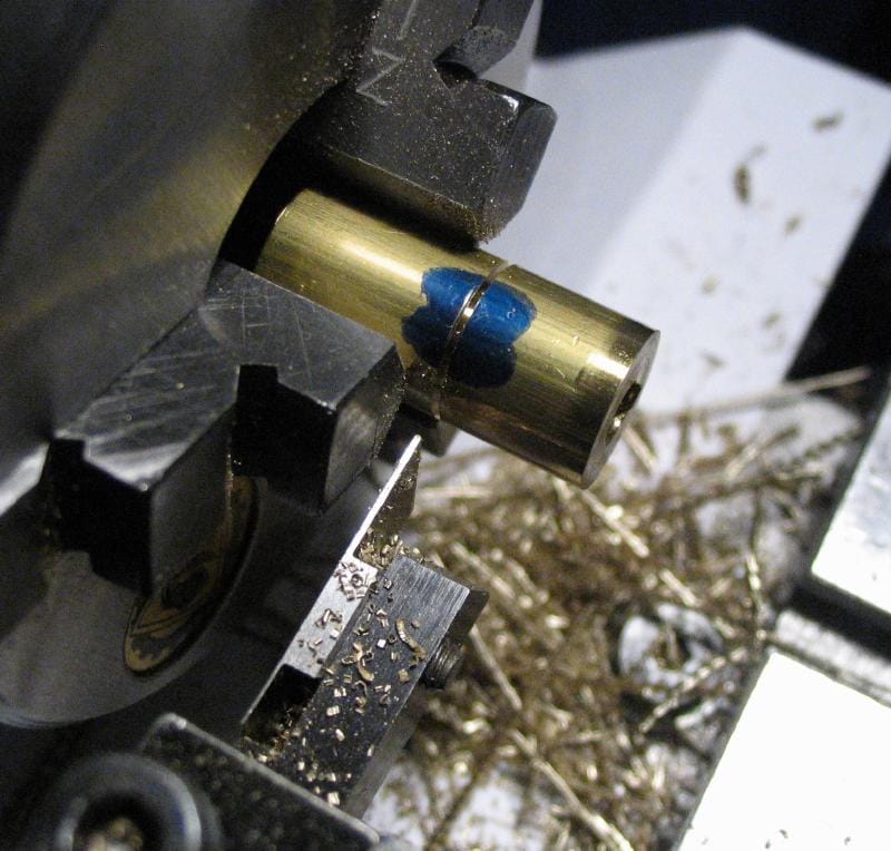
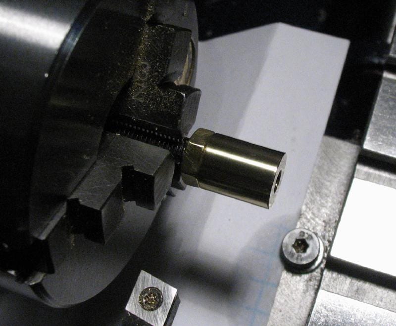
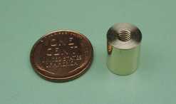
Additional hardware was made, some of which may only be temporary but will allow the components to be assembled. A pair of nuts were made from hex brass rod, which is faced, drilled, tapped, and two different widths were parted off. A pair of washers were made as well, these being made from brass round rod, turned true, drilled with a clearance drill, and thin sections parted off.
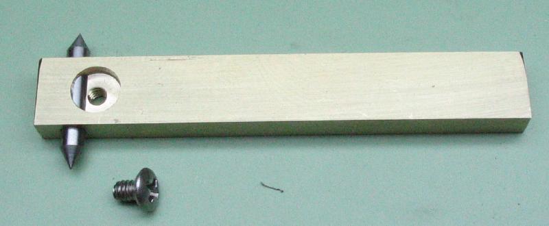
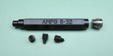
The location of the screw positions for the bridge in the mainplate can be ascertained by inserting centers into the threaded holes of the bridge and marking the desired location. A handy tool for doing this are called transfer screws. Although something similar could be made, these are available in the usual thread sizes and include a handle that is both a storage compartment and the tip of which serves as the hex driver for inserting and removing the threaded inserts. The threaded inserts have a hex portion and a sharpened center point. They were screwed into the base of the bridge and the location chosen on the mainplate.
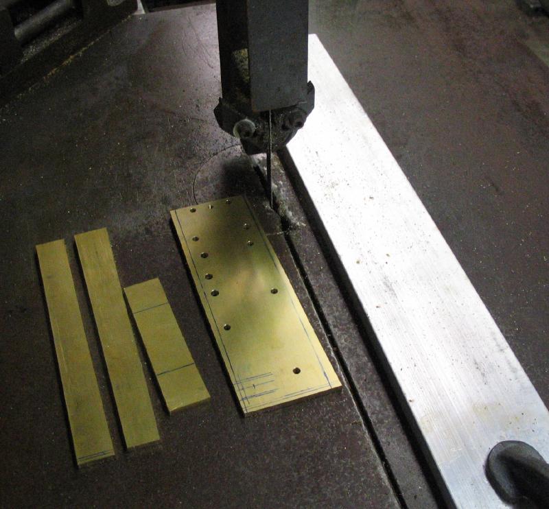
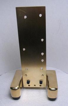
The mainplate is made from leaded brass plate (type 360); it was purchased in the required thickness and the recommended starting length directly from a metal supplier (many metal dealers offer cut-to-length service). It is about 1/2" wider than suggested, but this was the closest size available. It is a fairly large piece of brass, so I wanted to keep waste/surplus to a minimum. The final dimensions are cut down to size near the end of the key's construction, so there will be some waste. In retrospect, one could start with a plate of the final dimensions as there was not much advantage to starting with a oversized piece of brass.
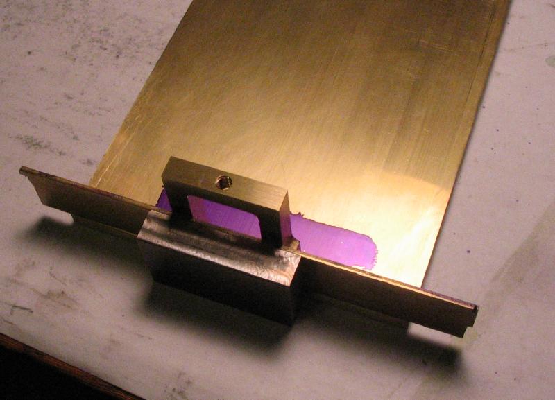
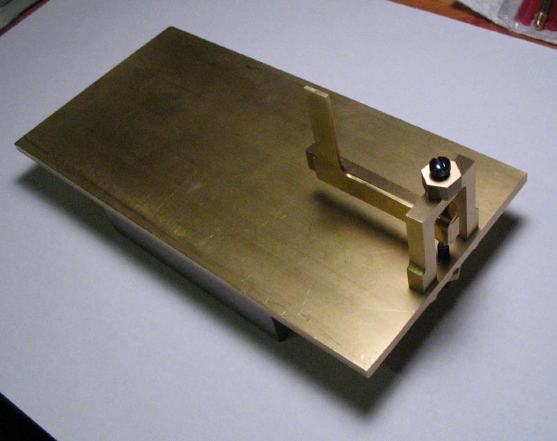
The bridge was located in the middle of the plate and about 1/16" from the edge. Mr. Smith states that it should be flush with the edge, but his photos suggest otherwise. This may be to allow for squaring the edge of plate off later on. As can be seen in the photo, I used the steel block made above against the edge of the plate for reference and a length of brass strip inserted as a spacer to position the bridge an even space from the edge. The bridge is held steady, balancing on the center points and is then given a healthy whack with a mallet. The transfer screw centers will leave the locations for drilling in the next step.
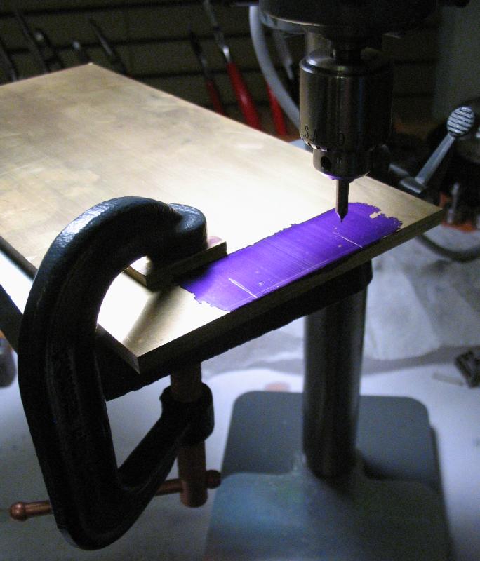
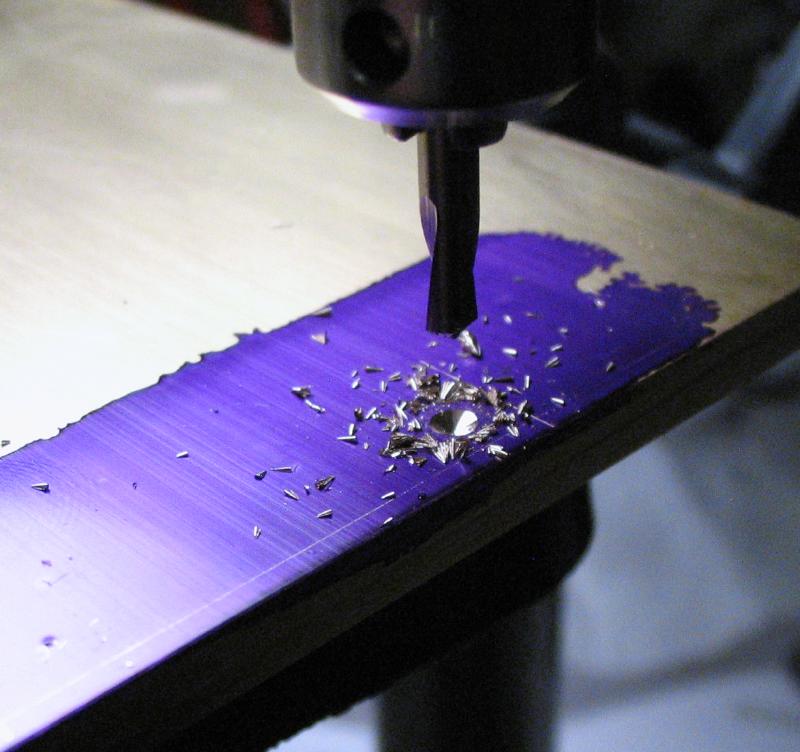
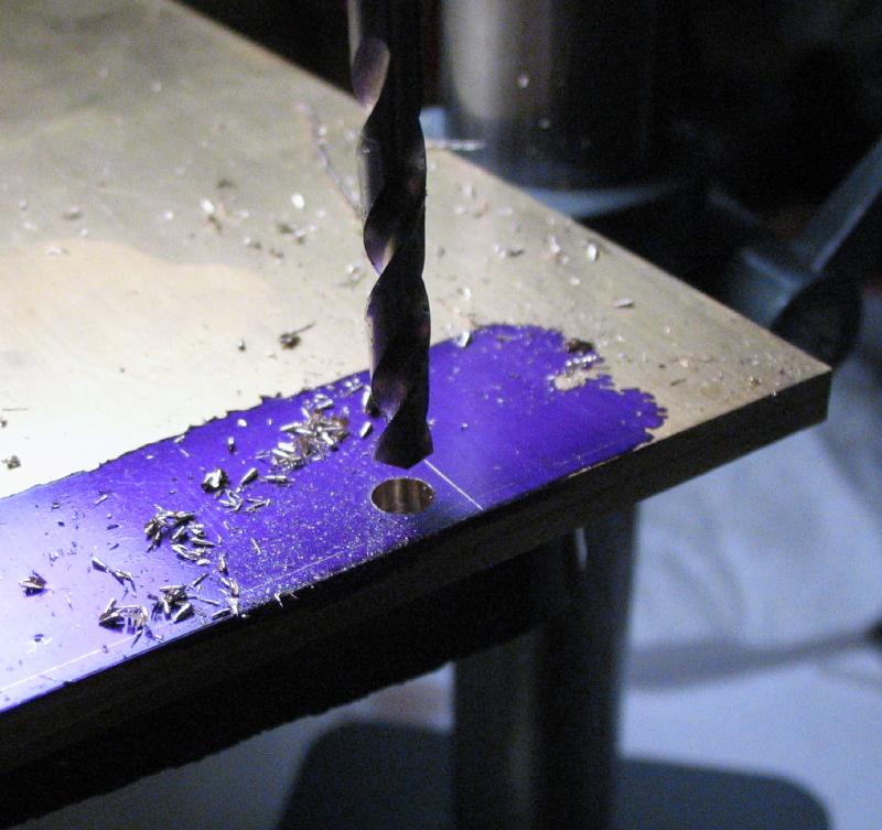
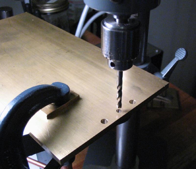
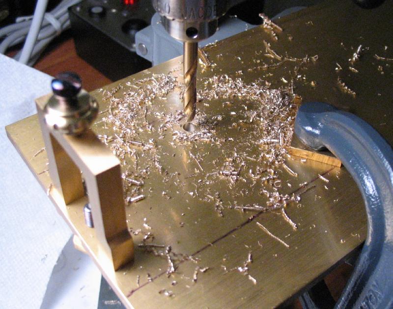
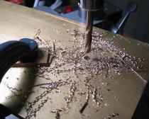
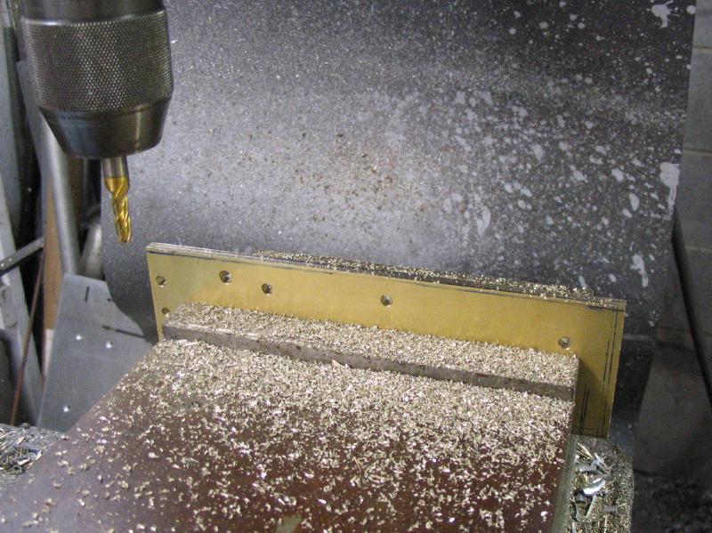
The plate was clamped to the drill press table and the punched locations found with a center-countersink drill. The work is obviously a little large for the Cameron drill, but workable setups were found with the plate overhanging the drill press's table and a C-clamp securing it into place. The position was spot drilled and drilled to pass the screws. The second location was then drilled in the same manner. The holes were finally deburred with a jeweler's setting bur.
I purchased one size length of the fillister head screws to use in making this key, but in some cases these may need to be shortened to fit. The bridge screws needed to be shortened, and this was done on the lathe with the screw clamped in the headstock and the unneeded length parted off with the rear tool post. Mr. Smith does not appear to use washers, but at least for now, I decided to include the brass washers made above.
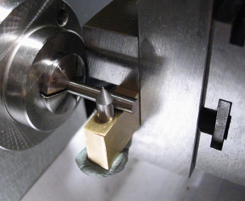
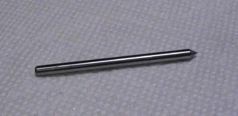
The position for the lower pivot screw was found using a special made center punch. A length of drill rod that is the same diameter as the tapping drill was given a 60 degree point and mounted in the drill press chuck. The drill press provides a means of keeping things upright, and the punch is fed through the pivot screw hole in the bridge and the lower position marked with light taps using the drill press quill. The bridge is removed and the center position was located and drilled for tapping.
The lower pivot screw can be installed with the bridge and the paddle assembly tested for a rough fit as well.
The springs for the pendulum return and paddle-knob return, as well as the latter's knurled nut, were purchased directly from Vibroplex. The nut would be fairly simple to make. Mr. Smith mentions making the pendulum return spring, but does not give any details on this topic, including what size wire to use. In addition, he does not discuss the source of the paddle-knob spring. The spring wire measures about 0.5mm.
The specified location for the paddle-knob return spring screw was scribed onto the pendulum bar and found with a center punch. The position is drilled through both bars with a tapping drill. The bars are separated and the paddle-knob bar was tapped for the screw. The pendulum bar was drilled open with a generous clearance and then counterbored with an endmill for retaining the spring.
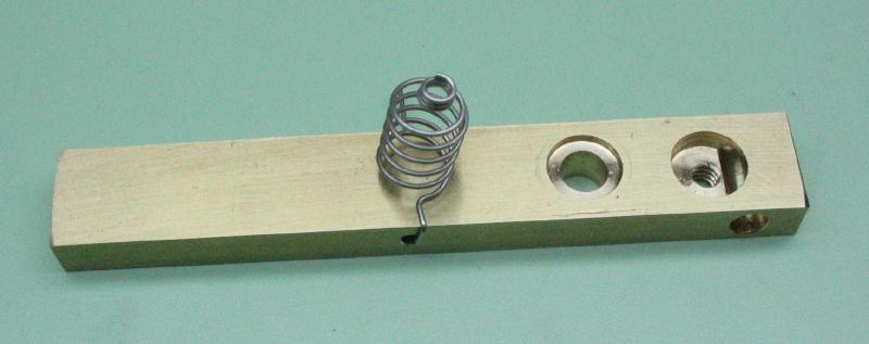
The pendulum return spring attaches to the pendulum bar through a hole that is laid out and drilled through. The spring will eventually be inserted into this hole and its end bent over to secure it in place, but there's plenty more to do before making this permanent.
The 'magic hole' - that is the term Mr. Smith uses - is a hole in the paddle-knob bar that allows a stop screw to pass through to the pendulum bar. There is some confusing information in his book, including the measurement given and the photos that show how the location is found compared to the photo of the actual drilled location. However, I think there is some freedom here, and is more important that the screw be aligned with where ever the hole is located (this will be done later on). I decided to place the hole centered in the intersection of the two arms of the bar. This was scribed and setup for drilling through.
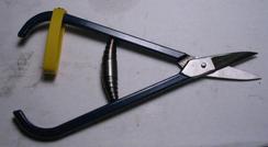
The pendulum mainspring was made from stainless steel 'feeler' gauge. It can be purchased in the required thickness, and the desired shape was scribed onto the surface and I then cut it out using my solder shears. This was a bit of a struggle to cut, so I would recommend shears or snips with a little more cutting-power. The edges of the spring were then smoothed using emery paper.
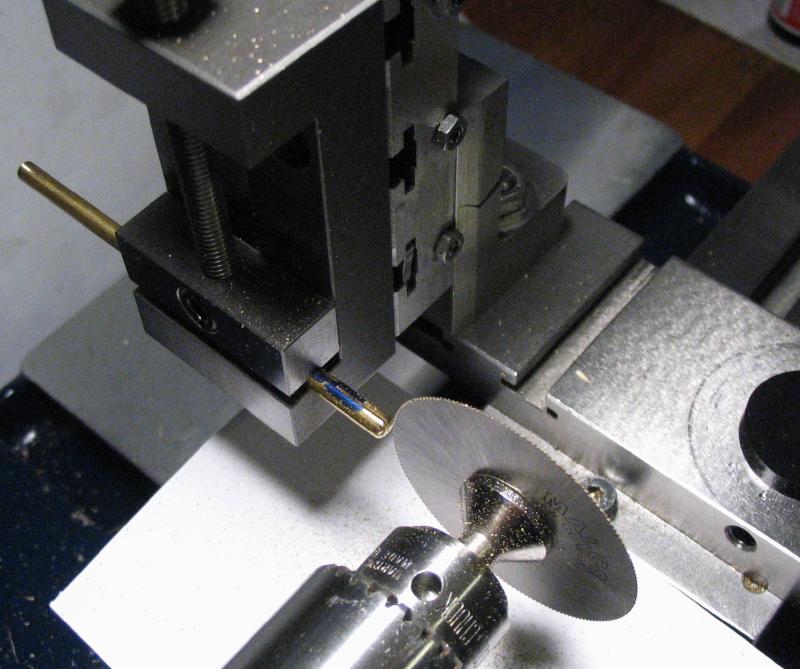
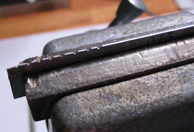
The pendulum weight rod is started from a specified length of brass rod. It was cut to size and the ends rounded over with a graver on the lathe. One end of the rod was then slotted to accept the mainspring. It was mounted in the machine vise and vertical slide of the lathe and cut with a circular slotting saw that is a couple thousandths of an inch thinner than the mainspring. To open the slot to fit the mainspring, a few teeth are cut into the edge of the stock feeler gauge using a half-round needle file. This can be used to open the slot in the weight rod to give a very snug, final fit to the mainspring. The pendulum bar is also slotted in the same manner as the weight rod to accept the other end of the mainspring. Both the weight rod and the pendulum bar are drilled through to accept rivets that will secure the mainspring in place.
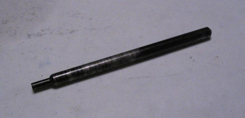
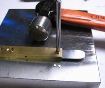
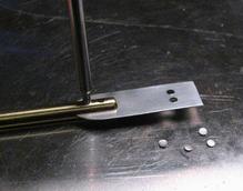
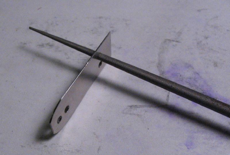
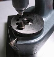
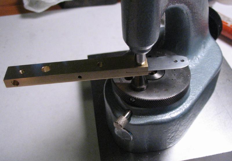
The rivet holes in the mainspring must be punched out. This requires a custom made punch made from oil-hardening drill rod that is faced, turned to fit the rivet holes and then fully hardened by heating to cherry red with a torch and quenching in oil. I stoned the surface of the turned diameter of the punch on the lathe with an Arkansas slip stone, but did not attempt to stone the cutting face. The assembled mainspring and bar or weight rod are placed on a bench anvil and the punch driven through the mainspring with a hammer. The small discs of stainless steel that come through can be seen in the photo. The resulting hole in the mainspring is slightly smaller, but is brought to the required size with a round needle file.
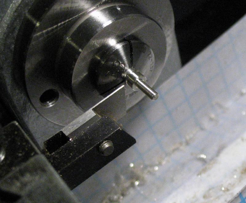
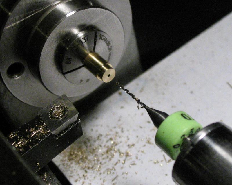
The rivets were made from brass rod. The rod was held in a collet in the lathe and turned to fit the holes and to a length that extends through the pendulum bar or weight rod with enough on the other end to roll over. The end was center drilled to provide a rivet surface and then parted off. They were not installed just yet.
Gravers
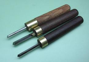
In various steps below, I describe machining by hand turning with a graver. I show the results, but forgot to photograph the gravers themselves. Below is a selection of the gravers used; they are made by the method Mr. Smith describes in other publications and extensively in his video on making and using gravers. I provide more details on making gravers on the toolmaking page. The top graver is made from 1/8" oil hardening drill rod, the face milled, filed flat, hardened, and stoned to a sharp face using a honing jig. The center graver was made following Mr. Smith's video closely, using a square 1/8" Mo-Max M33 high speed steel lathe tool bit, ground on a bench grinder and sharpened by hand on an India stone. The lower graver is a smaller version made from 3/32" GRS GlenSteel. The gravers are used by hand and held against a T-rest, which is shown in the photos when this technique is employed.
In various steps below, I describe machining by hand turning with a graver. I show the results, but forgot to photograph the gravers themselves. Below is a selection of the gravers used; they are made by the method Mr. Smith describes in other publications and extensively in his video on making and using gravers. I provide more details on making gravers on the toolmaking page. The top graver is made from 1/8" oil hardening drill rod, the face milled, filed flat, hardened, and stoned to a sharp face using a honing jig. The center graver was made following Mr. Smith's video closely, using a square 1/8" Mo-Max M33 high speed steel lathe tool bit, ground on a bench grinder and sharpened by hand on an India stone. The lower graver is a smaller version made from 3/32" GRS GlenSteel. The gravers are used by hand and held against a T-rest, which is shown in the photos when this technique is employed.
Contacts
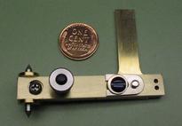
A pair of contacts were made, one is the dash contact for the semi-automatic key and a second contact was made to act as a dot contact for paddle-key use. The contact plate is made from thin brass plate (type 353 is used here). A starting hole for the screw slot and the hole for the silver contact were laid out and drilled. The slot is cut out and plates brought to shape by sawing. A note to Mr. Smith's book: he provides a dimensioned drawing that does not match what he shows making. He notes the difference and states that the design was improved upon, but is not explicit which one is the improvement, the drawing or the one made. I assume the drawing is the improved version, however, at least one of the dimensions in the drawing is incorrect, which becomes obvious while trying to scribe it out on the brass plate. However, the part is straightforward enough to proceed. A pair of washers were also made from brass rod by turning true, drilling and parting them off.
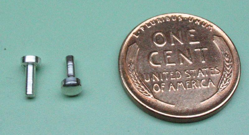
The actual contact is made from sterling silver rod, and turned to shape on the lathe. Silver is an excellent conductor, which is why it is chosen for this purpose. A short length of sterling silver wire was held in a collet and turned down to fit the hole of the contact plate with a little extra length protruding on the other side. The end is drilled and this will provide the rivet later. The contact is parted off, and the parted face given a slightly convex shape.
Before the contacts can be installed into their plates, the plates need to receive their nickel plating since the silver needs to be exposed and once installed they can not be removed without damaging them.
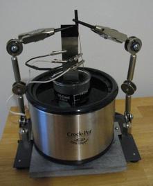
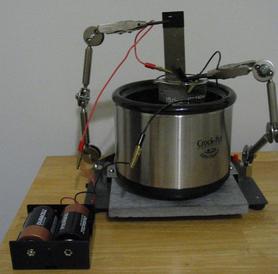
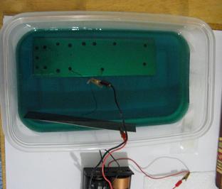
Described below is my initial setup for electroplating parts with nickel. The setup consists of a heated water bath, which is a small 'crock pot' that is not adjustable but keeps steady at about 132 degrees Fahrenheit, a beaker containing the nickel plating solution, a nickel anode, a power supply, wires for connecting everything up, and, of course, the part to be plated, which acts as the cathode. The power supply is an old AC to DC adapter that supplies 1.5 DC volts at up to 0.7 amperes, but this choice was a matter of convenience. Mr. Smith recommends a resistor be added, so a 470 ohm (1 watt) carbon film resistor was soldered between two lengths of insulated wire, which was then sealed with heat-shrink tubing and the wires given alligator clips at their ends. This wire jumper is connected between the leads of the power supply and intended to prevent prevent power surges that can adversely affect the plating quality. The pure nickel anode and Midas brand bright nickel electroplating solution were purchased from Rio Grande (jewelers supply). According to the MSDS, the Midas nickel solution is 10-20% nickel sulfate, 1-5% nickel chloride, and 1-5% boric acid, and according to the catalog description, contains other additives that enhance plating quality. There are many recipes and instructions to be found online to formulate similar solutions, and the Midas solution is fairly similar to what is known as Watts nickel plating solution. The instructions include a recommendation to heat the solution, which is why I chose to place the solution into a hot water bath. I am using the clamps on the soldering station to assist in keeping everything steady (some insulating tape was used to prevent the clamps from shorting the circuit). The part to be plated is connected to the negative lead of the power supply with a length of copper wire and the nickel anode connected to the positive lead.
Plating proceeded very slowly using the 1.5 Volt wall wart and the results were not spectacular and needed to be polished afterwards to improve the finish.
I made various minor changes to the plating setup as I plated other components of the key below, I found the 1.5 volt 'wall-wart' power supply to be too slow to plate with or without the resistor-jumper. I later used two D-size batteries, which seemed to provide plenty of power to plate very quickly. Two D-cells provides three volts, which agrees better with the label on the Midas plating solution that recommends 2-4 volts. I also left out the resistor-jumper and continued to get much better results than above. However, the D-cells may be too powerful for some parts, and I experienced gas (hydrogen) formation which appear as bubbles on the surface of the part being plated and results in a pitted or cloudy finish. Constant agitation and stirring while plating helps reduce the effect of this. My method is fairly crude, but results were improved by washing the part to remove any residual oils, soap and fingerprints. Also removing oxidation on the surfaces helps. Each attempt was a slightly different experiment.
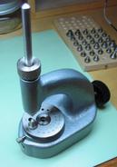
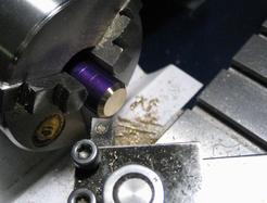
Once the contact plates have received their nickel plating, the silver contact pads can be permanently installed by riveting them into place. A special riveting stake was made from a length of drill rod (the diameter of the rod fits my Horia staking anvil). The rod was mounted in the lathe and its end turned using a graver to give it a slightly concave face with a small center point. This surface was polished using a small piece of cork and 3M Tri-M-ite papers. The stake was left in the annealed condition for use. The silver contact faces are rounded over, so a countersunk-type of stump was installed in the staking tool base to prevent flattening the face while riveting. The contact plate and silver contact are assembled and the riveting stake used to spread and roll over the back of the silver contact to secure it in place.
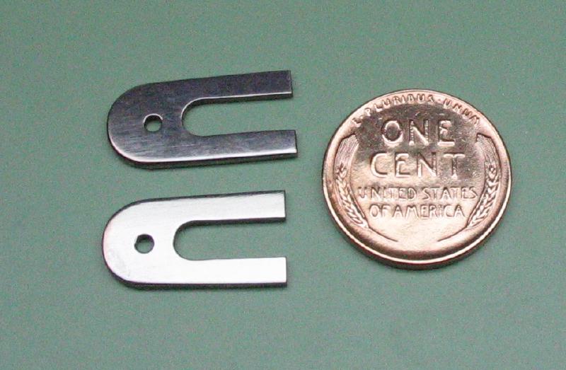
When deciding on the location for the extra dot contact plate on the pendulum bar, I discovered that it needed to be shortened a little in order to fit comfortably next to the spring. It was sawed and filed off, but will need some touching up in the plating bath. As will be noted below, I needed to make another contact plate that has a longer reach as well. The two final contacts are shown below.
The position for the screw that secures the dot contact was laid out, drilled and tapped. A screw was prepared as above and the threaded portion shortened to be slightly shorter than the thickness of the pendulum bar. I am working a little out of order, but I assembled the components made so far for a test fit, although the mainspring has not yet been riveted into place. The various stop, spring and contact screws will be made next, and their post heights will be made to match.
Screw Posts
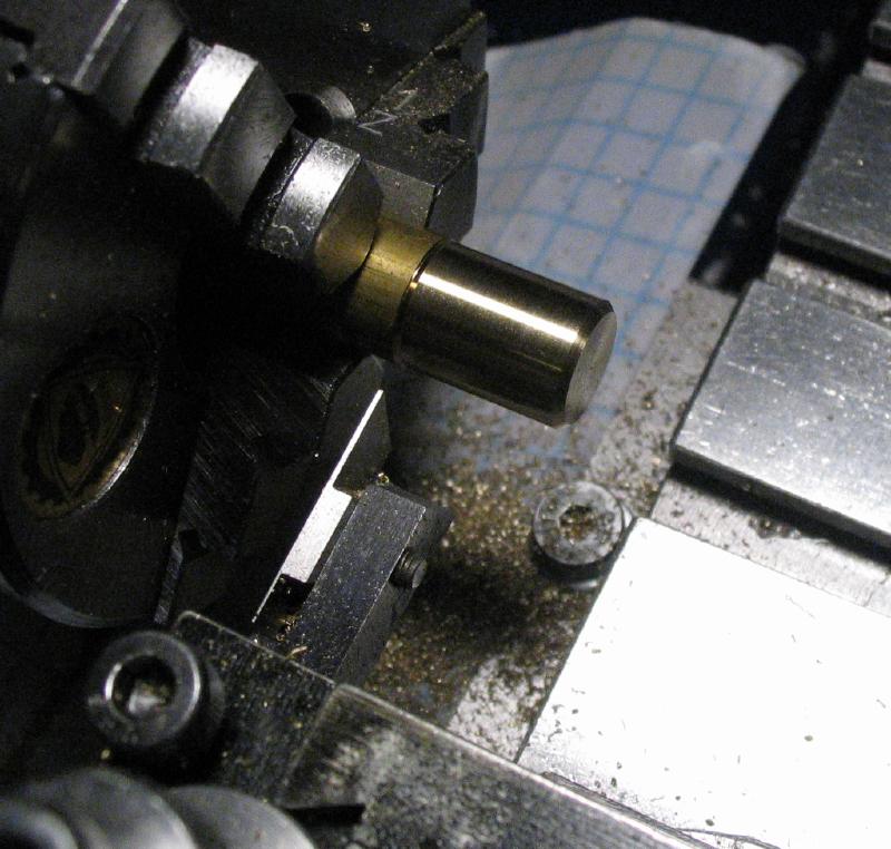
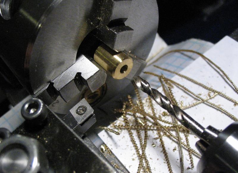
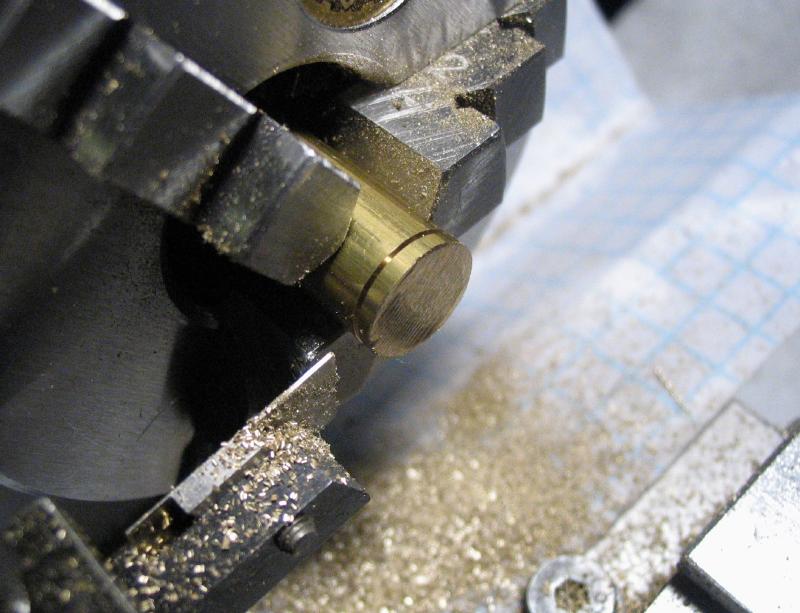
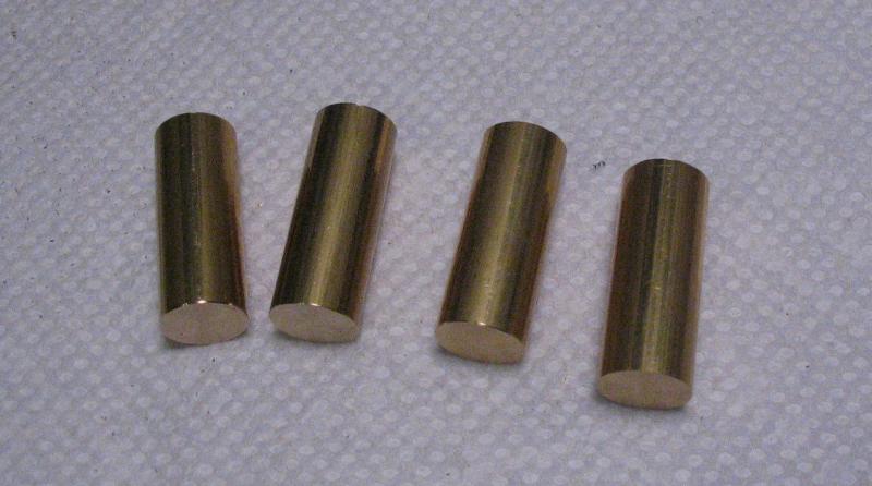
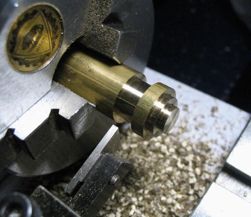
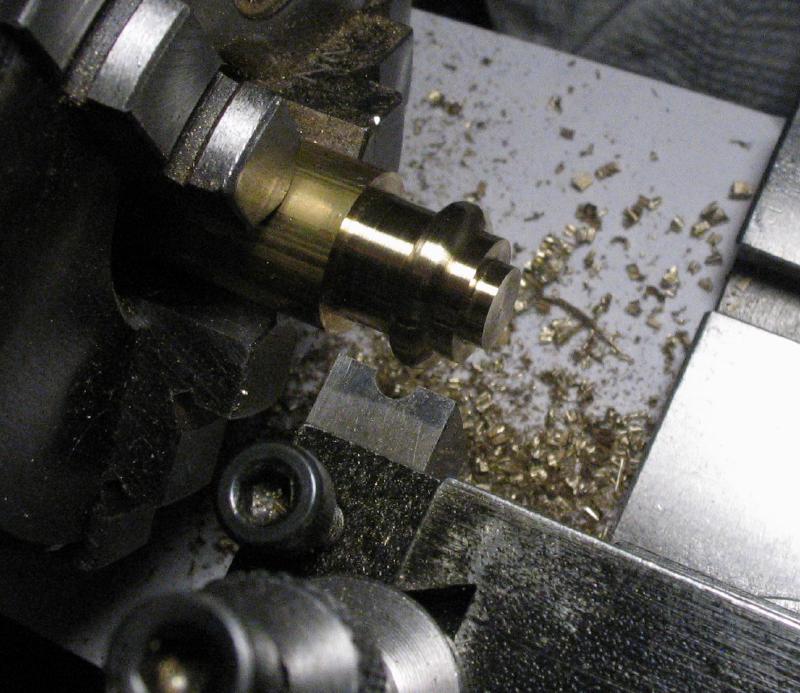
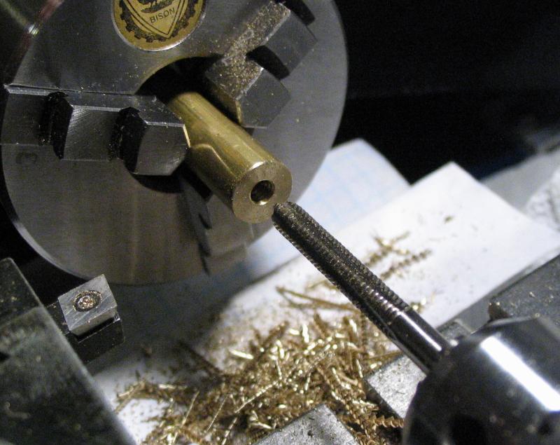
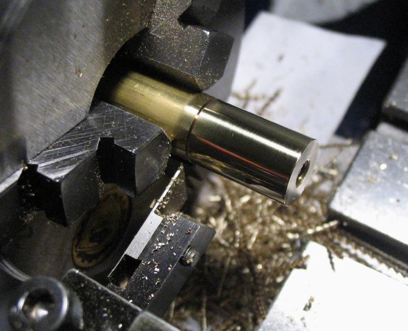
The posts for the various thumb screws are all the same starting dimensions and Mr. Smith demonstrates an arrangement for mass producing them. However, the diameter of the brass rod is too large to pass through the Cowells headstock, so I need to make them individually. A roughly measured length was sawed off on the power hacksaw, and one end faced true on the lathe. The rod can be marked for length with a pair of calipers and then parted off on the lathe and faced to the desired length.
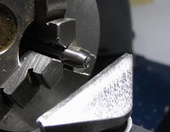
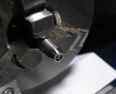
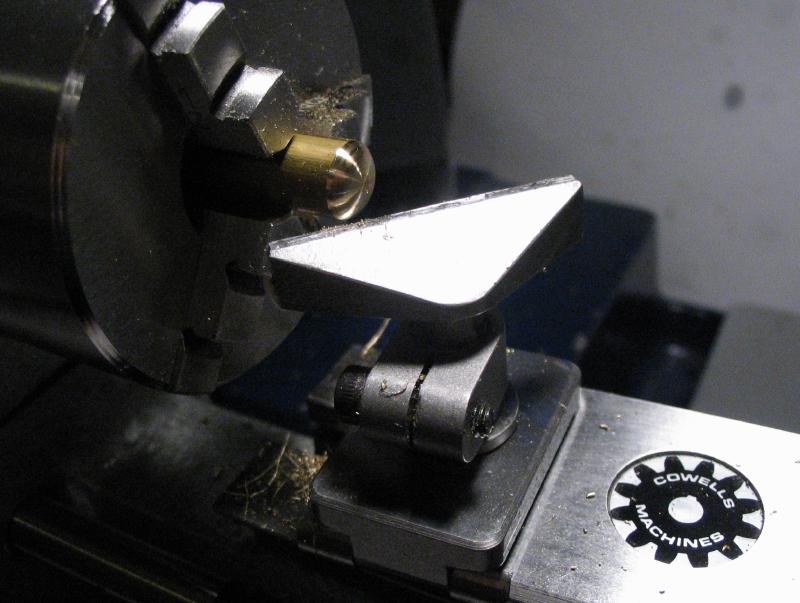
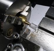
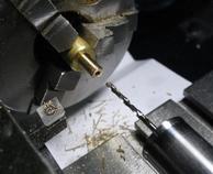
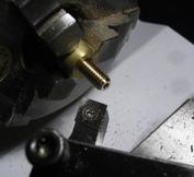
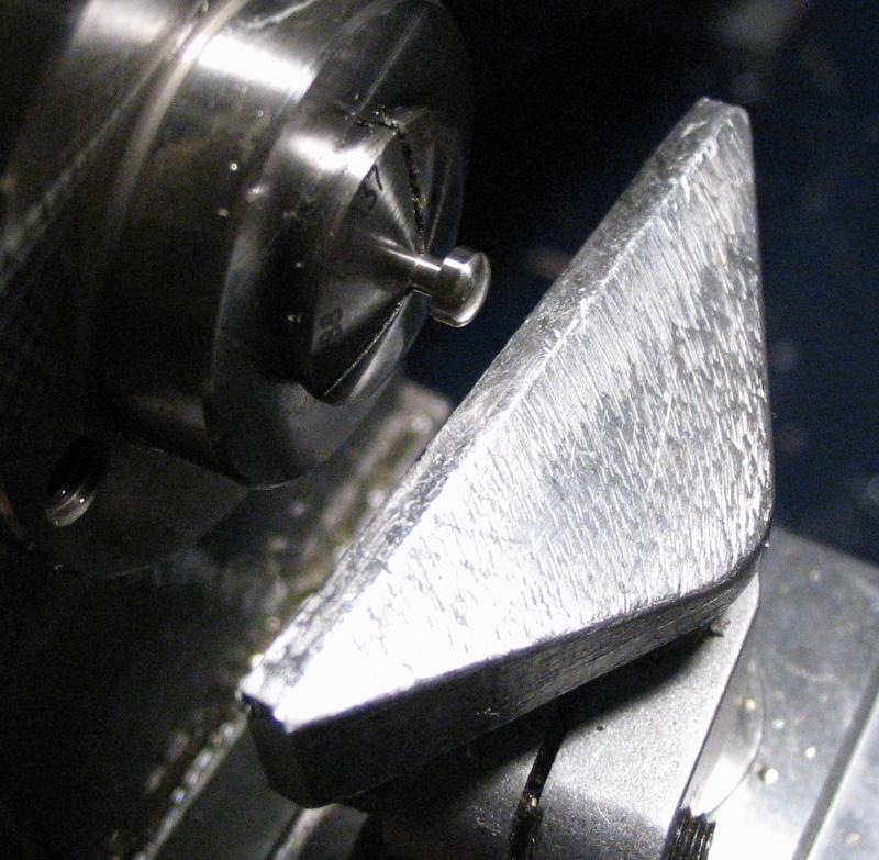
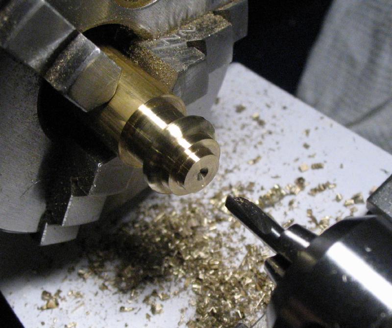
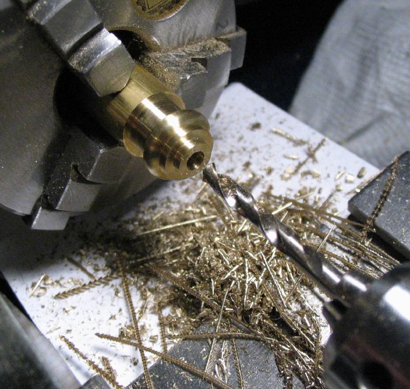
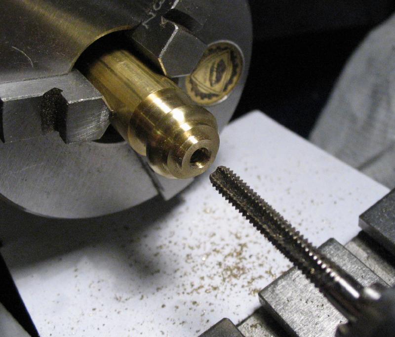
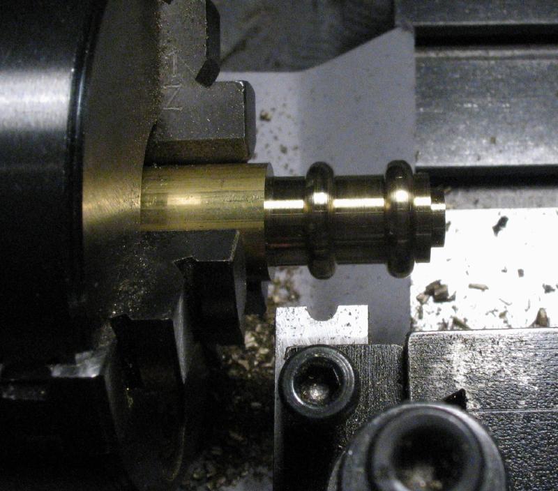
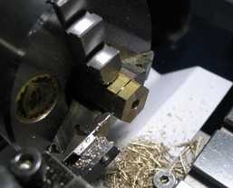
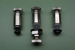
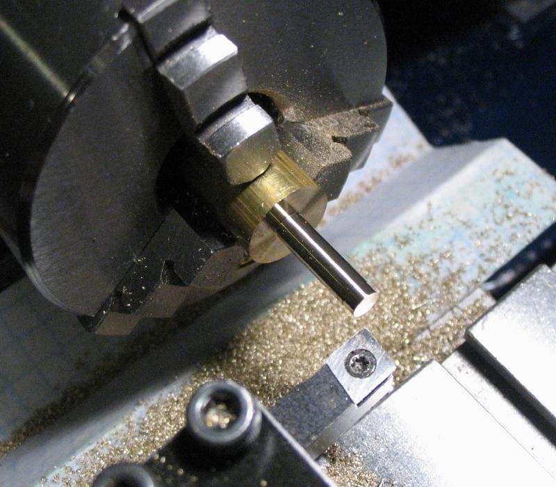
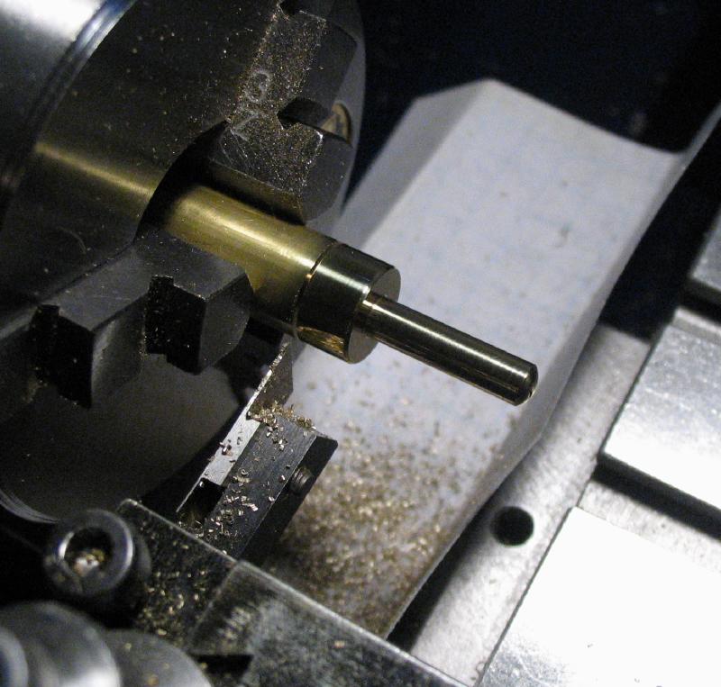
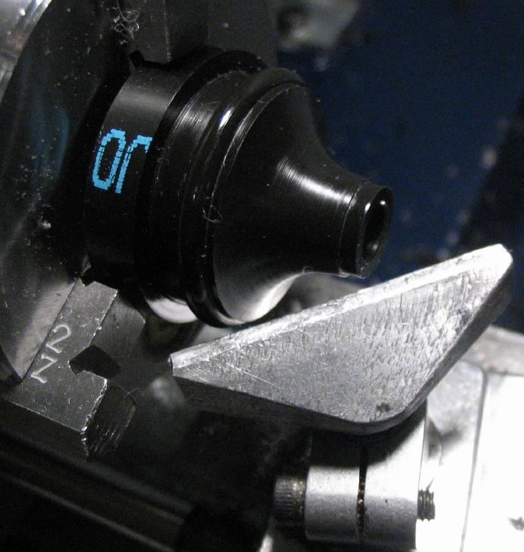
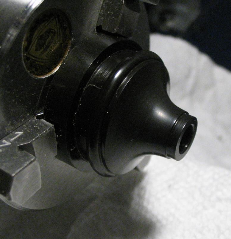
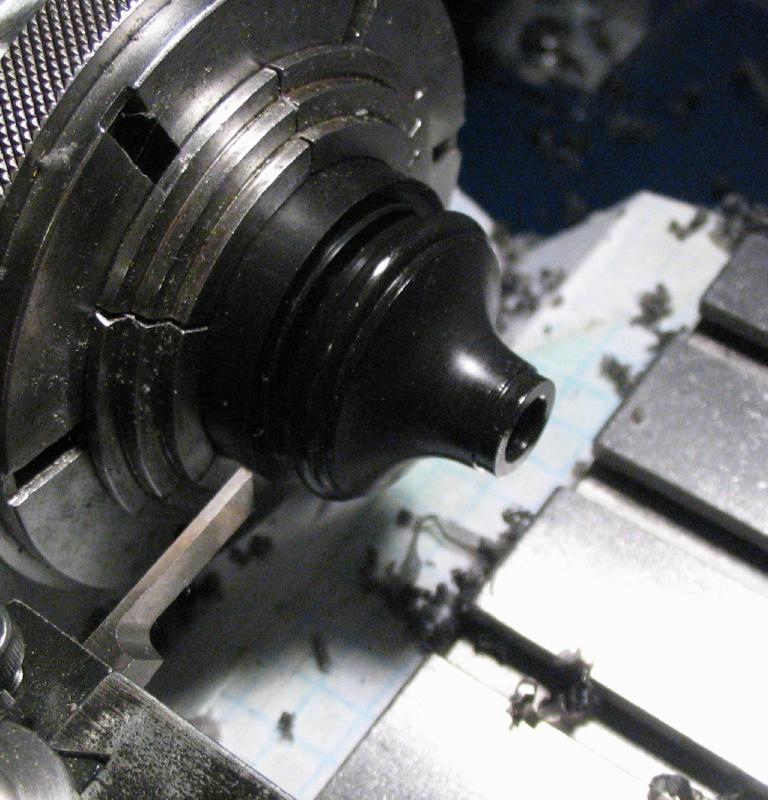
One end of the post was rounded over with a graver using the T-rest. Mr. Smith describes making a form tool for this step, which would produce more consistent results. The other end of the post is drilled and tapped.
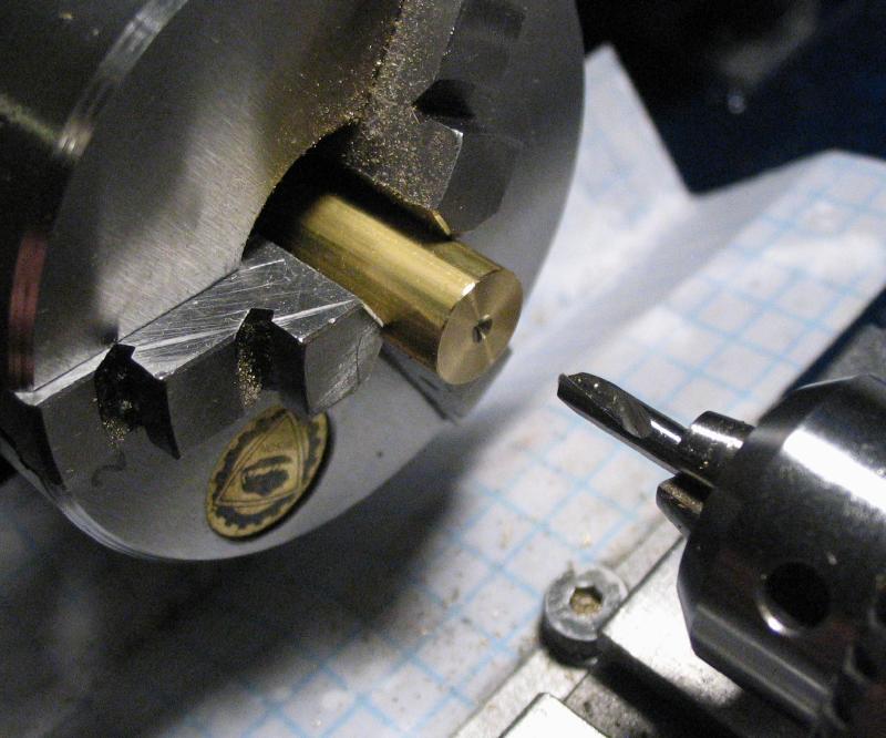
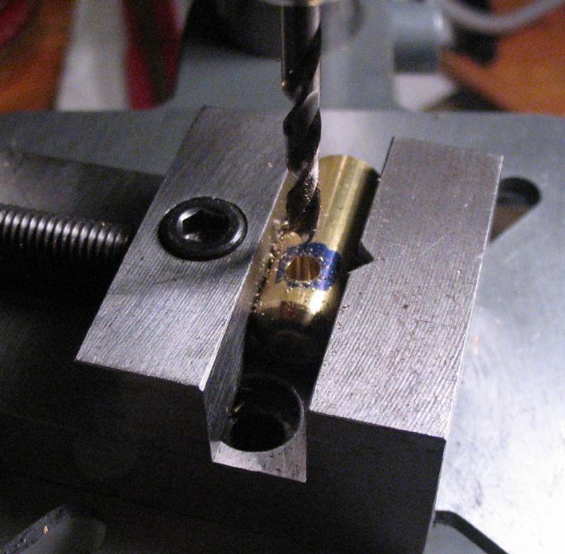
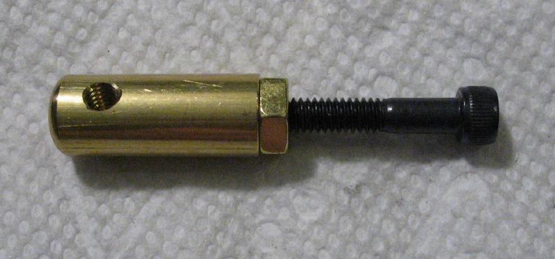
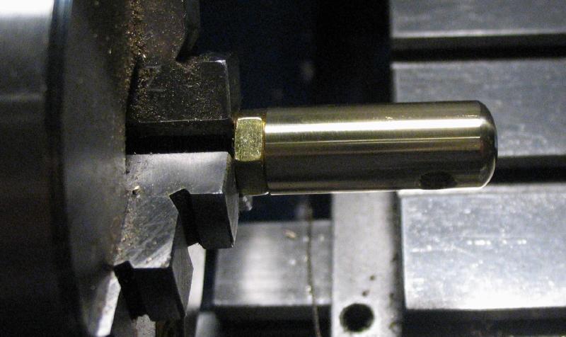
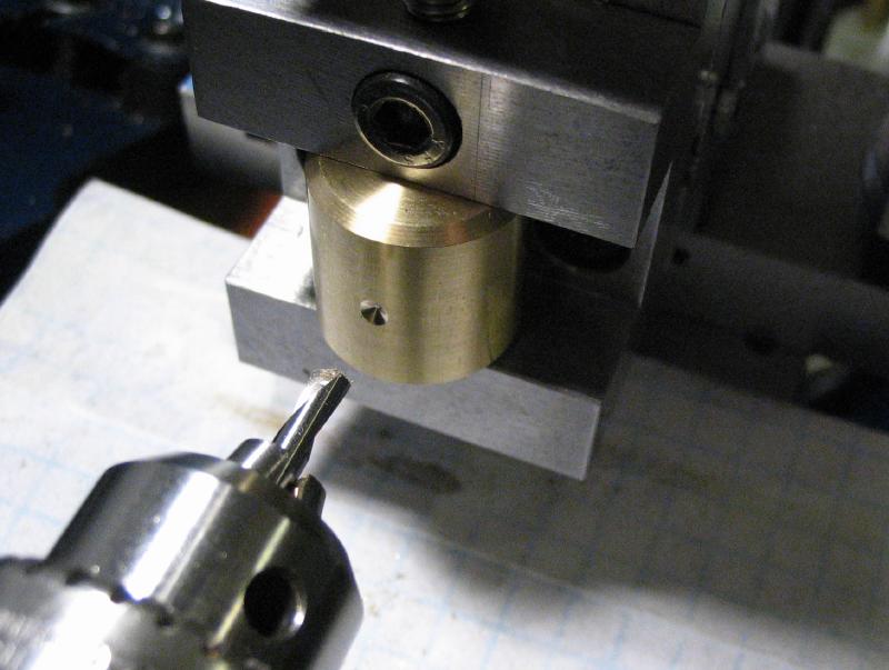
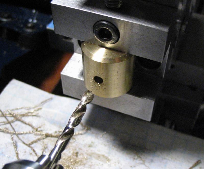
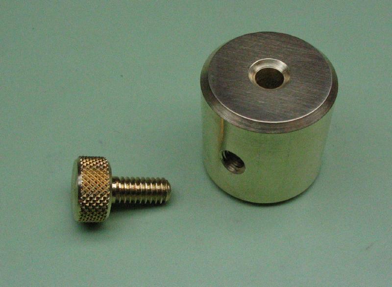
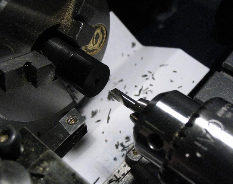
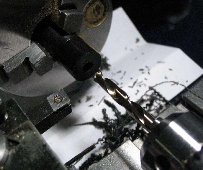
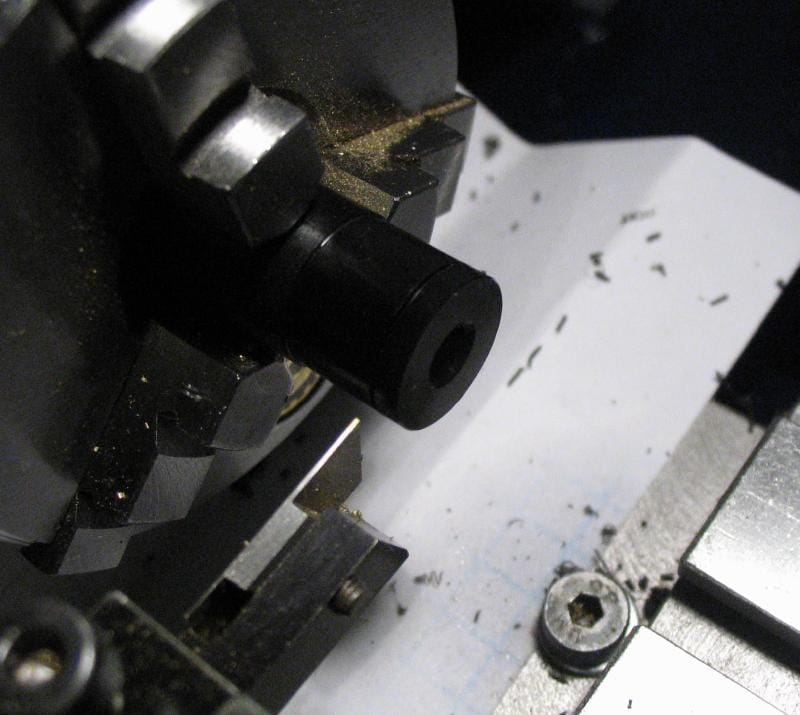
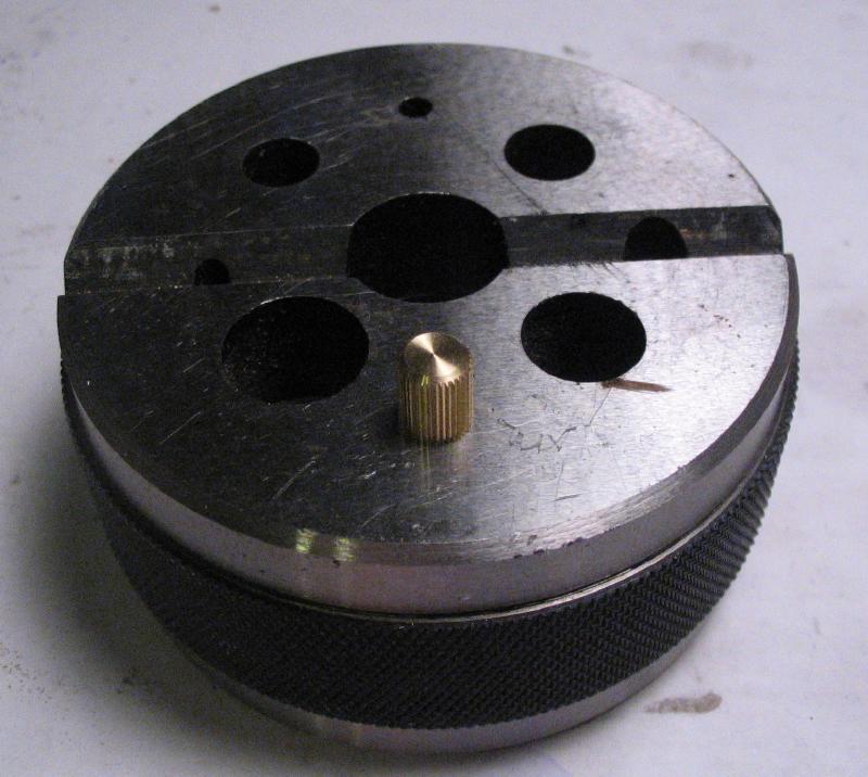
The posts are marked with a pair of calipers and then cross drilled and tapped for the thumb screws. A jeweler's setting bur was used to countersink the holes afterward. The surface of the posts was not turned, so they still have the rough stock surface. This was simply polished up on the lathe using a arbor constructed of a long socket head screw and a hex nut. The head of the screw fits behind the chuck jaws and will turn true enough to apply polishing paper to the post.
Set Screws
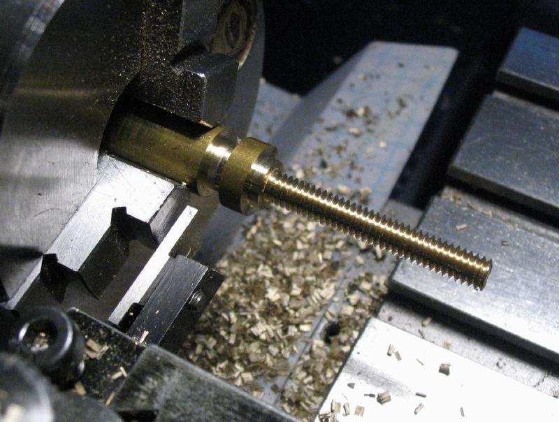
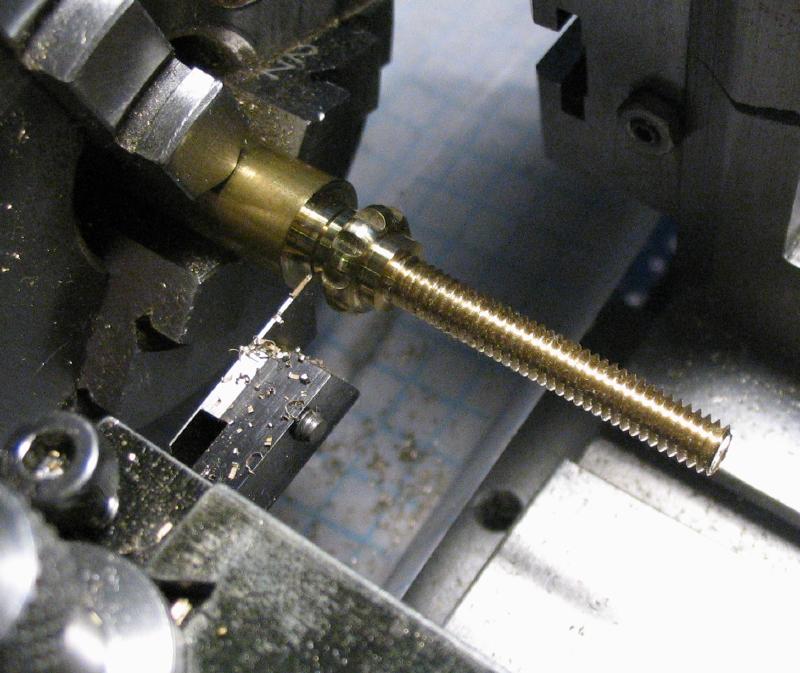
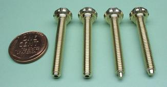
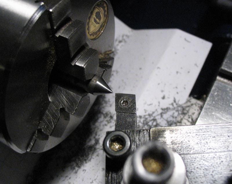
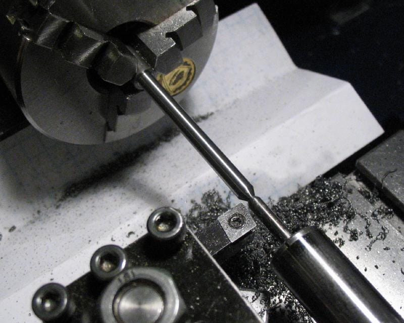
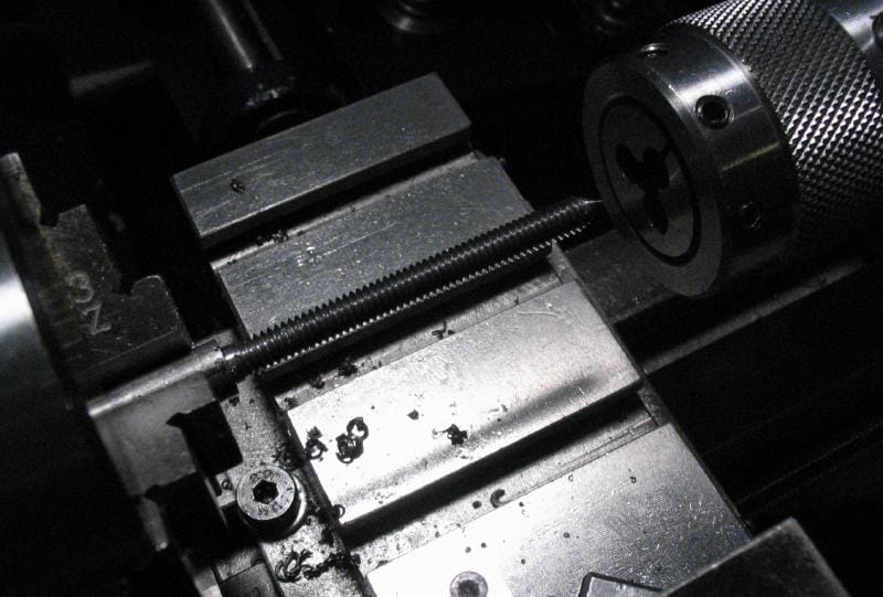
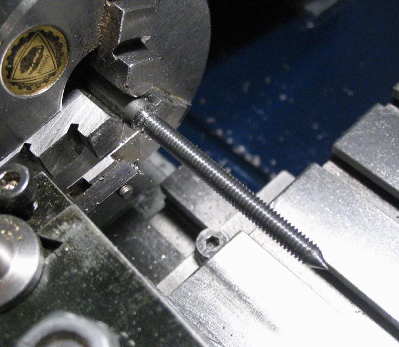
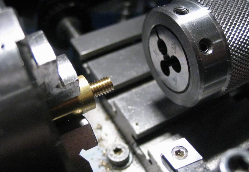
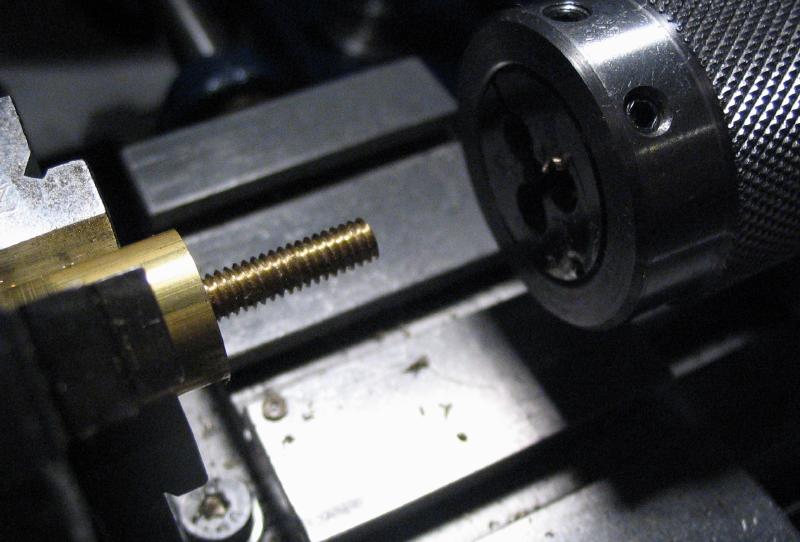
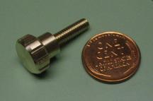
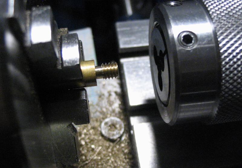
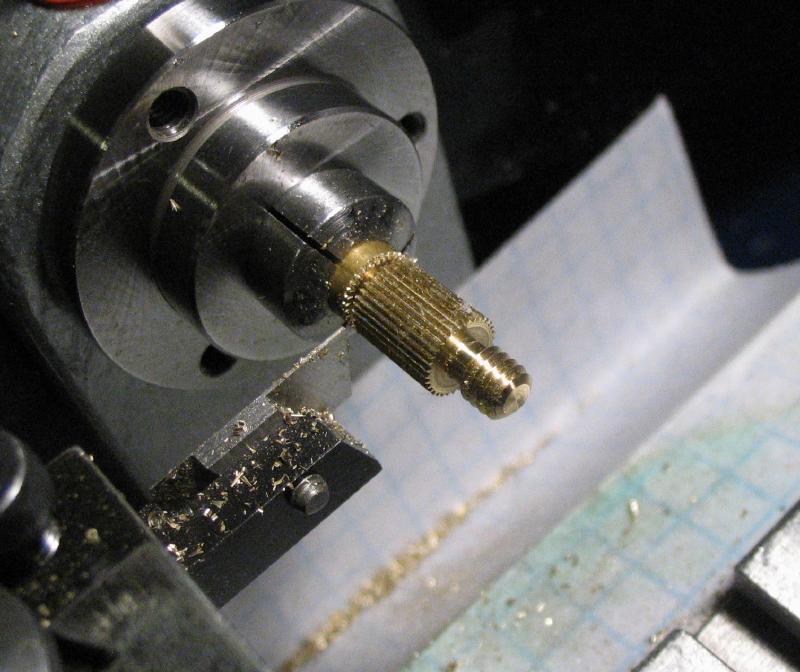
The thumb screws are made from brass rod, and the relatively long length and small diameter is difficult to turn since the rod will flex under the pressure of the cutting tool. On a larger lathe the cut can be made in one pass. Instead, I used a traveling-steady rest which minimizes the flexing and the brass can be turned true. The rod is turned slightly undersize since the finished screw will be nickel plated later, which adds to the final diameter. The rod was threaded with a die held in its tailstock-mounted holder.
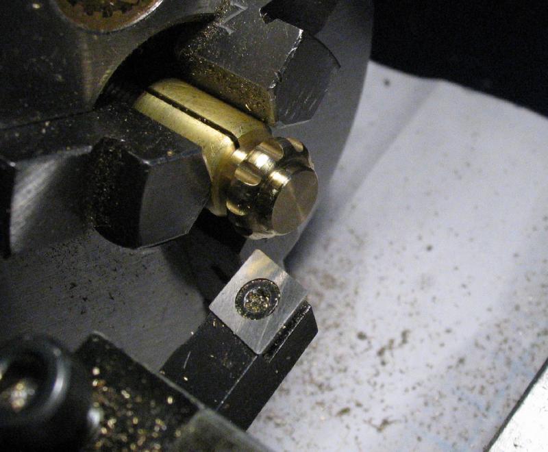
I wanted to replicate the traditional rope knurls that are found on Vibroplex keys, and Mr. Smith demonstrates his method of producing rope knurls using a custom-made knurling tool. He provides the name of the manufacturer (Accu-Trak), however, he does not give any dimensional information for the knurl wheel, such as the pitch and angle of the knurl, diameter of the wheel, etc. I made an attempt at producing a rope knurl wheel, following the methods that can be found on several other websites, but my setup for milling the angled grooves of the knurl was not rigid enough and failed at that stage. Since I was eager to produce a set of screws, I decided to use my usual knurling compromise and mill grooves instead. However, I used the same profile for the grip portion of the thumb screw that would have otherwise been knurled and is turned using a form tool, which I did have some success in making. This tool was started from a short piece of 3/8" square, oil-hardening tool steel bar. A smaller width of steel could have been used, but I was guessing at the correct dimensions when setting out. The top faces of the stock (I made both ends usable) were smoothed on an India stone and the bar mounted in the machine vise on the vertical slide. The slide was secured on the adjustable cross slide mount and set over about 10 degrees using a toolmakers protractor. The end faces were milled flat, and this was followed by milling a center channel with a ball end mill. The machined surfaces were smoothed on a stone prior to hardening in oil. It appears that there was a little warping during the hardening process, which was visible when the cutting edges were stoned, but this was not a problem. The radius was stoned with a round degussit stone that happens to be a very convenient diameter, but something a little coarser would have helped.
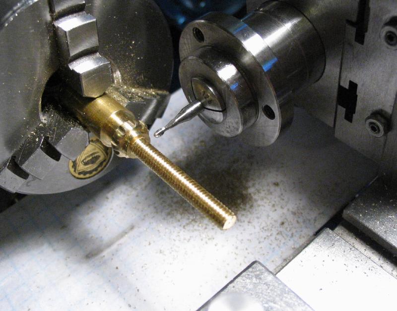
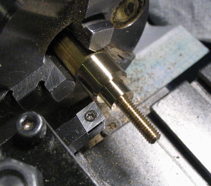
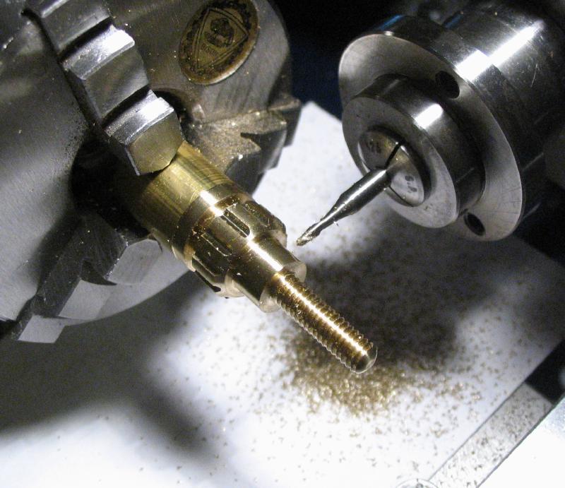
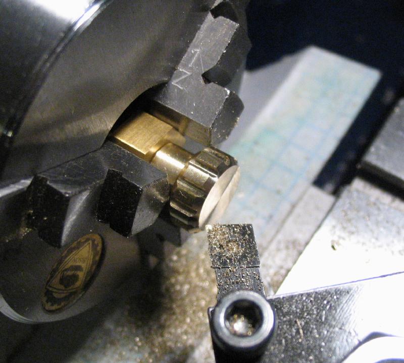
A parting tool was used to remove the bulk of the material and the form tool used to turn the radiused hub. A 1/16" ball end mill was used to give the hub ten grooves, indexing them with the headstock locking pin.
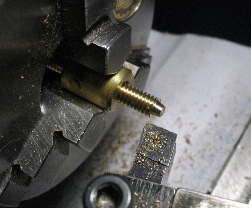
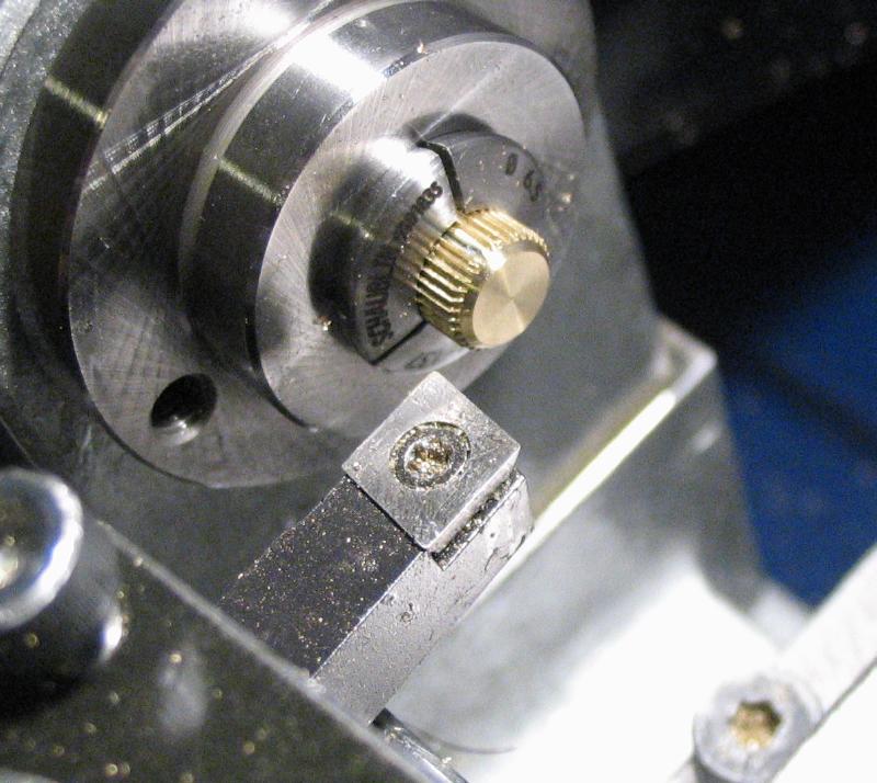
The thumb screw was parted off, and the screw head faced with the screw mounted in the brass clamp made above. The tip of the first screw was turned to a short taper with a small diameter flat face. This one will be the stop screw for the pendulum bar.
A second screw is made that is turned with a small shoulder to fit the small coil of the pendulum bar return spring.
Two more screws are needed; both are contact screws. Normally there would only be one, but the second is replacing the right-side pendulum bar stop screw. Both these screws are faced, center drilled and drilled to fit the silver contact inserts that will be made below. The end was chamfered to clean things up.
The silver inserts for the two contact screws were made from sterling silver wire in a similar manner as above for the contact plates. However, they are not riveted in place, but are simply a friction fit in the hole drilled in the end of the screw. Silver wire was held in a collet and a short length turned down to fit the screw and then parted off. The parted side was faced and rounded over with a graver.
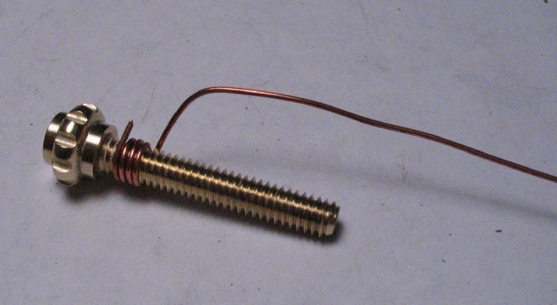
The screws must be plated prior to installing the silver contacts. The screw was attached to copper wire by lightly threading the wire around the screw. As the plating is taking place, the wire can be 'screwed' along the length of the screw in short increments every few minutes so that the full length is plated.
The locking thumb nuts are made from brass rod, but it is too large to pass into the headstock. Two were made at the same time, to reduce waste as best as possible. A total of five are needed, but I made the first nut following the method in the book (not shown below), and this method is suited to batch production but not for a small lathe. The fifth nut lacks the small diameter shoulder and will be used to lock the upper pivot screw. As with the thumb screws above, the shoulders were turned with a right hand tool bit and the parting tool used to remove most of the stock before finishing the radius with the form tool.
The rod was drilled and tapped to fit the set screws above. The length of the stub drill and tap are just long enough to thread two nuts at the same time. The rod was extended from the chuck and the profile of the second nut turned in the same manner. The milling spindle was installed and twelve grooves milled into the hubs of both nuts at the same time. The nuts are then parted off. Not shown, but the shoulder on the second nut needs to be turned prior to parting it off as well.
Upon examining the assembled screw and lock nut on the post, I decided the nuts would be more functional if made thinner. Mr. Smith doesn't give exact specifications for various widths, e.g. the shoulders either side of the rounded grip. I guess-timated 1/16", but this can be cut in half. Since all the nuts were already made, I reduced them using a step collet to face down the screw-head side and a regular collet to hold the small diameter on the post side.
Posts are matched up with each of the screws and a lock nut. There was not much to photograph although there was a lot of trial and error in carrying out this step. Each of the posts must be reduced by facing the threaded end to its final height. This is found by matching the assembled screw and post and trying it against its contact point on the key. The return spring screw was used for each post since it has a point, which makes it easier to see its location. The two contact screw posts will have an insulating bushing that raises the height 1/16", so this has to be accounted for as well and a piece of 1/16" brass plate was used as a temporary approximation. Some of the screws are much longer than need be, so I will need to reduce them later. The screws should be at about half their thread length when initially set up, so that there is plenty of adjustment available in use. The paddle and pendulum bar assembly needs to be at its desired height when finalizing the post heights and should also be set up perpendicular to the bridge (the upper pivot screw was tightened up to keep this steady). The location for the posts are a little tricky to determine accurately, but a combination of guides were drawn on the plate with a fine tip Sharpie pen and a location finally settled on and center punched. A couple important points to keep in mind is that the mainplate will be reduced in width later, so the posts must be within this width. Likewise, the mainplate will fit within a base and screws/posts must clear this as well. This results in much less freedom of placement than might be assumed at first. In fact, I discovered that the dash contact will need to be remade a little longer since its post cannot reside at that location. Looking at the last photo in Mr. Smith's book, which shows the left side of one of his finished keys, it appears he experienced the same problem, as the contact is moved up and has its own screw instead using the paddle bar return spring screw. It also appears a second hole was drilled for the dot return spring, for likely the same reason. The dimensions given leave about 2mm or so of clearance.
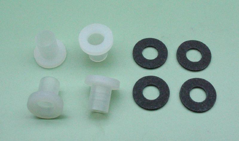
The plate is moved to the drill press and the locations drilled through. For the stop screw and return spring posts, the hole is to clear the threads of the fillister head screws but the contact screw posts are drilled to pass the plastic insulator sleeves. A fiber washer is used in place of a brass washer on these insulated posts as well.
With the screw post locations settled on, I riveted the pendulum spring into place in the pendulum bar and the weight rod. A small flat stump was installed in the staking tool and the stake made above for riveting the silver contacts was used here as well.
Damper
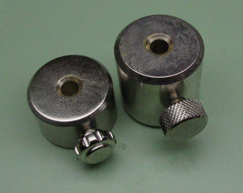
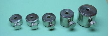
The damper is simply a brass washer that hangs from a post and absorbs any vibration in the pendulum when the key is at rest or while making dashes. It was made from brass rod; the weights for the pendulum are the same diameter, so I started with a length for making the damper as well as a couple different weights.
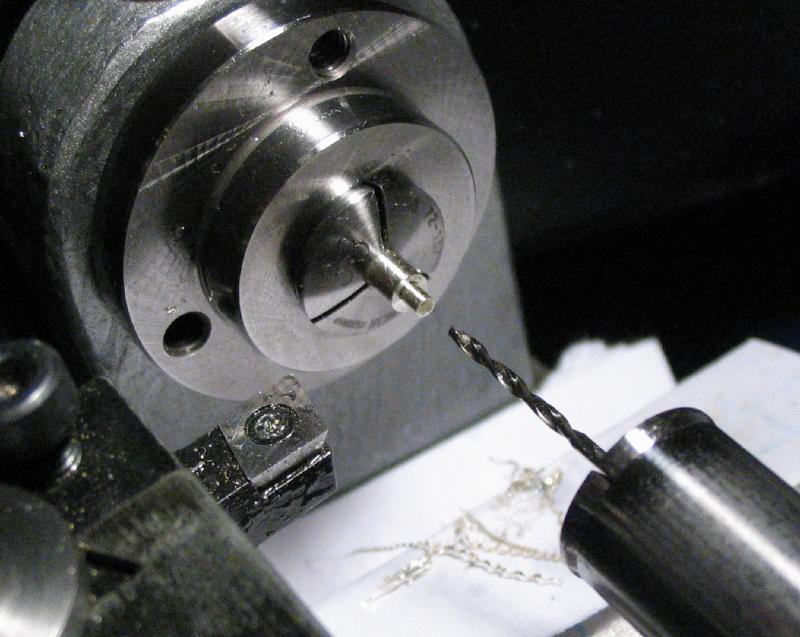
One end was faced and a section sawed off on the power hacksaw. The piece for the damper was held in a six jaw bezel chuck to face the sawed side and bring it to its correct thickness. It was spot drilled and drilled to a generous clearance with its mounting screw. The hole and corners were chamfered for a nice finish.
One end was faced and a section sawed off on the power hacksaw. The piece for the damper was held in a six jaw bezel chuck to face the sawed side and bring it to its correct thickness. It was spot drilled and drilled to a generous clearance with its mounting screw. The hole and corners were chamfered for a nice finish.
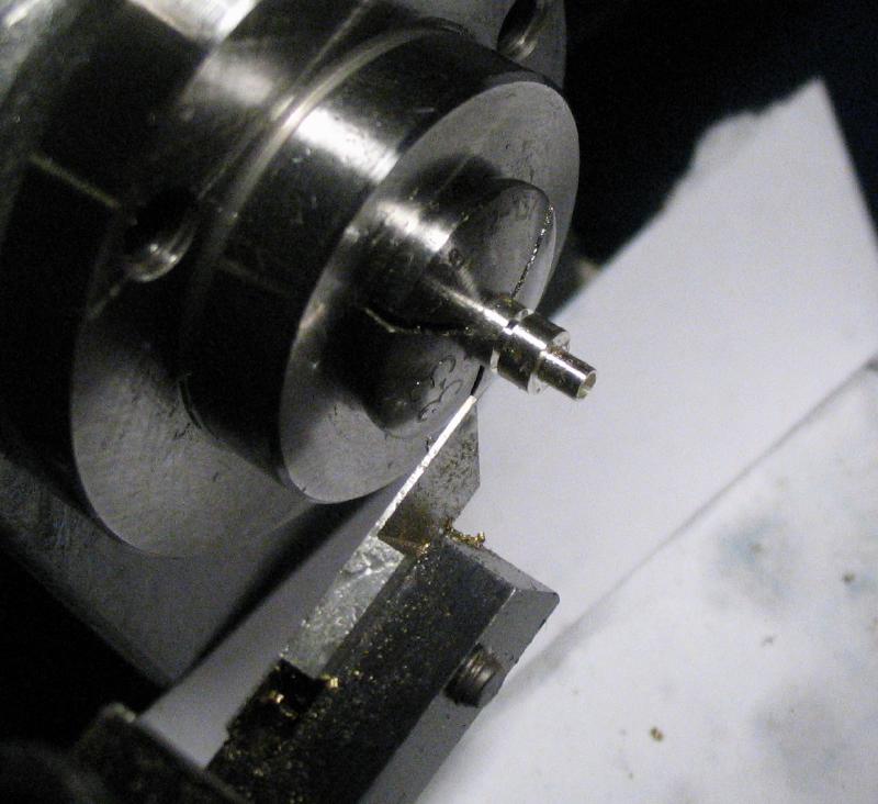
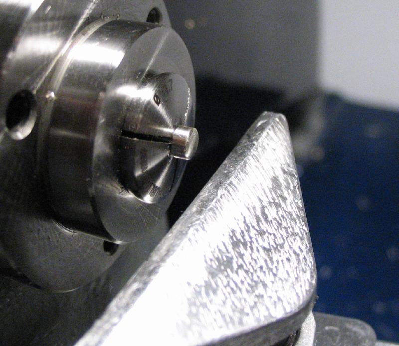
The post for the damper was made from brass rod, which is drilled, tapped, polished, and parted off slightly over size. The post is then brought to final length while facing the parted side.
The damper was attached to the post with a temporary screw and washer and pushed off center to be at the position it will assume when hanging under gravity. The widest radius is the bottom of the damper and will hang towards the bridge. A transfer screw was inserted into the end of the post and the position for the post found on the mainplate. I considered making an adjustable damper of some sort since this damper is not, but this version is quite simple to make. Since the location is permanent, it must be located carefully, with the side of the damper touching the end of the weight rod with the key centered. I used a piece of Rodico putty to help hold things steady while I inspected. The post was held firmly and the screw head hit with a mallet to mark the mainplate with the transfer screw point. The hardware for the completed damper include a long round headed screw, which was deplated, polished and blued, and a stock brass hex nut to lock the screw on the back of the plate. The brass components were nickel plated.
Pendulum weights
I am starting with a 3/4" and 1/2" thick weights from 3/4" brass rod. Various size weights can be made and their weight combined with their location on the pendulum weight rod will result differing dot rates. So some experimentation will be needed. I will need to slow it down to start out learning to use it, so I decided on some larger sized weights to begin with. The weights were drilled and reamed to fit the pendulum weight rod and chamfered at the corners and holes.
The weights need to be cross drilled and tapped for a fixing screw. They were drilled on the lathe and then setup for tapping at the drill press. I am using a stock, knurled brass thumb screw, and I also made one that matches the various other thumb screws and nuts of the key. Since they are ready to use, I nickel plated them.
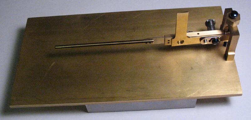
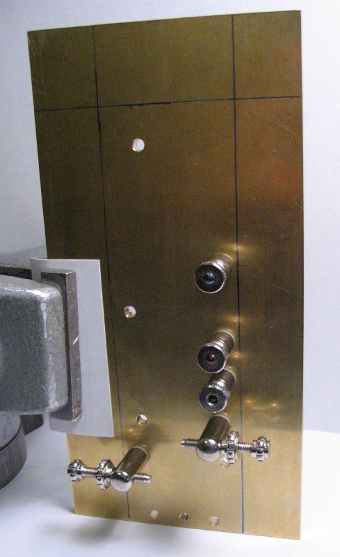
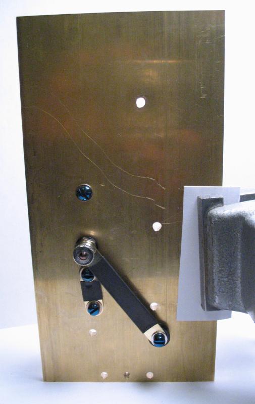
The mechanical components of the speed key are essentially complete at this point, so it was assembled and held upright with the aid of a small vice. I started nickle plating many of the components that I believe to be complete. I have not previously adjusted a speed key before, but the current setup seems to function as it should, generally speaking. The left set screw is positioned so that the weight rod is just touching the damper, and the right side set screw (and alternative dot keyer contact) is set far enough away to provide sufficient energy for the vibration of the pendulum when moving the paddle/pendulum assembly to the right. For setting up bugs, online recommendations seem to vary quite a bit, but I decided on 0.015" to start and this appears to provide vibration. A 0.015" feeler gauge was used to set the contact gap.
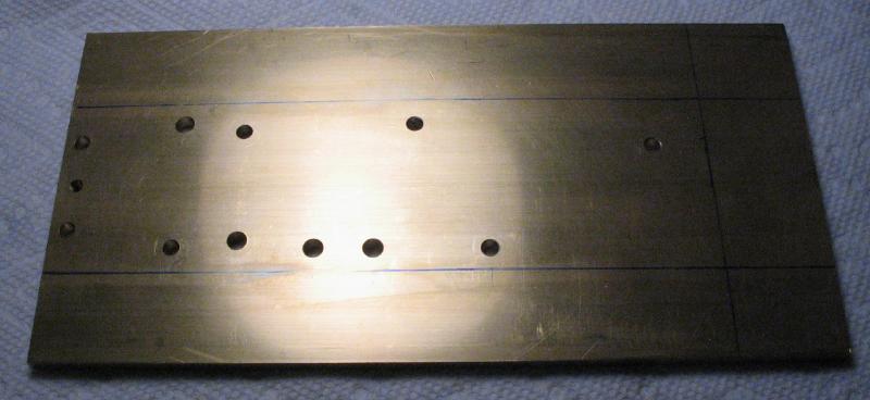
The plate was approximately marked off where it will be cut away later, but these lines will help in laying out the final components of the key, all of which will attach directly to the plate.
Magnet - Reed Switch
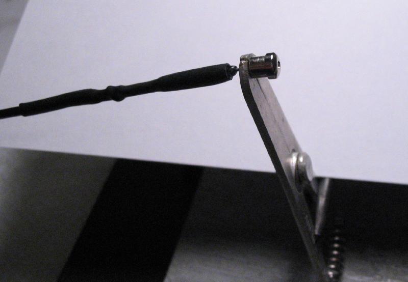
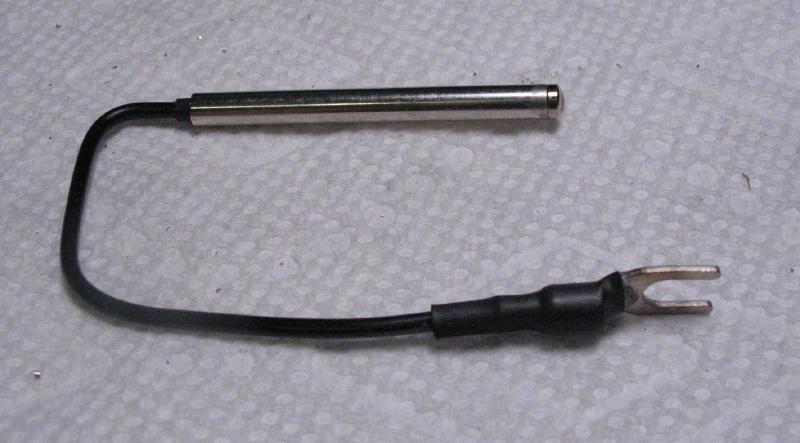
The reed switch I used is pictured below and purchased on Ebay as a packet of 10 for about $1. Although not marked, the auction was for a model # MKA-14103 (2mm x 14mm). It was chosen for its size, since it will need to fit into a brass tube. It consists essentially of two metal contacts sealed in glass. When under a magnetic field, the switch closes. One lead of the switch was wrapped around the end of a length of 18 AWG wire and soldered in place. The connection and most of the switch were sealed in heat-shrink insulation tubing.
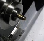
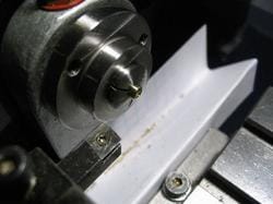
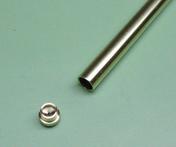
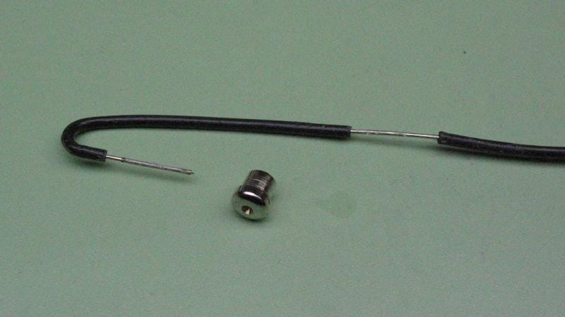
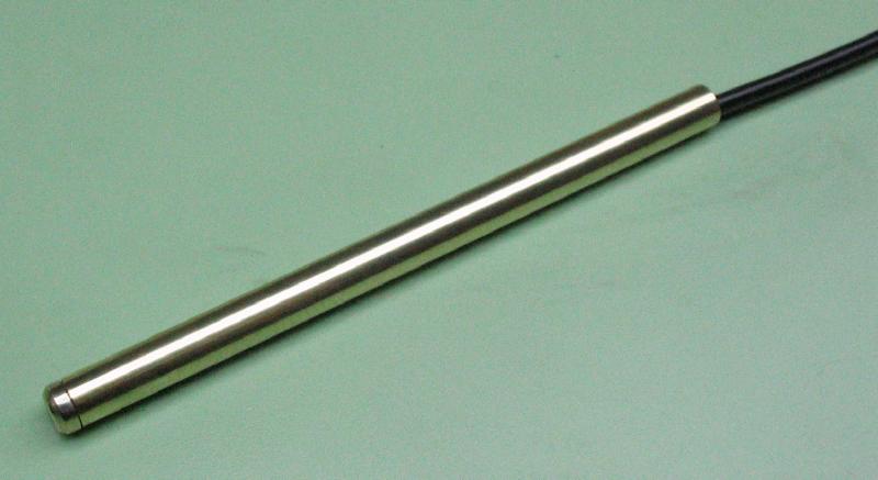
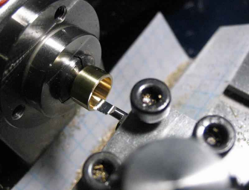
The reed switch fits into a length of brass tubing (K&S Precision Metals). An end cap needs to be made that fits in the end of the tubing and is soldered to the other lead of the reed switch. The end cap was made from a short piece of brass rod, turned to a snug fit in the tubing and drilled to pass the lead of the switch. It was parted off and the reverse side rounded over. The hole was countersunk as well to provide plenty of space for solder. Prior to soldering, the end cap was nickel plated. A length of insulated wire was modified to hold the end cap while plating. The free lead of the switch was cut fairly short and inserted into the hole in the end cap and soldered into place. A small aluminum clamp was used to help position the work for soldering. The tube can be installed from the other end and secured onto the end cap.
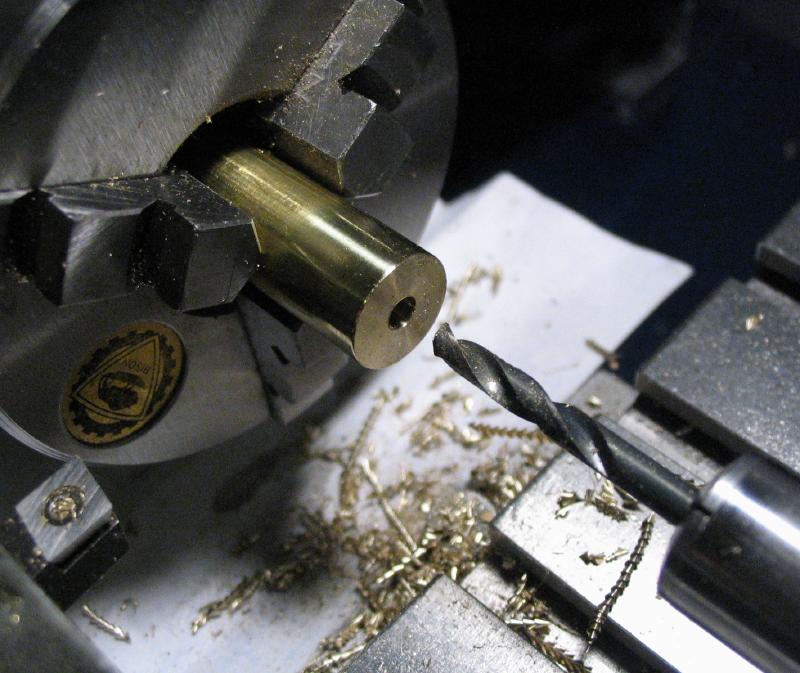
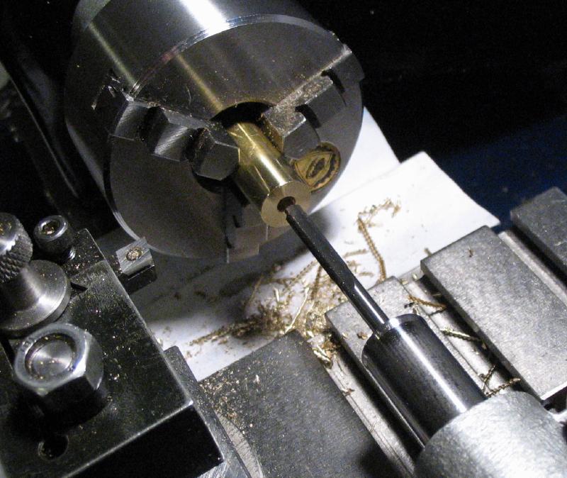
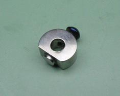
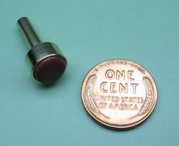
The collet for the magnet was made from brass rod. The rod is drilled and reamed to fit the pendulum weight rod and then transferred to the machine vise on the vertical slide where a flat is milled on one side. The reverse side of the rod is drilled to be tapped. It is parted off and then set up for tapping.
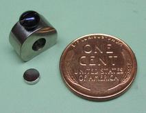
The collet needs to be nickel plated before permanently attaching the magnet. A small zinc-plated steel screw was deplated, shortened, polished, and blued. The neodymium ("rare earth"), mini-size disc magnet was available in nickel plate as well (from McMaster-Carr). It was attached to the collet with a small dab of super glue (non-magnetic brass tweezers are helpful for positioning it into place).
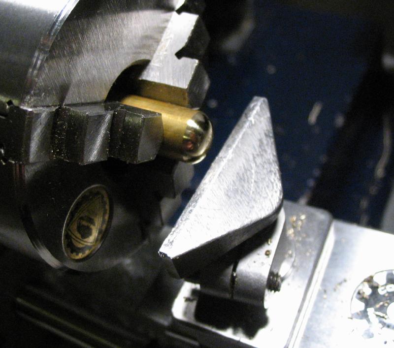
The post for the reed switch tube was made from brass rod. The top was rounded over with a handheld graver on the lathe T-rest and then spot drilled, drilled and tapped for a set-screw.
The post was moved to a vise and cross drilled and reamed to fit the switch tube.
The post was then brought closer to its final length by measuring and parting off (I started with a left-over length of brass from making one of the thumb screws). The base of the post was then spot drilled, drilled, and tapped.
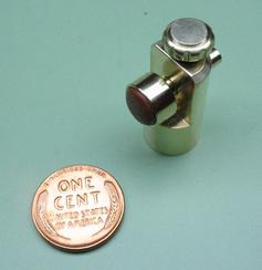
The magnet and its collet are mounted on the weight rod at a set distance from the end of the riveted end and the magnet face is in the same plane as the mainplate. A piece of brass rod the same diameter as the switch tube is inserted into the post and the assembly placed on the mainplate so that the brass rod is perpendicular to the weight rod and underneath the magnet (if it fits). The post is then shortened so that the gap between the rod and magnet is at a specified width. Feeler gauges were used to check the progress, however, being made of steel they tend to stick to the magnet.
Terminal Posts
The terminal posts are the connection point for attaching the wiring that goes to the transceiver or electronic keyer, etc. The posts are fairly simple, and were made from the short pieces of brass rod left over from making other parts above. Two posts are needed for the speed key and a third is needed for the optional dot contact for electronic keyer use. One is made about 1/16" longer than the other two that mount on top insulating sleeves. The rod is faced, drilled and tapped. The length needed is scribed on the rod, parted off, and the parted face turned true. The surface was polished by mounting on the screw-and-nut arbor described above.
I deviated from Mr. Smith's book with the dash terminal post. Since the reed switch connects to this post on the back and needs to be disconnected for keyer use, I wanted to use binding nuts on both sides for tool-free change over from speed key to paddle keyer. I also wanted to provide an increased height for the conductor bar that will be made later and place it above the other screw heads. This meant making a pair of washers from Delrin rod and a brass nut from hex rod.
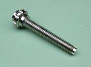
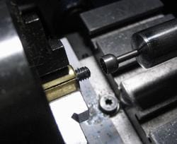
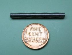
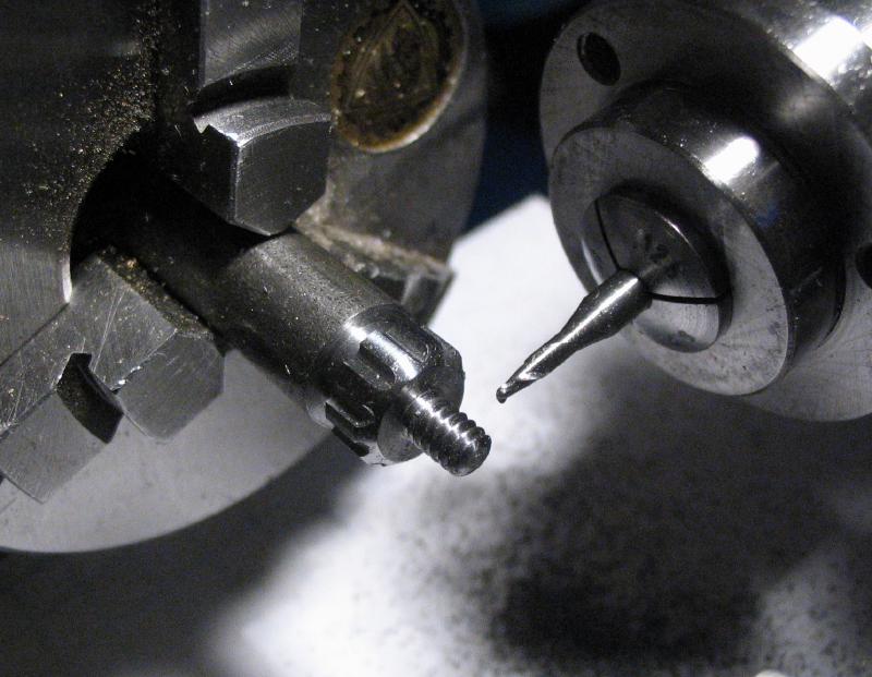
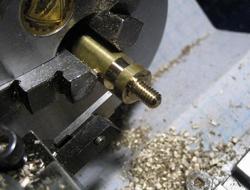
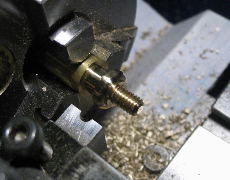
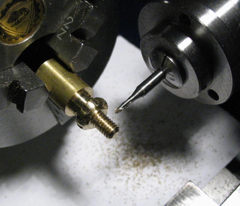
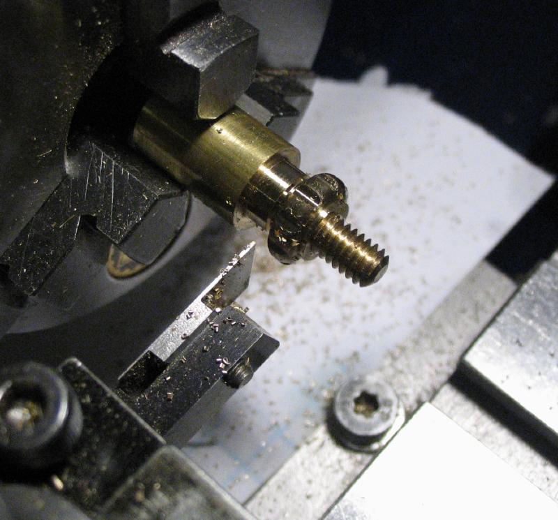
A length of threaded rod is needed in place of a screw for the dash terminal post. This was made from 12L14 cold roll steel rod. One end was turned to a 60 degree point and then supported with a short piece of drill rod held in a collet in the tailstock that was previously center drilled (I currently lack a proper female cone center). The rod was turned and threaded with a die and the required length of thread parted off. The ends of the threaded rod were faced and rounded over with a cup bur while held in the screw clamp made previously. Once complete, it was blued in the same manner as the screws.
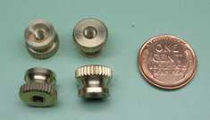
The remainder of the hardware is stock. The binding nuts are brass thumb nuts, round head screws were cut to the required length (my longest screws on hand in this thread) and deplated, polished and blued as with other screws, and washers and plastic insulating sleeves added to the terminals for the contacts.
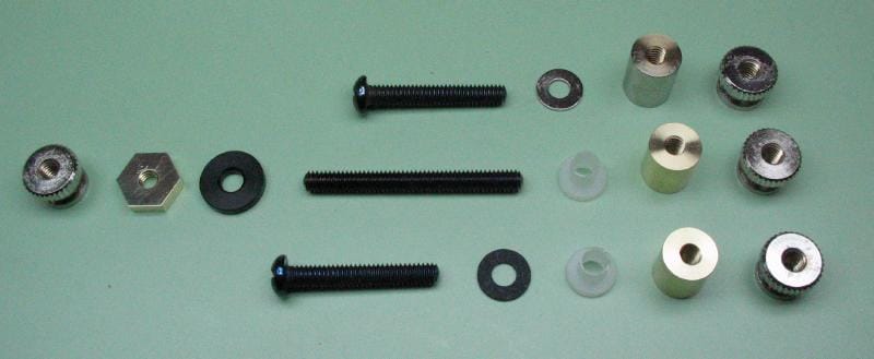
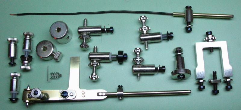
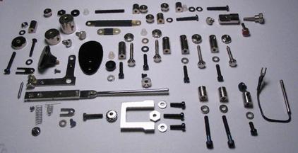
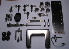
The positions for the terminal posts were laid out on the mainplate and drilled to pass their screw and/or insulating sleeves. While the key was disassembled, I took a photo that shows the various components made thus far.
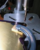
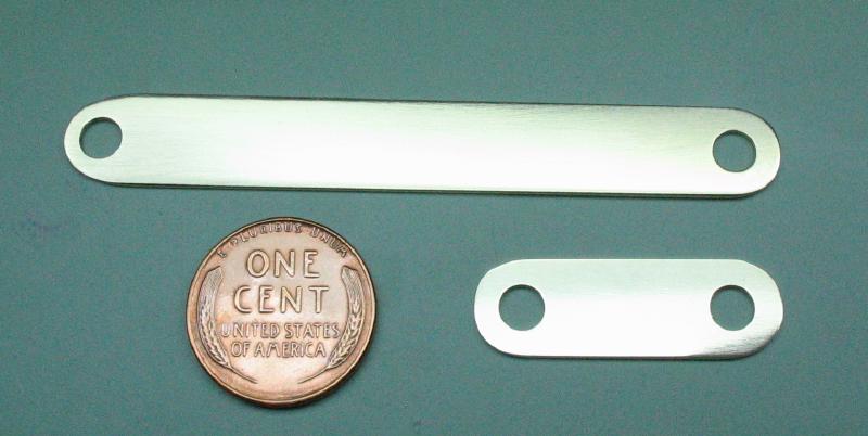
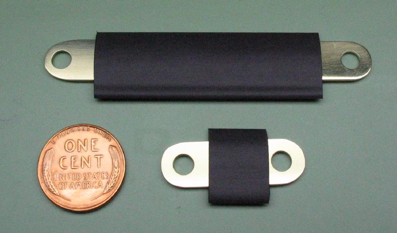
The two insulated terminals need to be connected to their respective contact posts using bus bars, which were made from brass sheet (the brass was labeled as #253 brass, but choices were limited in this thickness). The distances between screw hole positions were measured on the mainplate and then scribed onto the brass sheet, and the general outline of the bar scribed as well. The shape was primarily cut out using the Cowells table saw attachment, and the ends rounded with a jewelers' saw followed with filing. The holes were drilled through, and the work then polished with emery paper. It is easier to drill the holes before cutting out since the large sheet is easier to clamp securely, this can be seen while making the second one.
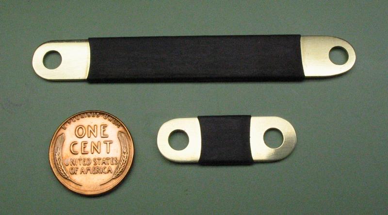
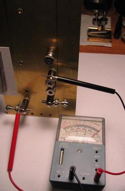
To prevent accidental shorting during use, the bus bar was wrapped in heat shrink tubing. The terminals and respective contact posts were installed with bus bars in place and the conductivity of the various parts tested with an Ohm meter to be sure everything is properly insulated or connected as intended.
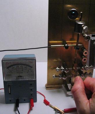
The key was reassembled for additional testing and to help finalize the finished dimensions of the reed switch assembly. An Ohm meter was connected between the common terminal and the loose wire end of the reed switch. The tube is positioned so that the reed switch is under the pendulum-mounted magnet such that the circuit is open when the key is at rest and oscillating between open and closed when the pendulum is set vibrating with a push of the paddle bar to the right. The rapid opening and closing of the circuit appears as a vibrating needle point on my analog Ohm meter. The reed switch position is then fine tuned so that the needle hovers at about mid-scale, which should approximate equal on and off periods.
The reed switch tube was shortened to its final length and nickel plated. The wire was shortened to its final length and a spade connector attached and soldered into place. The joint was also sealed in heat-shrink tubing, The position of the reed switch will need to be adjusted when making changes to speed or screw stop, so a thumb screw was made from 12L14 mild steel rod and blued to replace the stock slotted screw.
Pendulum Stop
The key can be currently used to trigger an electronic keyer if wired correctly to all three terminals and the reed switch unconnected. To prevent the pendulum from vibrating while using the key for this purpose, an adjustable stop was made. The post for the stop was made from about one inch of 1/2" brass rod. It was faced, drilled and tapped for an 8-32 screw. The reverse face was trued and chamfered 45 degrees. The rod was coated in layout blue and the pendulum rod height scribed onto the brass rod. This position was cross drilled 1/8" and then reamed 5/32".
Space on the mainplate is somewhat limited, so the post was milled to provide a recess for the stop piece. The position for a locking screw was drilled and tapped as well.
A thumb screw was made in a similar manner to the set screws made earlier. A length of brass rod was turned and threaded, and the screw head roughed out with a parting tool. The shape of the screw head was shaped with the special form tool made previously, and then grooved with the milling spindle and a 1/16" ball end mill. Finally, the screw was parted off.
Since the stop piece will prevent easy changing of the weights, I decided to add a thumb screw for fixing the post to the mainplate. This way it can be removed or attached relatively easily without the need of a screwdriver.
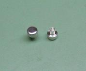
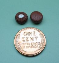
The stop piece was made from brass rod and turned to fit the reamed hole in the post above, using the traveling steady. The work was polished while mounted on the lathe, and then parted off, leaving about 5mm of length at full diameter. The work was reversed into a collet and the parted end faced and bored open to accommodate a small pad that will stop or fix the weight rod. I pondered on what may be the best choice of material to use for the pad, but came upon the following option purely by happenstance. I know nothing of saxophone construction, or playing for that matter, but the key holes are sealed with a special type of pad (shown below) that appeared to fit the bill for this application. These pads are available in a variety of different diameters to match the various saxophone keys, which provides a convenient selection of sizes to choose from. The examples shown are 8mm in diameter and made by Prestini. Once the stop piece was plated, the pad was permanently fixed into place. I read that shellac is the preferred adhesive for attaching the pads in instruments, but I substituted with rubber cement.
The Base
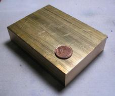
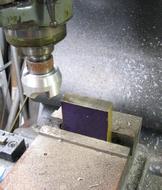
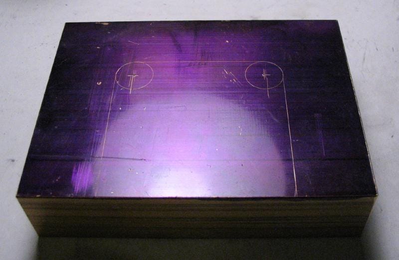
The base starts with a block of brass. Mr. Smith demonstrates cutting out the raw material from what must have been a fairly hefty piece of brass plate, however, I tried to minimize the cost and purchased a piece of brass bar of the required thickness and width and about 0.25" excess in length. As noted above, many metal suppliers offer cut-to-length service, which is very helpful in this case. I think this is the single, most expensive component of the whole key. It was received with roughly sawed ends, so first, the sawed edges were milled to be square with the extruded stock faces. This was done on a Bridgeport milling machine with a large facing mill. The faces were used as a reference for laying out the dimensions of the center portion that needs to be removed. I purchased the stock oversized by a 0.25", but even after squaring up, it still measured 0.25" wider than suggested, but rather than mill this off as waste, I decided the key's base will just be a little larger and the added weight may be helpful in keeping the finished key from scooting around the desk top during use.
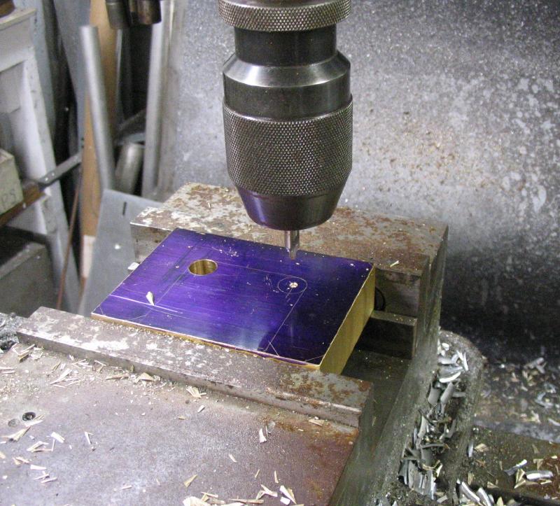
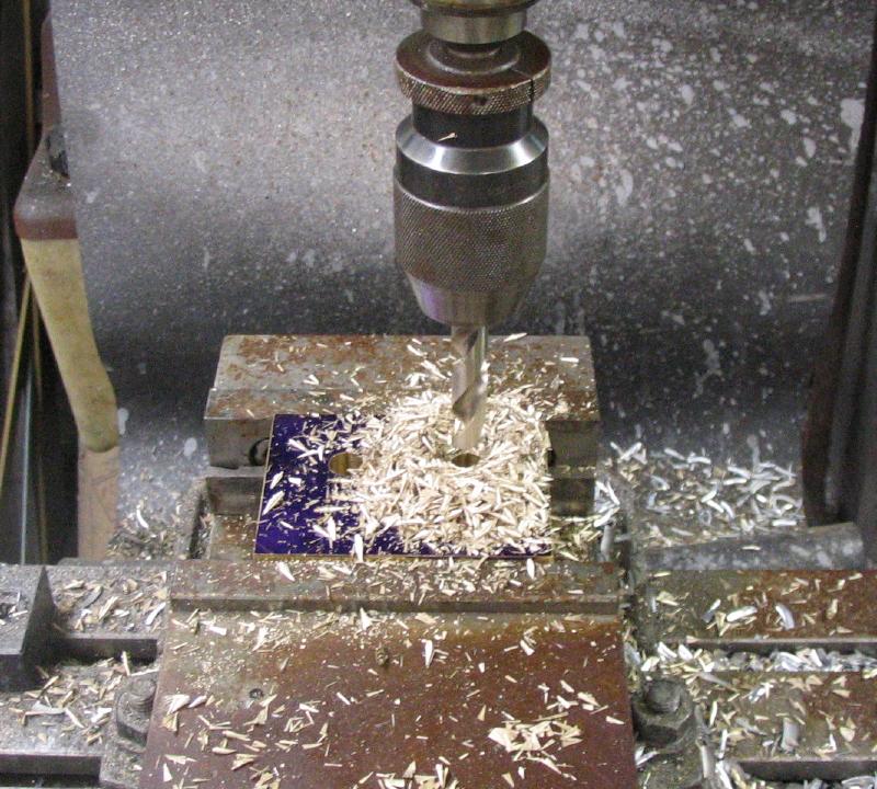
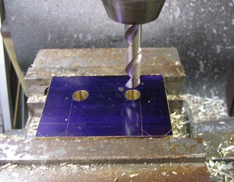
The holes that form the inner corners of the recess for the mainplate are center-punched and the locations found on the milling machine, center-drilled, and then drilled through.
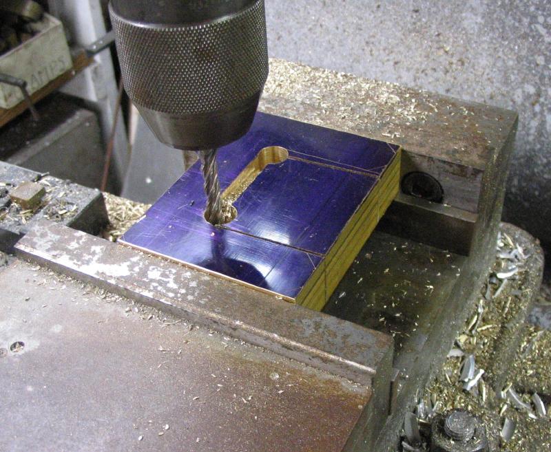
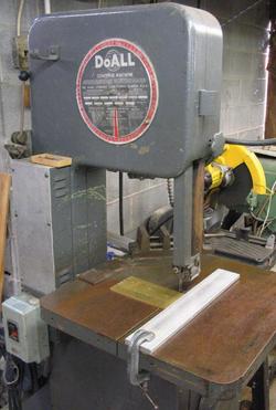
To make a start at removing the center portion, the block was first sawed on either side using a band saw, although I did have some trouble sawing along the scribed line, but this can be corrected on the mill. The center portion was finally removed by milling a channel along the rear scribed line and through the base and connected with the sawed cuts. The internal faces of the base were then squared up using the side a 1/2" endmill.
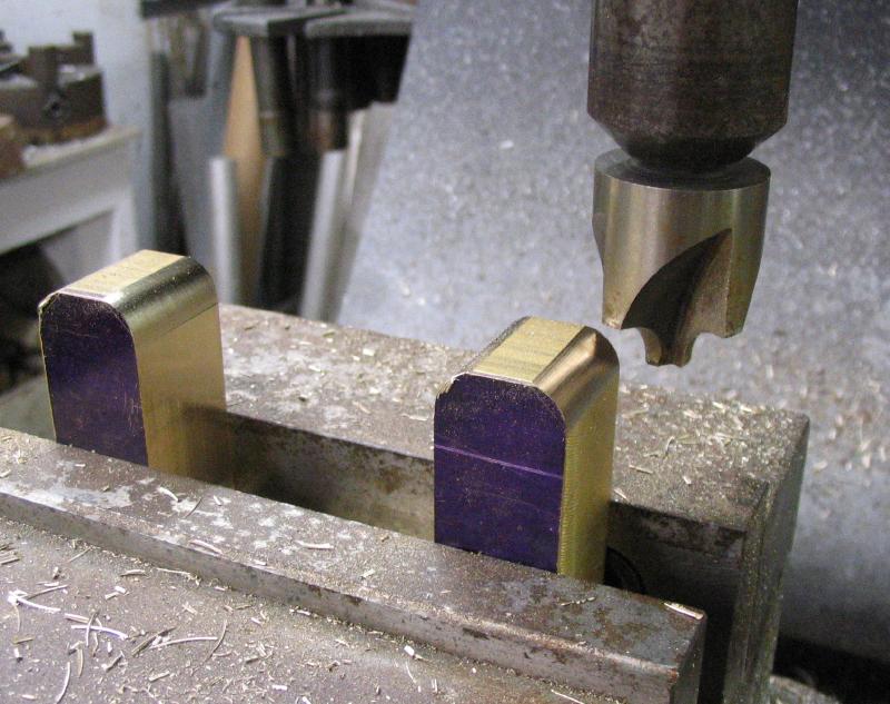
The front edges were rounded over with a 5/16" radius endmill and the remaining top edges and rear corners (not shown) rounded over with a 3/16" radius endmill. This provides a convenient starting point for the remaining steps of forming the shape of the base, which will need to be done by hand methods.
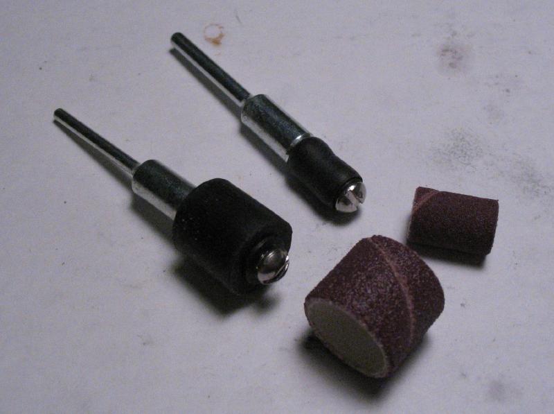
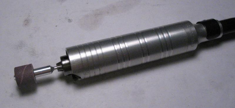
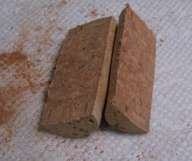
The base was then brought to its final shape with files and sanding. The sanding bands are made by 3M and are available in 80 to 320 grit , they fit onto an expanding rubber arbor that can be used in a hand held rotary tool, such as the Foredom tool shown. This was followed by polishing with emery paper wrapped onto a piece of cork. A convenient shape can be made from a bottle cork cut roughly in half lengthwise.
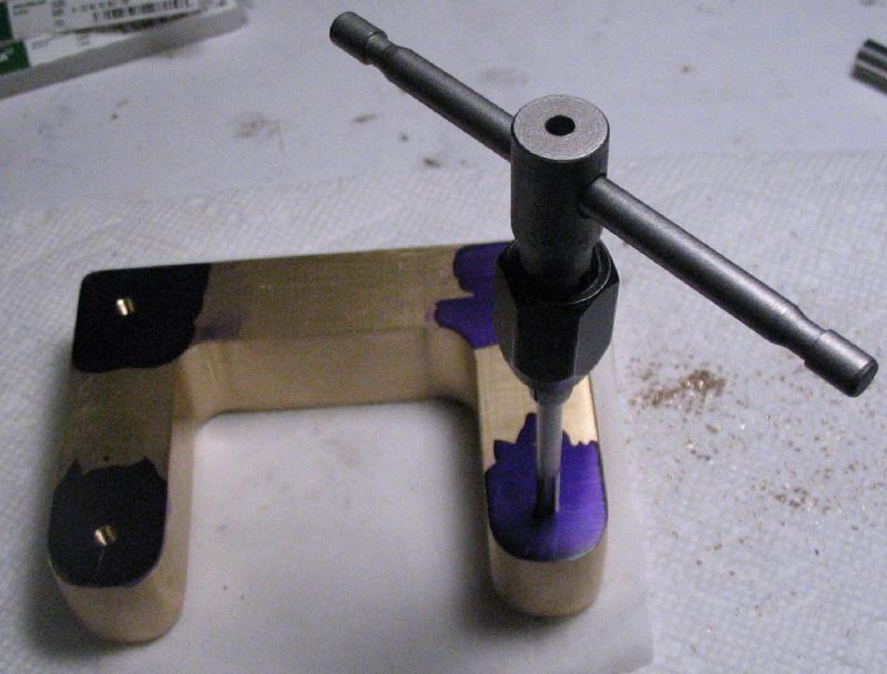
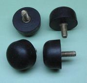
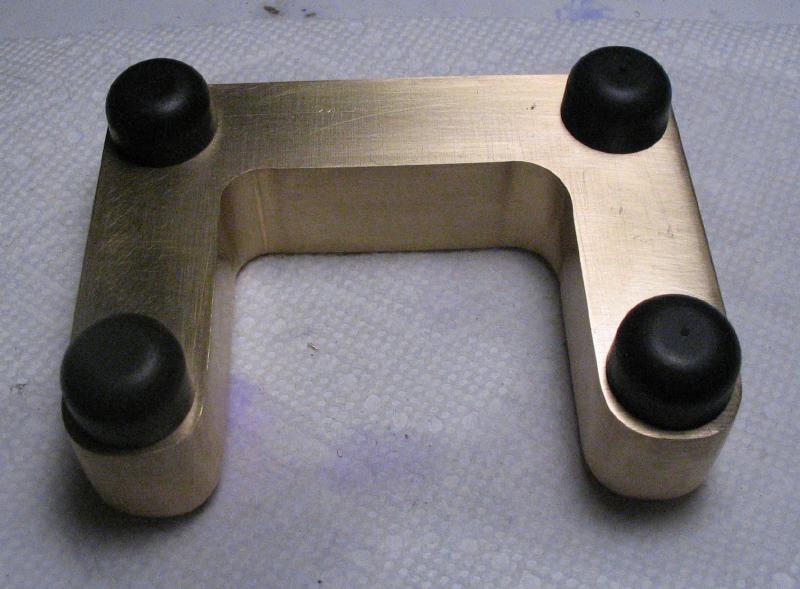
There are a few more machining steps to preform before getting too far along with polishing the base. Rubber feet with threaded studs were purchased from McMaster-Carr. The positions for the feet were scribed on the bottom of the base and center punched. The punched locations then drilled and tapped to match the threaded studs.
The mainplate was reduced on a bandsaw to remove the excess length and width, although my ability to cut a straight line has apparently not improved. The edges of plate were made closer to square and to final size by facing with an endmill on the milling machine.
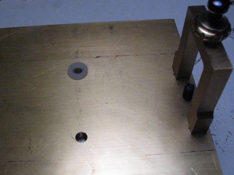
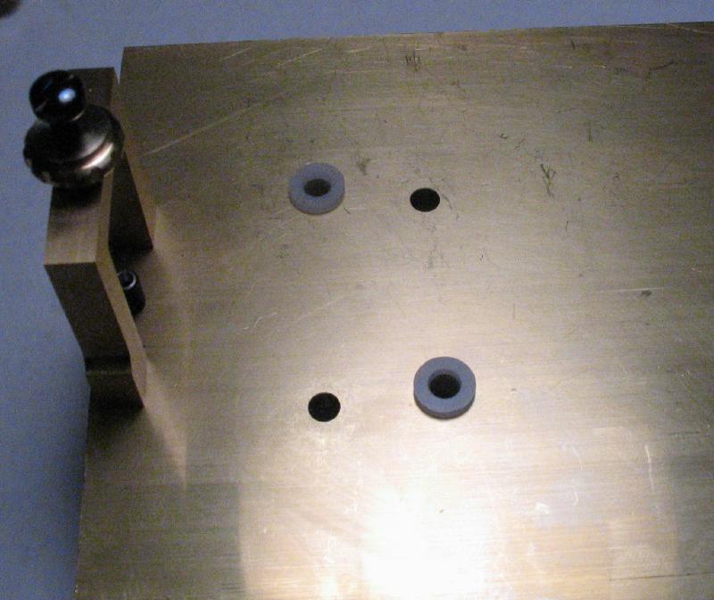
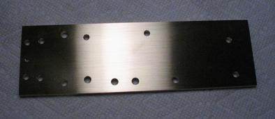
The positions for the mounting bolts were laid out on the mainplate and drilled with a clearance drill. The plate was also given a quick scrub with 400 grit emery paper to clean up the surface and remove most of the scratches. The intended mounting height was scribed on the base and the mainplate aligned to mark the bolt positions through the drilled holes of the plate. The positions were center punched and then drilled and tapped for the mounting bolts.
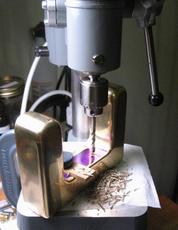
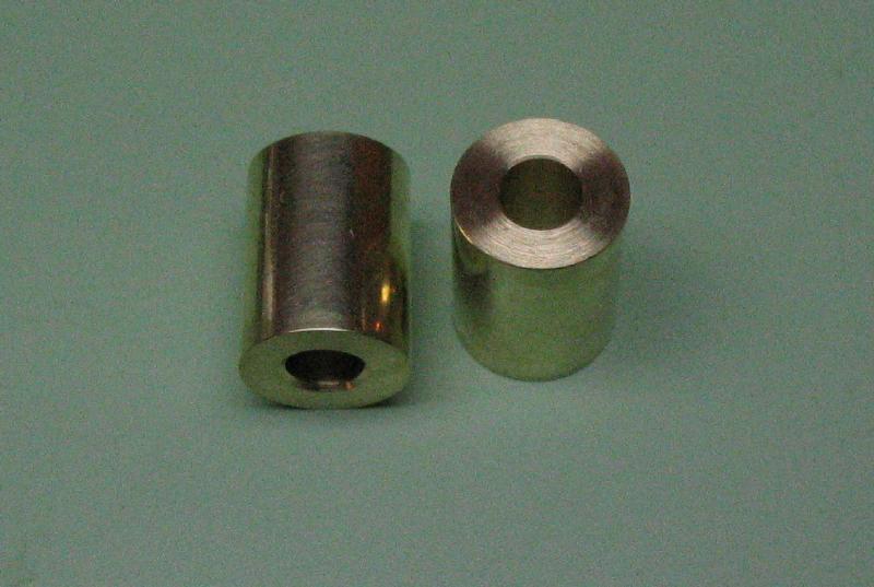
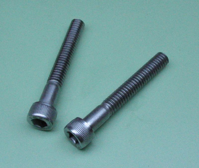
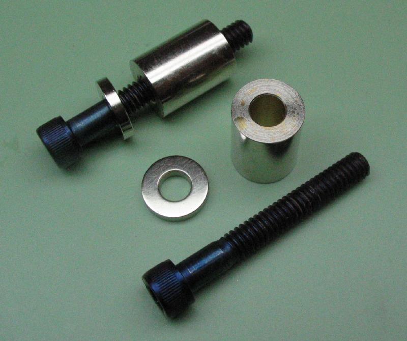
A pair of stand-offs are used between the mainplate and the base. They were made from left-over pieces of brass rod that were faced, parted or faced on the reverse end to bring to length, and drilled through with a clearance drill. The holes were countersunk with a jewelers bur. The mounting screws are a socket head type of screw and were purchased in zinc-plated steel. As with other screws, they were deplated in acid, the threaded end rounded over with a cup bur and the head polished prior to heat bluing. I used Luxi gray-color compound on a fiber mop and using a Foredom flex shaft tool. I have been experimenting with various Luxi compounds while polishing many parts of this key, especially brass components. Luxi offers a mini assortment of their different compounds, which is convenient for trying each, and in some cases may be more than will ever be needed.
A trial fit of the mainplate to the base with its hardware was made to be sure everything fits, is aligned, and secure.
Dash Knob / Finger Piece
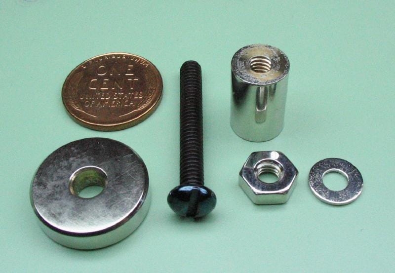
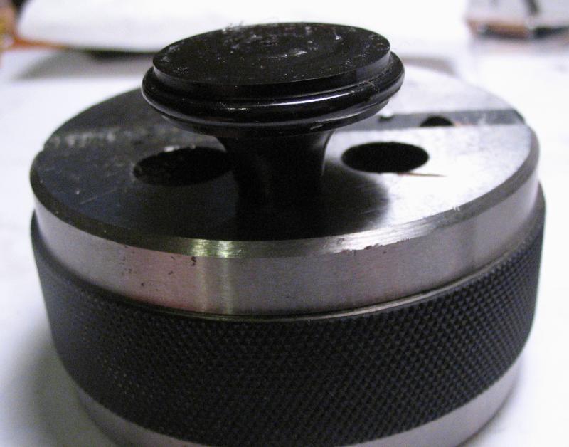
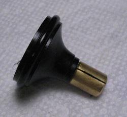
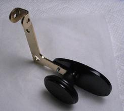
Mr. Smith recommends purchasing a dash/finger knob, and therefore does not provide the dimensions or construction details for making one. I decided to make one since almost every other component of the key is home made as well. First, the screw insert was made. A short piece of 1/4" brass rod was turned down to be threaded #8-32 and a waist just over 1/16" in length was formed to provide some freedom when it is mounted through the paddle-knob bar.
The insert was transferred to the dividing head, which was mounted on the cross slide with its spindle at lathe center height. A 60 degree point mill-drill was used to mill splines into the insert, and the dividing head used to index through 36 positions. The insert was moved back to the lathe headstock and parted off. The parted face was trued and the corners chamfered 45 degrees.
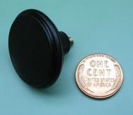
The knob itself was started from 1-1/4" diameter black Delrin rod. It was faced, turned down to about 30mm in diameter, and a boss turned that is about 3/8" in diameter. A 6mm hole was drilled and then lightly bored open to provide an interference fit with the screw insert above.
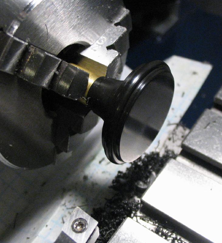
A parting tool was used to start forming the rim of the knob, but the stock length was slightly too short and the work needed to be moved to the 6-jaw chuck to provide additional space for the tool to fit. The form tool used above on the various thumb screws and nuts was used again here to round over the rim of the knob. A graver made from 1/8" drill rod was used to turn the curved shape, and the turned surfaces were then polished with Tri-M-ite paper. The knob was then parted off.
The screw insert was placed into a hole of the bench anvil and the knob tapped on with a mallet. The assembled work was mounted in the screw clamp made previously, and mounted back on the lathe to turn and polish the parted face of the knob.
Dot Paddle / Thumb Piece
The dot/thumb paddle is made from acrylic sheet. Mr. Smith demonstrates cutting out his monogram in the paddle using a jewelers saw. I sketched at least a dozen ideas for my own monogram that varied from tacky-looking to impossible to actually cut out, so a plain paddle was eventually decided on. The acrylic sheet was supplied with a protective paper covering, which is useful for laying out the work to be cut out.
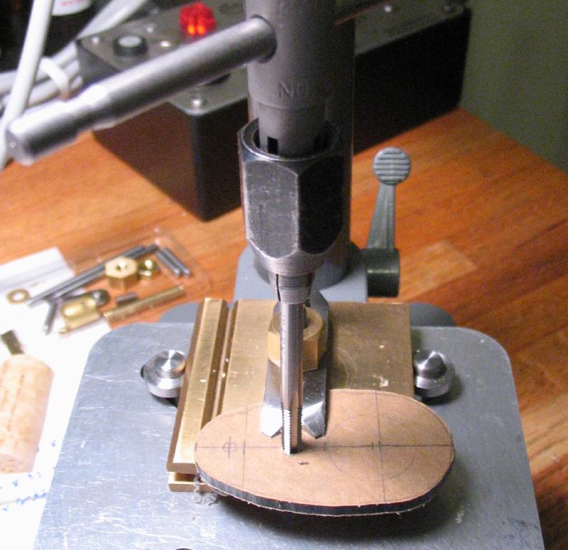
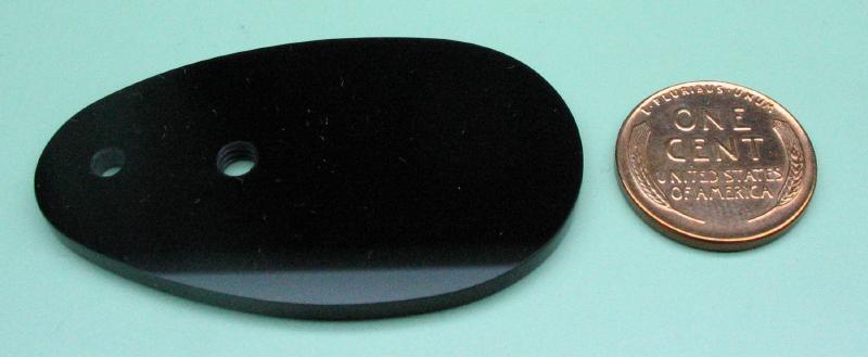
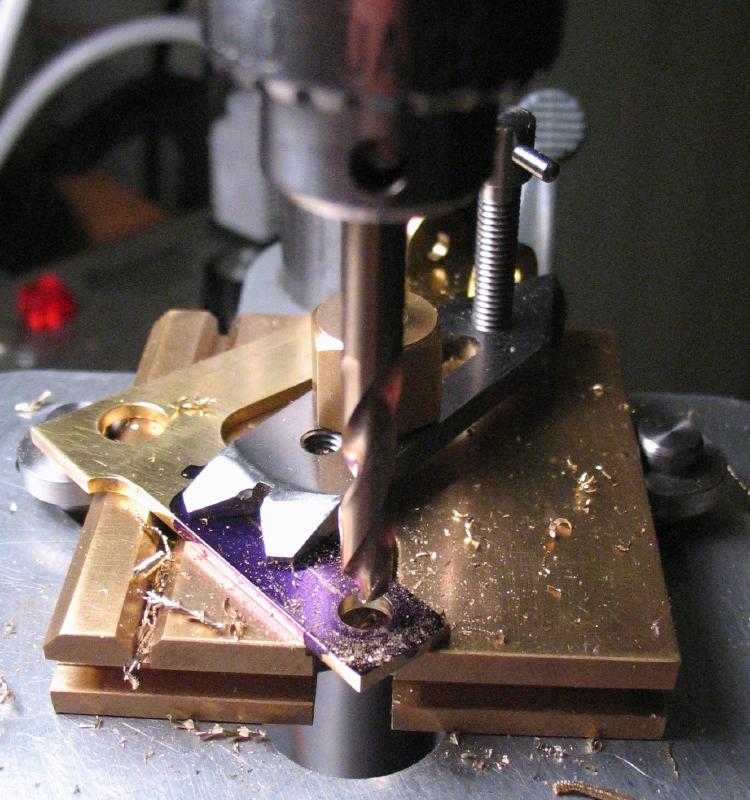
The shape was sawed out with a jewelers saw and the knob attachment position drilled and tapped #8-32. A rear hole is drilled through with a clearance drill for a #4-40 screw. The holes were lightly countersunk with a setting bur. The edges were filed to form the final shape and then polished with 3M Tri-M-ite polishing paper, which goes as fine as 8000 grit or just about a mirror finish. Finally, the protective paper was peeled off to reveal the finished paddle. Dimensions are not given in Mr. Smith's book, so I made a few uneducated guesses when sketching mine out. Comparing photos, I think my paddle is a bit larger than usual, but it can always be filed down and polished again if it becomes an issue.
The paddle-knob bar could then be finished to accommodate the knob and paddle. A clearance hole is drilled for the knob screw and the position for the rear screw is drilled and tapped #4-40. The shape of the end of the bar was filed to roughly match the shape of the knob where they meet. A stock #4-40 round head screw was used to secure the paddle to the bar and was later shortened, deplated and polished but left un-blued. The assembly is upside down in the photo.
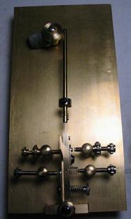
The machining of all the components of the key is complete as well as most of the polishing and plating, except for the base and mainplate, which need their final polish and plating. The photo shows all the final components of the key, ready for a real test.
The pendulum bar, mainspring, and weight rod assembly was nickel plated in two stages (i.e., one end at a time) to minimize plating of the mainspring. The elasticity of the stainless steel mainspring could be affected by the addition of a layer of nickel. There is some overlap where the bar and rod are slotted and riveted to the mainspring, so a small portion of spring was plated, however, the nickel does not appear to adhere to the stainless steel very well and was rubbed off afterwards.
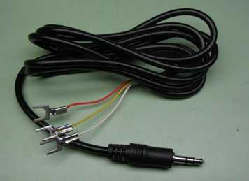
The cable used to connect the key to a transceiver or other equipment is shown below. This example was purchased from Vibroplex, but one can be made from three conductor, audio cable with a phone plug that matches the jack of the equipment used, in this case, it is a 1/8" phone style connection. An Ohm meter was used to check which color wire goes to each of the sleeve, center ring, and tip of the plug. The key can then be matched to the equipment by connecting the colored wires to the appropriate terminals.
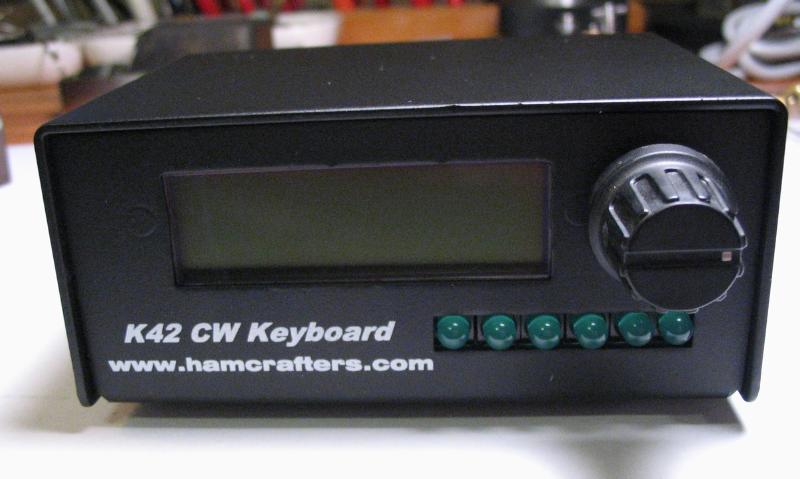
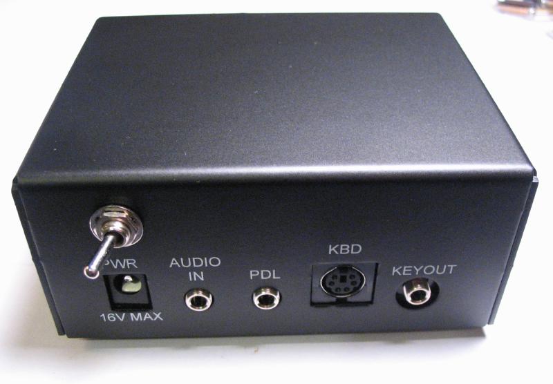
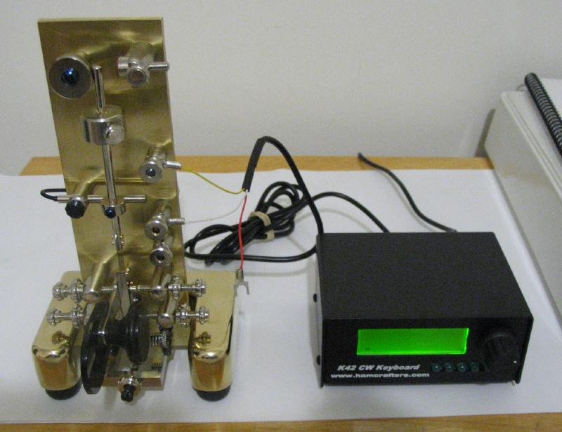
In order to experiment with the key off the air and learn to use it, I built the device below, a K1EL Systems K42C. It has a host of other useful functions for continuous wave (CW) radio operation, including rendering the telegraph key obsolete (if you did not already think so...). The K42 is connected to a PS/2 keyboard and a transceiver to 'decode' received CW into characters on the LCD display and key the transmitter with typed messages and send them at the desired speed, weighting, tone, ratio, etc. The K42 also has a built in code copy practice program. A telegraph key can, of course, be connected to the K42 and used either as an electronic keyer, or in this case, as a 'code-practice oscillator' to experiment with the telegraph key. Both the semi-automatic and paddle-keyer functions of the key can be used with the K42, however, when using the semi-automatic key, it generates a sidetone and will key a transmitter if connected. When the key is setup as a paddle-keyer, the K42 can decode keyed characters and show them on the display. As with other electronic keyers, it generates respective dots and dashes continuously as long as the paddle is pressed. Since this is a 'single-lever paddle,' the 'iambic paddle' functions of the K42 can not be used.
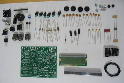
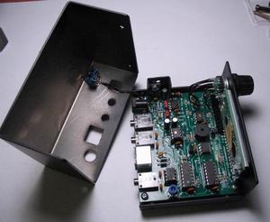
The instructions available on the hamcrafters website are well written and include color photos of the various steps. I did not document my build, but followed the instructions with as little deviation as I could manage. There were a couple part substitutions that were not clear at first. It is a good idea to lay out the inventory of parts that are included in the kit, if only to be able to correctly identify everything while installing them. I added a power switch, so a hole was drilled in the chassis above the power jack. I did not position the power transistor high enough when soldering it in place to match the hole in the heat sink. Since the leads were already trimmed, the heat sink was given an extra hole as well. The first part to solder in place was the power jack and I was a bit rusty with the soldering iron at first, so the power jack is a little crooked as a result and I did not notice until mounting everything in the chassis. There are a couple soldering tasks that require special care, such as installing the front row of LEDs (mine are not aligned perfectly) and the LCD display, but the suggestions provided in the instructions were useful. There are multiple testing points during the build, which require a Volt-Ohm meter, and either a signal generator or a radio receiver. Overall, the kit is very straightforward to put together, I only performed a few steps at a time and lost track of how long it actually took. A few items are needed during the build, but will be needed anyway, such as a power supply, PS/2 keyboard (most of the K42's functions are controlled by keyboard commands), and, of course, a telegraph key.
The key was connected to the K42 with the three conductor wire with phone plug shown above. One lead is not used with semi-automatic keying, which is the tip lead by default with the K42, but this can be changed. The center ring lead is attached to the dash/reed switch terminal and the sleeve lead attached to the upper common terminal. This arrangement is convenient since it is fairly easy to make the key ready for use as a paddle-keyer. The tip lead is attached to the empty dot contact terminal and the reed switch disconnected. The pendulum still vibrates, but the weight can be removed and stop piece used to dampen or practically immobilize the pendulum. Likely not the ideal paddle keyer, but it does work. This could be useful if needing to send at a speed outside the available range of the pendulum weights, instead of switching to a different key, this one can be fairly quickly switched over to use an electronic keyer, such as the K42 or the internal keyer of most modern transceivers.
The speed of the semi-automatic key can be approximated by ear; I connected the key to the K42 CW (in 'bug' mode) and alternately sent streams of dots by pressing the paddle on the key and pressing the number 5, which is 5 dots, on the keyboard. The rates of the dots sent by the K42 can be adjusted in 1 WPM increments and compared to those from the key until they sound about equal. The slowest rate with the larger of the two weights I made is about 20 WPM. With both weights attached at full staff, it slows down to about 15-16 WPM.
For practice, the K42 is set to the same rate as the pendulum of the key (as above) and characters, words, etc. can be sent using the keyboard to compare the with spacing and weighting of what I am sending with the key.
A few extra weights were made, including a fairly large one from a short piece of one inch diameter brass rod that slows the key down to about 14 WPM and seems to be about the largest weight that will work.
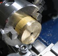
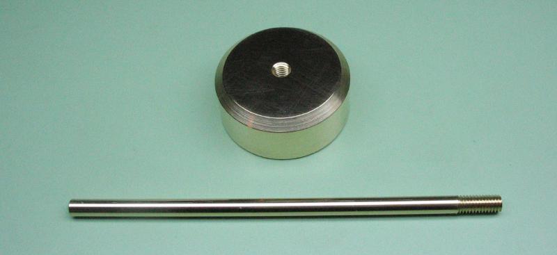
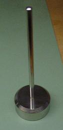
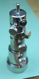
A caddy was made to hold the weight collection while they are not in use. It was made from a piece of 1.25" brass rod from the scrap bin, and was faced, drilled and tapped M4, and bored slightly to form a recess. It was reversed into the 6-jaw bezel chuck and faced, turned and chamfered. A length of 5/32" brass rod was threaded M4, and the other end rounded over with a cup bur. Both pieces were then nickel plated.
The base and mainplate were given their final polish and nickel plated. Mr. Smith recommends having most of the components of the key professionally plated, however, I've attempted to carry out all the plating using the same setup. A larger container is needed to accommodate the base and mainplate. The results with both were less than perfect, and could use some more time in the plating solution as the coverage is incomplete and somewhat uneven as well. However, this will do for now...
