Lapping and Sharpening Jig
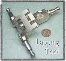
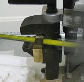
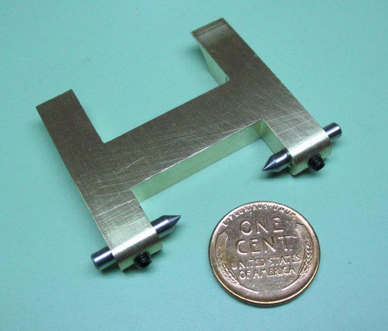
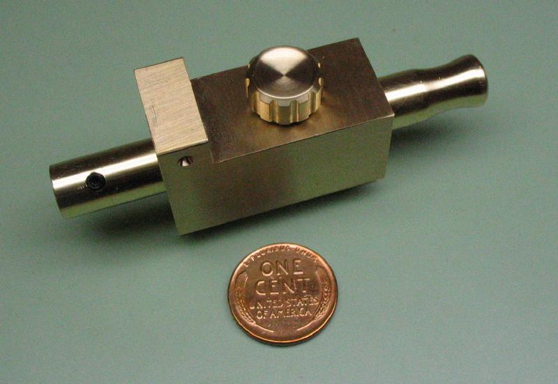
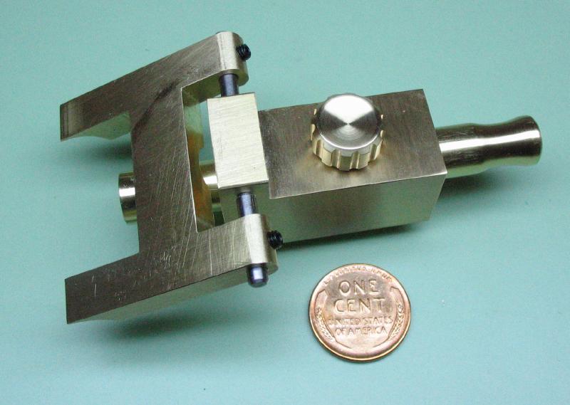
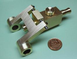
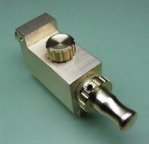
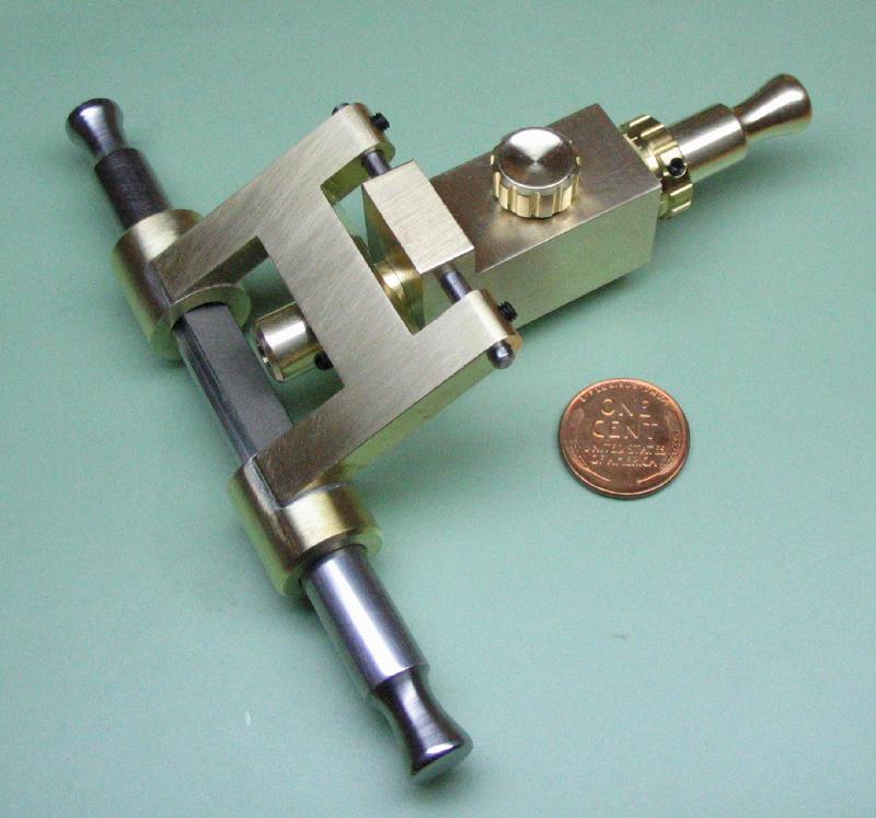
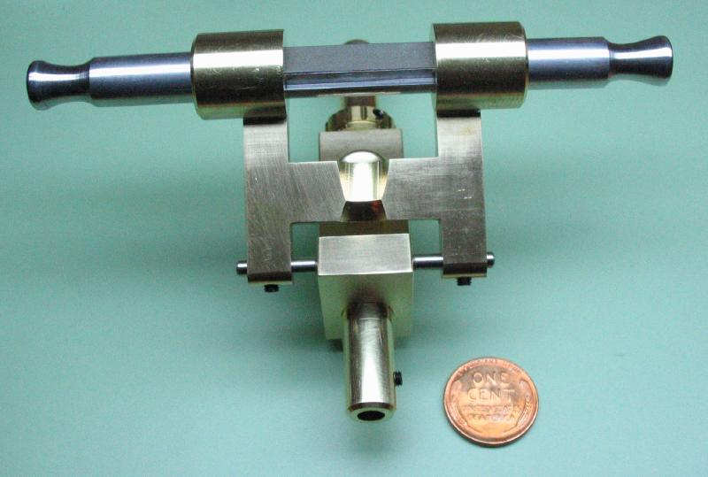
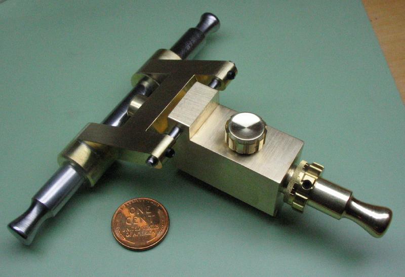
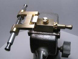
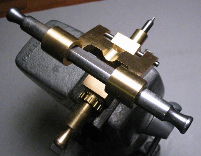
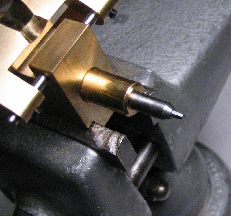
J. Malcolm Wild depicts a tool in "Wheel and Pinion Cutting in Horology" that is intended for lapping or sharpening small tools, such as fly cutters, gravers, drills and other small bits. There are several photos of the tool as well as a description of its use in this book and there is what appears to be a more refined version of the tool on his website as item JMW 1587. Dimensions are not given in the book, but they can be approximated. I made use of brass stock that I had on hand. The base of the tool has a bore for a tool-holding mandrel and also has pivots for a hinged bracket that acts as the guide for the lapping tools. This arrangement allows both the tool to be sharpened and the laps to be rotated in different axes, which can accommodate a variety of different geometries.
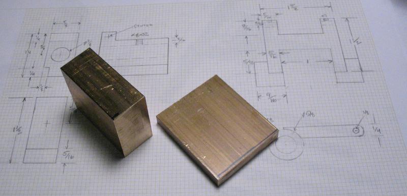
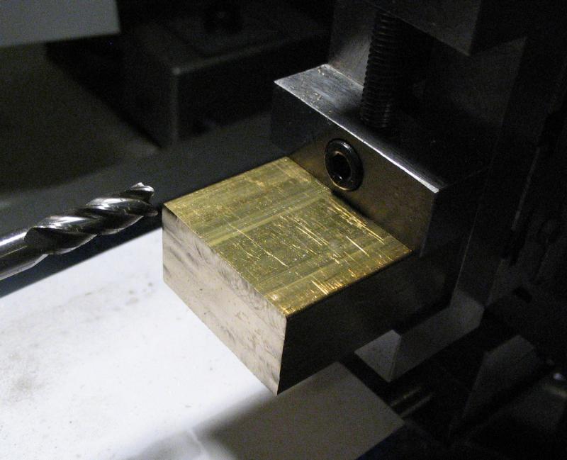
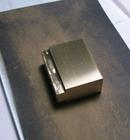
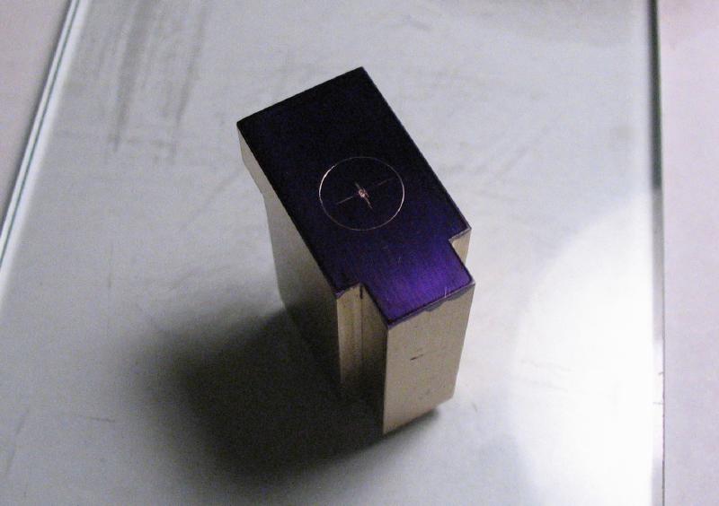
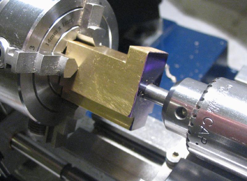
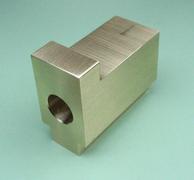
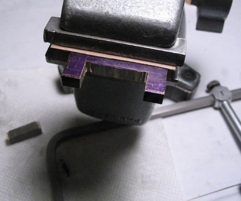
The base of the tool was made from 5/8" x 1-1/4" brass bar (type 360). A roughly 1-1/2" long piece was sawed off, as shown above, and the sawed edges milled to help make them flat and square to the extruded sides of the brass stock. A step was milled on either side that is about 1/4" wide and 1/8" deep. These steps are for holding the finished tool in a vise. Afterward, the work was coarsely polished on 400 grit emery paper to remove tool marks and generally smooth the surface and improve the appearance, which can be helpful when scribing out dimensions.
The top face was scribed to mark out where material will be removed, which was then done by milling.
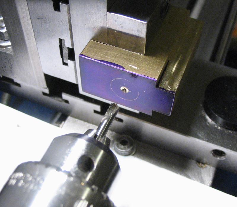
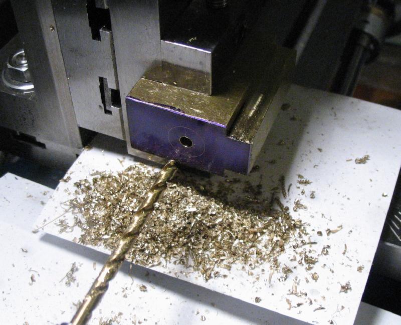
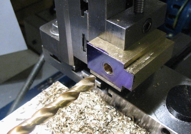
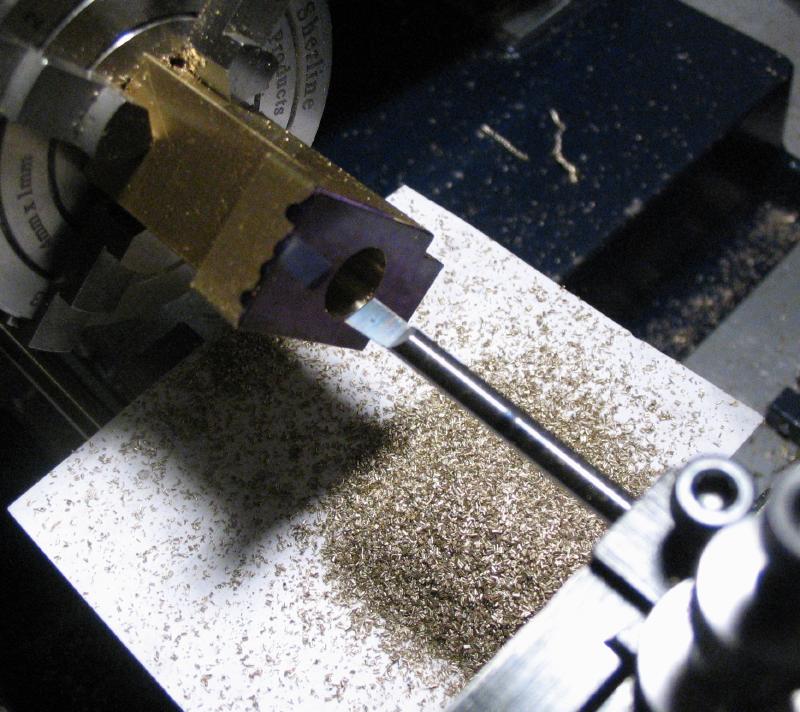
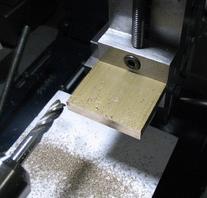
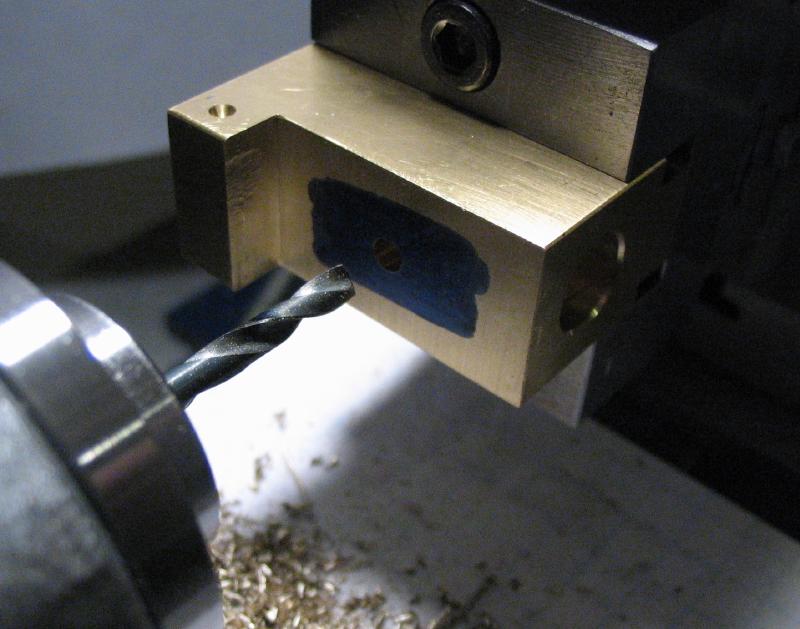
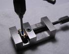
The location for the central bore was scribed and center punched. A divider was used to lay out the approximate diameter of the finished hole. This hole is for the tool holder. The work was mounted in the machine vise and the location found and spot drilled, and drilled through 1/8" first and then opened up to 1/4" (the largest drill on hand of the necessary length).
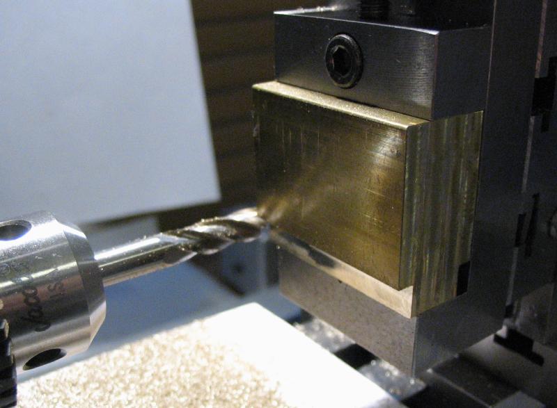
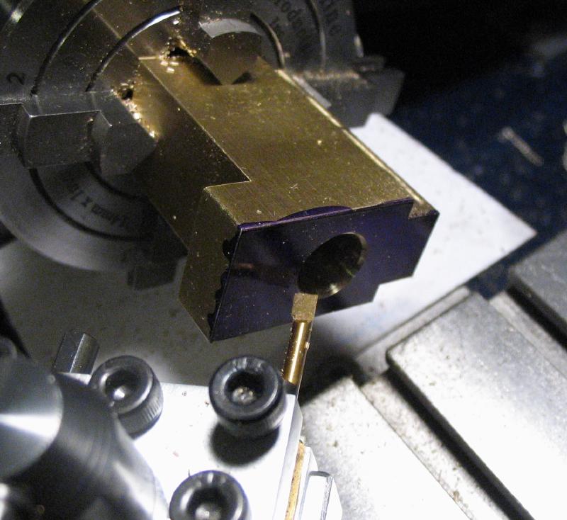
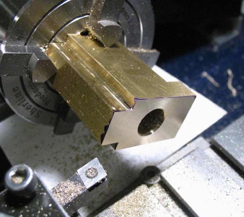
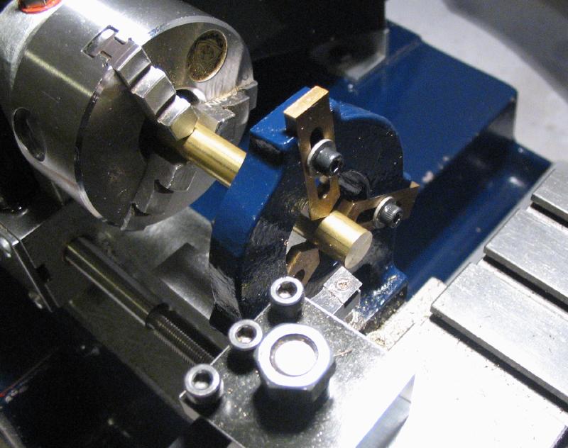
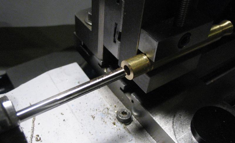
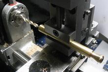
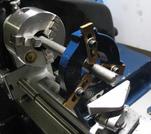
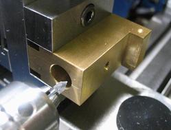
The work was moved to the 4-jaw chuck and a piece of 1/4" drill rod held in the tailstock to help bring it onto center fairly quickly. The hole was then bored open to pass a piece of 3/8" diameter brass rod with a snug fit. This requires a boring bit with a long reach (at least 1.5"), this one just made it to the other end of the hole. The corner of the bored hole was chamfered using the topslide and a small boring bit, and the face turned to true the surface to the bore but only needed a light cut.
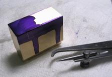
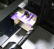
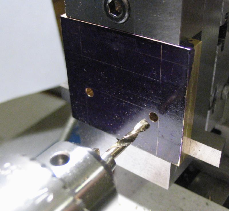
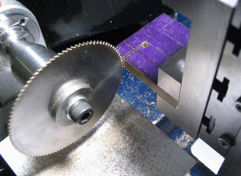
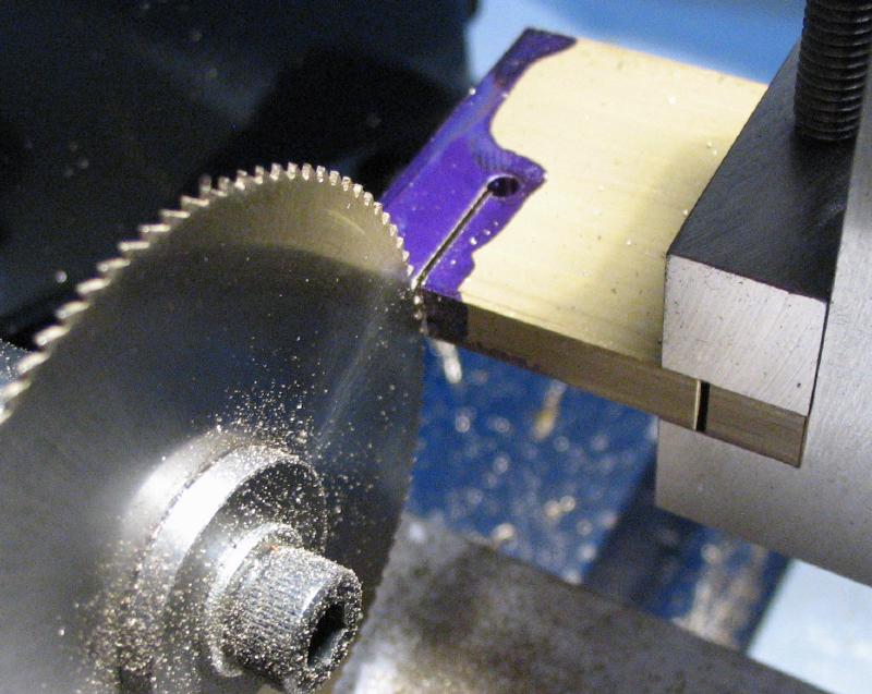
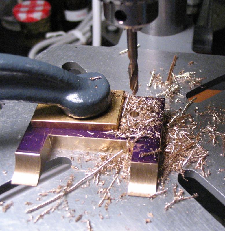
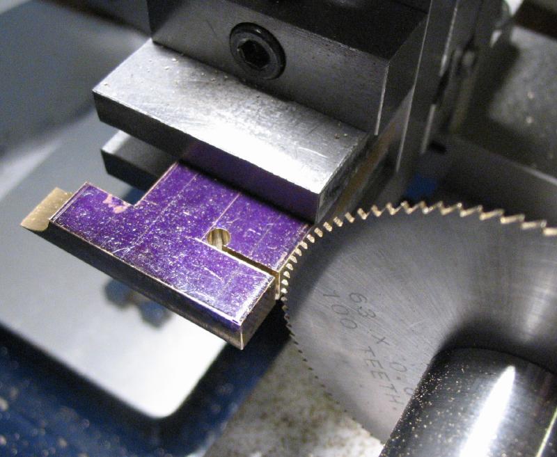
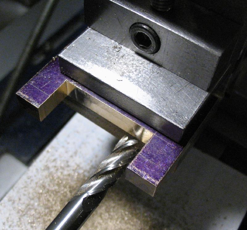
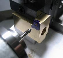
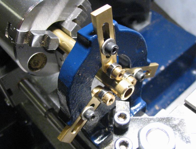
The swinging hone guide bracket was started from 1-1/2" x 1/4" brass bar. A length a little over 1-5/8" was sawed off and the sawed edges squared up using the vertical slide on the lathe with an end mill. One face of the plate was coated in layout blue and the dimensions scribed out. The longer pair of arms were started first since they will involve a more difficult machining step. The 'corners' were drilled first, and a slotting saw used to make the first two cuts.
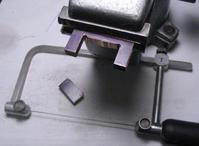
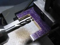
The sawing was completed by hand with a jewelers saw, which I obviously had very little control over. This rough edge was finished with a 1/4" endmill. The rounded corners were squared and the arms brought to desired thickness with light cuts using the sides of the endmill.
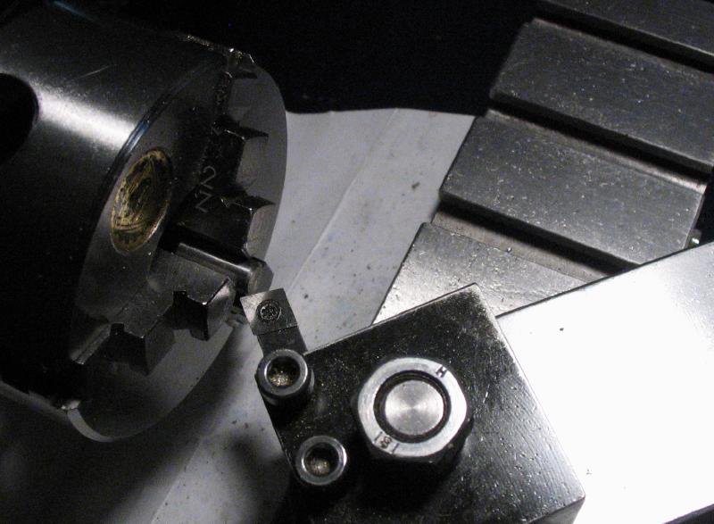
An arbor for a fly cutter was made from a length of 1/2" cold roll steel rod (12L14). This was my last piece of 1/2" stock, but appears to be just long enough to work. It was mounted in the 3-jaw chuck and supported with the steady rest to face, chamfer, and center drill each end.
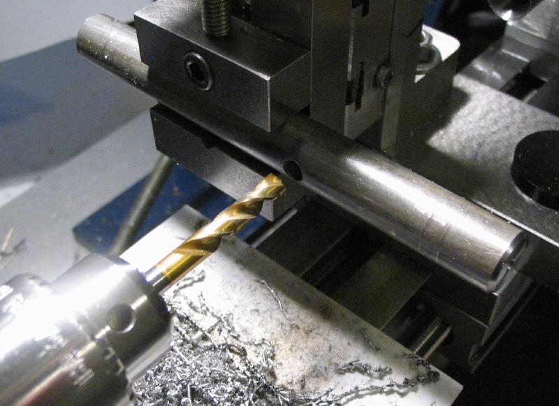
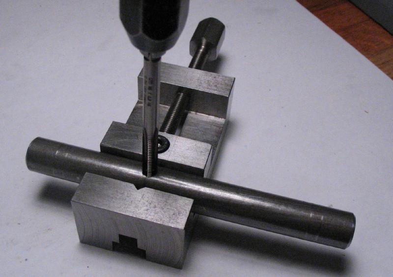
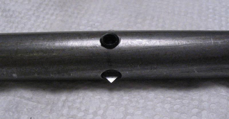
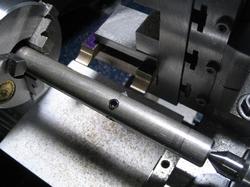
The position for the fly cutting bit was drilled through 4.9mm (something slightly smaller would be better) and reamed 5mm. The work was rotated 90 degrees by eye with a length of 5mm drill rod in the reamed hole to help. The position for a set screw was drilled 4.2mm and then tapped M5x0.8.
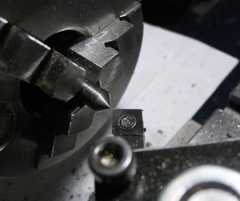
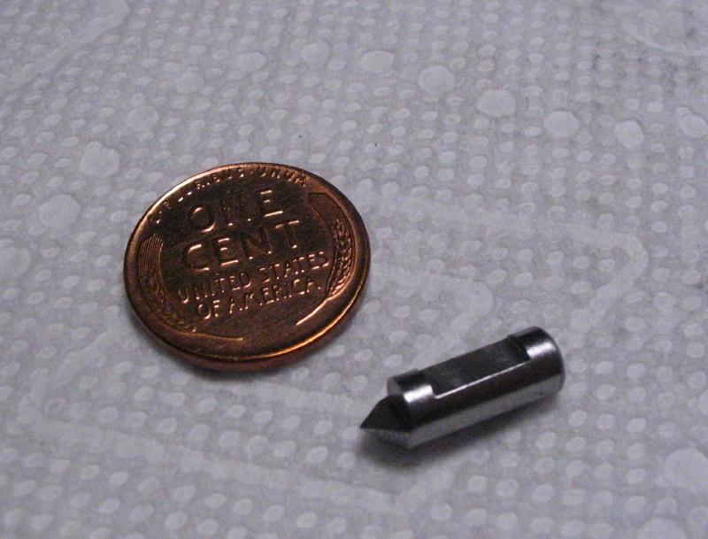
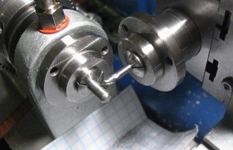
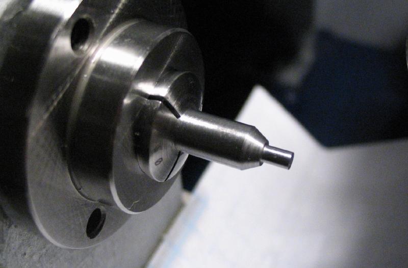
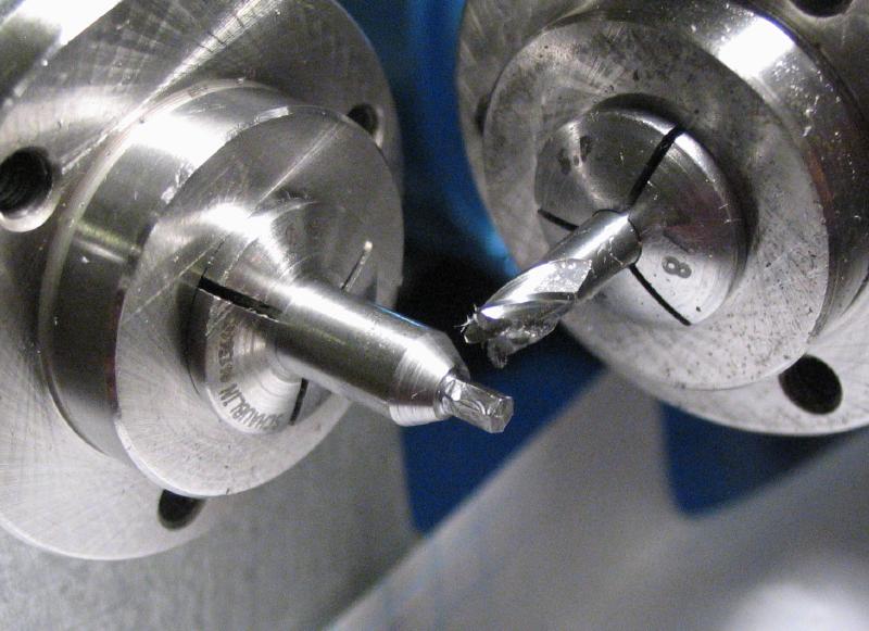
A fly cutting bit was made from 5mm oil hardening drill rod. The rod was turned to a 45 degree point and the tip milled to half its width with a 1/8" endmill. A flat was milled for locking the bit in place during use. The bit was parted off and the parted face chamfered using the top slide.
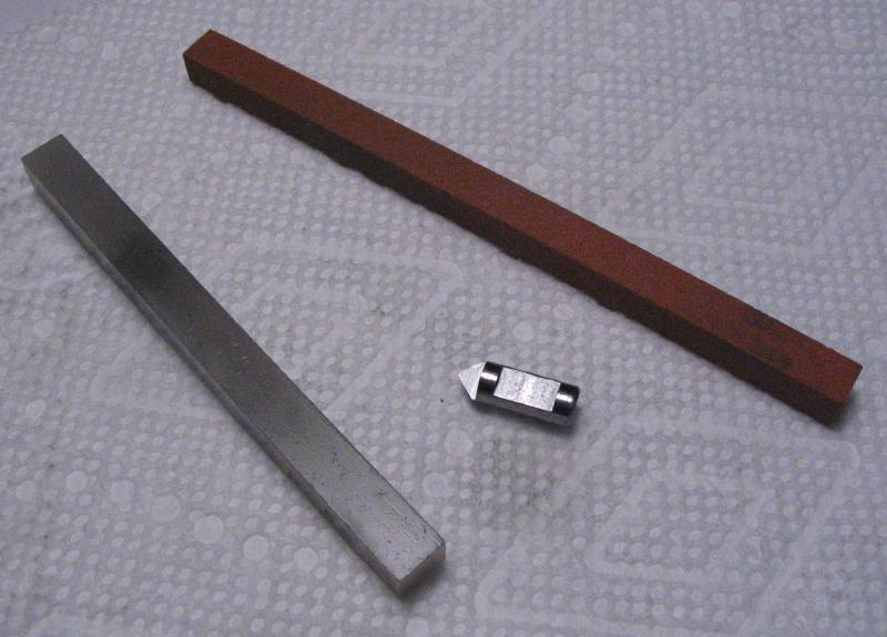
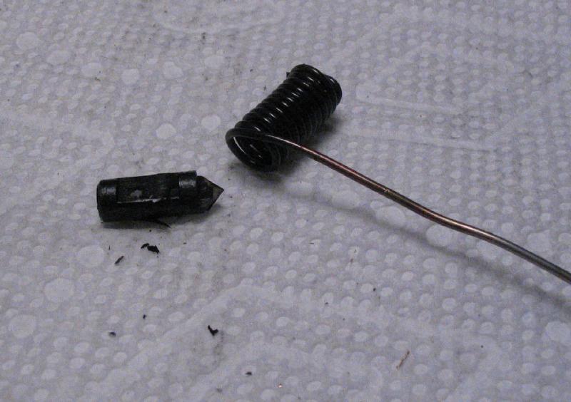
The fly cutter was smoothed and flats polished with an India and Arkansas stone slips. This was done by hand, of course, and this is the sort of task that will be suited for the finished tool. The cutter was hardened by raising to red color with a torch and holding it in a stainless steel small wire basket. The cutting face was repolished, but otherwise used as is and in the fully hard condition. It was mounted in the arbor and the tip extended 1/16" from the surface of the arbor and locked in place with the set screw.
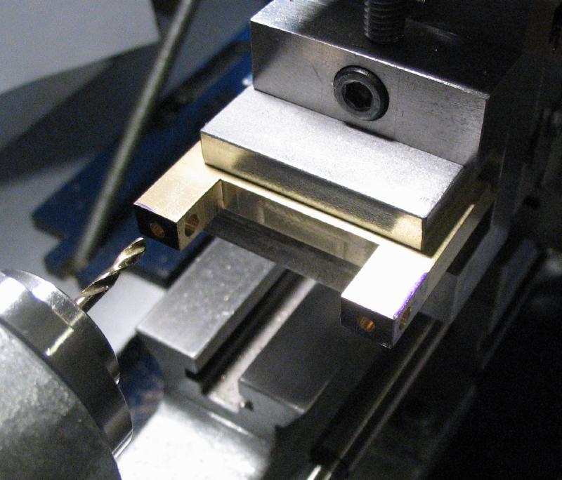
The bracket was mounted in the machine vise and on the vertical slide. The tip of the fly cutter was positioned 6mm from the surface, and fed into the work with 0.25mm deep passes milling each arm with each pass. The fly cutter leaves a 5/16" radius that will mate with the 5/8" diameter tube below.
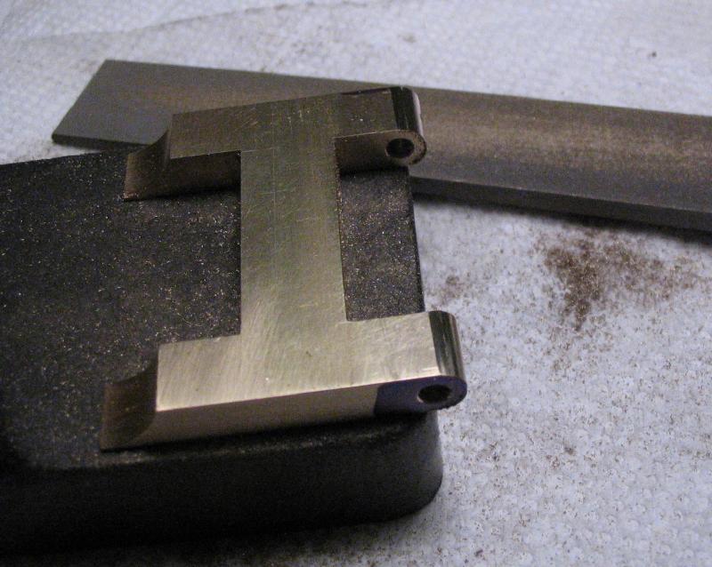
The pivot arms on the other side of the bracket were cut out next. As was done above for the other arms, the corners were drilled first and the center portion sawed out, and the space then squared up with an endmill. The width of the space is 1 inch, but this should be reduced to 7/8" or so.
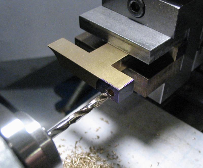
The locations for the pivots were scribed out at about 1/8" from each side, but some extra length would be preferred on the end for the set screw threads. The scribed location was found, spot drilled, drilled 0.110" and then reamed 1/8". It would likely be preferable to drill and ream both holes at the same time, but my available drill bits were too short.
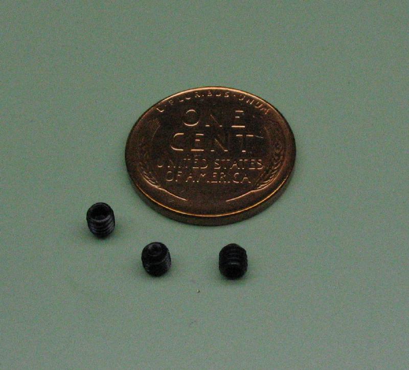
The ends are drilled 2.5mm and then tapped M3x0.5 for set screws to lock the pivot centers in place. The ends of arms were then rounded over with "hand" files. Stock M3 set screws that are 3mm in length were used.
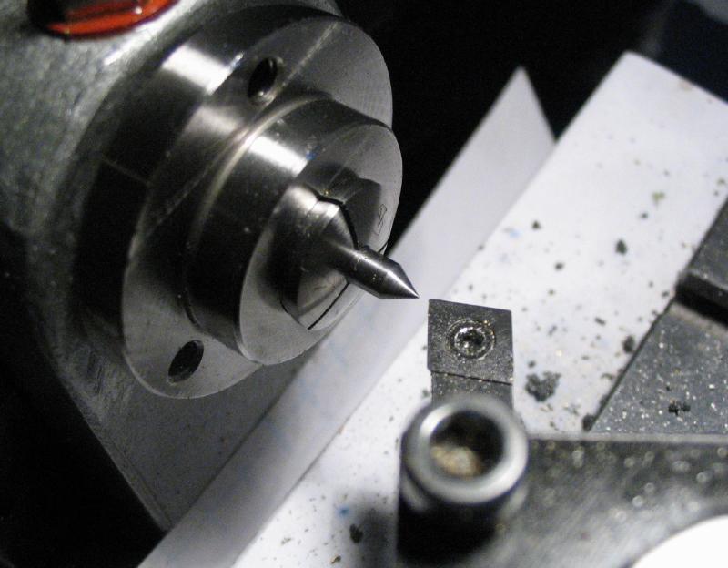
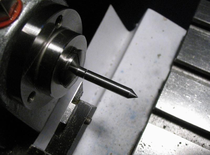
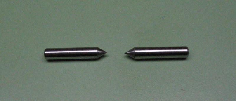
The pivot centers were made from a length of 1/8" oil hardening drill rod. The rod was turned using the top slide of the lathe to produce a 60 degree point on each end. The rod was then parted in half, and the parted ends faced and chamfered.
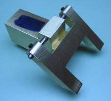
The pivot locations were scribed onto the base and then center drilled with a #000 combination center drill and 60 degree countersink. The bracket could then be tried on the base to check the fit and movement of the bracket.
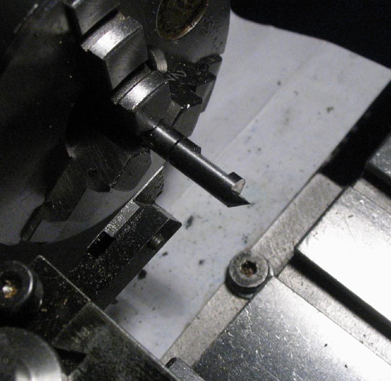
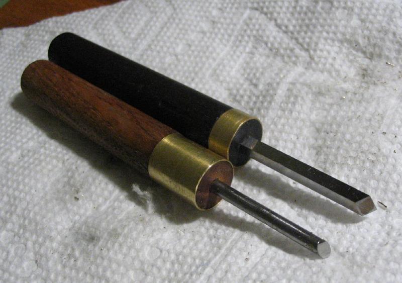
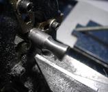
A tool holding mandrel was started from 3/8" diameter brass rod. A 3" length was mounted in the 3-jaw chuck and supported in the steady rest. One end was rounded over and a short section turned using a graver made from round drill rod to form a radius that will act as a grip for adjusting the tool in use.
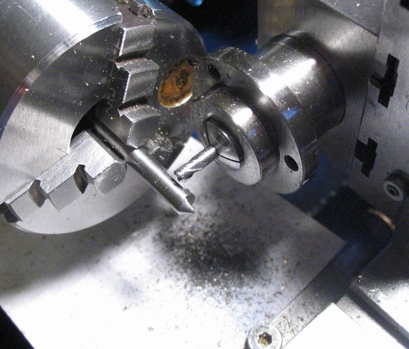
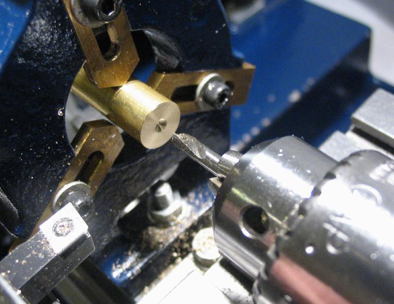
The work was reversed on the lathe and the other end faced, spot drilled, and drilled 4.9mm (not shown). At this point I realized my 5mm reamer would not fit within the space available, so the work was repositioned in the vertical slide with the reamer mounted in the headstock. Less than ideal setup, but alignment was preserved as best as I could under the circumstances.
The mandrel was centered in the machine vise; Mr. Wild's micrometer centering tool is handy for setting these sort of things up. The position was drilled and tapped M3x0.5. Another 3mm long M3 set screw was used as a locking screw.
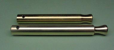
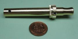
A longer tool holder (about 4") was made in much the same manner, but drilled and reamed using the vertical slide for both steps. The grip is a bit more elaborate as well.
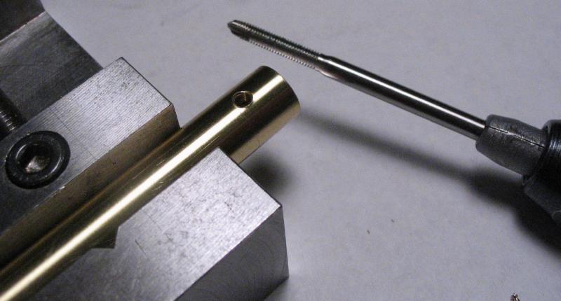
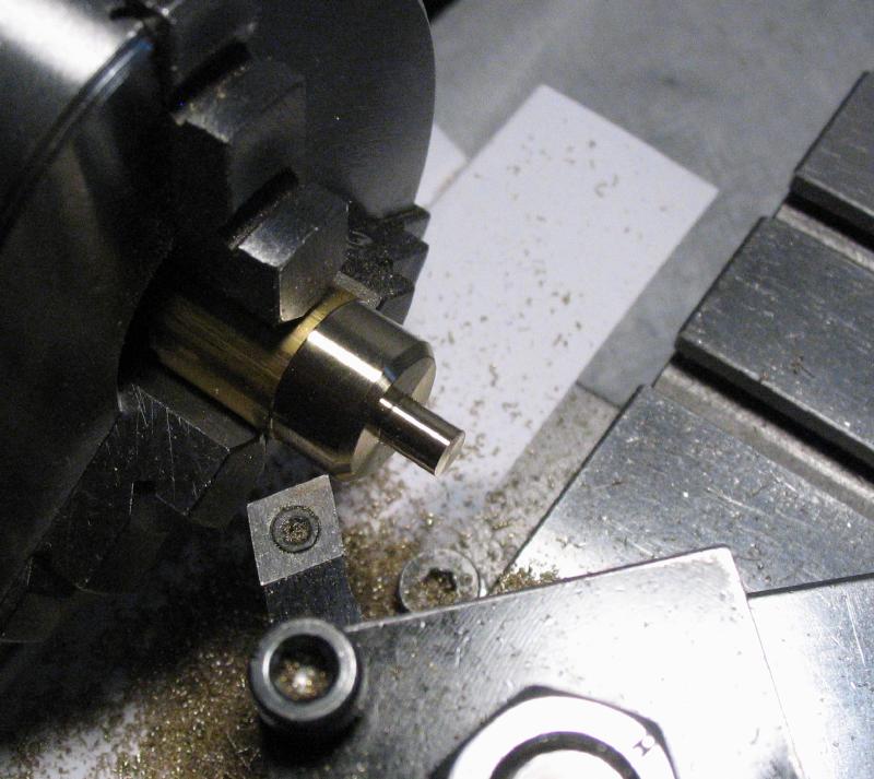
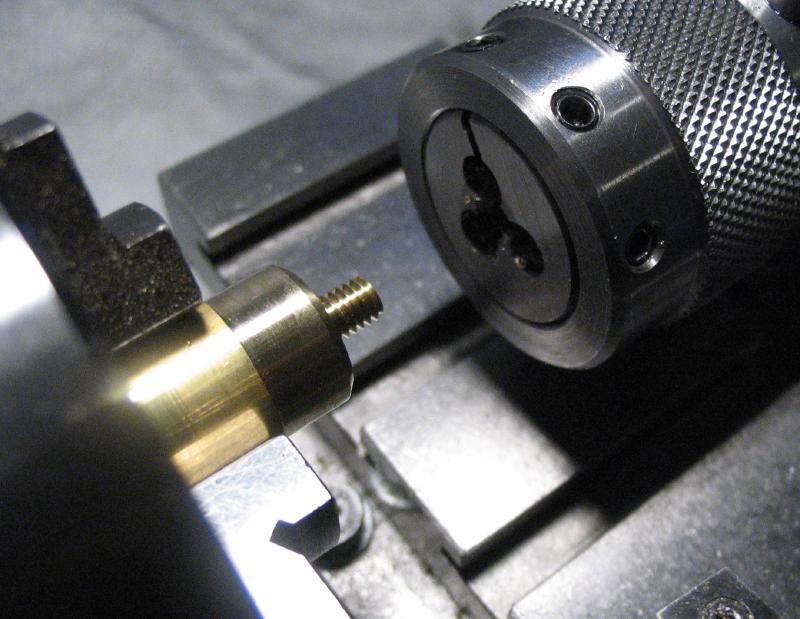
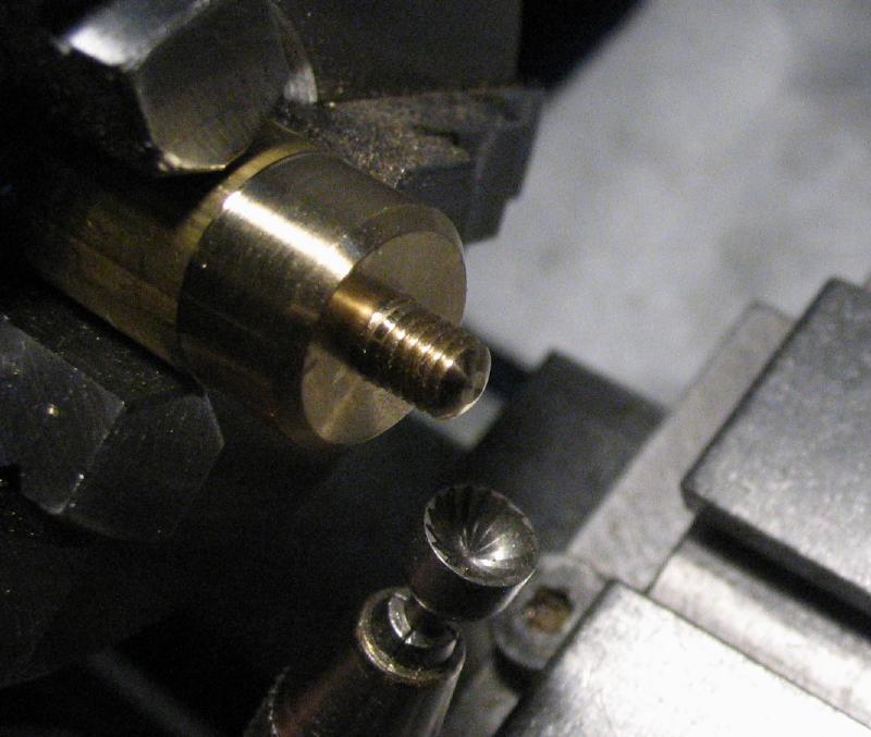
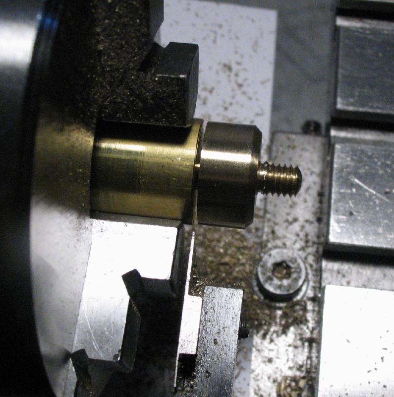
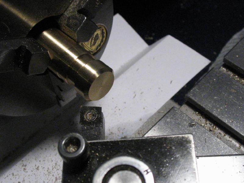
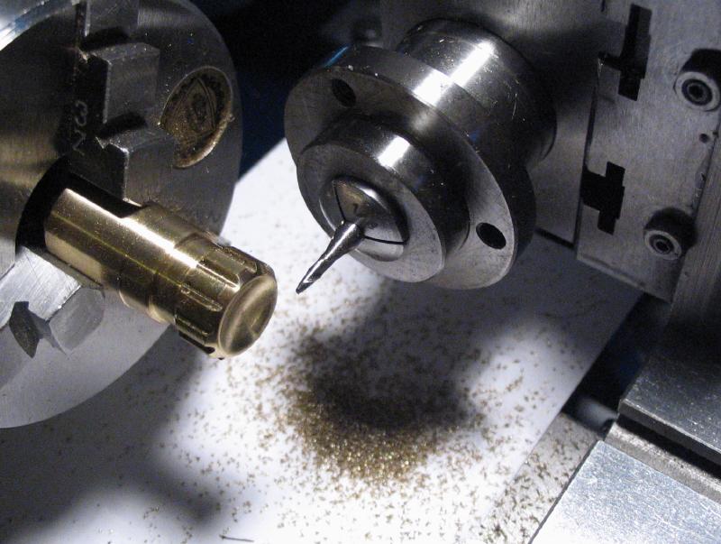
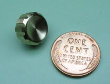
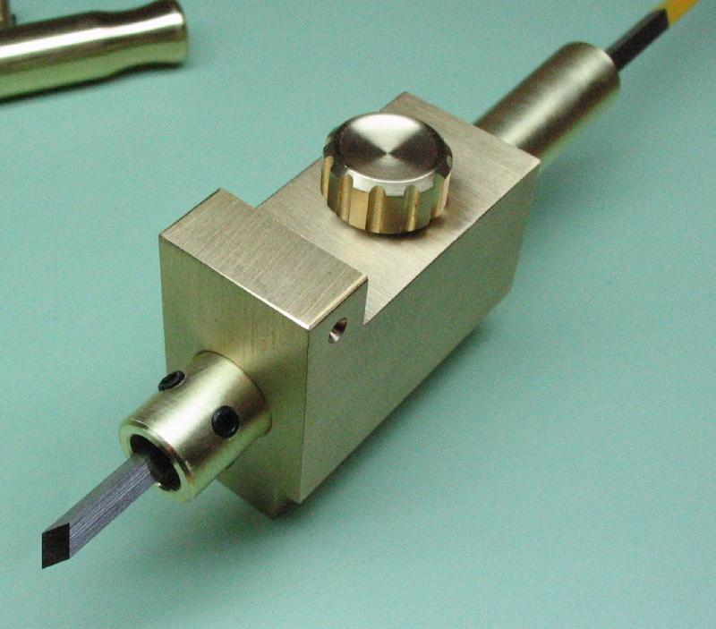
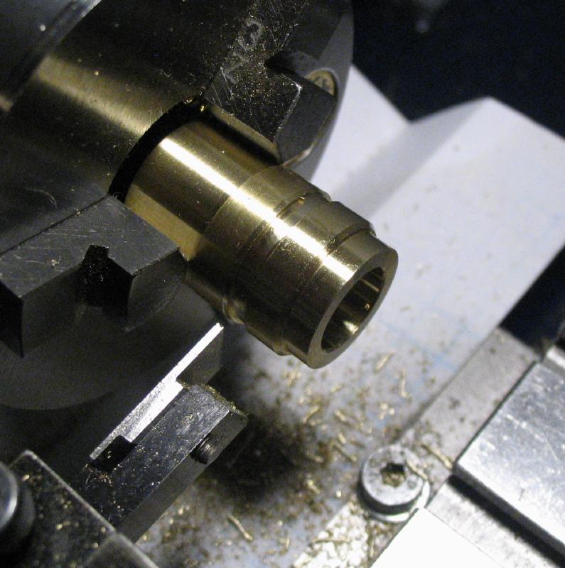
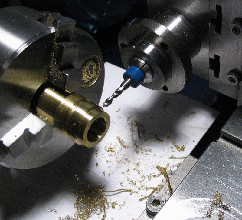
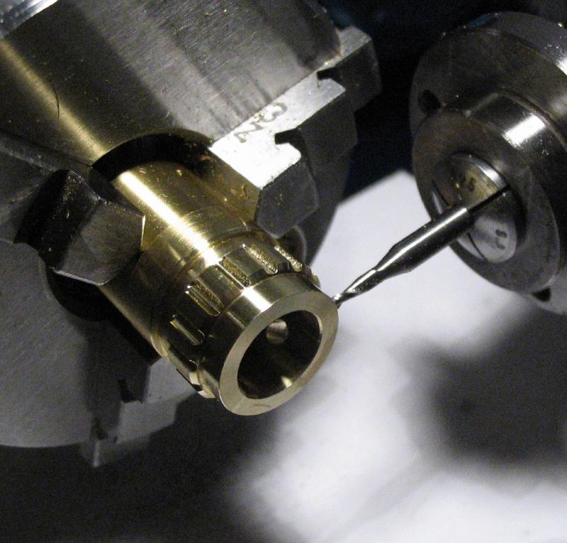
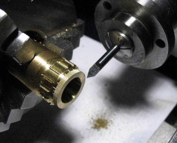
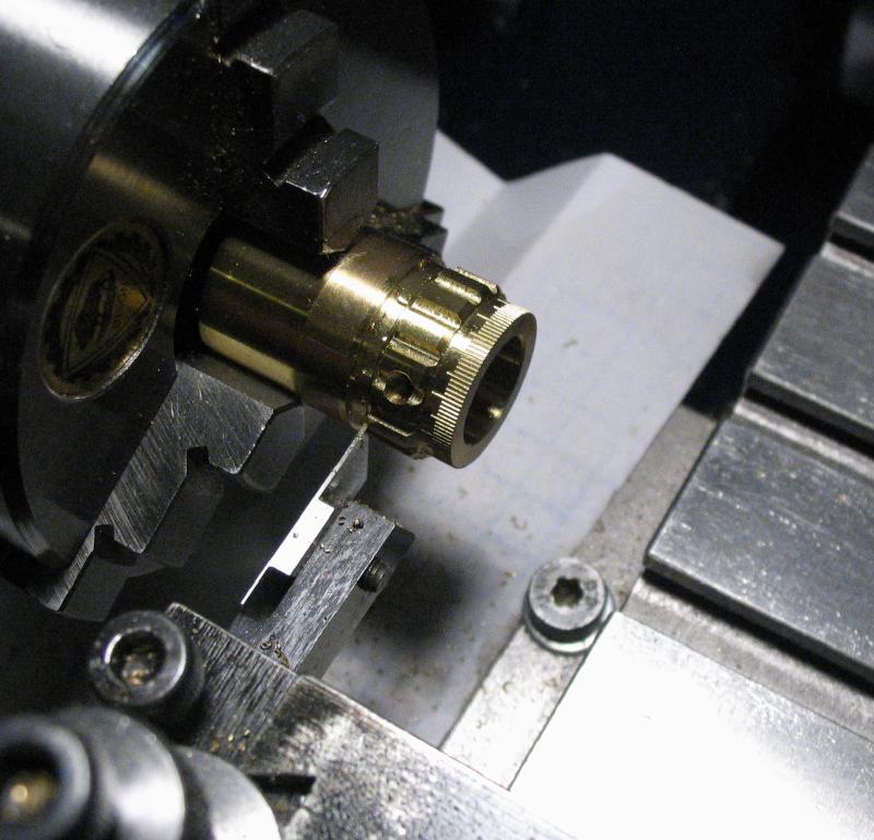
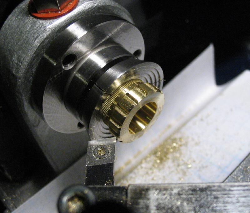
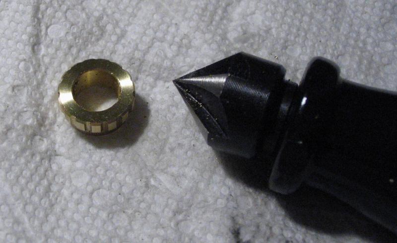
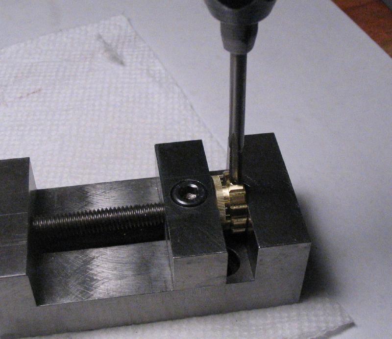
The base was drilled and tapped M4x0.7 for a screw that locks the tool holding mandrel in place. The thumb screw was made from a short piece of 1/2" brass rod. It was turned and threaded M4 and then parted off. An arbor was prepared from another short piece of 1/2" brass rod and the screw mounted. The parted face was chamfered and the face turned with a round graver to give it a concave surface. The headstock was locked and the milling spindle used to mill grooves around the periphery.
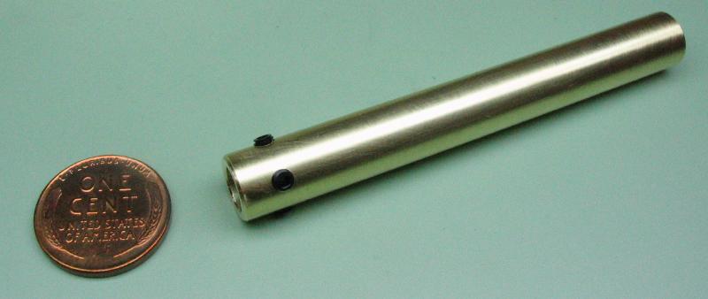
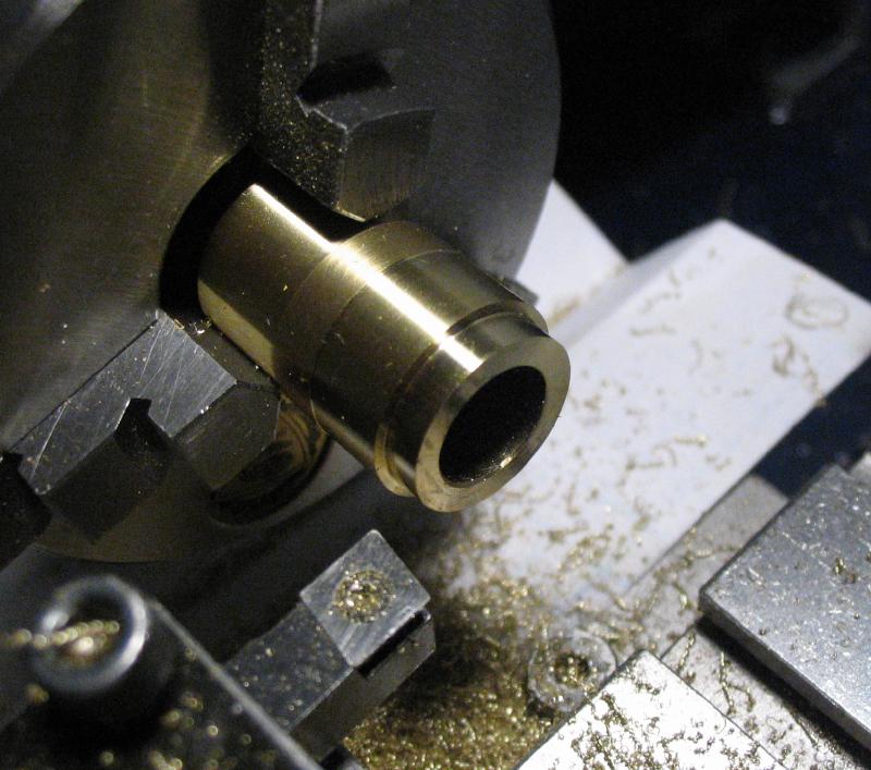
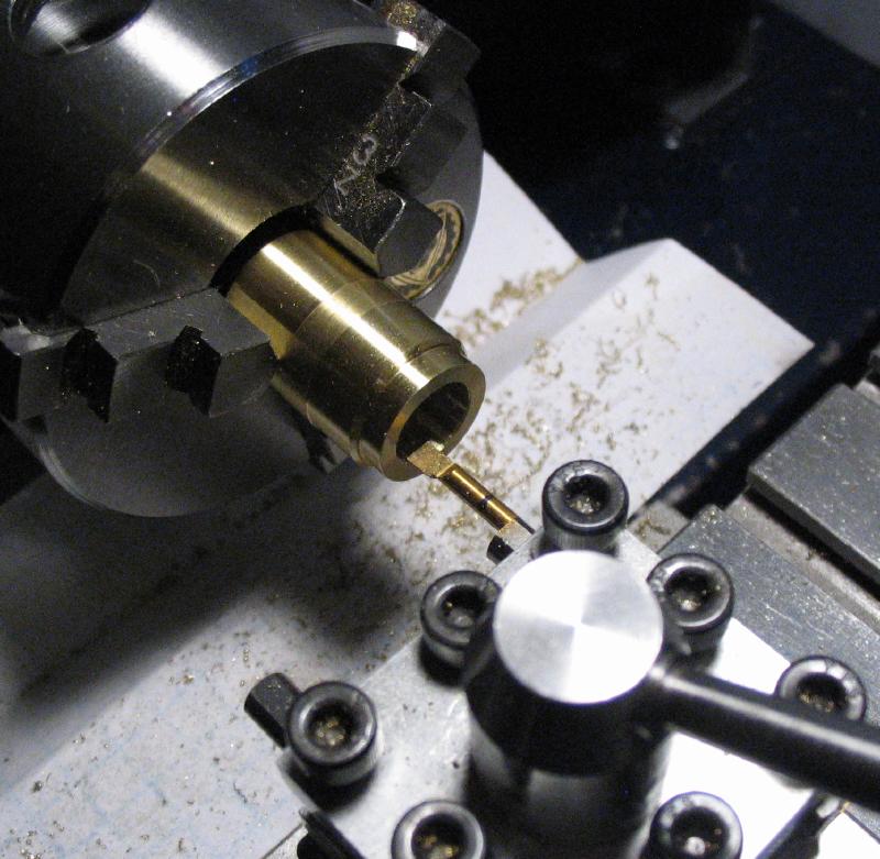
Various types of tool holders can be made. One with four opposing set screws was made for holding small square tools, with gravers specifically in mind. It is made from 3/8" diameter brass tubing with an internal diameter slightly under 1/4". Starting with tubing avoids the need to drill through a fairly long length of solid rod. The ends were faced and chamfered using the steady rest and a new set of ball bearing inserts. I made this holder later on but describe it here for continuity. It was after spending time with the steady rest in making the lap rods below that I was inspired to make the new bearing inserts.
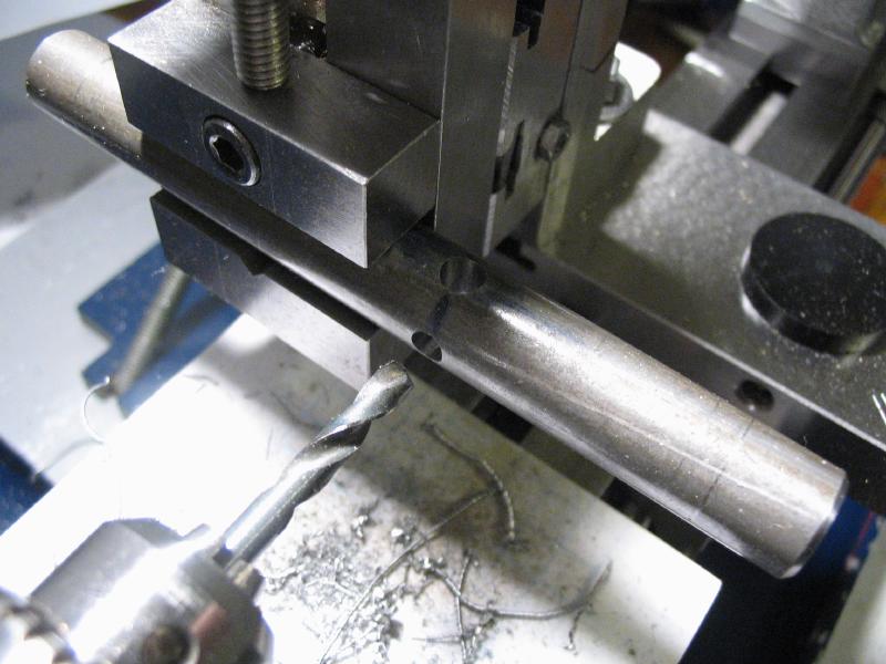
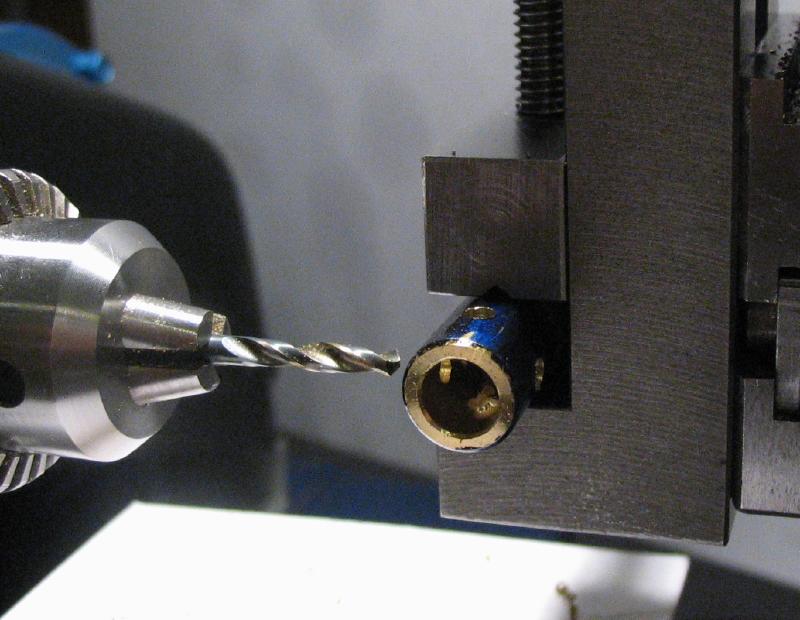
The tube was polished with emery paper to fit the base, and then moved to the vertical slide and vise to drill four 2.5mm holes as accurately by eye as I could! These holes were then tapped M3.
Four nylon-tipped set screws were installed, and a Vallorbe graver installed to try the arrangement out.
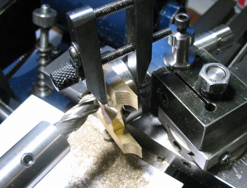
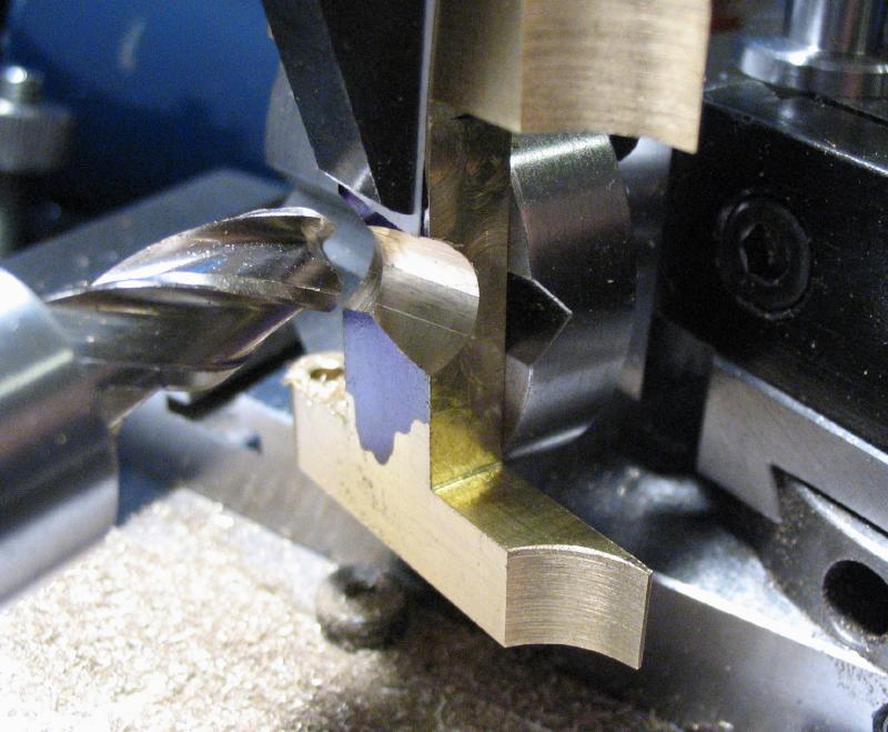
The bracket was fixed to the Cowells tailstock drill pad with a toolmaker's clamp, which was then mounted in the collet holding tool post and fixed onto the top slide. The toolpost was square to the top slide, and the top slide set to 20 degrees. The tool block can be raised or lowered and its spindle rotated to bring the work onto center and a 3/8" ball-end mill, held in the endmill arbor, was used to mill a channel across the center of the bracket to give an increase in reach. After carefully adjusting this crazy setup and milling a couple millimeters, I realized it was upside down! Fortunately, I caught this in time so that the error should not matter, except for aesthetics. Also, this channel may be enlarged with a file at a later time if a larger size mandrel is made.
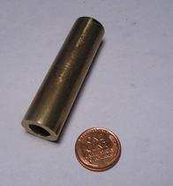
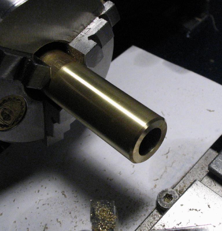
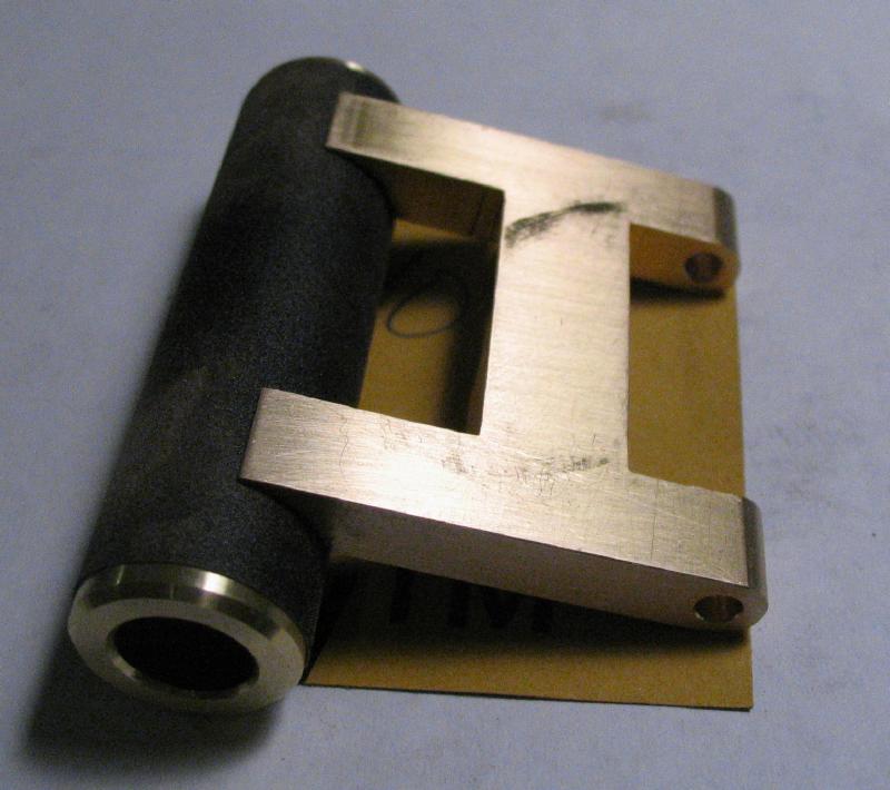
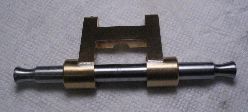
The guides were made from thick-walled, brass tubing. They could be machined from solid rod, but tubing was available that is listed as low-lead, hard-drawn, 330 grade. The tubing has a 5/8" outer diameter and 0.37" (0.005" under 3/8") inside diameter. A length a little greater than 2.25" was sawed off and the ends faced and chamfered. It was lightly polished while on the lathe with 600 grit emery paper. Emery paper was then wrapped around the tube to put a final finish on the mating radii of the bracket arms. This helps remove any small gaps remaining as a result of the radii not matching the tube diameter exactly.
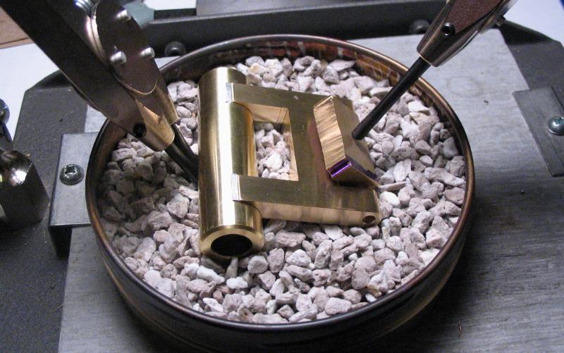
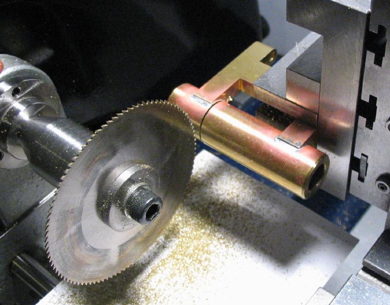
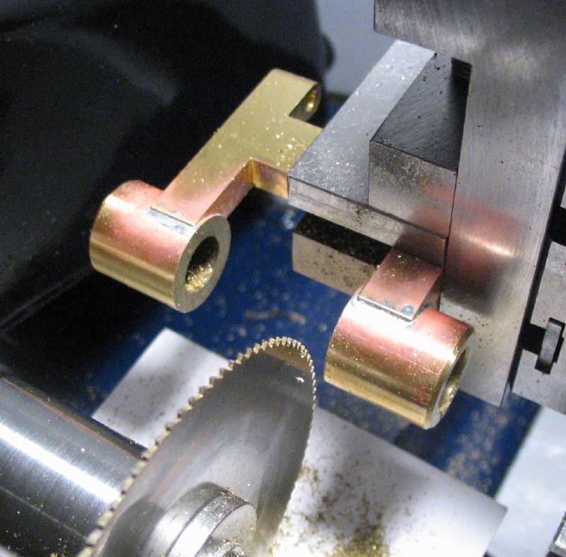
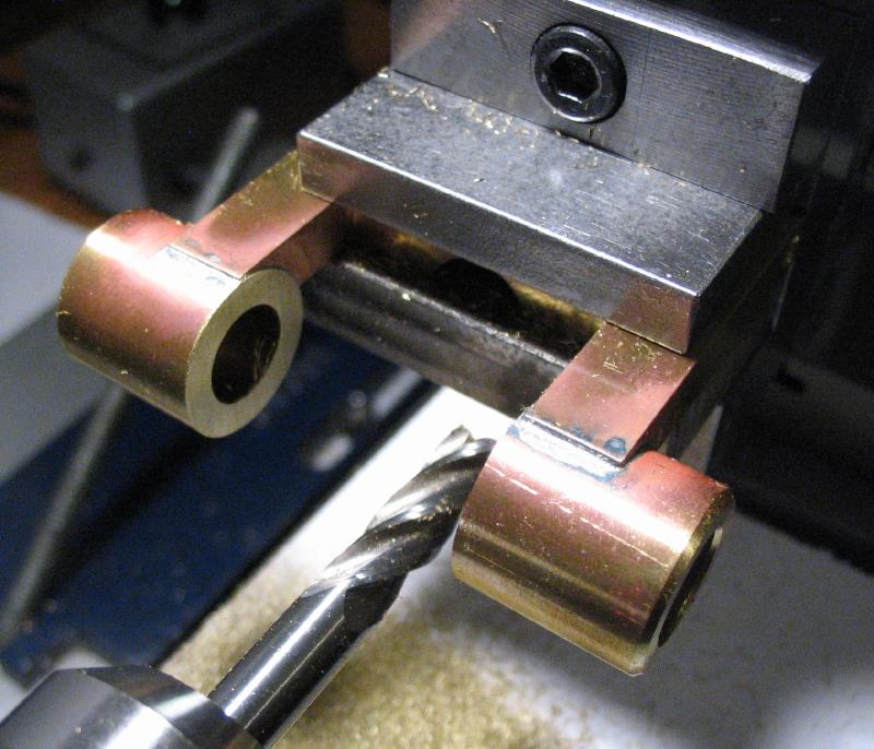
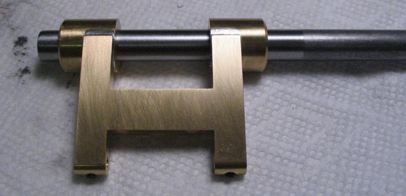
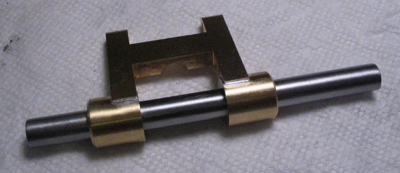
The radiused ends of the bracket were brushed with a coat of flux and then assembled with the length of tubing and the extra hands of the soldering station used to steady everything in place. Small pieces of Stay-Brite silver solder were flattened and trimmed to shape and placed next to the top of each joint. The work was then brought up to temperature with a propane and oxygen torch. My thinking was that the best way to assure the two guide tubes are aligned with each other is to solder them in place as one piece. The work must then be sawed open, which was done with a slotting saw on the lathe and the sawn edges squared up with the sides of an endmill.
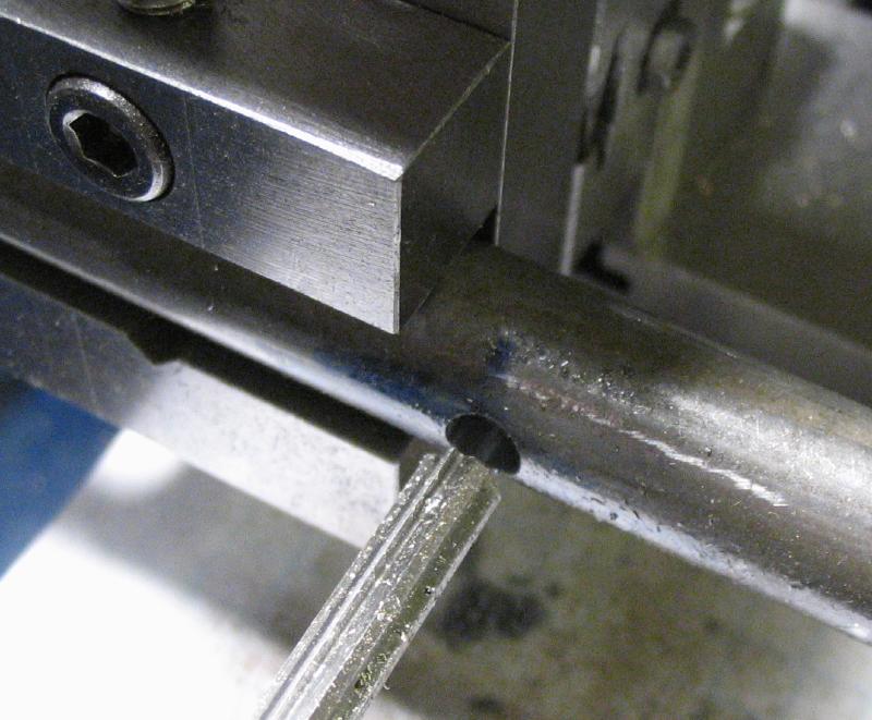
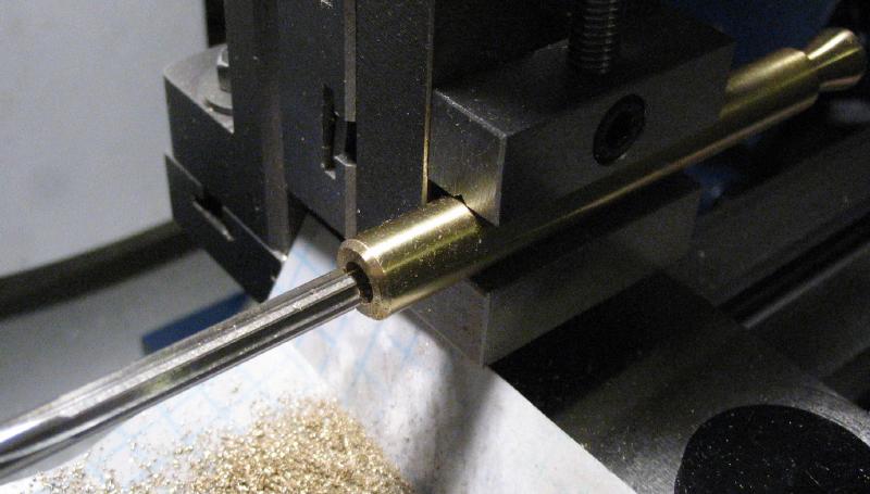
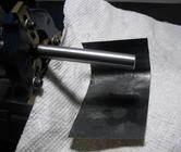
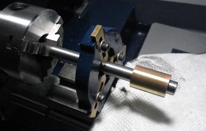
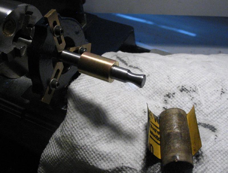
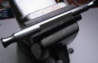
The bore of the tubing is slightly under 3/8" and I am planning to use cold roll steel for the lap rods, the surface of which is fairly rough and pitted, so they will be reduced to fit the tubing. Less than 0.1mm of diameter needs to be removed for a good fit to the tubing, which would be difficult to turn such a small amount end-for-end without being between centers. Instead, the diameter was reduced with hand files and emery paper (400 to start and 800 grit to finish) on a piece of cork. I didn't use the cork initially (as in the photo) but this tended to reduce the end of the rod more aggressively. Periodic checks along the length with a micrometer was used to find high spots, and the scrap piece of tubing that was sawed off above was useful for testing as well. A diameter of 9.42mm seemed to give a good, non-binding but tight fit. The contrast in finish can be seen in the photo of the half finished rod being test fit to the tool. The reverse end was finished in the same manner.
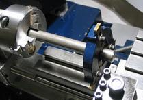
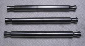
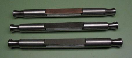
Separate lapping rods will be needed for each abrasive. I am initially planning on three and these were made from 4.5" lengths of 3/8" diameter cold roll steel rod (12L14). One was started above to determine the final diameter needed, and a method for producing it, but this step will be otherwise done after turning. For these turning steps, the rods are held in the 3-jaw chuck and supported with the steady rest, which can score the surface where the steady-rest fingers contact the rod, so likely better to do this work first. The T-rest was setup and as with the tool holder above, gravers were used to round over the ends and turn small radii that will act as a location to grip the rod while working it back and forth during use.
The three lap rod blanks are shown below. The style of grip improved with each successive attempt at turning one. However, just about any shape will do here.
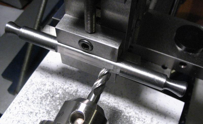
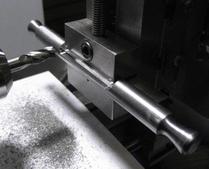
The rod was mounted in the machine vise with a 1/4" square tool bit underneath to raise the rod above the vise jaws. A flat for the abrasive shim was milled that is about 7mm wide and 1-5/8" in length. In order for the hone to reach into the corners of the work, a step was milled after rotating the rod 90 degrees in the vise. The step is 2.5mm deep from the flat, which should be sufficient to work with 5mm diameter fly cutters, at least. Greater than half the circumference of the rod must be left intact so that it will maintain alignment in the brass tube guides.
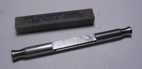
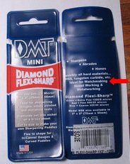
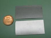
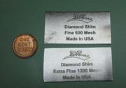
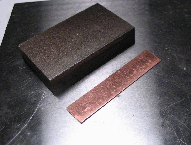
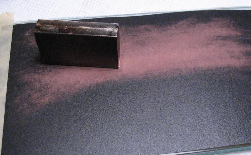
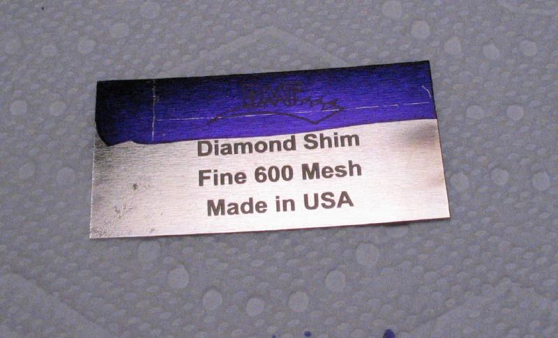
The abrasives for two of the hones are DMT Flexi-Sharp, which are 0.006" thick brass shims that are coated on one side with a diamond abrasive 'set into nickel' and are available in four grades of coarseness. These are the two finest and are listed as "Fine" (600 mesh, 25 micron) and "Extra-Fine" (1200 mesh, 9 micron). DMT also offers finer grades of diamond abrasive in a compounded form (called Dia-Paste). There are three grades available (6, 3 and 1 micron), and shown below is the 6 micron (4000 mesh) paste. This requires a surface to lap on, and the instruction sheet suggests wood or top grain leather, but for this application I am using a piece of copper sheet. The copper should be soft enough to take a 'charge' of the abrasive and used in the same manner as the abrasive shim.
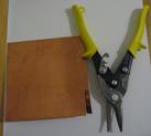
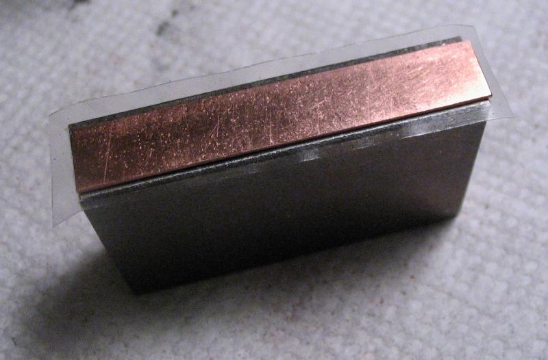
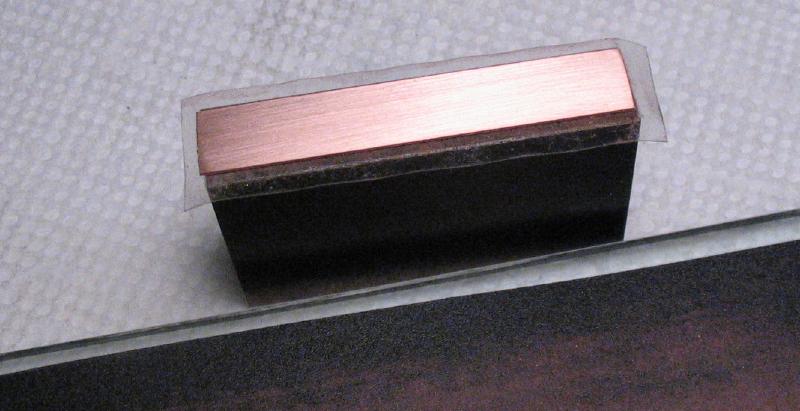
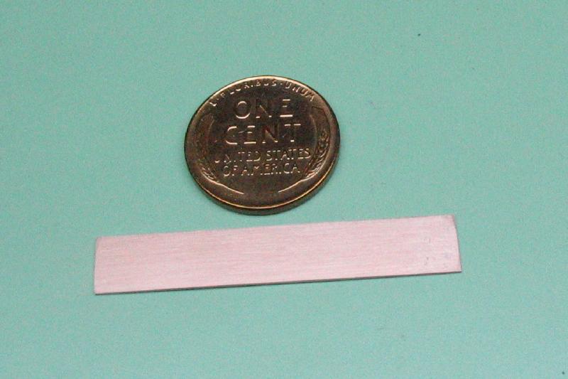
A copper lap was simply cut out from copper sheet. After struggling to cut some feeler gauge steel while building the telegraph key, a pair of aviation snips were acquired and used here to cut the copper sheet to it's rough shape. Sawing may be a better idea, but I was eager to cut something with the snips. The strip of copper was cut a few millimeters wide since the edge of the plate is rounded over from the supplier and the snipped edge is coarse, so both will need to be filed. The snips bend the work, but this was simply bent back by hand and hammered on the bench anvil with a piece of steel bar stock. The copper strip was attached to the milled flat edge of 3/8" steel bar with double-side tape. It could then be flattened and polished with emery paper on a glass plate.
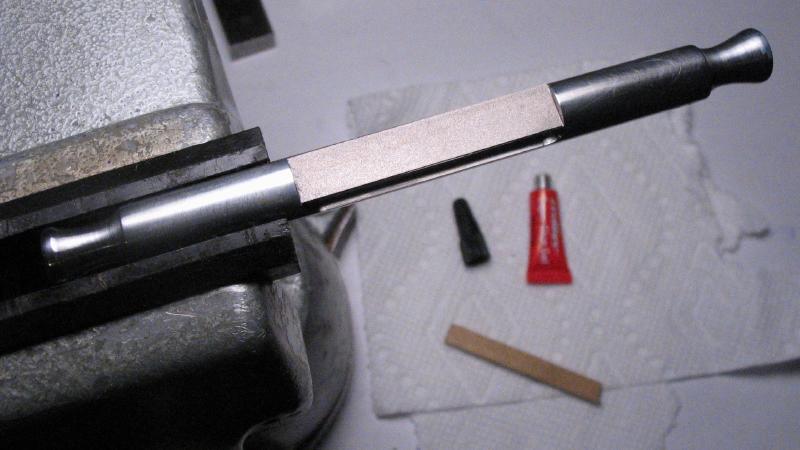
The length and width of the flat on the rod was measured and scribed onto the back of the abrasive shim. It was cut out using the snips above; the shim retained its shape fairly well and did not need any corrective bending as with the copper lap. The shim was squared up a little better with a needle file and fixed into place on the honing rod with "super" glue (a better adhesive may exist for this application, but this was on hand). The rod was held in a vise with soft jaws and a piece of wood was used to help square up the edge of the shim with the stepped side of the rod while gluing into place, however, the super glue hardens quickly! The extra shim that overhangs on the rounded side of the lap was filed off until the finished lap rod can pass through the guide tubes freely. I used an old, nearly dull file for this step since filing diamond abrasive seemed to be an excellent way to ruin a sharp file.
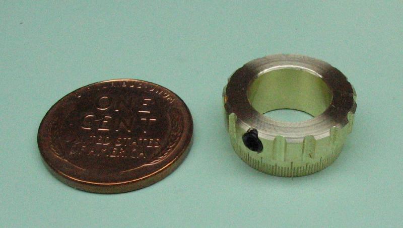
A graduated collar was made to provide a means of indexing the position of the tool holding mandrel. It was started from the scrap piece of 5/8" OD brass tubing sawed out above from the guide tubes. The end was faced and turned true for an excess length and then reduced to 14mm diameter for 3mm in length. The corner was chamfered 45 degrees and since the tool mandrel is closer to 3/8" in diameter, the 0.37" ID tubing was bored open slightly for a slip fit. The parting tool was then used to turn some clearance for the endmill in the next step.
The milling spindle was installed and aligned onto lathe center. First, a 2.5mm hole was drilled in the center of the larger diameter for tapping later on. A 1/16" ball end mill was then used to mill fifteen 0.5mm deep grooves using the headstock pulley indexing holes. I should have skipped the groove at the hole position, but this is minor. For engraving the graduations, an indexing plate was installed onto the headstock and the 120 count circle selected. An engraving bit was used to mill 120 grooves into the smaller diameter of the collar. These will be 3 degree graduations, which seemed to be the closest the marks could be made and still be readable. I made varying lengths for 3, 15, and 30 degree marks.
The work was parted off and mounted in a step collet to face the parted end and chamfer the corner 45 degrees to match the reverse side. The bore was lightly countersunk by hand to remove burs and the work mounted in a vise to finally tap the hole for the set screw. The collar simply slides onto the tool mandrel and can be locked into place where ever needed with its set screw.
The base was given a witness mark for reference when using the collar above.
The tool is essentially complete at this point and ready for trying out.
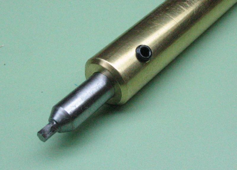
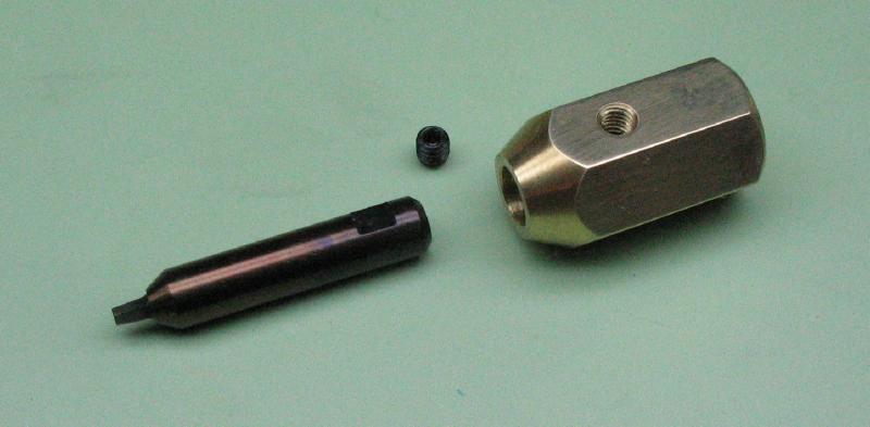
A hex key was made to keep together with the tool for adjusting the various set screws. The key was made from a short length of 5mm drill rod and piece of brass hex rod. The drill rod was mounted in a collet and faced and chamfered, and then a flat was milled near the end. The rod was reversed in the collet and the end turned down to about 2mm for a length of 3mm. This diameter was milled to a hex shape, about 1.7mm in width, by indexing the headstock through 60 degree steps and milling each face to the same depth.
This hex key was intended as an experiment for trying out the lapping tool. After machining, the work was fit to the tool mandrel and the hex portion finished to a 1.5mm width with the abrasive laps. The tool seemed to work fairly well, however, the resulting hex key has a slight taper to it, which will work fine in this case, but was not intended. This seemed to improve with practice. The lap rod tended to roll foward due the small width of the work, so some counter-rotation pressure was needed to maintain a flat stroke.
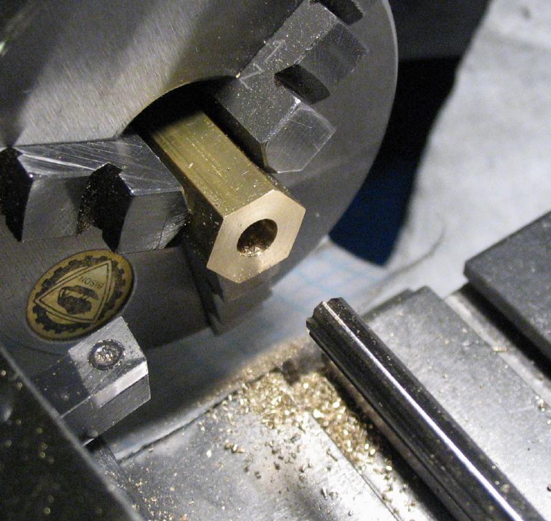
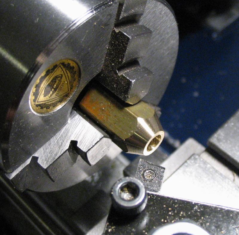
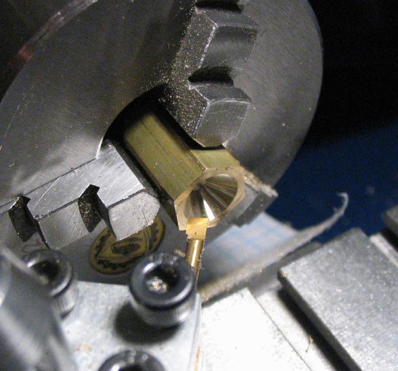
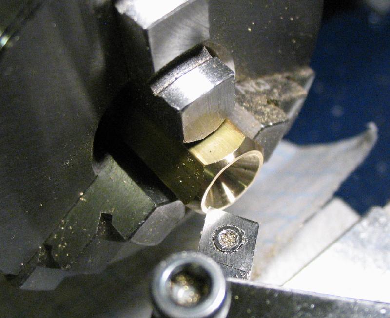
The brass hex rod was already drilled slightly on either end, left from a previous job, so it was faced on one end and drilled #19 and then reamed 5mm to depth of about 15mm. This end was chamfered generously and the work reversed in the chuck. Rather than facing this end to remove the drilled hole, it was bored to a taper to preserve as much of the overall length as I could. The rod was then drilled and tapped M3 for a set screw. I realized later that this will ironically require one to have a separate 1.5mm hex key to attach the set screw...
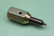
The hex bit was hardened and tempered and mounted in the handle.
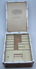
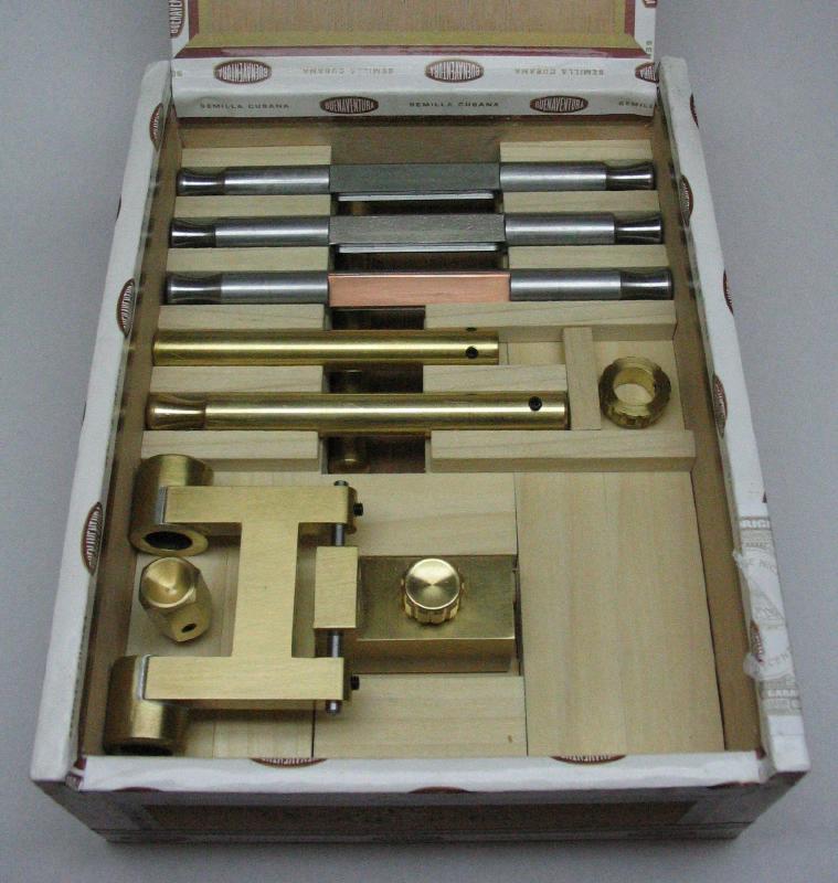
A storage container for the finished tool was constructed from a cigar box and some strips of wood glued into place to separate the various parts of the tool.
