
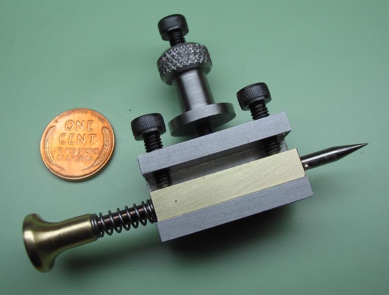
I am following the steps described in Daniels "Watchmaking" for plotting an equation of time cam, although going about it in a slightly different manner. I am created a couple devices that mount on the lathe to assist in laying out the grid lines on which the cam can be plotted. The cam rotates once a year and the varying radius corresponds with the variation between true and mean solar time. Setups are needed for scribing circles for the range of minutes (+17 to -15) and arcs for days of the year. A toolpost-mounted scribe was made for marking the minute circles and a fixed radius scribe was made for marking the day arcs. A pair of face plate clamps to hold the work were needed as well and are described on another page.
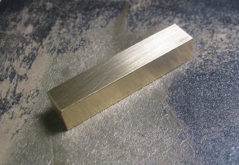
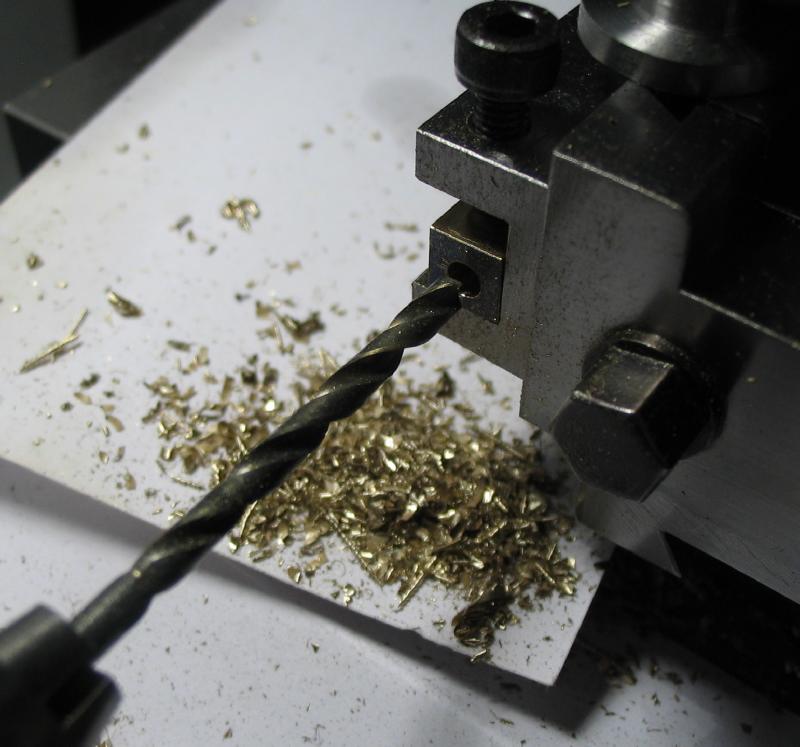
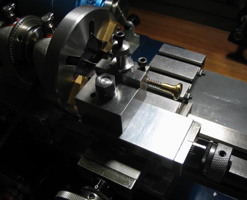
A scribing device that fits the tool post was started from a length of 1/4" brass square rod that was cut to fit a quick change tool-holder. It was mounted and centered in the holder and drilled and reamed to fit a length of 1/8" drill rod. A small mark was made to recall the orientation in the tool holder.
|
|
|
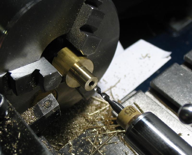
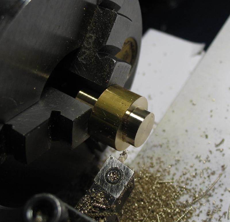
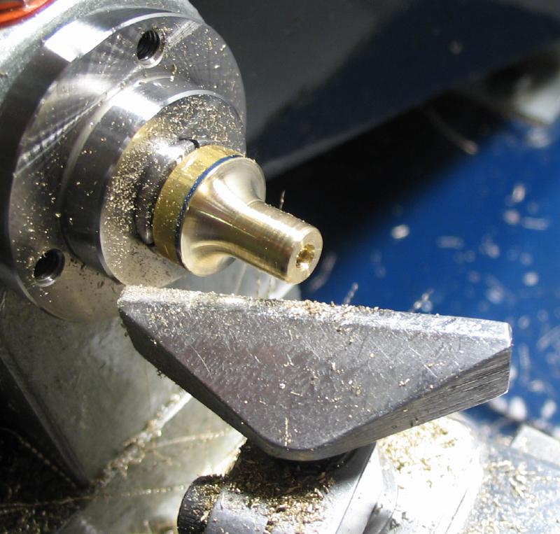
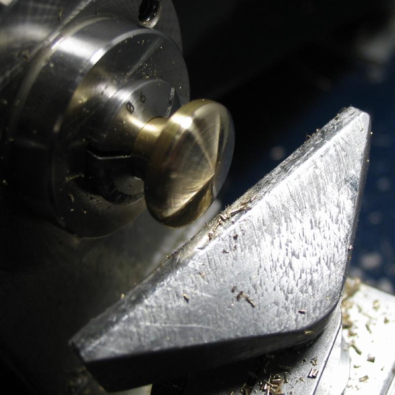
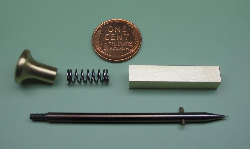
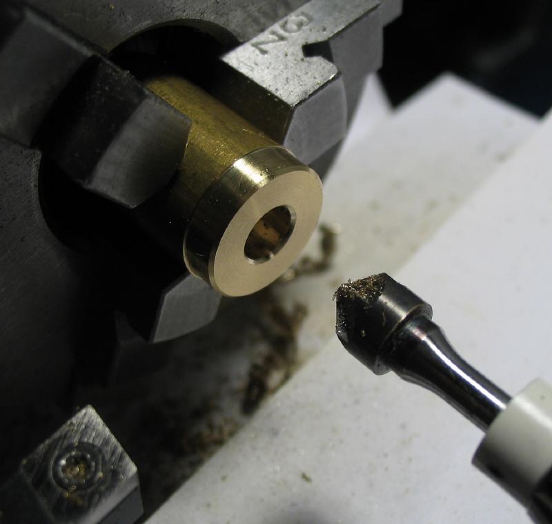
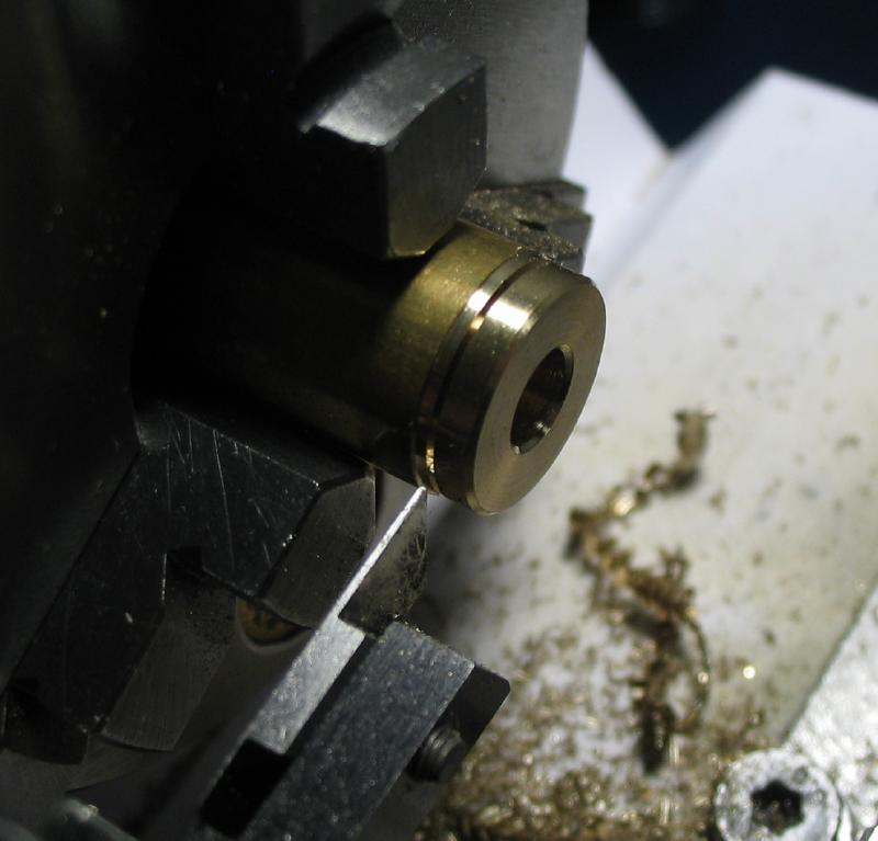
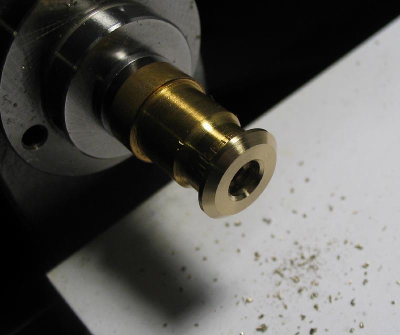
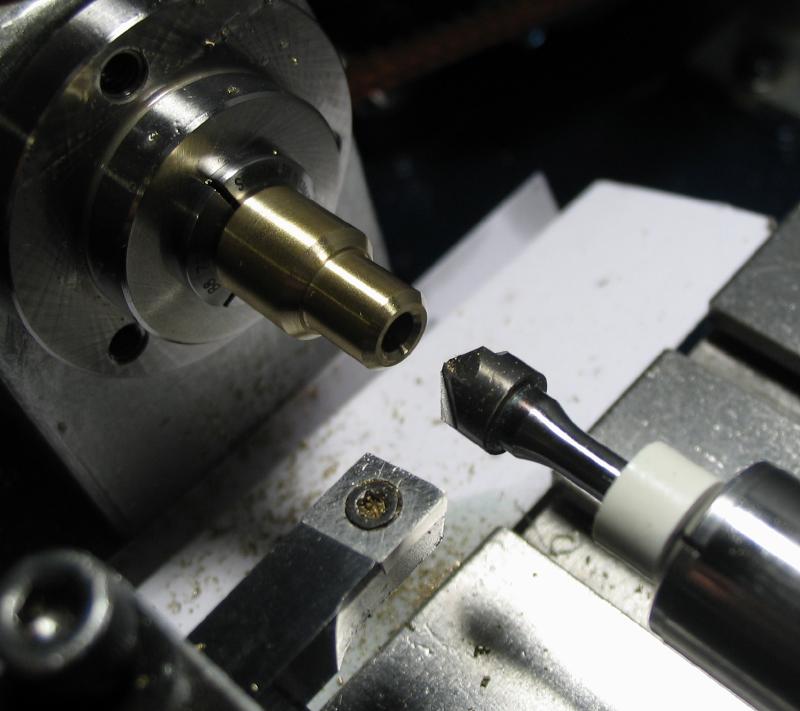
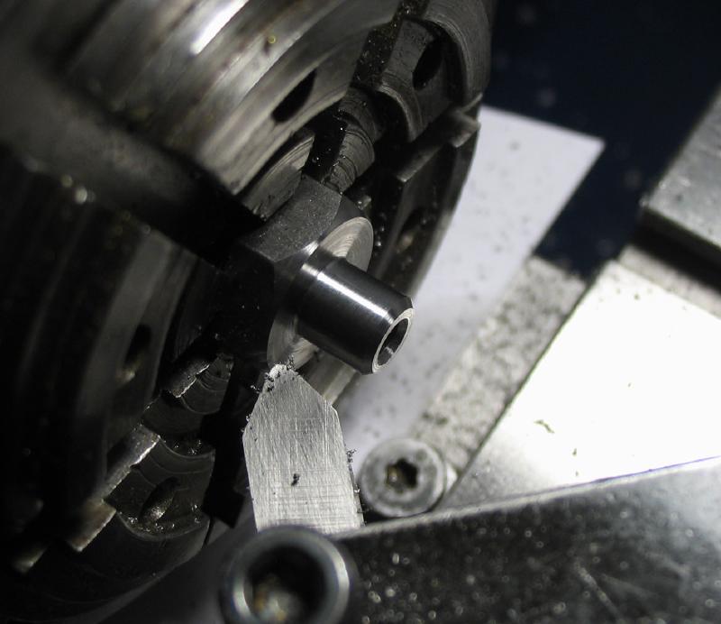
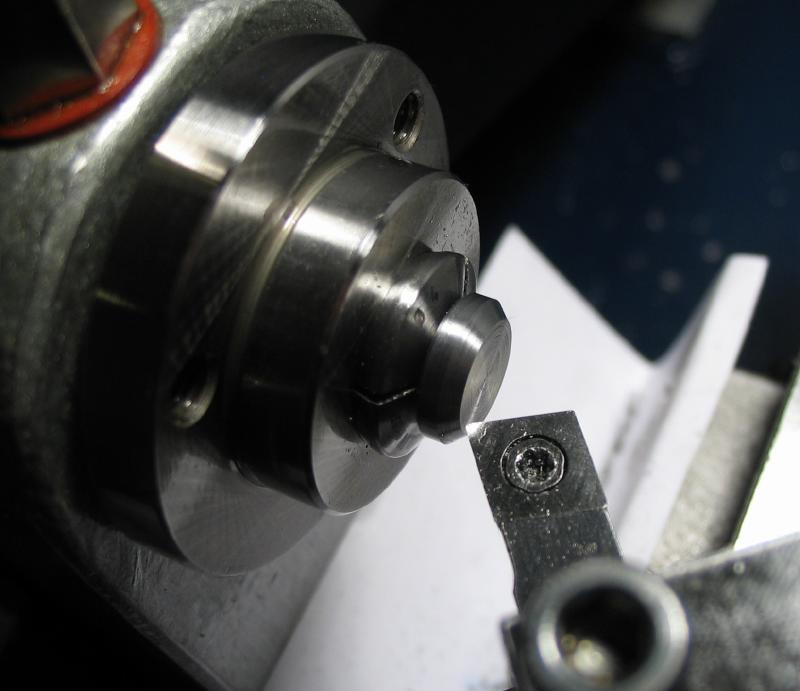
A thumb piece was made from a short length of brass rod. The end turned down to about 1/4", drilled and tapped M2.5, and then reversed to turn a short length to 8mm. The 8mm end was held in a collet and a curved transition turned with a graver made from 1/8" drill rod. The work reversed again and the 8mm boss turned off and the remaining face rounded over.
|
|
|
|
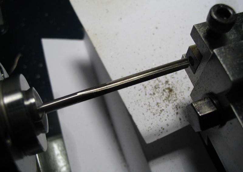
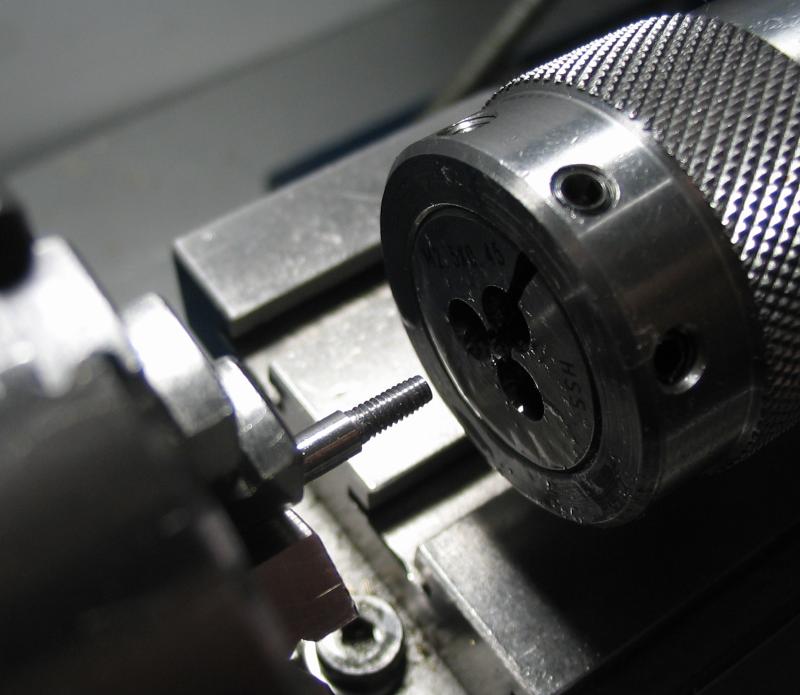
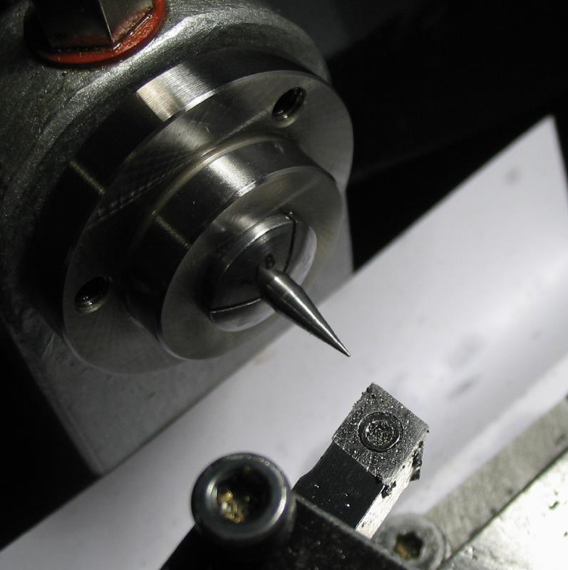
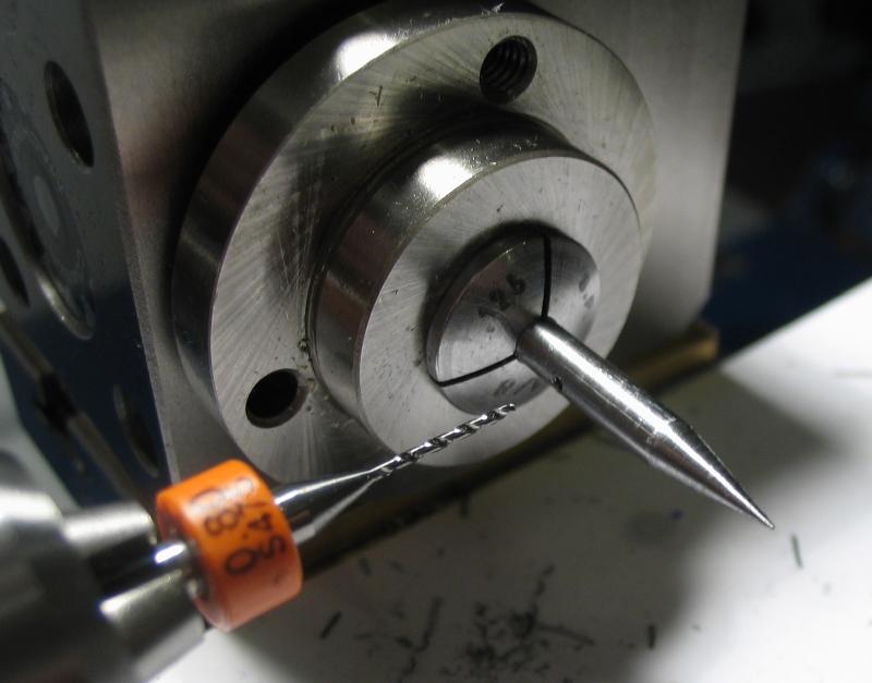
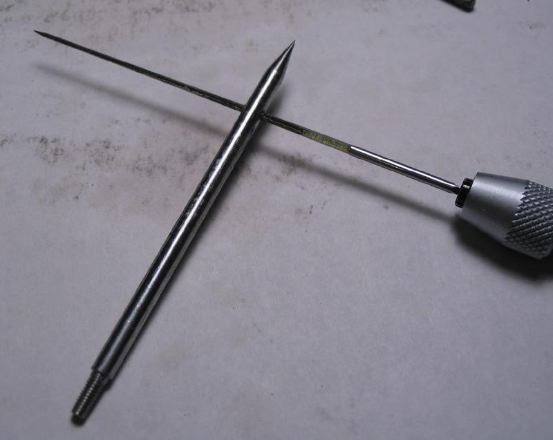
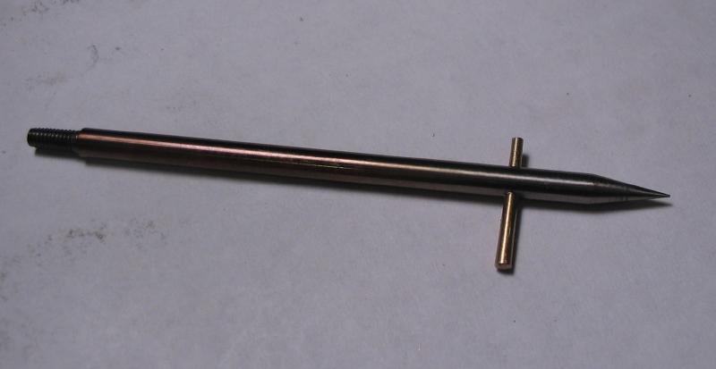
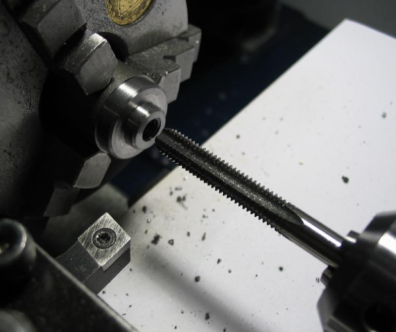
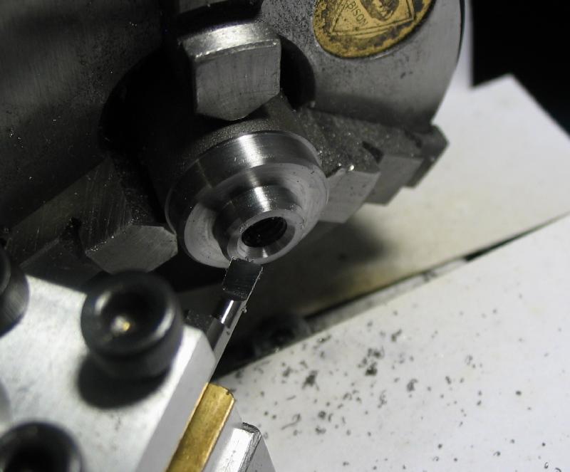
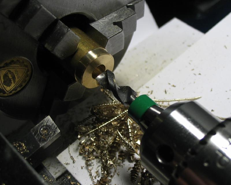
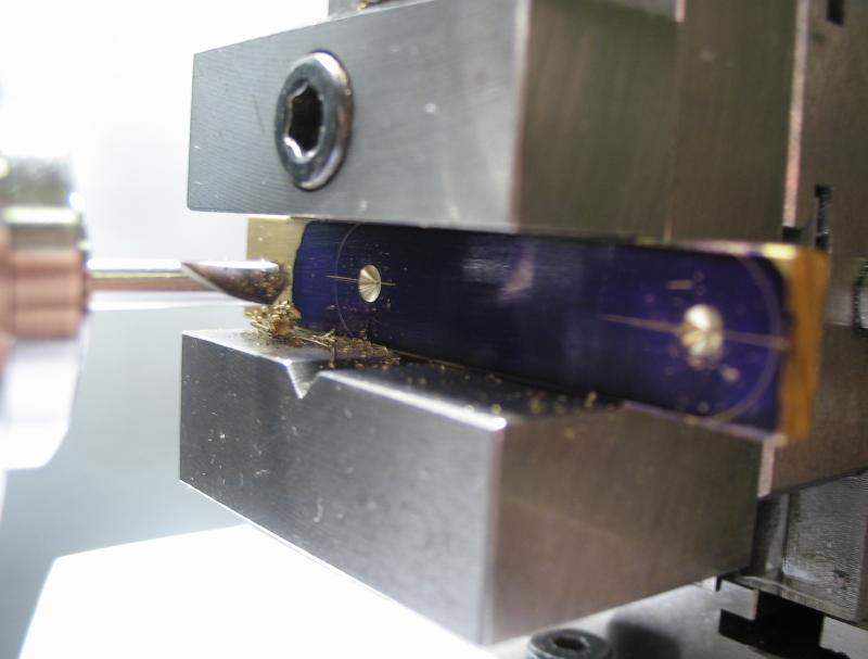
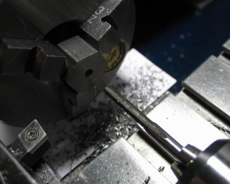
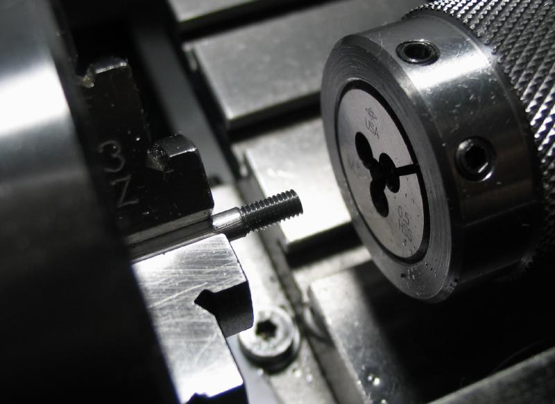
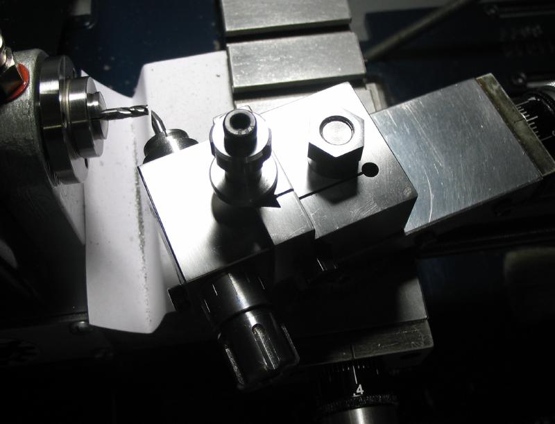
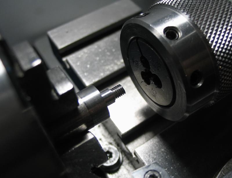
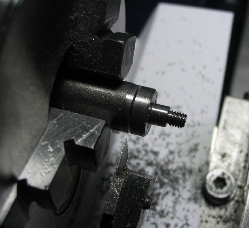
The scribe was made from 1/8" O1 drill rod. One end was turned and threaded M2.5 to fit the thumb piece. The rod was reversed into a collet and the other end turned with a 10 degree taper to form a point. The work was tried in the holder and the location for a stop pin found. It was moved to the dividing head and the location cross drilled 0.8mm. The hole was broached to fit a brass taper pin (it is the cut off tip of a pin from another task).
|
|
|
|
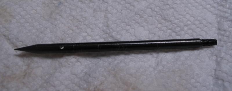
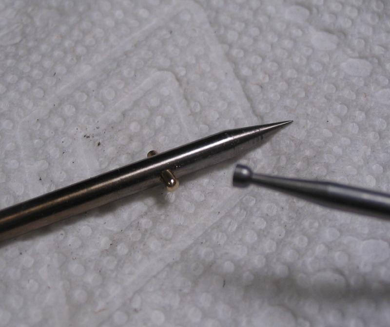
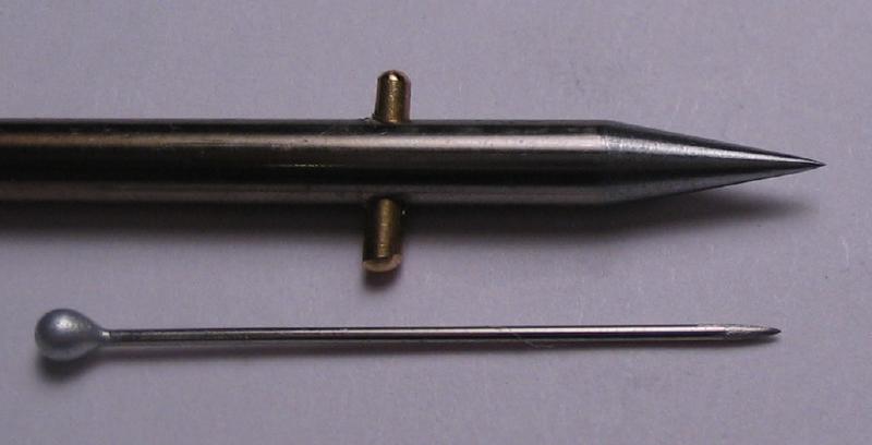
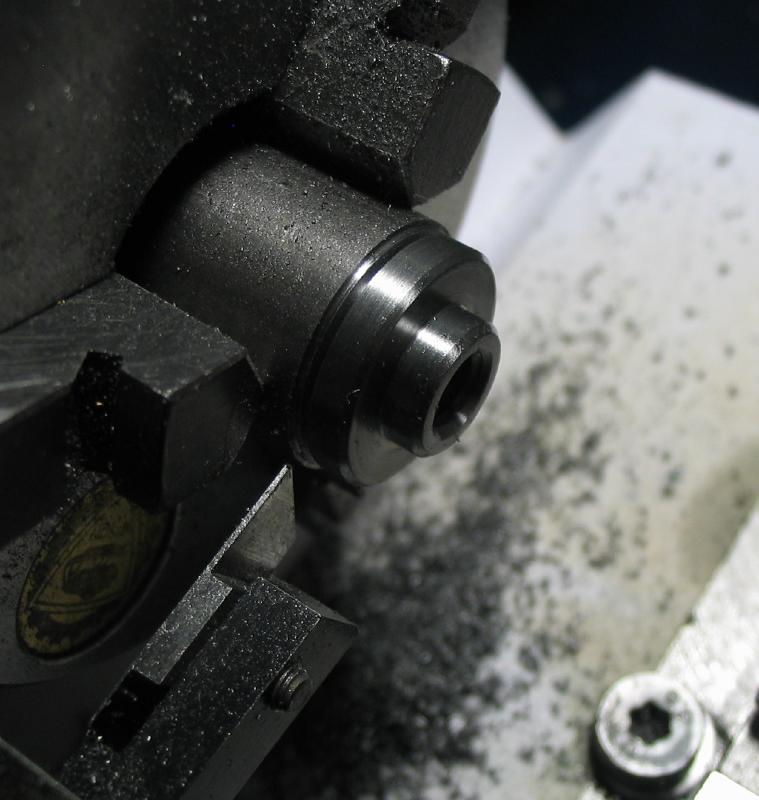
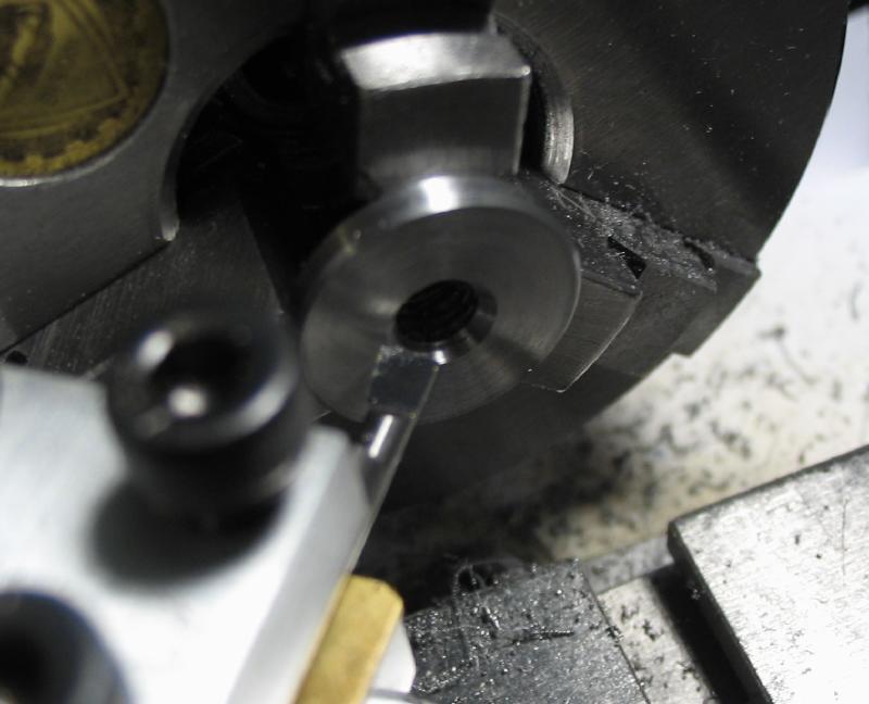
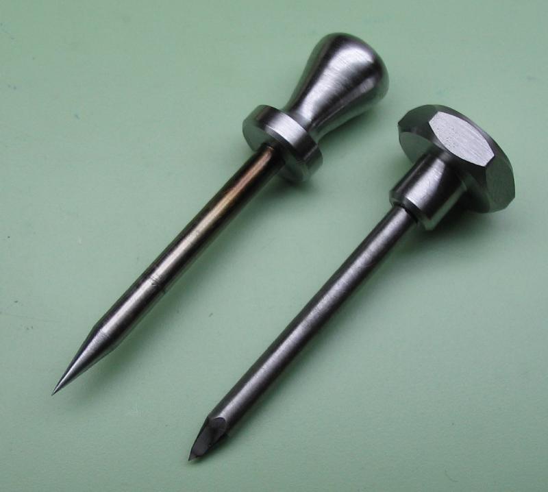
The scribe was hardened and tempered, hopefully leaving a sharp and durable point. The brass pin was hammered into the broached hole, sawed off and rounded over. The rightmost photo was taken later after the point was sharpened with diamond hones.
|
|
|
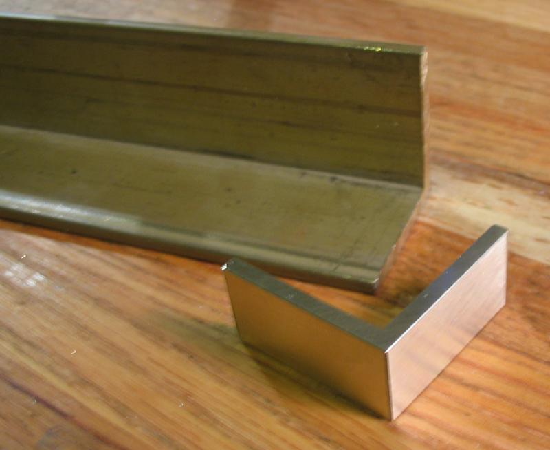
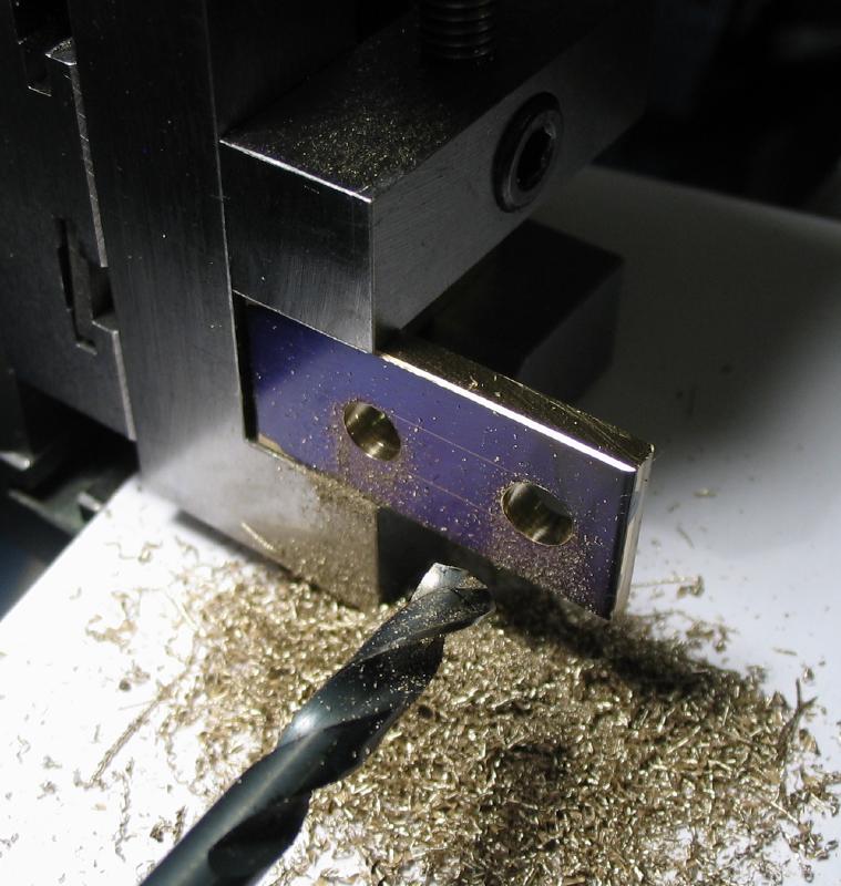
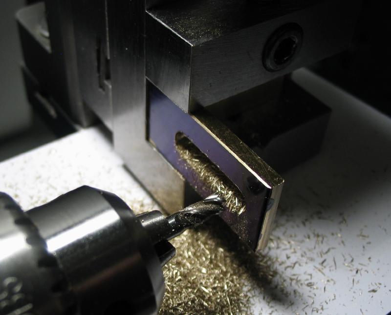
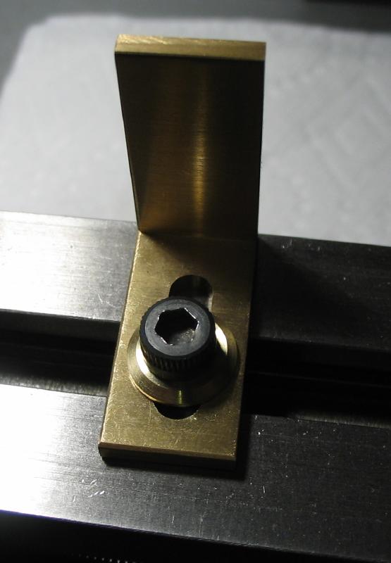
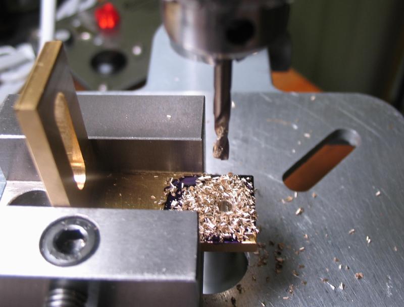
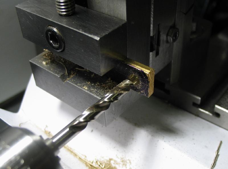
A bracket that can be attached to the lathe bed was made from a short section of L-shaped brass bar. To allow for some adjustment of position, a slot was formed by drilling 5mm and connecting the holes by milling.
|
|
|
A T-nut to fit the lathe bed was made from 5/8" cold roll steel rod. The dimensions were modeled after a standard T-nut.
|
|
|
|
A washer was made from brass rod. In the last photo it is being held on a cement chuck since it had been chamfered a little too excessively to allow it to be gripped in a step collet.
|
|
|
|
|
|
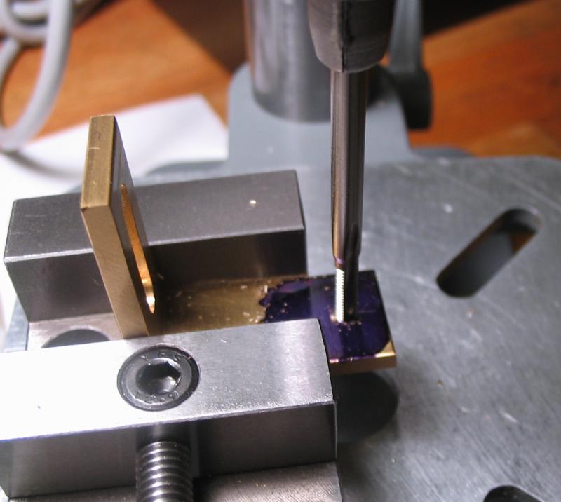
The bracket was drilled and tapped M3 for attaching the arm.
|
|
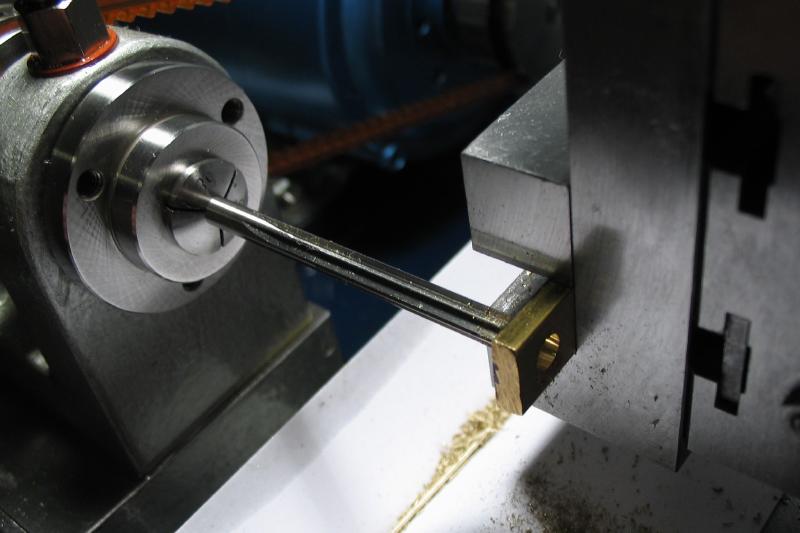
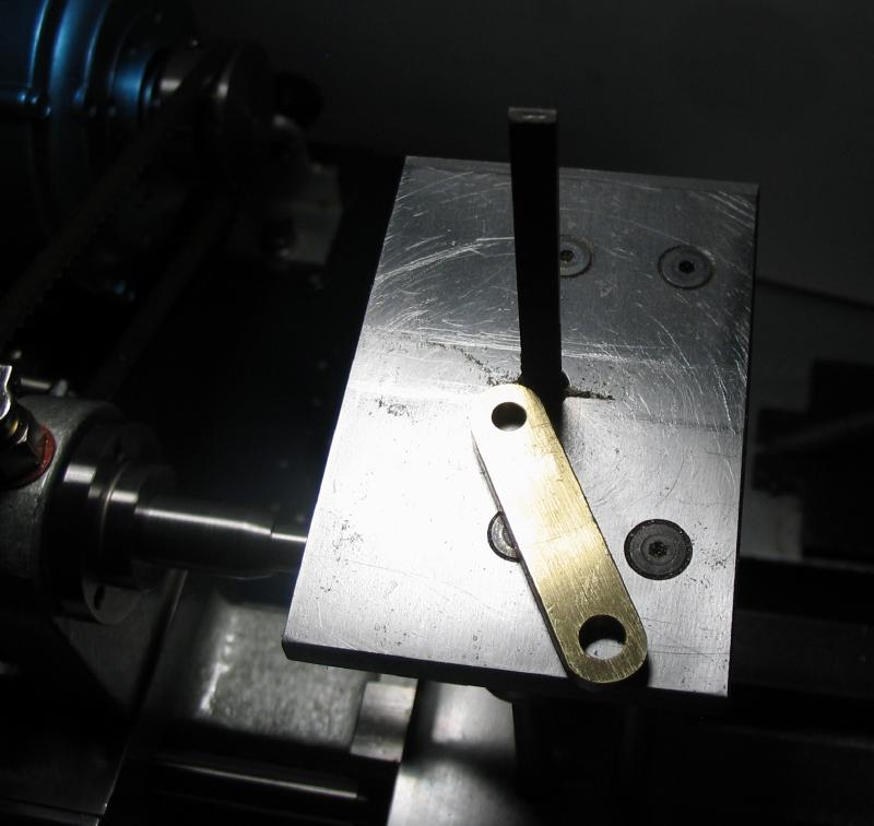
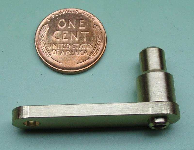
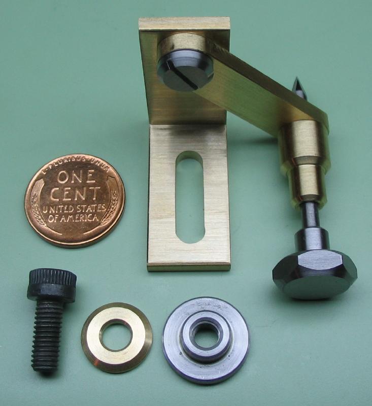
The pivoting arm was made from 1/8" x 3/8" brass bar. I had to decide what the radius will be, and concluded on 30mm - this will match the radius of the cam follower. I used the cross slide to measure the distance between spot drilling. One position was drilled and reamed 4mm and the other 5mm. The corners were removed rounded over with the filing machine.
|
|
|
|
A sleeve for holding the scribe was turned from a short length of 3/8" brass rod. It was turned to slightly over 5mm (about 5.02mm) to friction fit the hole in the arm, and drilled and reamed 1/8". It was reversed into a collet for turning the other end for cosmetic purposes.

|
|
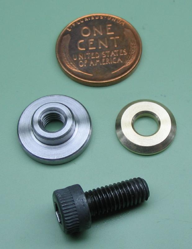
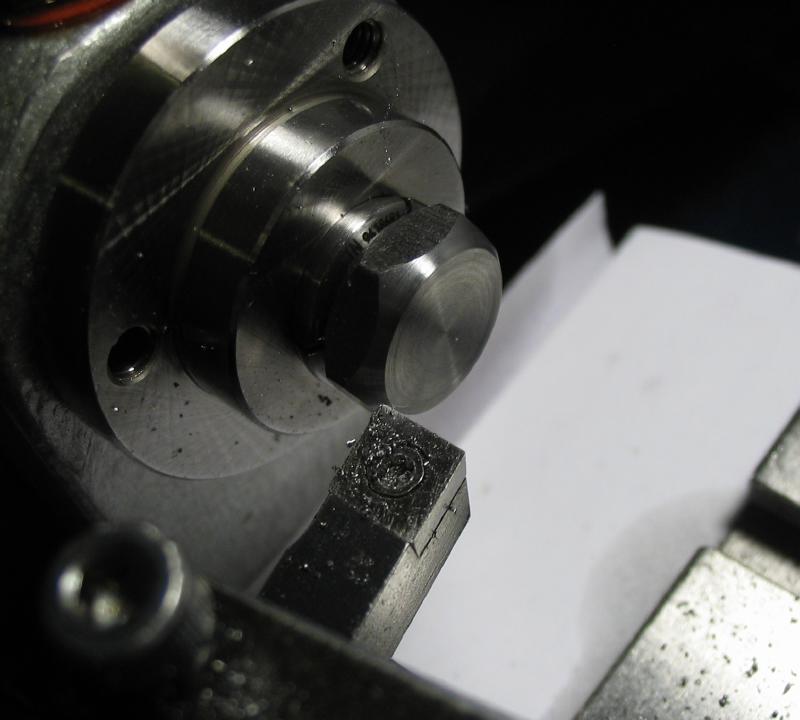
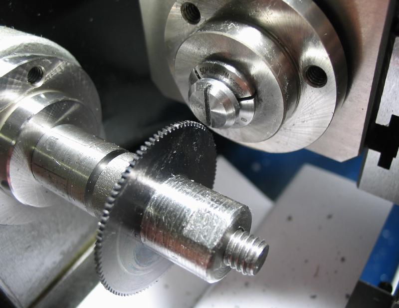
A knob for the scribe was made from a short piece of 1/2" hex steel (12L14). It was drilled and tapped M3x0.5 and a short length reduced to about 6mm diameter. The corners were relieved 45 degrees. Finally, the reverse end was faced and and chamfered. The rough faces of the hex were simply cleaned up on emery paper.
|
|
|
|
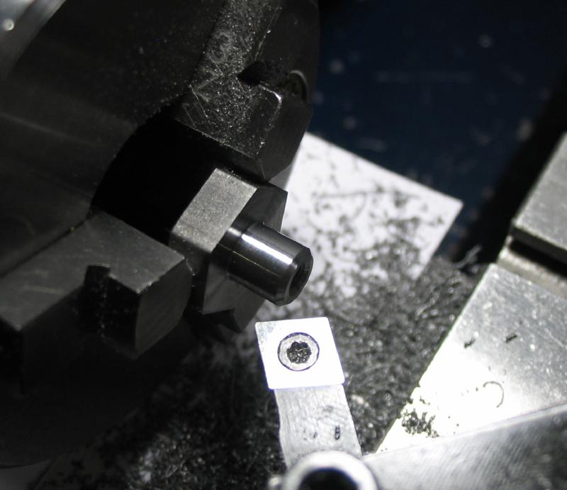
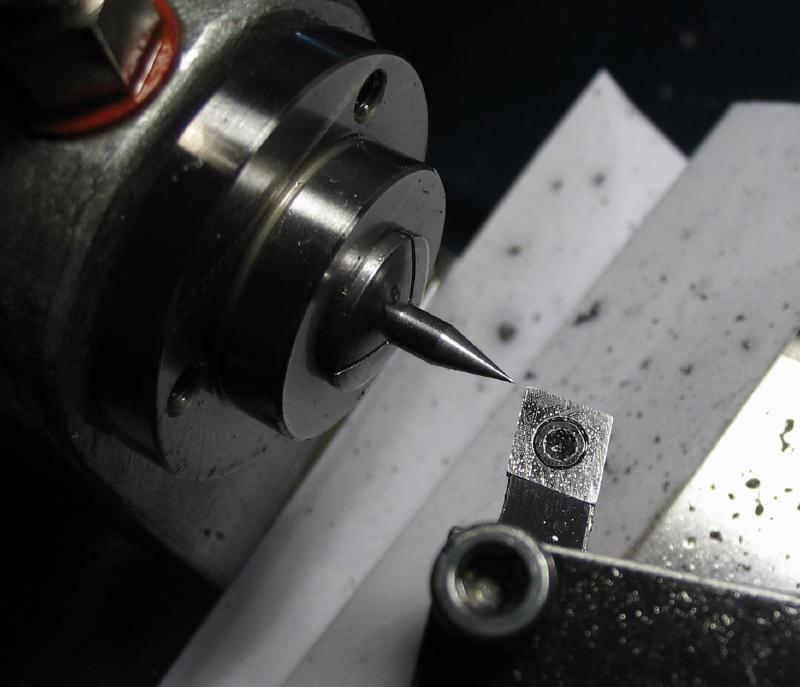
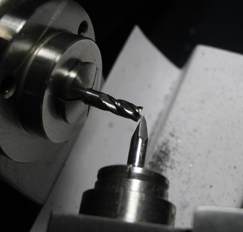
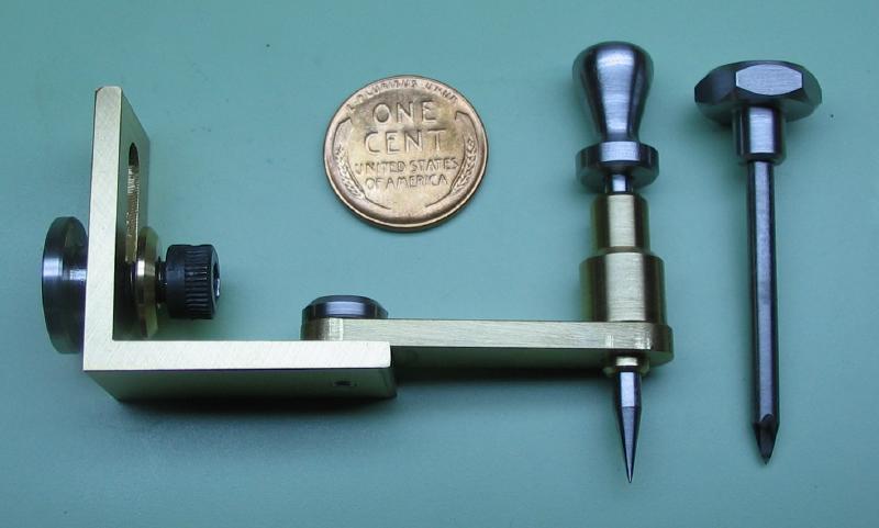
A scribing center was made from 1/8" drill rod. It is intended for marking point locations, so was designed as a small chamfering point. One end was threaded to fit the knob made above, and the other end turned to a point, which is a 15 degree taper. The work was mounted in the collet holding tool post, centered and the top slide left at the same angle used to turn the taper. An endmill was used to form a three faced point, being careful to mill each face to the same depth. The faces were sharpen with a grinding stone on the lathe. The bit was heat treated for use.
|
|
|
|

|
A similar scribe was made with a 20 degree point. It has a grip that is a little more elaborate, and was turned by hand from a short length of 3/8" steel rod that was also tapped to fit the threaded end of the drill rod.
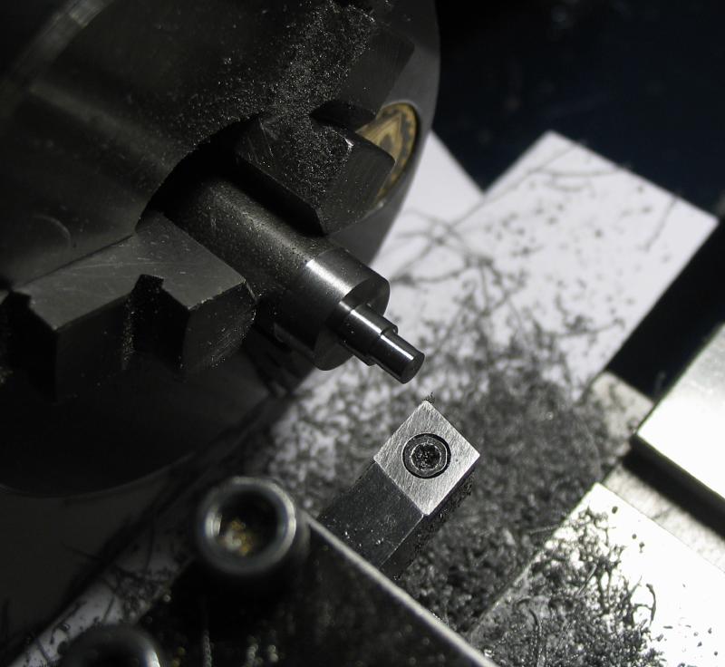
A shoulder screw was made that will retain and act as the pivot for the scribing arm. It was made from 3/8" diameter cold roll steel (12L14). It was turned for 1/8" to thread M3x0.5 and for slightly over 1/8" to fit the reamed hole in the arm. It was then parted off, the reverse face turned and then slotted with a 0.8mm saw.
|
|
|
|
|
|
|
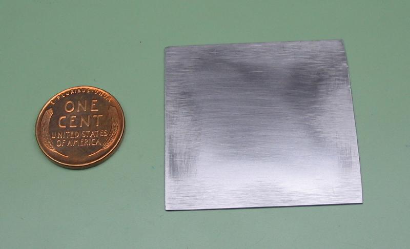
The cam was started from a roughly 1.5" length of 1/64" x 1.5" oil hardening steel. The surfaces were cleaned up on emery paper, although there was a slight bow in the steel which proved difficult to remove.

|
|
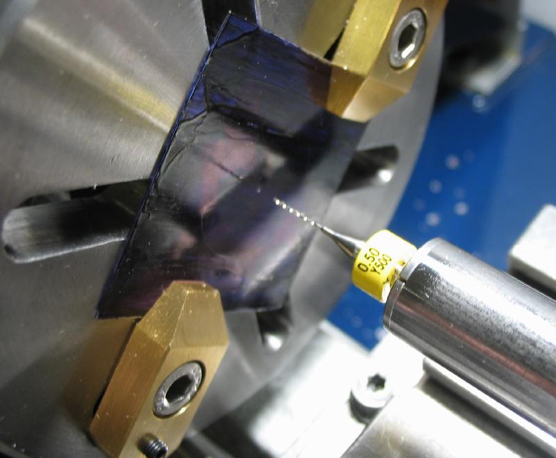
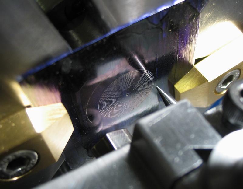
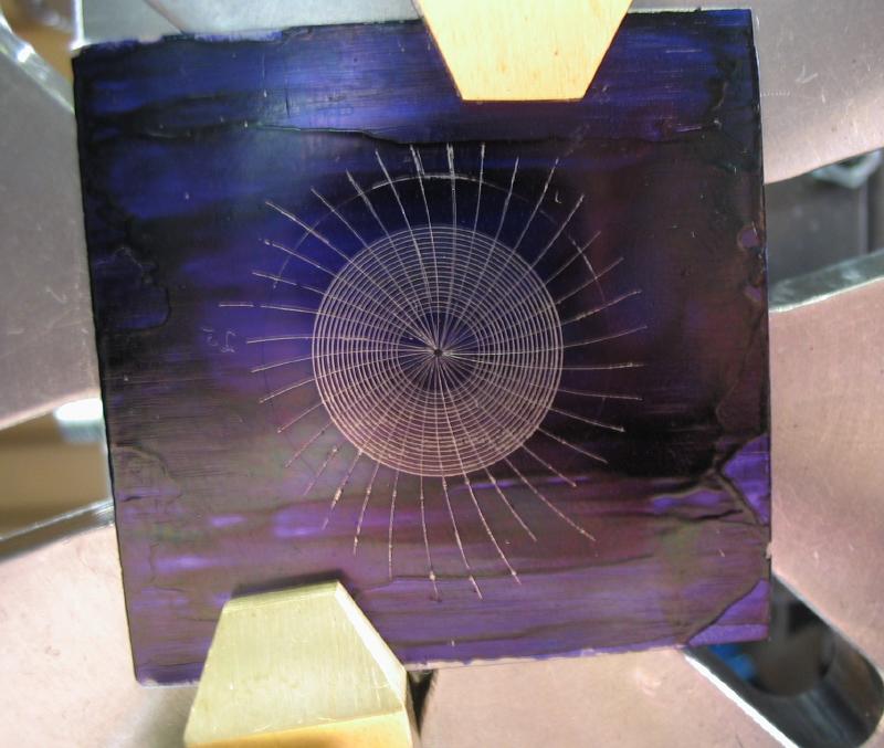
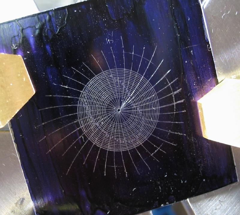
A face was coated with blue layout fluid and roughly centered on the lathe faceplate and secured with clamps. A center hole was drilled 0.5mm, and the toolpost scribe installed and centered in the hole. The cross slide was used to advance the scribe for marking circles of two minute graduations (0.28mm) with the zero circle at 5mm radius.
|
|
|
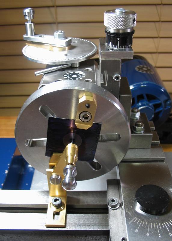
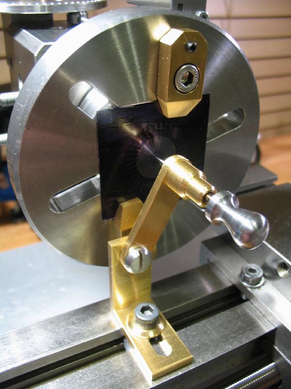
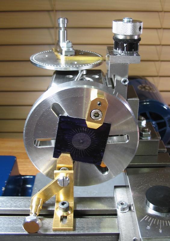
The faceplate was moved to the dividing head, which was equipped with the custom 73 position dividing plate and sector device that enables indexing by days of the year. The bracket with 30mm radius pivoted arm was attached to the lathe bed and centered with the hole in the steel plate. Arcs were scribed onto the face of the plate, advancing the dividing head to mark the 2nd, 12th, and 22nd of each month. This is mostly steps of 10 days except between months where it varies from 9 to 11 days. Converting to dividing head units requires a calculation, e.g. 9 days is 72/73rd of a turn of the detent arm; 10 days is 1 and 7/73 turns, and 11 days is 1 and 15/73, so it can be easy to loose track (there are a couple false starts where I was off by a 'day').
After scribing the arcs for roughly 10 ten periods, I then decided to go back around, indexing to a couple intervening days between arcs and use the chamfering point to plot and mark the perimeter of the cam on the grid. This did not work as well as I hoped, but an general outline of the desired shape is there.
|
|
|
|
|
