A depthing tool for unmounted clock wheels and pinions is described below. Construction plans and descriptions for similar tools are provided in many publications, including those by John Wilding ("Tools for the clockmaker") and William Smith. Smith provides details for two versions, first in "How to make a Grasshopper Skeleton Clock" and a refined version in "Clockmaking and modelmaking tools and techniques" and is the design followed here. Mr. Smith notes that the tool is described in F.J. Britten's "The watch and clockmaker's Handbook," which dates to over 100 years ago and even then still had a citation to the "late Mr. Gray." The device is intended for unmounted wheels and pinions (i.e., not mounted on arbors). Overall, it is fairly simple, consisting of a slotted plate with two adjustable carriers to which a wheel and pinion pair are mounted and their proper working distance determined by trial. The carriers can be moved and locked into place with large thumb nuts and a screw feed is provided for making fine adjustments. The mountings (i.e., runners) for the wheel and pinion also act as the center and scribe for transferring the distance to the clock plate. The runners are made from drill rod stock and can be machined to suit the work at hand.
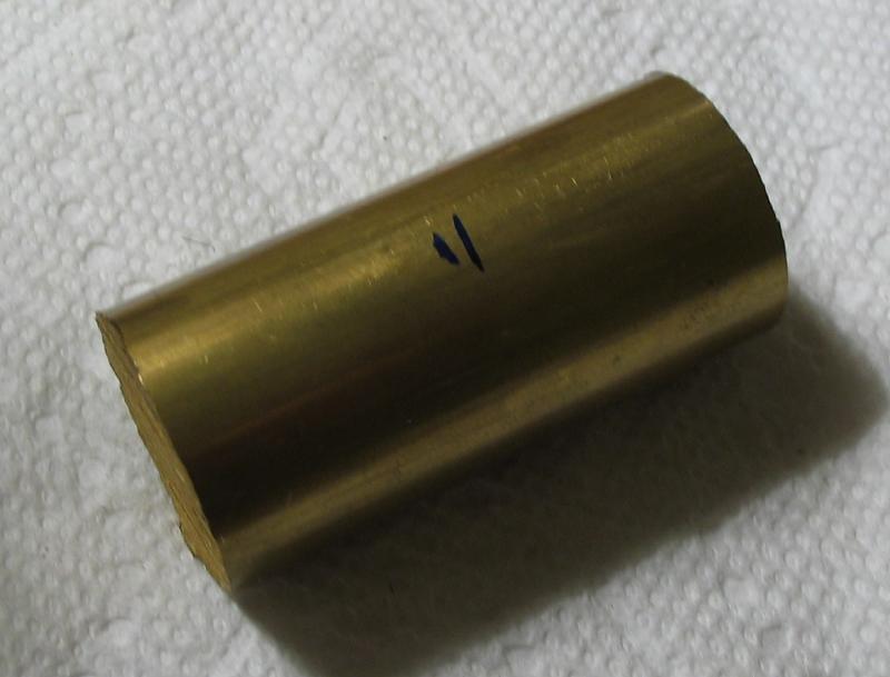
The work was started with the carriers and their locking nuts. They were all made from 1" diameter brass, although 7/8" would be closer to final diameter. I had 1 and 2 inch lengths in the stock bin, so one carrier was made from the 1" piece and the 2" piece used to start the two nuts and the remainder used to make another carrier.
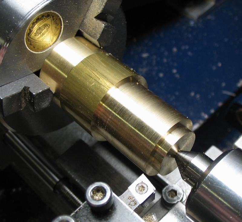
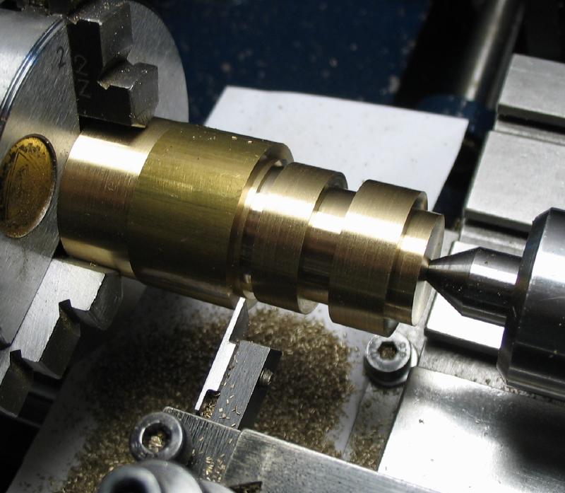
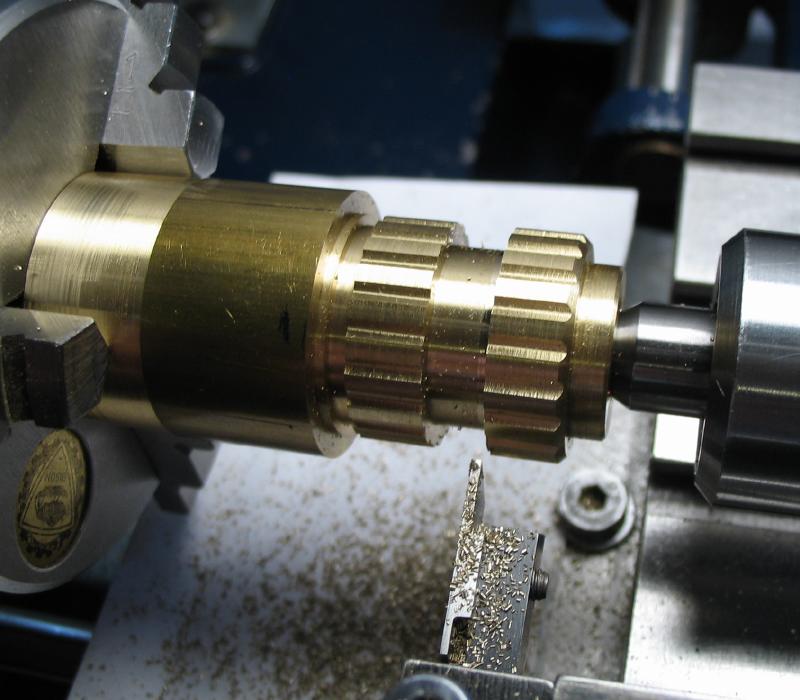
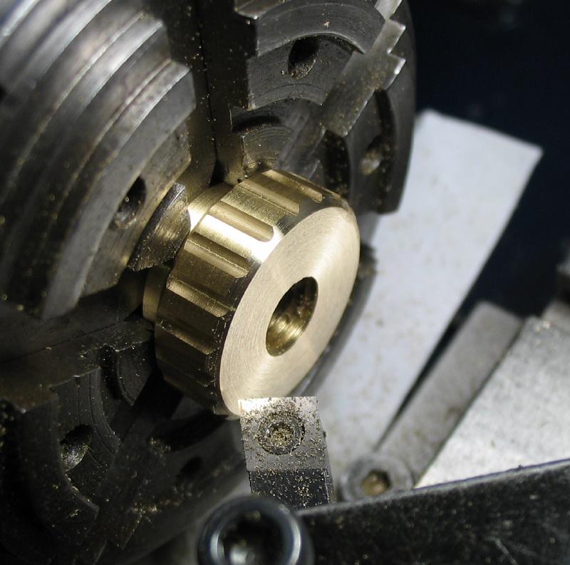
The rod was turned and faced to provide a true surface and this end reversed in the chuck. The thumb nuts were turned to shape and the parting tool used to form the waisted sections. A ball endmill was used to form 20 grooves in lieu of knurling and both nuts were milled at the same time.
The rod was turned and faced to provide a true surface and this end reversed in the chuck. The thumb nuts were turned to shape and the parting tool used to form the waisted sections. A ball endmill was used to form 20 grooves in lieu of knurling and both nuts were milled at the same time.
|
|
|
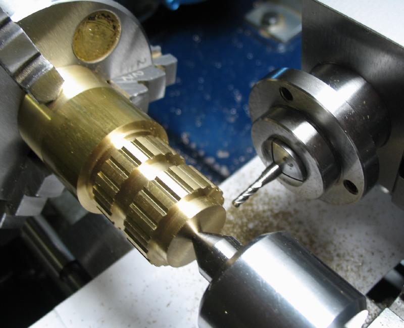
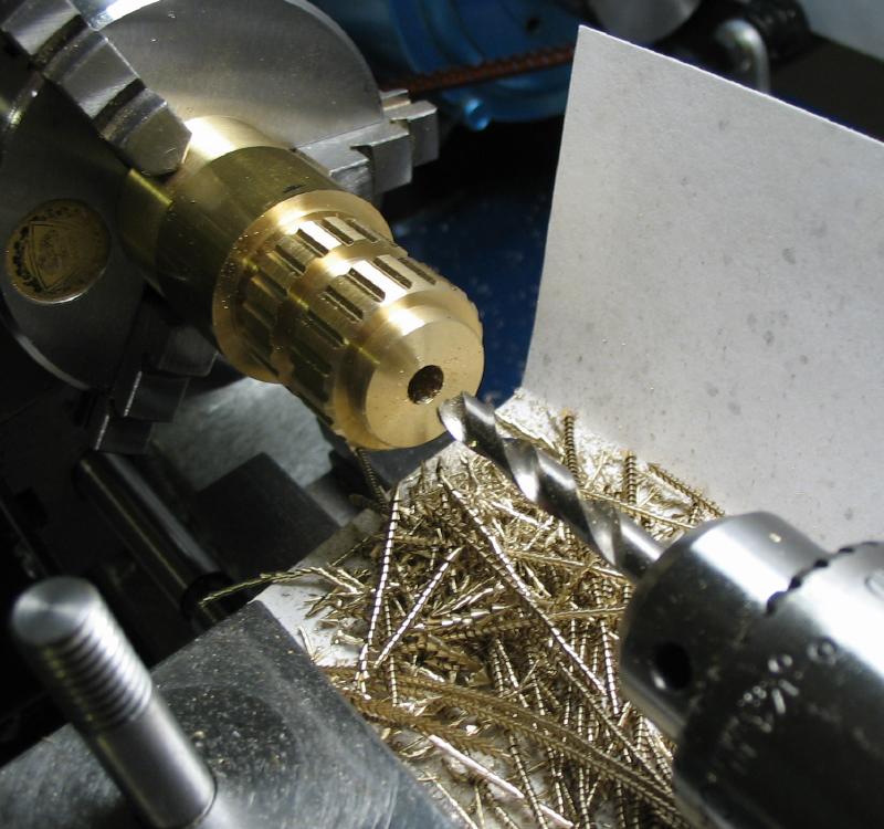
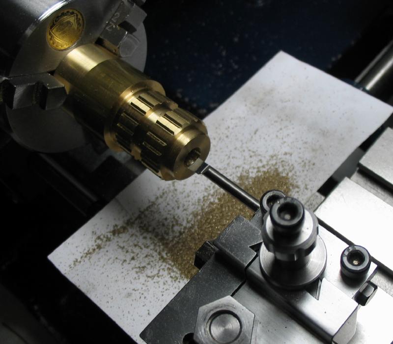
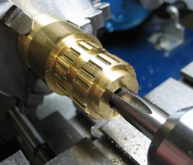
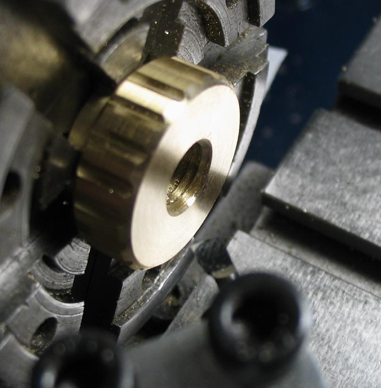
The corners were chamfered and the work was drilled and had to be bored since the correct drill bit was not on hand, and then tapped 5/16"-24. The hole was countersunk and the first nut parted off. The second nut was given a similar finish and parted off as well. The parted faces were then turned and the corners relieved. I used the 6-jaw chuck to hold the parted work, although the 3-jaw would have likely done just as well.
|
|
|
|
|
|
|
|

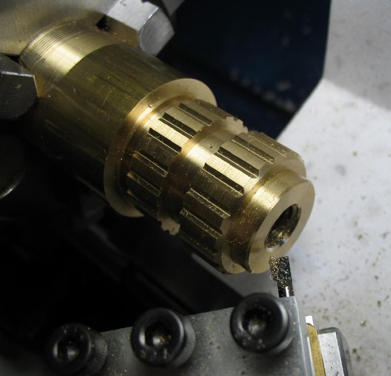
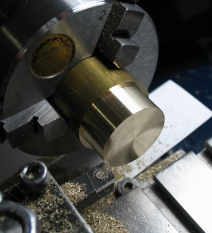
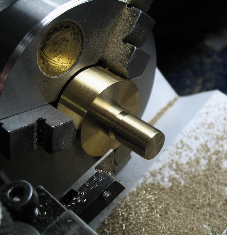
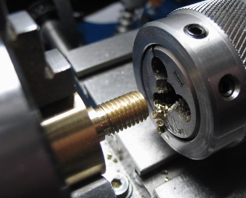
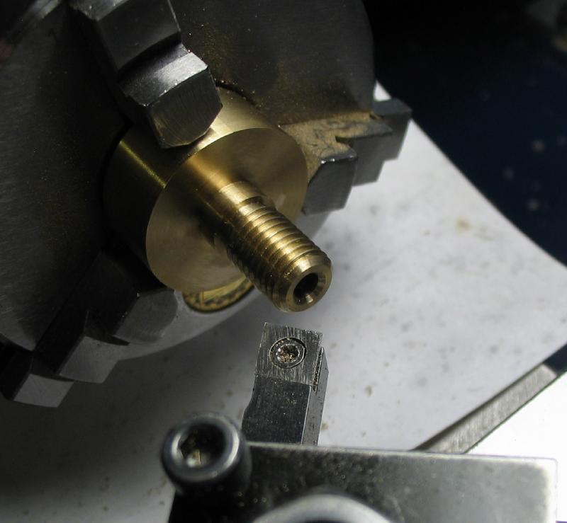
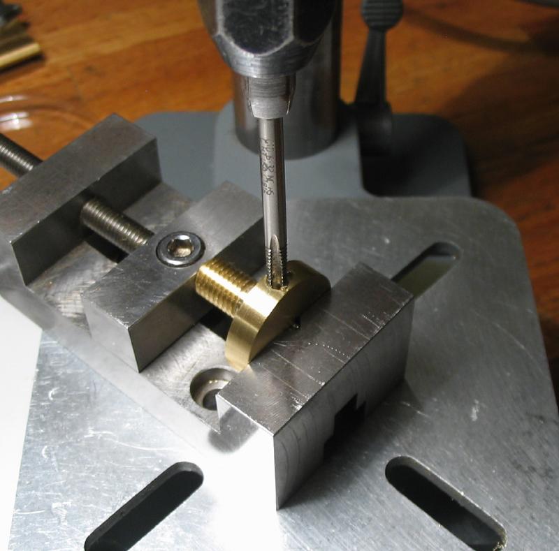
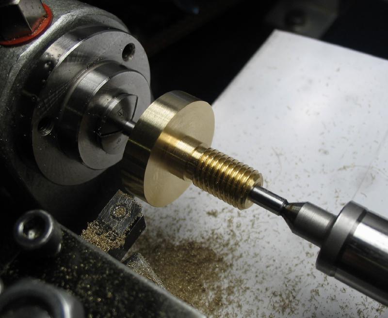
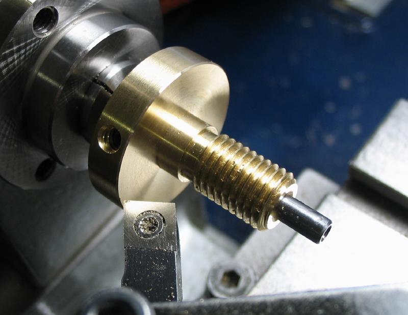
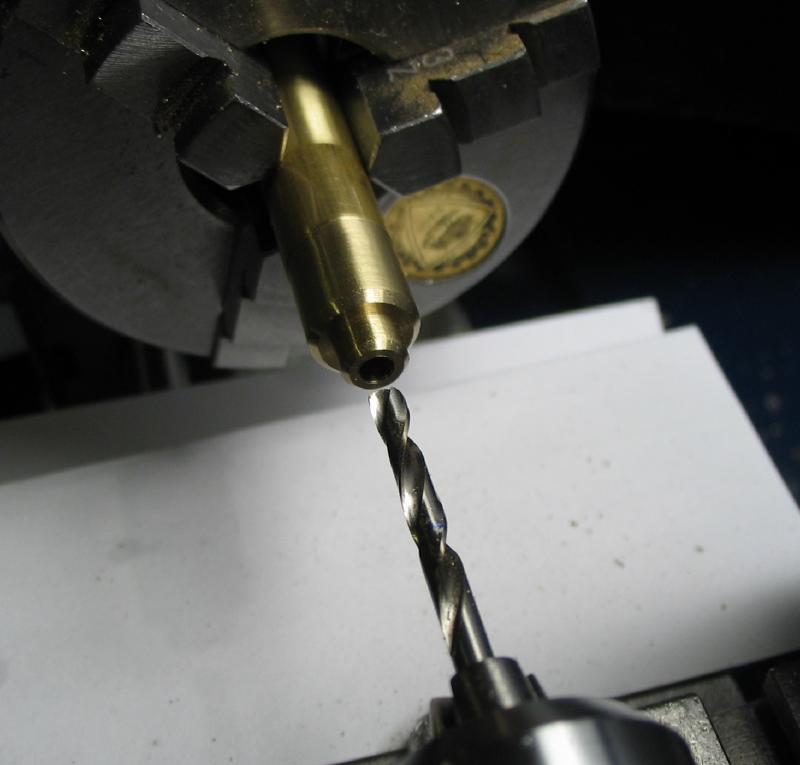
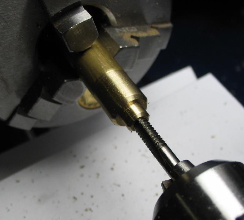
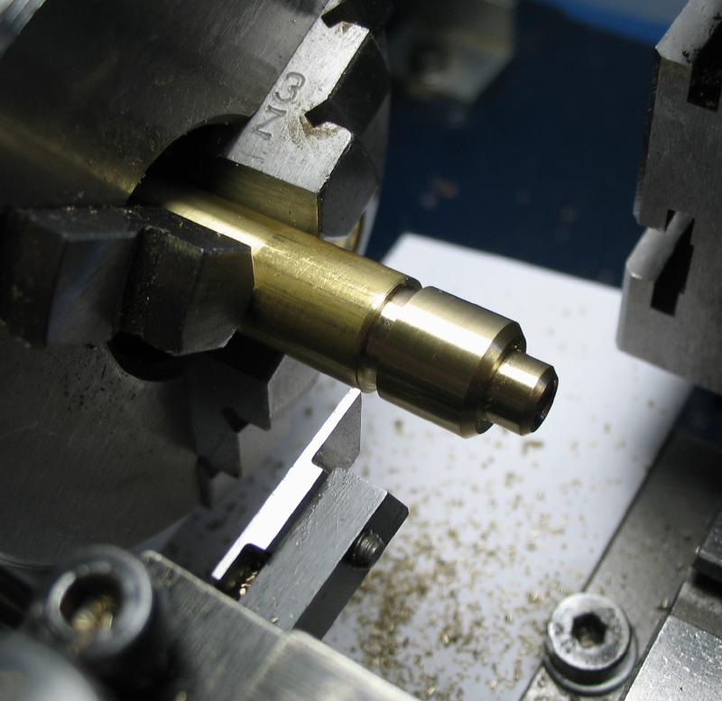
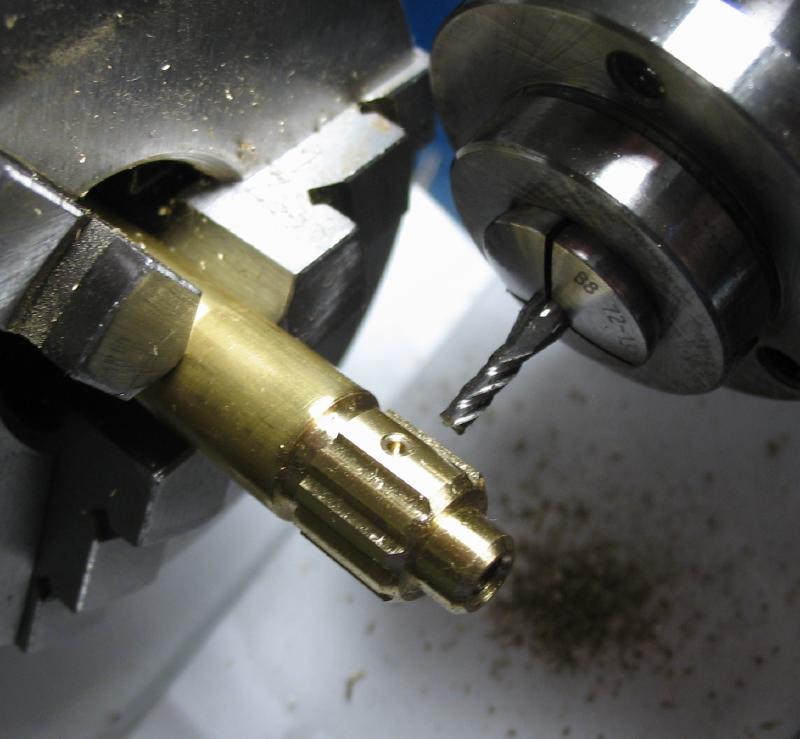
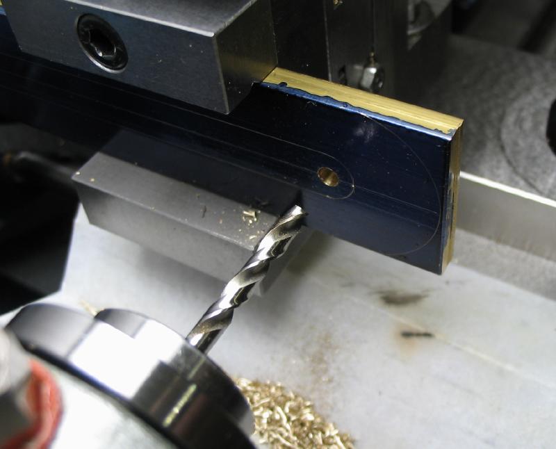
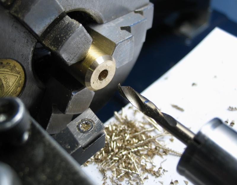
The carriers are made from roughly 1 inch lengths of 1 inch diameter brass. The length is longer than necessary, but the added length provides a more sure grip in the chuck, which is likely helpful while threading. The 5/16"-24 tap and die are a bit large for using on a small lathe, and single point threading would be preferred if available. Like above, a freshly turned portion was held in the chuck and can be helpful should the work need to be re-chucked, since there's a better chance of getting it running true again. The reverse end was turned but all dimensions left oversize for now, except for the portion to be threaded. It was drilled and reamed to fit the runners, and then threaded. Corners were chamfered and holes countersunk, and the work reversed again to reduce the head portion to almost the correct thickness and the position for the set screw drilled and tapped.
|
|
|
|
|
|
|
|
|
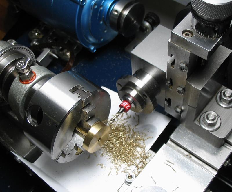
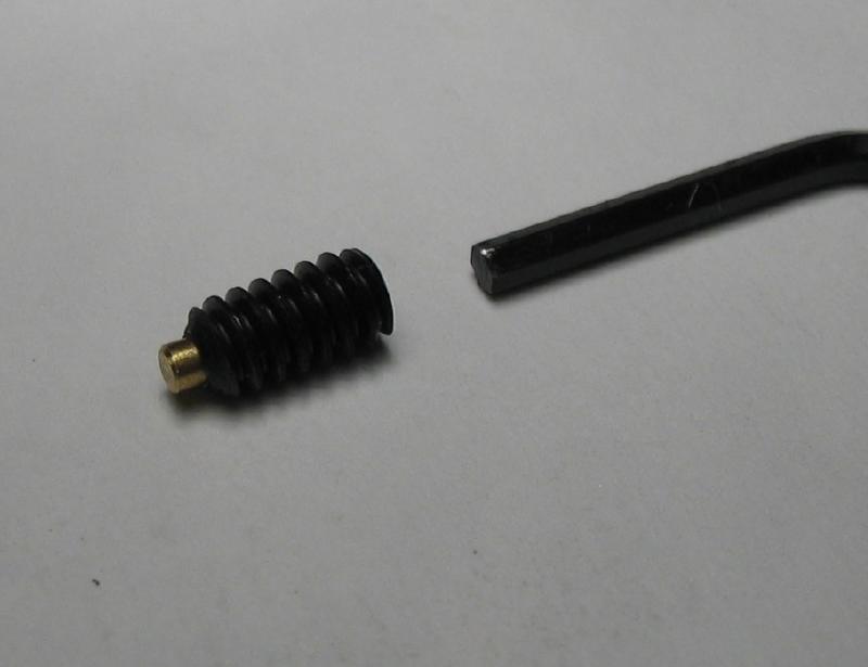
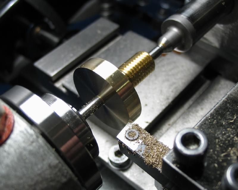
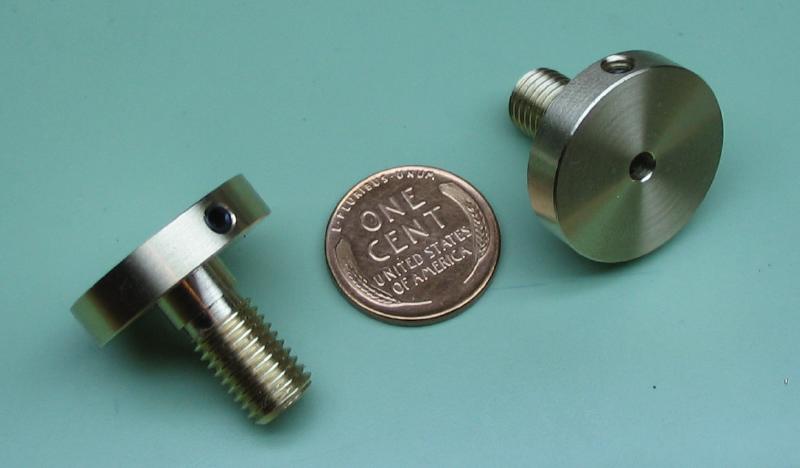
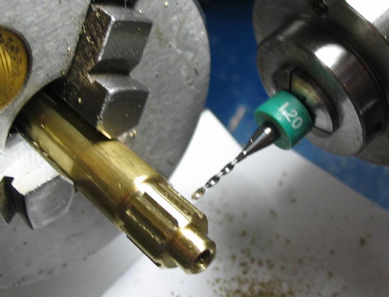
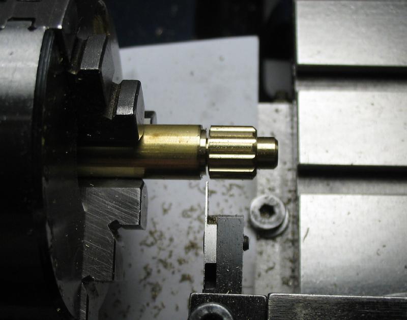
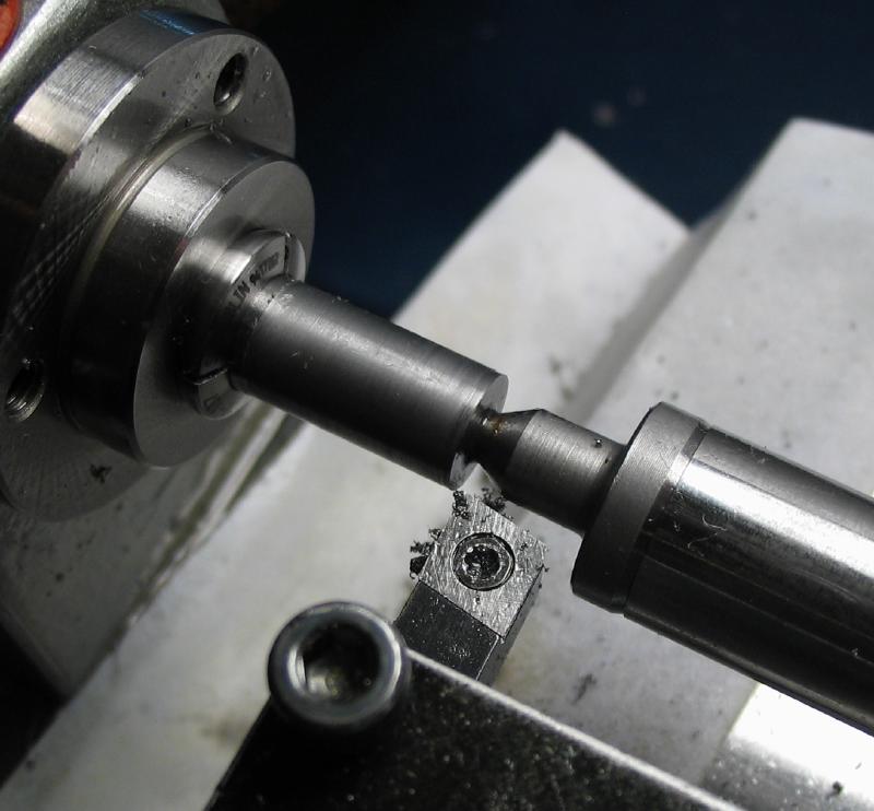
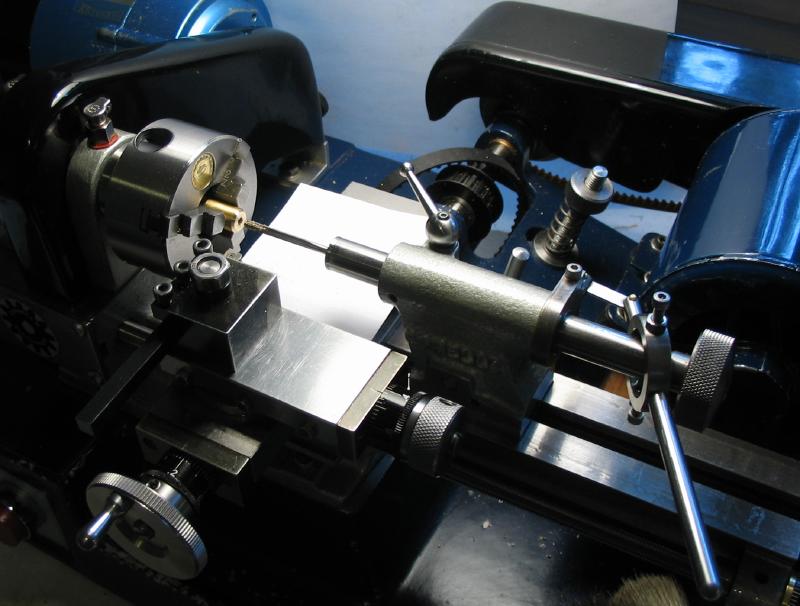
The head portion of the carriers were brought to their final dimensions while mounted on a length of 1/8" drill rod that is held in a collet and the end center drilled for tailstock support. The set screw is brass tipped, and will be used with the completed tool as well.
|
|
|
|
|
|
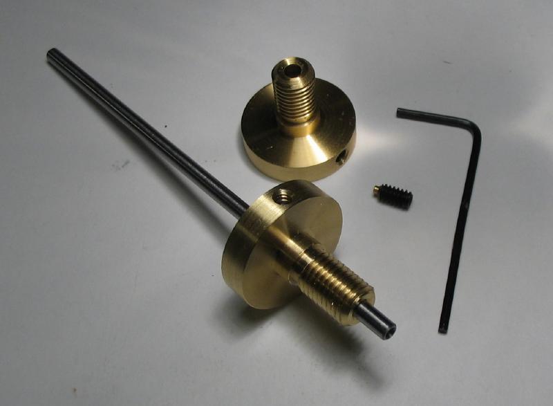
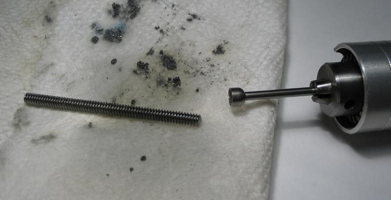
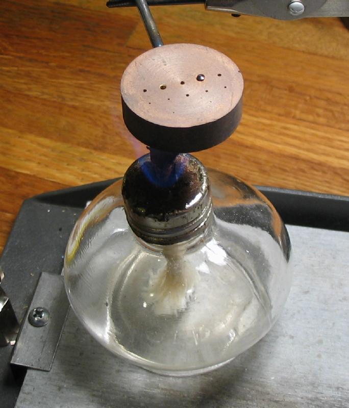
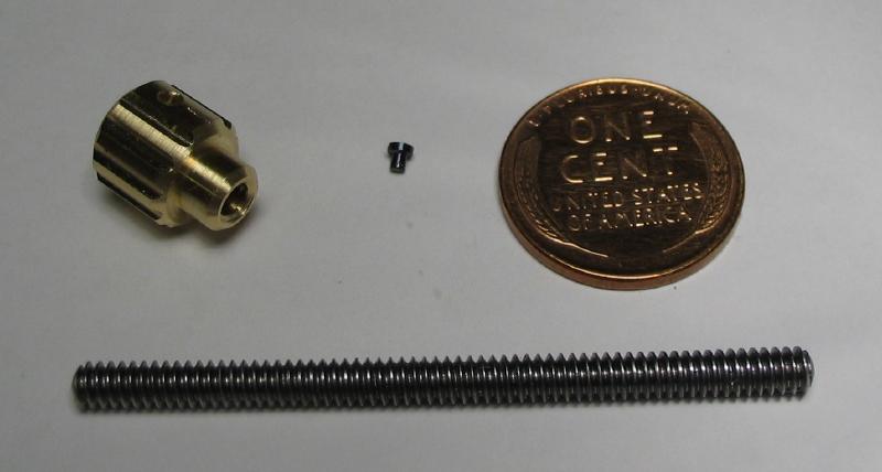
The adjustment feed screw consists primarily of a short length of #6-32 threaded steel rod. It can be purchased by the foot from metal suppliers, and a roughly 2" length was sawed off and the ends rounded over. It will benefit with the addition of a knob, of course.
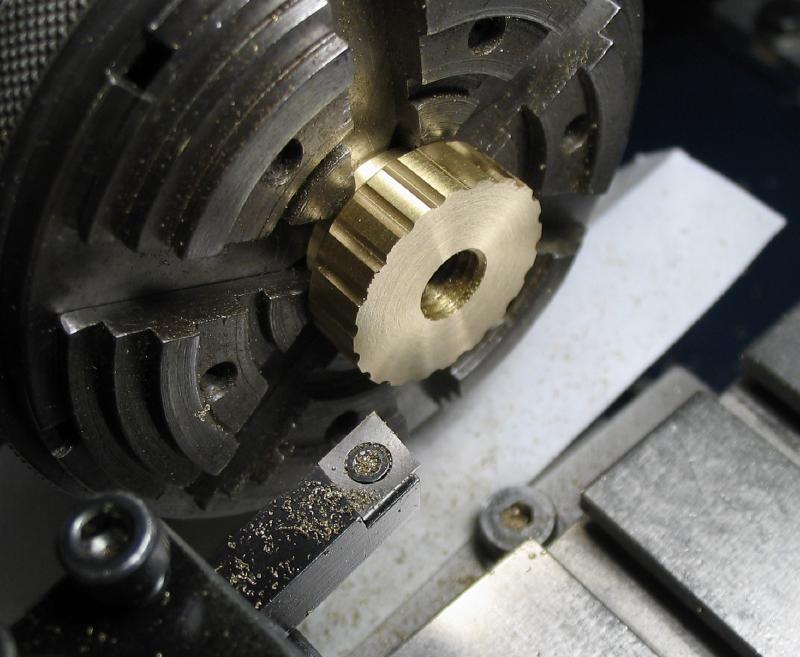
The knob for the feed screw was made from 3/8" brass rod. It was turned round and a shoulder formed. The corners were chamfered and the work drilled through and tapped to fit the threaded rod.
|
|
|
|
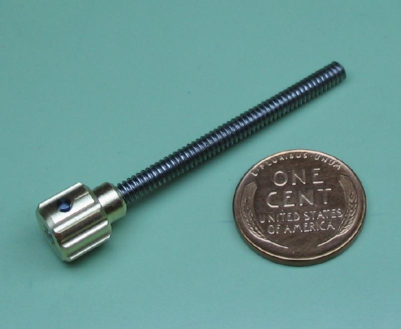
The knob was given grooves with a small ball end mill and indexing for 12 positions. One position was skipped but given a short mark with an engraving bit and then drilled and countersunk with an endmill to fit a small pin. The pin is simply a witness when using the tool, so could have been anything. The work was parted off and the parted face turned.
|

|
|
|
|
|
|
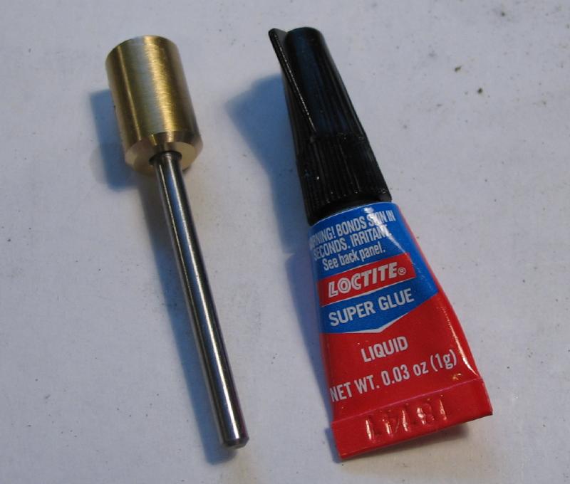
The marker was made from 2mm drill rod. The end was turned to 1.2mm to fit the hole and parted off. The parted face was rounded with a needle file. It was blued with heat, and glued into place and the threaded rod installed into the knob with Loctite threadlocker adhesive.
|
|
|
|
|
|
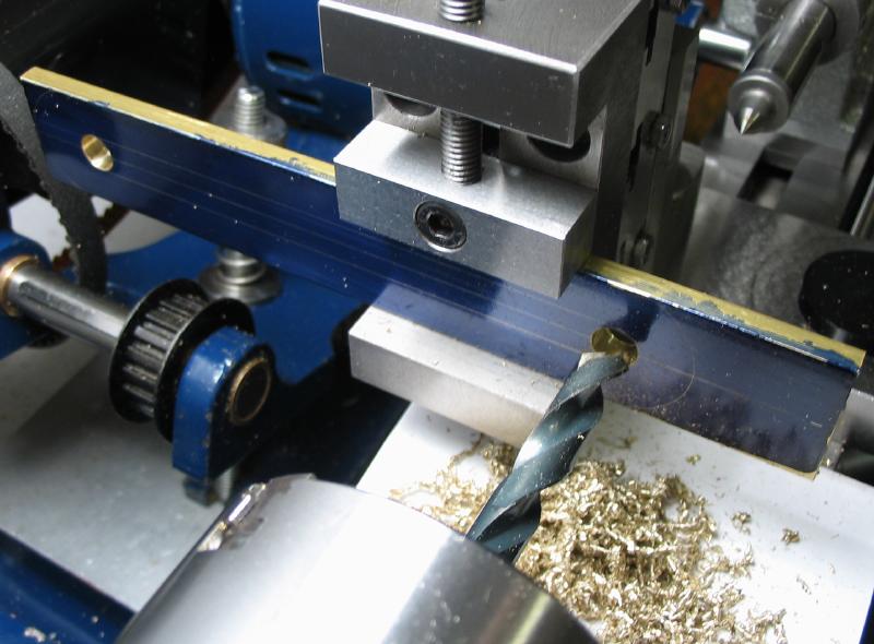
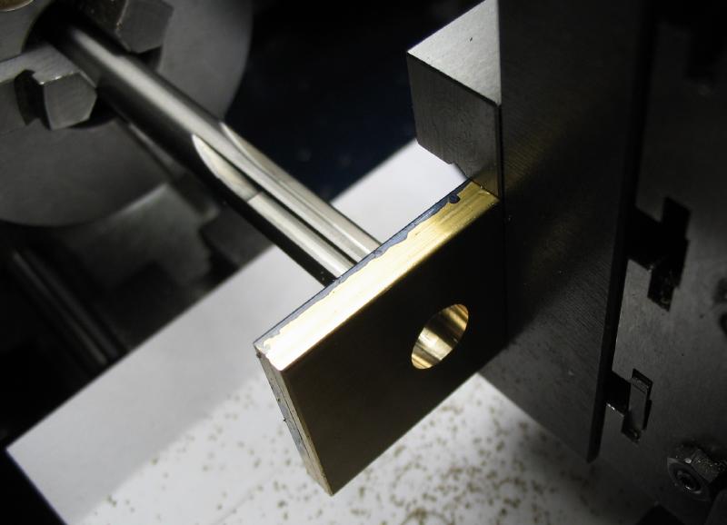
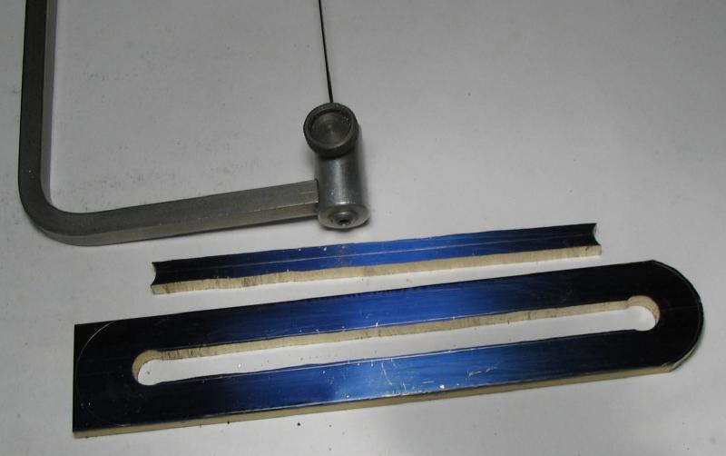
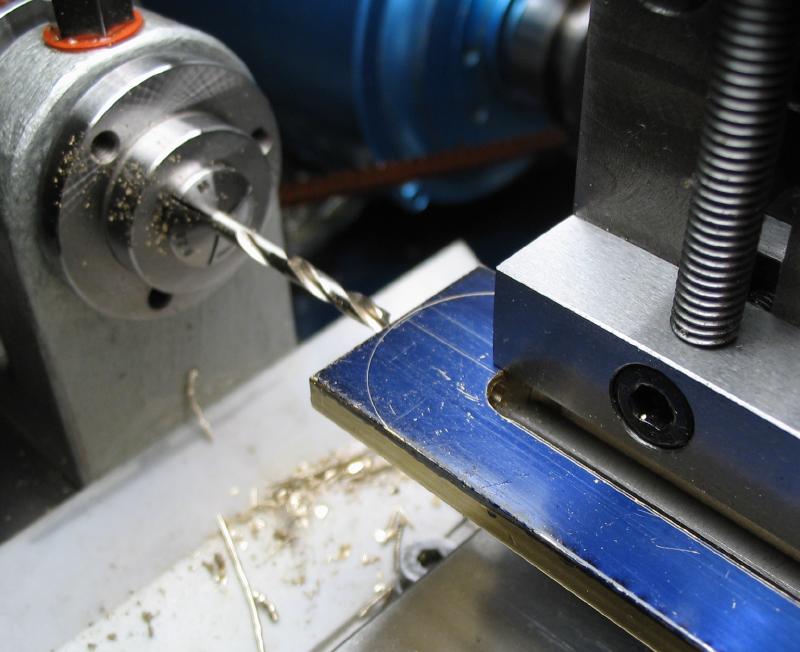
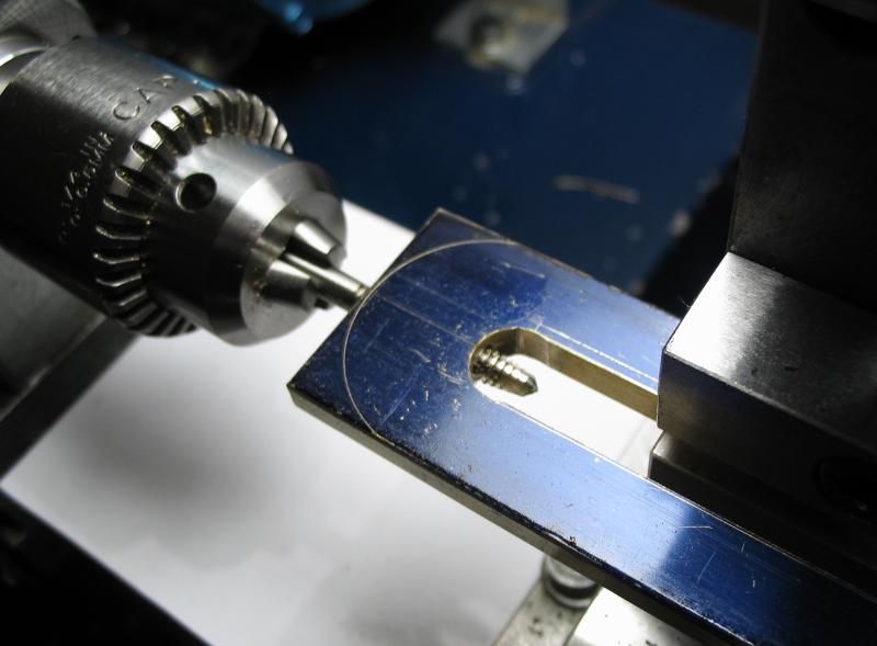
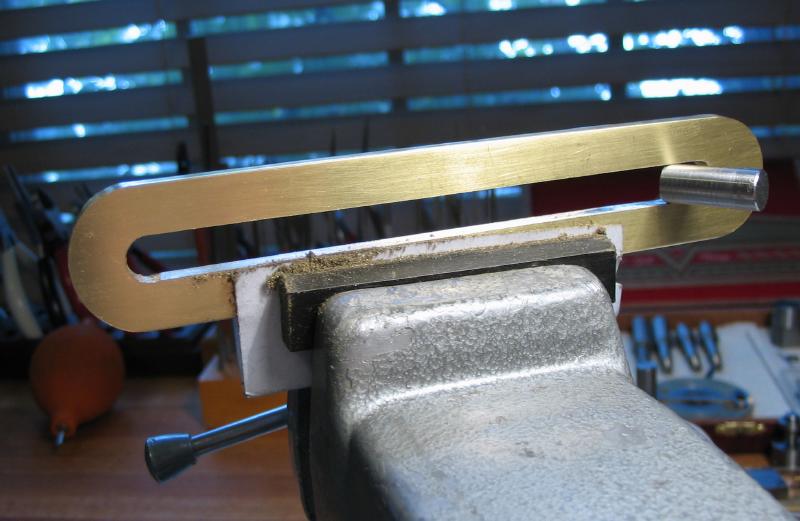
The body of the tool is made from 3/16" x 1" brass bar. The ends of the slot were drilled and reamed 5/16". The slot is then finished by sawing and filing to shape. I started with a 6" length of brass although the final length of the design is a bit shorter than this. It was tempting to make the tool that much longer, however a limiting step when sawing the slot is the depth of the saw frame. Mr. Smith's design reflects the maximum reach of my jewelers saw as well and the relative dimensions can be seen in the last photo.


|
|
|
|
|
|
|
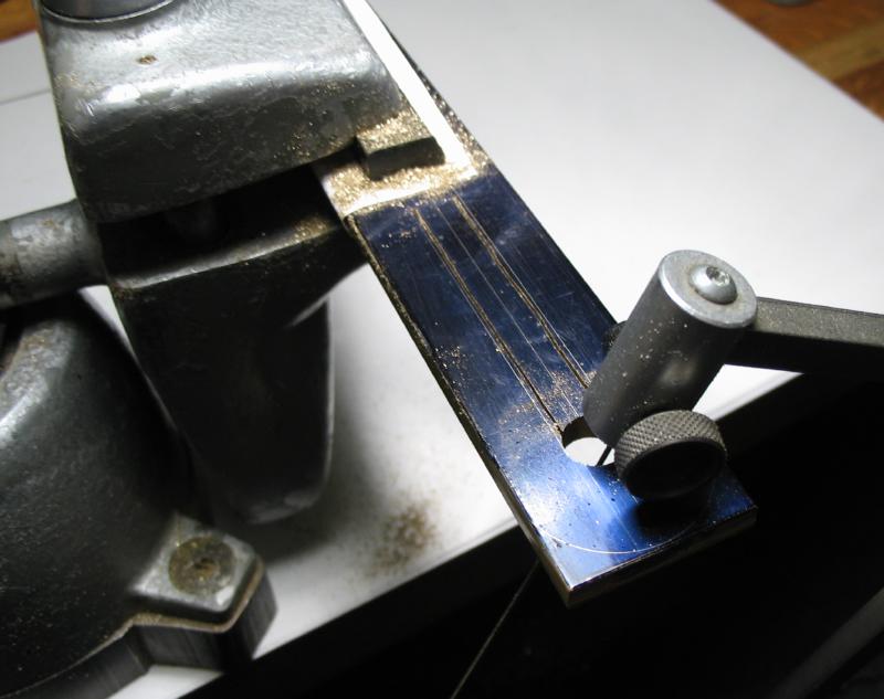
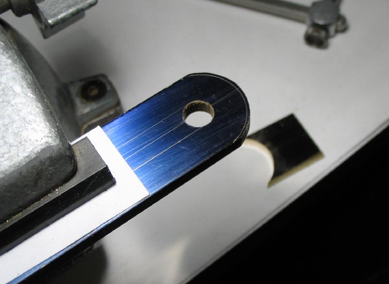
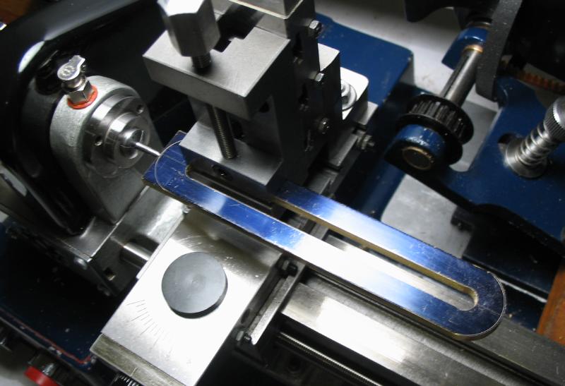
The position for the adjustment screw was drilled and tapped. The vise was loosened slightly so that the work was able to move and the tap was held in a drill chuck and advanced by hand. Afterward, the shape of the plate can be finished by filing. A test gauge was turned from 8mm diameter rod and given a slight taper for checking progress while filing the slot to 5/16" width. In the photo, the test gauge can be seen as it was just starting to fit into the right-hand side of slot; it was snowing outside but did not come into focus in the shot as expected... Cross filing was used to roughly file to size, followed by a diagonal cut that is between a cross and draw file, and the final fitting and finish was by draw filing.
|
|
|
|
|
|
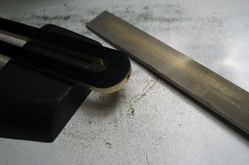
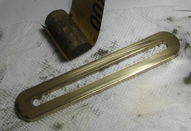
The surfaces were rubbed with 400 and 800 grit emery paper on a half-section of a bottle cork to improve the finish.
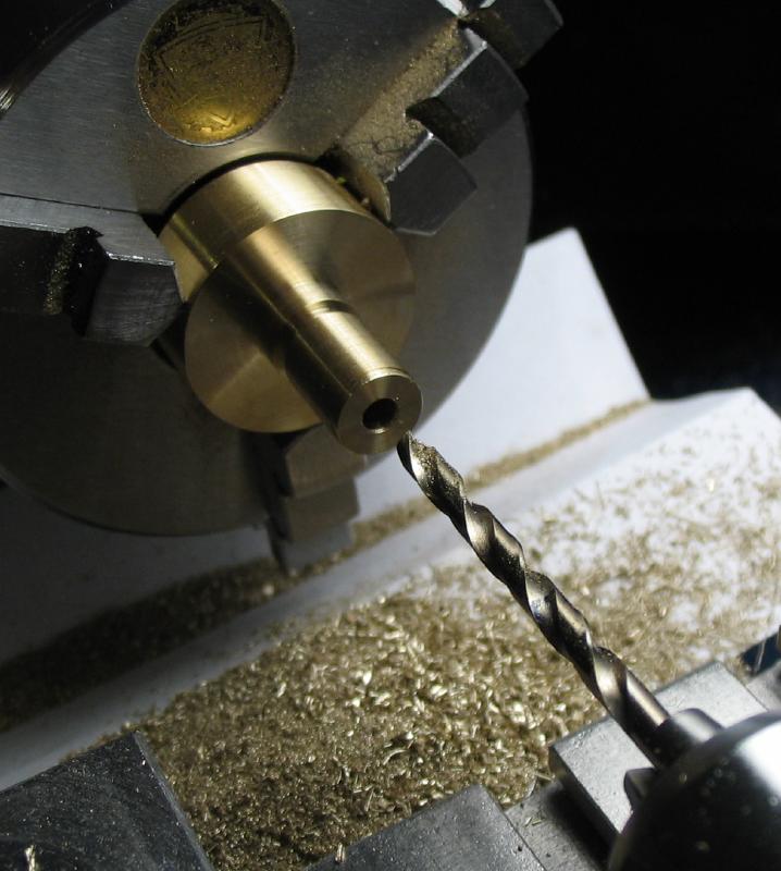
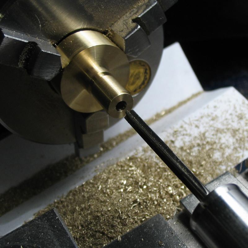
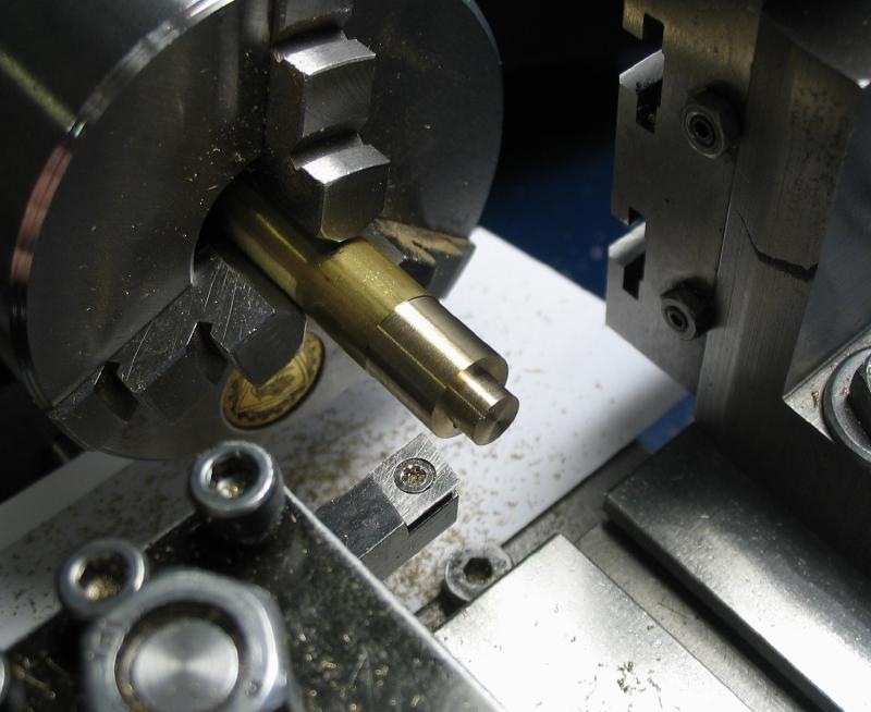
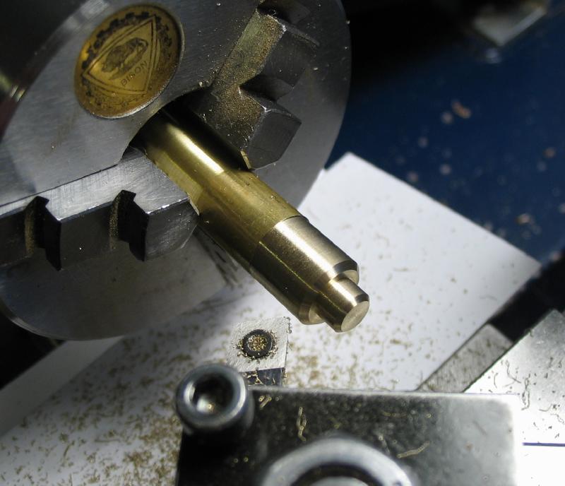
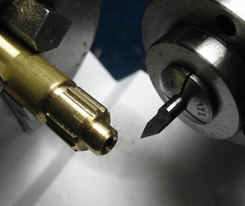
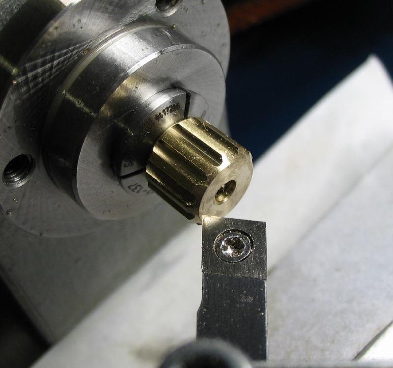
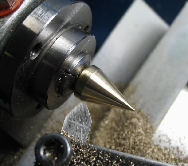
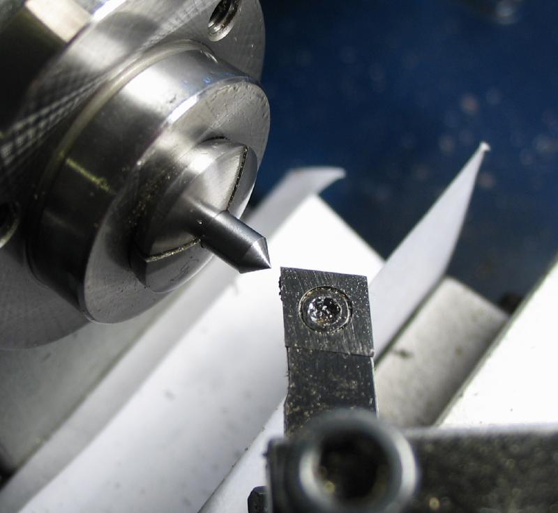
Runners can be made as needed from 1/8" drill rod to fit the carriers. Two runners are shown, one of which has a trumpet point for centering in a hole of the clock plate. It was started from 3/8" brass that was drilled, reamed, and then fit a piece of runner stock with Loctite. The brass was then turned with a 20 degree taper and to a point. It was left attached to this runner, however, it can be removed by heating with torch and the trumpet attached to any runner as needed. In the current case, the other end of the runner was left 1/8", however the tip was chamfered. It is planned to be used for mounting a wheel and a bushing and washer will likely be required - to be continued...
|
|
|
|
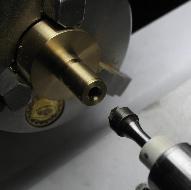
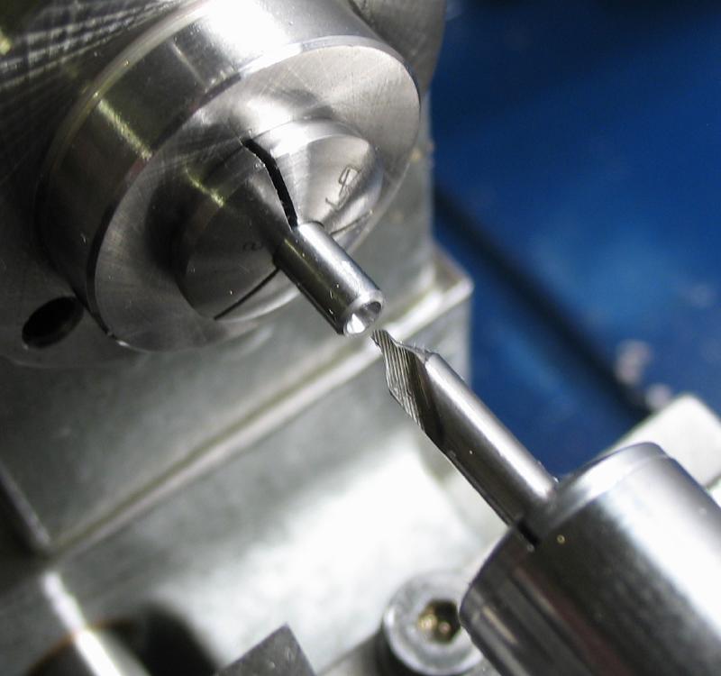
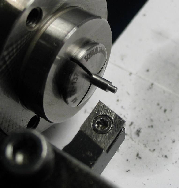
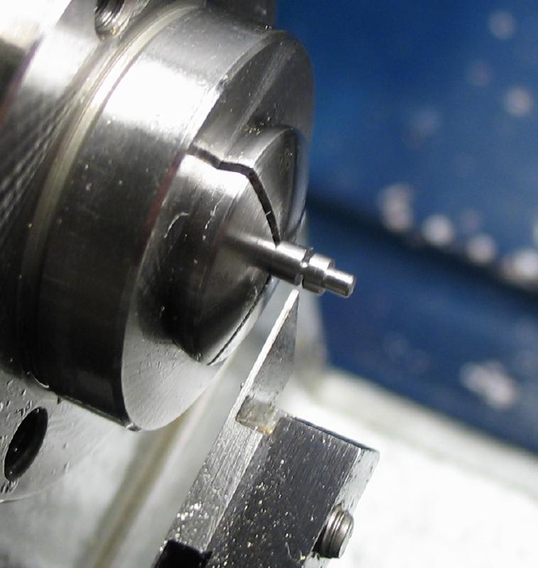
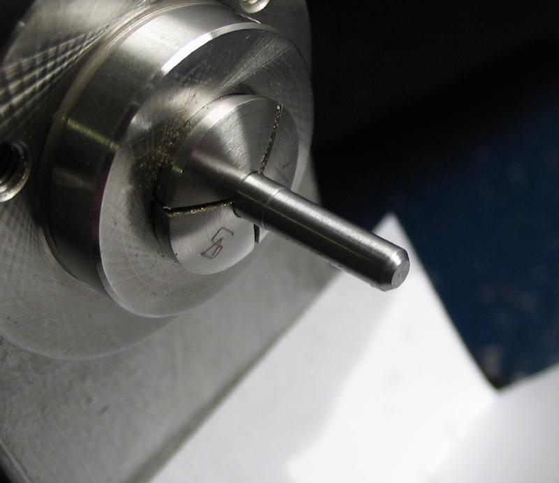
An example pinion runner is shown and it was given a 90 degree point that will act as the scribe and any angle would likely do. The reverse end will fit the bore of a pinion, and in this case planned to be 3mm. It was turned to about 3.02mm, measuring with a micrometer, and then brought to final diameter with a well oiled Arkansas stone.
|

|
|
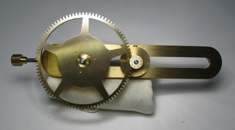
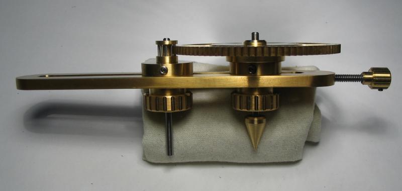
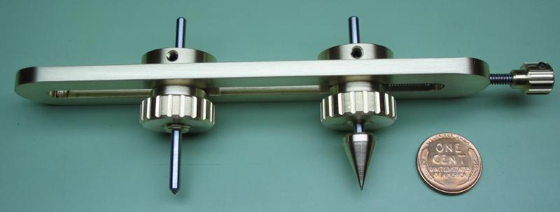
The mostly completed tool is shown below.
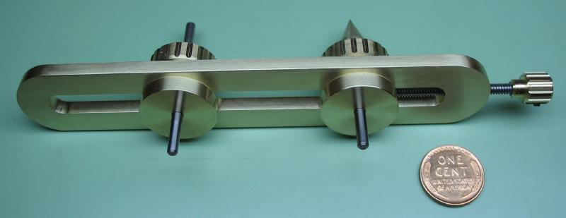
Example of wheel and lantern pinion set up for determining proper depth of engagement.