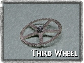
Third Wheel and Pinion
The third wheel is made the same way the center wheel was made, refer to that page for full details.
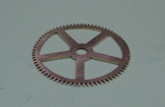
The module is the same, 0.25, however it has 75 teeth. The G3 index plate is required for this count.
The calculations are as follows:
No. of Teeth : 75
Pitch Circle: 18.75mm
Full Diameter: 19.375mm
Root Diameter: 17.875mm
Tooth thickness: 0.3525mm
Addendum radius: 0.5mm
Addendum: 0.3125mm
Dedendum: 0.4375mm
Full tooth depth: 0.75mm
Click below for a PDF version of the complete dimensions.
| third_wheel.pdf |
Third Pinion
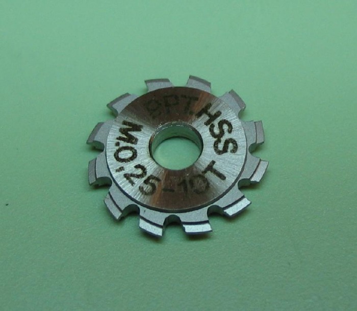
The third pinion mates with the center wheel and therefore needs to 0.25 module. It needs to step up by 8:1, and the center wheel is 80 teeth, therefore the third pinion has 10 leaves. A M0,25-10T cutter was purchased from PP Thornton.
The pinion is a solid pinion, and is therefore made a little differently than the hollow center pinion.
The calculations are as follows:
No. of leaves: 10
Pitch circle: 2.5mm
Full diameter: 2.9025mm
Root diameter: 1.475mm
Leaf thickness: 0.3125mm
Addendum radius: 0.205mm
Addendum form: 1/3 ogive
Tooth/pitch ratio: 2/5
Addendum: 0.20125mm
Dedendum: 0.5125mm
Full Tooth depth: 0.68875mm
Starting with 6mm O-1 drill rod, the basic dimensions are turned, including the taper for the wheel seat. A center is turned to assist with aligning the cutter.

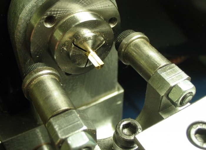
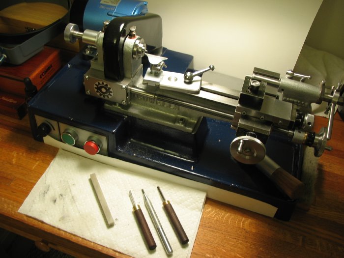
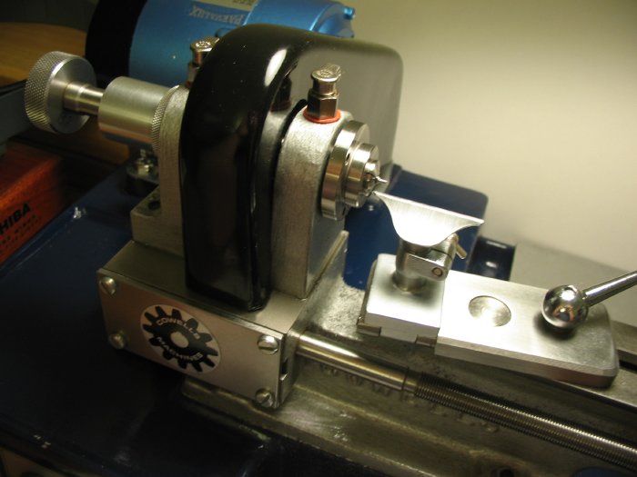
The lathe is then set up for milling the leaves. The headstock pulley is used for indexing the 10 positions. I used the center on the pinion blank and a tailstock center to assure the cutter is squared and centered.
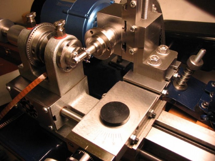
Couple shots during the milling process.
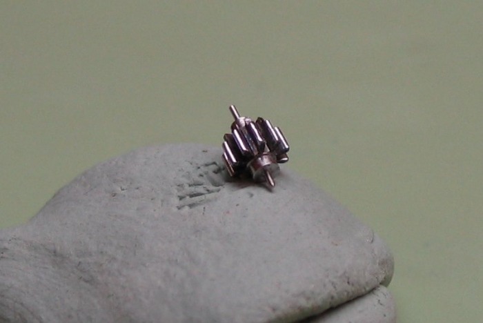
Milling completed in four passes.
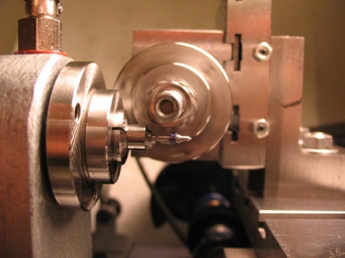
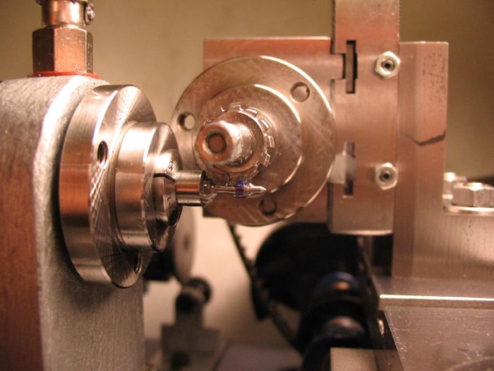
Milling complete.

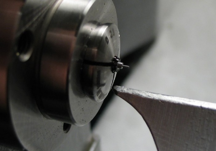
Pinion is parted off and reversed in a collet to fit the leaves. This end is given a center with a graver using the T-rest.

The pinion leaves are polished by hand using a small length of boxwood that has been filed to have knife edges on the ends. One end is used with green (Chromium oxide) polishing paste and the other end used with Simichrome. The soft boxwood conforms to the shape of the pinion leaves during use. This provides a decent polished surface.
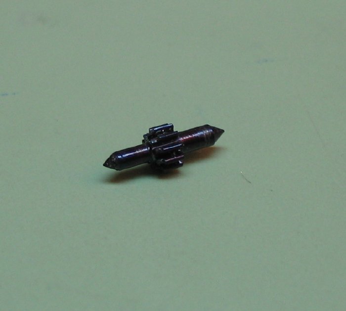
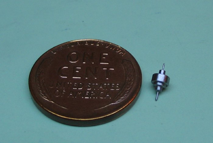
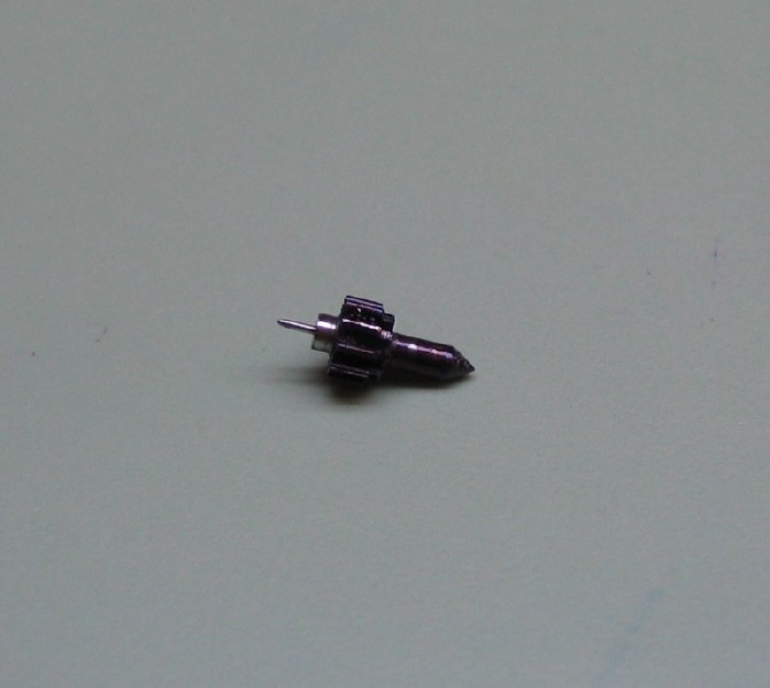
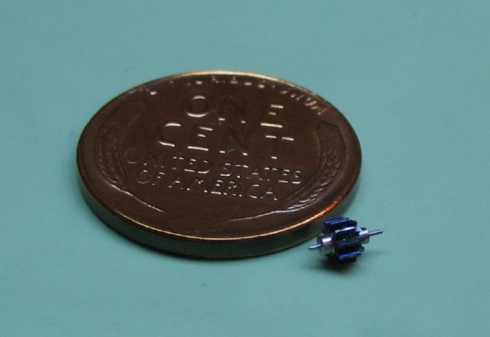
The completed rough pinion.

The pinion was hardened in oil, and tempered to a dark blue color on a bed of brass swarf.
Finishing the Third Wheel and Pinion
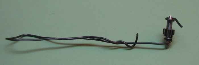
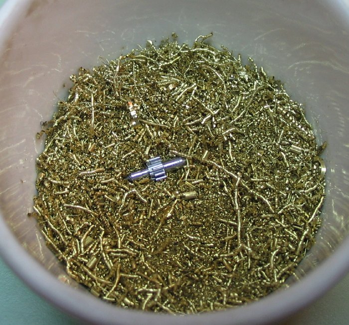
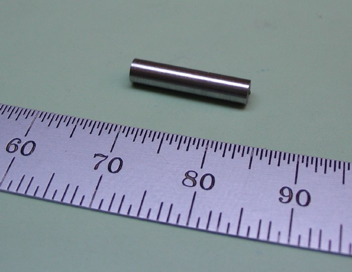
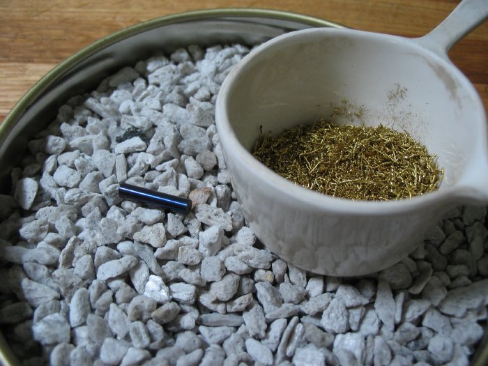
Since the pinion finishing for the third pinion is more delicate than was with the center pinion, I decided to get as much practice as possible for the pinion. I made the dummy pinion by hand turning from tempered steel, this requires much more dexterity than simply turning annealed steel with the toolpost. I started with a section of 3mm O-1 drill rod, fully hardened in oil, and then tempered to a dark blue color. Several steps are shown below. Fully hardened, and the tempered state. The crucible with brass shavings was used to hold the steel rod during the heating to temper.
| third_pinion_finishing.pdf |
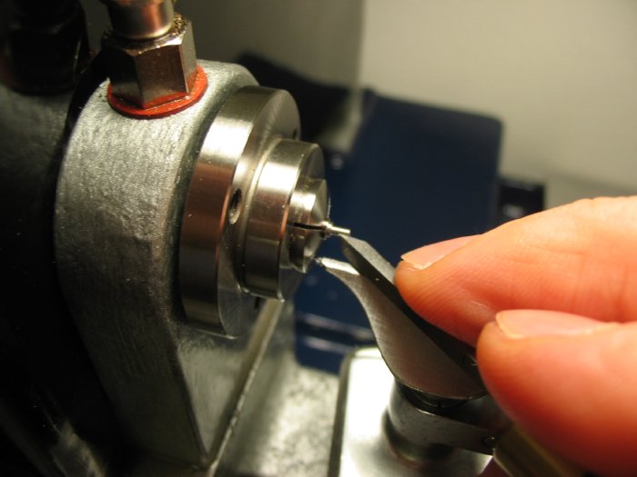
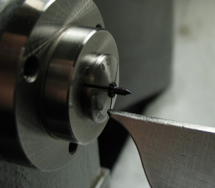
The rod was chucked up in a 3mm collet and a shoulder turned onto the end (1.2mm), followed by a pivot of 0.30mm to match the jewel in the plates. This pivot diameter is suggested in Figure 521 of "Watchmaking" for the third and carriage pivots.
The pivot is quite delicate, extra practice in turning these small diameters is never time wasted. It is a skill that increases proportionally to the time spent doing it.

Trying to show how the graver is used, but one hand is holding the camera, so not very useful...
The other end of the dummy pinion was turned, including a seat to test fit the wheel, and turn the shoulder and pivot. It is test fit to the movement and modified until the correct fit can be determined. Since it is the dummy, going back and forth between the lathe and the movement can be done until it's right. When turning the actual pinion, this must be kept to an absolute minimum to avoid errors. The dummy is used to compare to the pinion during finishing.
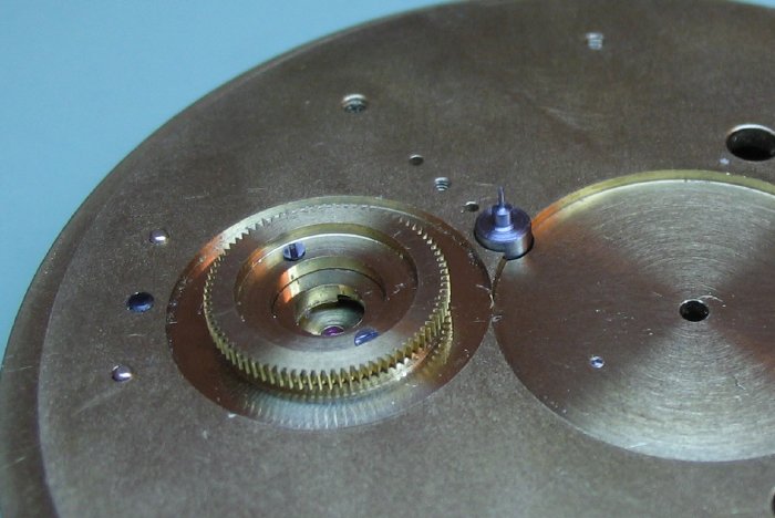
The following photos are not easy to see, but the dummy pinion is installed and potences screwed in place.

The third pinion can then be compared to dummy pinion to start planning its finishing strategy.

The pinion is lightly chucked in a collet by the leaves. It can be trued using the face of the graver against the edge of the leaves. Then the collet is tightened. Using the dummy pinion as a guide, the pivot and shoulder was turned on the top side. If you recall the center pinion progression, I started with the wheel seat rivet side, however, with the third pinion I need to ensure the depth of the wheel, so that the third wheel will be flush with dial side recess in the mainplate. Therefore the top side of the pinion was finished first.
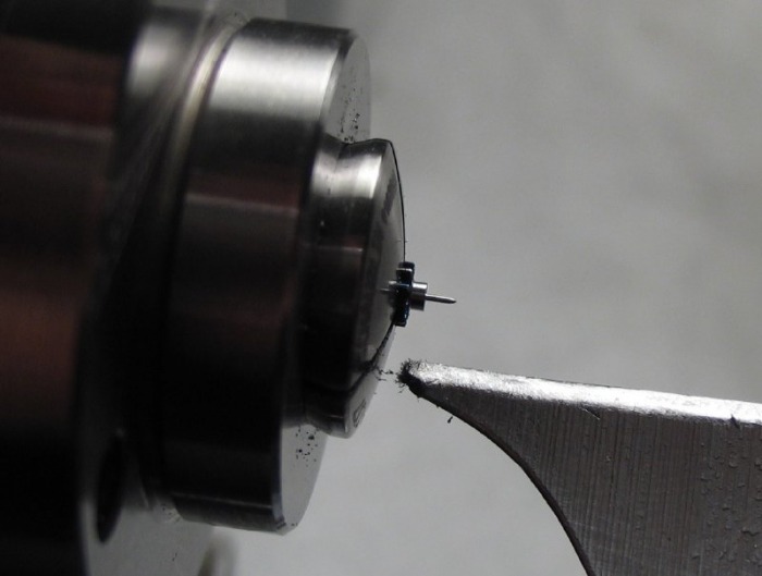
The dial side of the pinion can be turned, including the rivet for the wheel seat, the shoulder, and the pivot. Again, the dummy pinion is used as a guide.
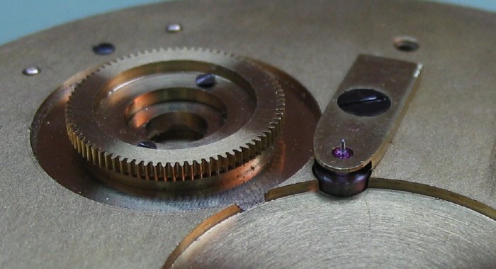
Testing the fit.

Prior to tempering blue, the pinion was polished with green polishing paste (chromium oxide), so now it can be finished with Simichrome with a sharpened piece of wood (same as done on previous pinions).
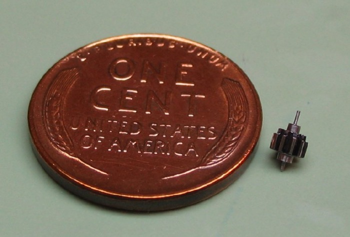
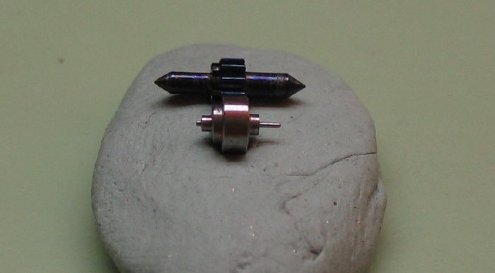
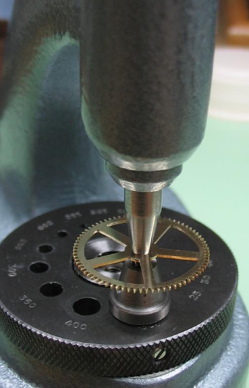
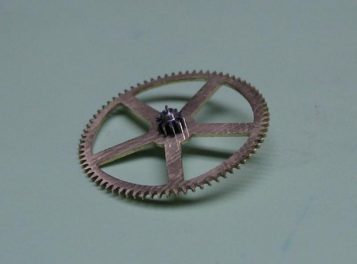
The wheel and pinion can be staked together. More detail of the process is found on the center wheel page.
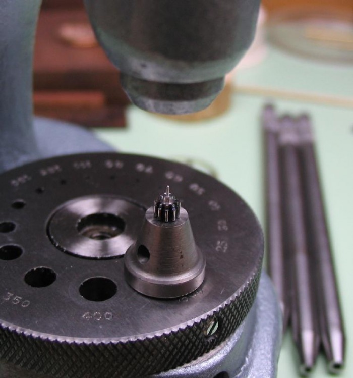
To burnish the pivots I needed to make a support bed, as the Jacot attachment made previously did not include pivots this small, an oversight on my part.
I turned a piece of 1/8" brass rod (type 360) to 3mm. In a 3mm collet the rod was drilled 0.30mm. The roller filing rest was used to file the rod in half, forming a bed that can support the pivot.