Making the Geneva Stop-Work
After making the barrels, the most obvious next step would seem to be the barrel arbor. However, this watch will be using stop-work, and the finger piece of which is driven by the arbor. It must be made first since a square hole is more difficult to make to exact dimensions than is a squared arbor, so the finger piece will be made first and the barrel arbor made to fit.
Stop work is rarely found in currently manufactured watches. Stop work is a mechanism fastened to the barrel and whose object is to stop the winding before the spring is completely coiled around the arbor hub. This same mechanism also stops the running of the watch before the spring is completely pressed against the inner wall of the barrel ; in effect, its purpose is to utilize only a part of the development of the spring, during which the force is most equal. This makes it a suitable addition to a high precision watch. Thus, for example, if the total development of the spring is six turns, and the unwinding is arrested by the stop-work after four turns, the spring will still be stretched one turn when the watch stops, effectively 2 turns of the spring never being "used" . Since the stop-work will allow four turns, each of which amount to 8 hours, then the watch will run for a total of 32 hours.
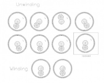
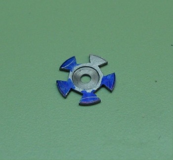
The typical form of stop-work found is referred to as "Maltese cross" or Geneva stop-work. It is composed of two pieces, the 'finger' and the 'star wheel', the latter being shaped like a Maltese cross. The star wheel is placed on the barrel, where it can turn freely, while the finger is placed on the arbor. The head of this finger gears in the notches of the cross, the rounded out teeth of which can successfully slip around the circumference of the finger piece. During winding, the owner is effectively turning the barrel arbor; the finger participates and, at each turn, pushes a tooth of the cross until the moment when the shoulder of the finger comes in contact with the full tooth of the cross; at which point the watch is 'wound'. While the watch is running, the finger is stationary and the cross, turning with the barrel, at each turn presents one of its openings in front of the end of the finger, which forces the cross to make a fraction of a revolution on its axis. After four such revolutions of the barrel, the other shoulder of the finger comes in contact with the full tooth of the cross, and the watch will stop.
Daniels affixes the stopwork to the underside of the barrel, I will follow this method as well. David Glasgow (Watch & Clockmaking, 1885, page 77) advises against this;
"... The Swiss always fix [Geneva] stop work on the barrel cover, but some of the Lancashire movements have it on the barrel. This arrangement is bad, for these reasons : The barrel hole being in the same plane as its teeth, or wheel, there is more friction in that hole than in the hole in the cover, and, therefore, the pivot should be as long as possible and have oil kept to it ; the sinks turned out to receive the stop work necessarily weaken the part of the barrel to which it is applied, and render it more liable to be spoilt than the unweakened part, and any injury to the cover is easier remedied than if it occurred to the barrel. In the event of a barrel being damaged from this cause, it can be rectified by turning out the bottom, snapping a new one into the groove, similar to the one into which the cover is snapped, and riveting over... "
Daniels provides a method for making the stop-work components, however, he does not provide complete dimensions or formula for determining them, instead he instructs to draw at 20X scale and take dimensions from the drawing. J. Malcolm Wild does provide the means to calculate the complete dimensions of Geneva stop-work in his book, "Wheel and Pinion Cutting in Horology.” I used his formulae and a rather backdoor approach to determine the dimensions from Daniels work to arrive at a complete set. Wild's calculations are based on the center distance (CD) of the finger piece to the star wheel. From Wild's formulæ, advice from Jules & Hermann Grossmann's "Lessons in Horology" (1905), and some actual measurements taken from a high-resolution scan of Plate III of Daniel's "Watchmaking" and using a program called ScreenCalipers, one can make some conclusions as to the dimensions needed. One step in the actual machining of these components is the milling of the star wheel tooth space. After some difficult searching for slotting mills that would be amenable to this task, I concluded this was going to be the limiting step. So, for a first attempt at this, I back-calculated the dimensions based on a solid carbide mill with a 1/16" thickness, hence a tooth space width of ~1.5875mm and with equation (3) a CD of ~5.5mm was determined.
Finger Piece
1) Ø Blank = center distance (CD) x 1.2 = 6.6 mm
2) Finished Ø = CD = 5.5 mm
3) Ø of finger holes = CD x 0.20 = 1.1 mm
4) Holes at 38°
5) Radial dist. of holes = CD x 0.448 = 2.464 mm
6) Width of finger = CD x 0.29 = 1.5875mm (1/16")
Maltese Cross
1) Ø Blank = CD x 1.24 = 6.82 mm*
2) Ø Concave = CD = 5.5
3) Width of Slots = CD x 0.29 = 1.5875mm (1/16")
4) Depth of Slots = CD x 0.26 = 1.43 mm
* This is the full tooth diameter, which is explained more fully by Grossmann, where it is recommended to make the full tooth with a radius longer than that of the cut-out teeth, in order to cause the stoppage a little before the line of centers.
Click the link for a complete technical drawing in PDF format
| stopwork.pdf | |
| File Size: | 247 kb |
| File Type: | |
Both the finger piece and Maltese cross are machined from 7mm oil hardening (O-1) drill rod.
The Stop Finger
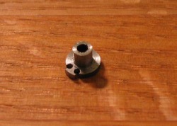
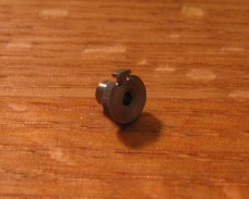
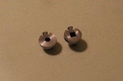
Daniels' method of making the finger piece is to mill the general profile with an angled cutter and then finish by hand with files. Wild’s method is quite similar but first drills the recesses for the star wheel corners, so that they are accurately placed and to size. The finger piece has a boss which actually functions as the lower pivot of the barrel, so must be treated as such in its execution. This is not illustrated in figure 289 of my copy of “Watchmaking” (the first edition), where the boss is absent.
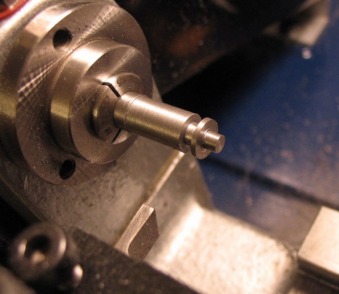
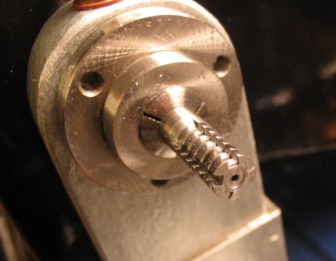
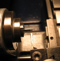
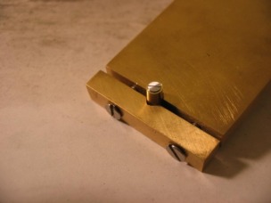
The 7mm drill rod is turned to diameter (6.6mm) and the pivot dimensions formed, including a shoulder, and with a parting tool, the beginnings of a second finger piece is formed behind the first. This also gives clearance for the milling cutter.
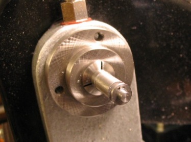
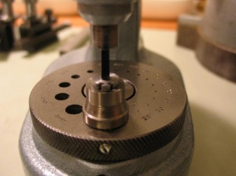
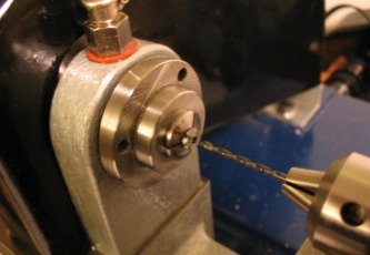
The headstock was locked and the drilling spindle setup on center and using the cross and vertical slides feedscrews, the hole positions were located and drilled 1.1mm. I used the dimension function in AutoCAD to determine the X and Y distances, but these could be determined by trigonometry as well.
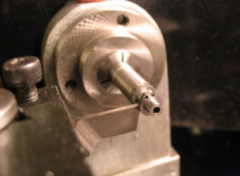
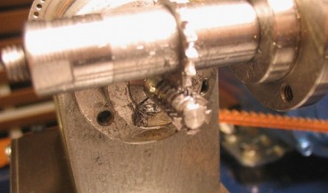
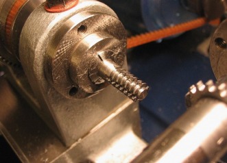
I then set the milling spindle up for gear cutting using a Thornton ratchet cutter, this is likely a misuse of this expensive cutter, but it was the means I had found. I apparently was too involved to photograph the setup, but it is very similar to the method in "Watchmaking," where the ratchet cutter was fed into the part, headstock locked, with the flat portion of the cutter forming the right side of the finger. The headstock was then carefully unlocked and turned slowly by hand to mill the round portion of the part, stopping as I approached the left side of the finger. Here is a photo following the milling and ready to part it off the stock.
The finger is finished by hand with various files to dimensions that allow easy engagement with the star wheel.
If you refer back to the section on making the winding ratchet wheels, I describe the formation of square holes using a special made broach for the staking tool. I use that same punch to form the square winding hole in the finger piece. It requires a bit for care, stopping after a couple hammer blows to clear the chips away (reaming on the lathe) and then continue until the broach clears the length of the piece.
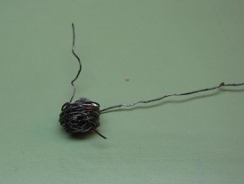
After fitting the starwheel to the fingerpiece, both can then be hardened and tempered blue. These delicate parts are wrapped in fine iron wire, which will help absorb some of the oxidation from the flame and help prevent warpage as well.
The Maltese Cross
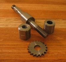
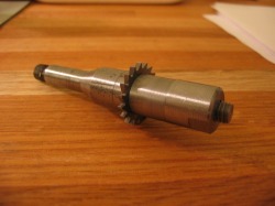
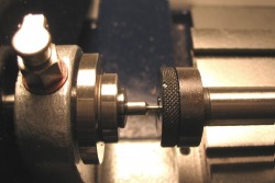
The slotting cutter has a bore diameter of ¼" and I therefore needed to make an arbor for holding it. I used the wheel cutter arbor supplied by Cowells as a model for making this one. The wheel cutters have a 7mm bore which, of course, is 0.65mm too large. I started with a collet blank (an Ebay find) and turned a shoulder for the cutter and reduced a length of the end to be threaded M6x1.0. I made a counterbored nut to suit from a section of ½" C1018 steel rod; drilling 5mm, boring a small portion to ¼" and then tapping with an M6x1.0 tap in the tailstock. It was chamfered and filed to allow for easy tightening with a wrench. I made the arbor intentional a bit oversized, so that it might be useful for holding other, larger, ¼" bore items, perhaps a grinding wheel, etc. I therefore needed to make a washer to take up the extra space with the cutter at hand.
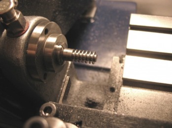
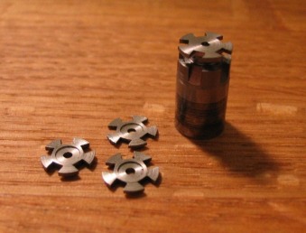
The star wheel begins as a section of 7mm O-1 drill rod and reduced to 6.82mm OD, which is from the calculations above. Using a parting tool, sections are made, reducing the rod to a diameter equal to the depth of the star wheel teeth (3.96mm OD), this can therefore serve a guide for the feed of the slitting saw. This base diameter becomes very important during the milling process, since fitting a caliper, etc. isn't possible, so it acts as the only reference for depth of feed.
The milling was performed at medium speed, 1100 RPM, and in increments of about 0.3mm of depth, until the final pass of about 0.02mm. Indexing was done using the division on the headstock pulley (60 ÷ 5 = 12 divisions). After each pass of the cutter, I brushed the chips clear and applied a few drops of cutting fluid (TapMagic), the slots held the fluid in place by capillary force and helped clear the chips as well.
Following the milling of the slots, the rod was center drilled and then drilled 1.2mm for clearance of the boss formed on the barrel. The base diameter portion extending out from the post was then faced off, and a recess formed for the screw head (3mm Ø x 0.2mm depth) using a Micro100 carbide boring bit. Daniels makes a typographical contradiction, indicating in figure 292 a shoulder height of 0.2mm, but following the text, should be 0.3mm allowing for 0.2mm of screw-head depth.
Star-Wheel Retaining Screw
This is my first attempt at making a screw, and it is a relatively small one at that. I have cut threads a few time using various dies, but at much larger diameters. I didn't photograph the threading, but I did take some shots while making another, larger (1.5mm) screw, the process is the same, using the Bergeon dies and holder. I made a pusher for the tail stock that keeps the die holder perpendicular to the work.
The star-wheel screw has a head diameter of 3mm, so starting with 3mm O-1 drill rod, a 0.5mm portion is turned about 1mm in length. After cutting the thread the screw is parted off with a little extra material for polishing the head flat.
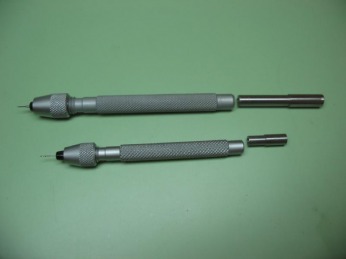
I made a little brass arbor to hold the screw in a collet, it is simply a piece of brass rod turned true and held in a collet to face, drill and tapped to match the screw thread. I used pin vises to hold the small tapping drill and tap. I made a couple arbors that can be held in the tailstock to keep the pin vises in alignment, while they are fed by hand into the revolving work.
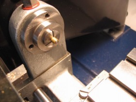
The screw is inserted in the arbor
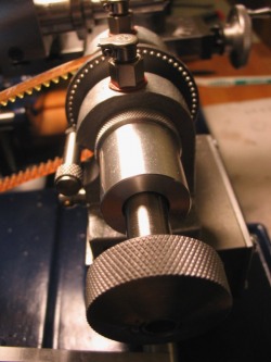
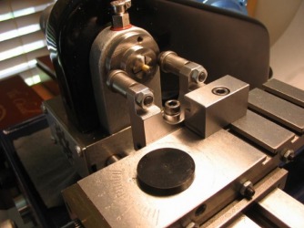
The filing rest is installed
(note I made a Delrin plug for the compound slide hole)
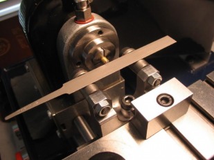
The height is adjusted so that the screwhead file is on center (headstock is locked)
Polish the head using the bolt tool and some various grades of emery paper
(note: this was not my first screw, there is a small pile of unacceptable ones!)
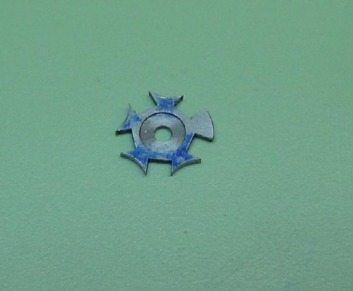
After the barrel arbor is fitted to the barrel, and the finger piece can be put into place, the recesses for the star wheel can be marked out. This is done, as Daniels describes in figure 289 of 'Watchmaking.' The star wheel is coated in blue Sharpie and is screwed into position. The finger piece is lowered onto the star wheel with the hub diameter atop each of the fingers of the star wheel. This diameter can then be scribed onto the fingers to provide the required depth and shape of the recess. The recess is then filed out with half-round and crossing files. Great care must be taken during this process, since any extra material will bind the finger piece, but remove just a little too much and the finger piece will not correctly engage the star wheel.
