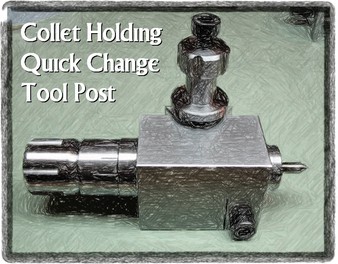
Collet Holding - Quick Change Tool Post (QCTP)
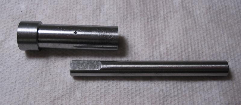
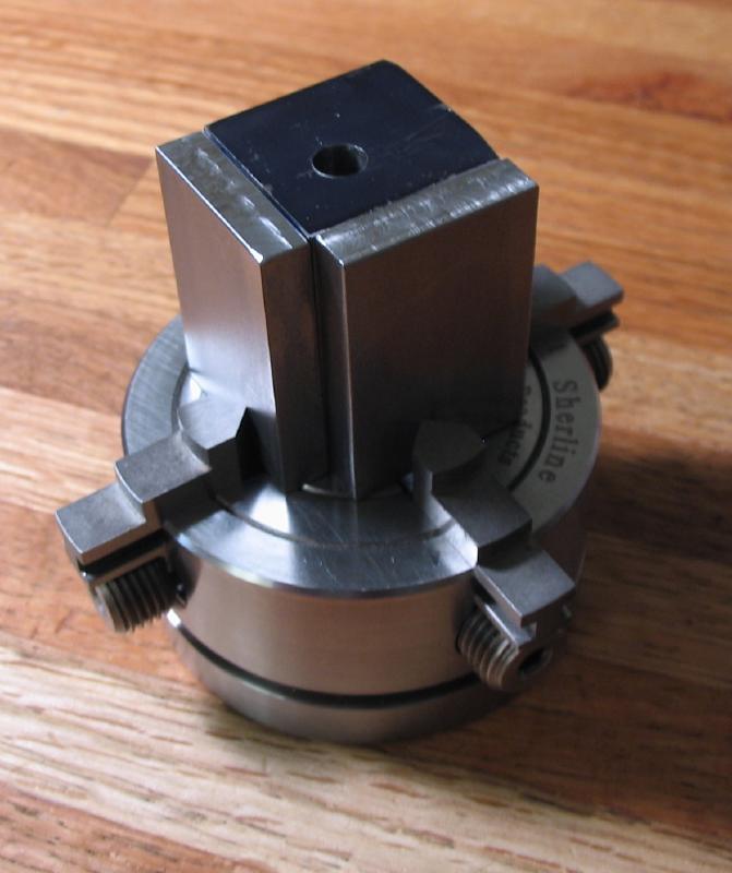
The Collet Spindle
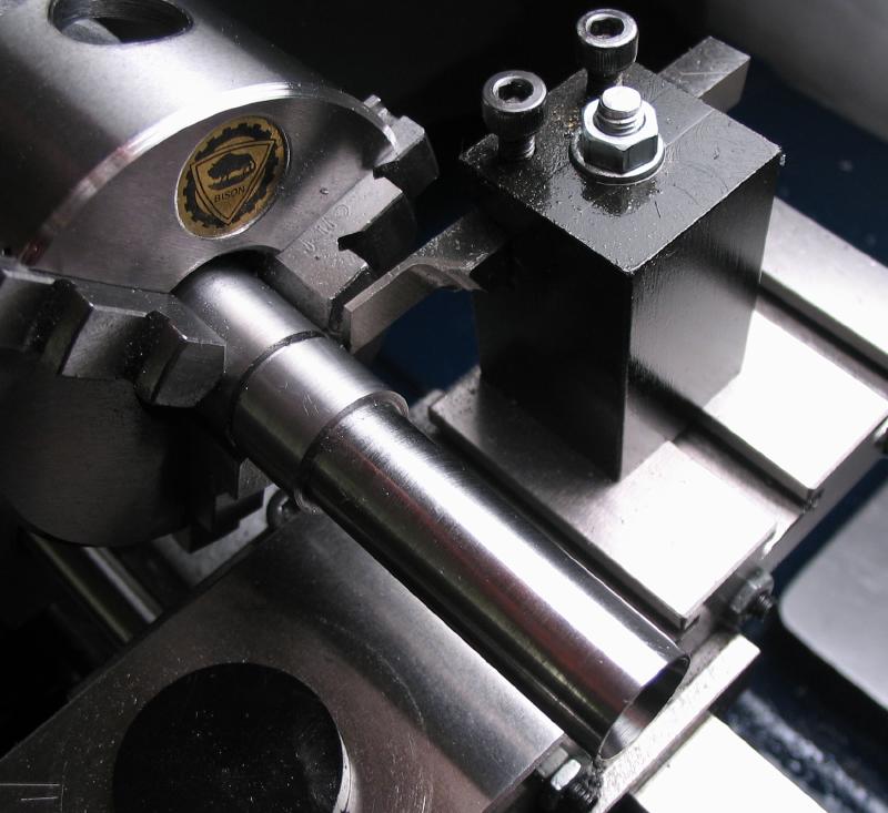
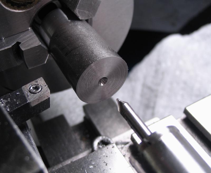
The spindle is made from 5/8" mild steel (type 1018). It was faced and center drilled using the steady rest. The rod was turned down to 15.5mm and then reversed in the chuck.
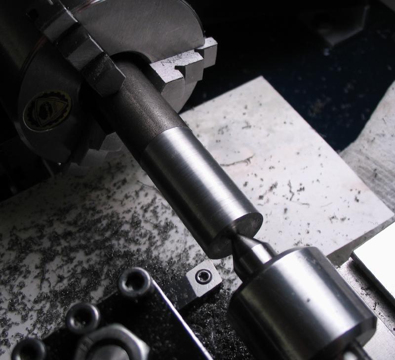
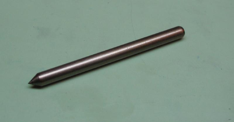
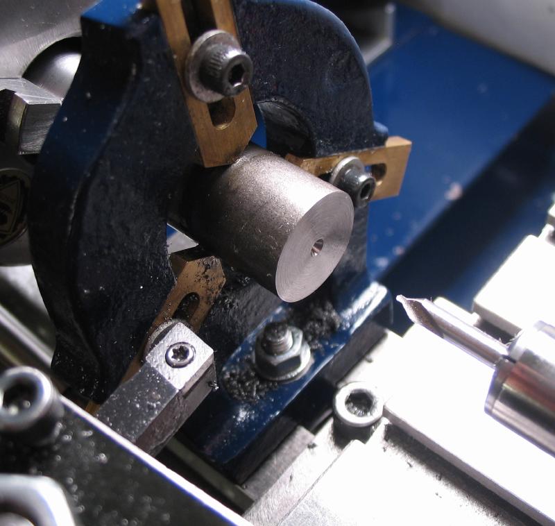
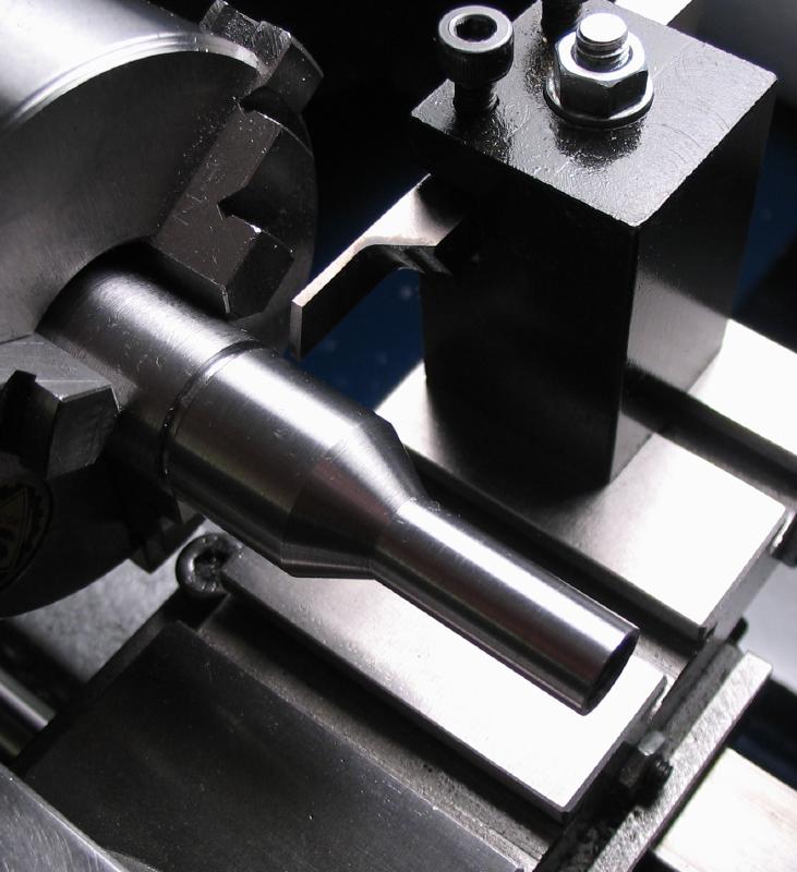
The rod was turned down to 1/2" for a length of 40mm. Since a provision for rough indexing or rotational positioning is planned, this diameter will benefit from some decent and smooth finish. Since mild steel was used, the spindle was simply burnished to smooth and work harden the surface. A rather large 1/2" wide burnishing file was found at a used tool dealer's stand. Plenty of cutting oil was applied to the burnisher (Cool Tool II).

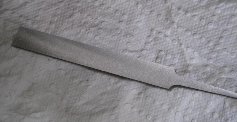

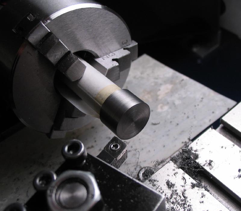
Resulting surface
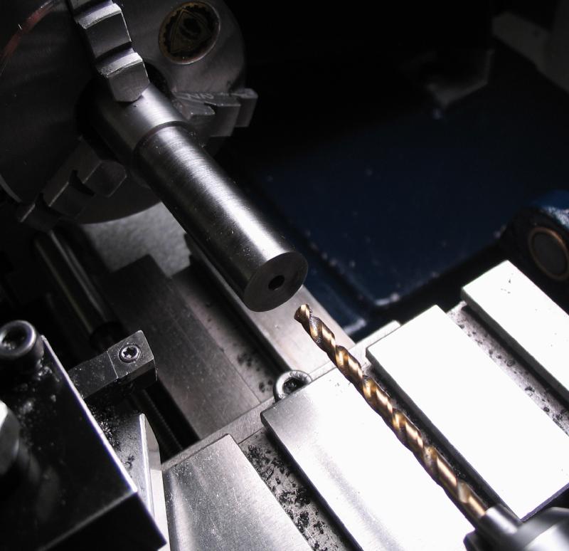
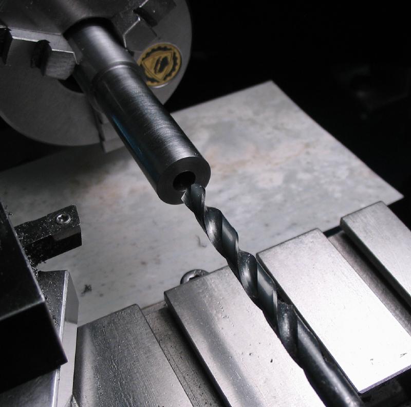
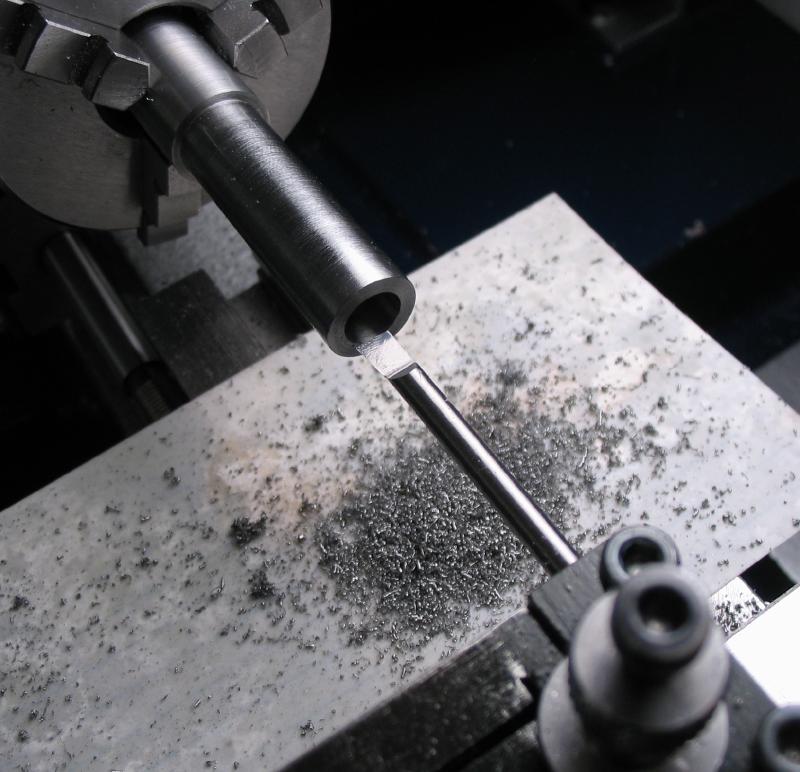
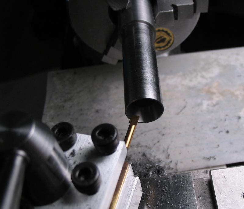
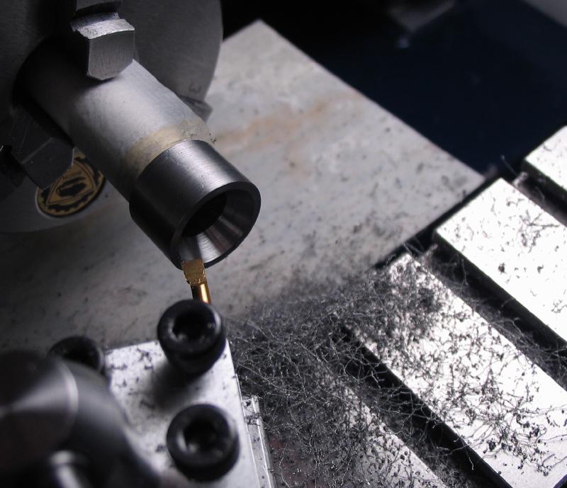
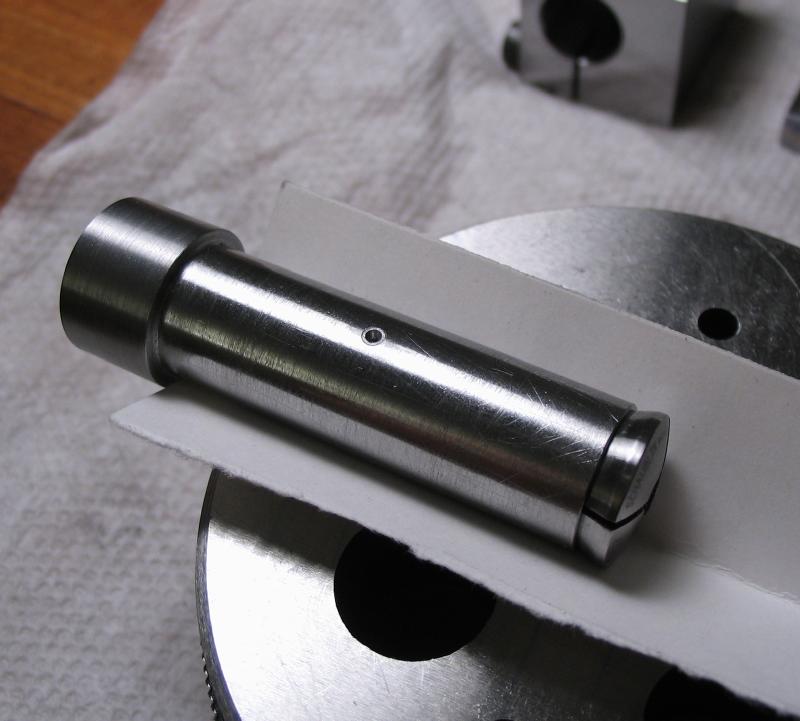
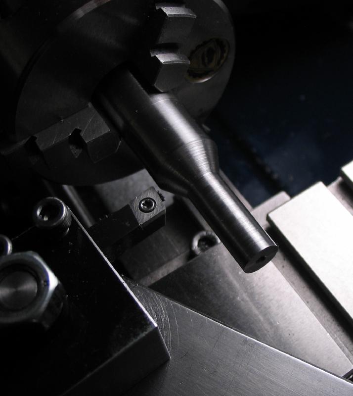
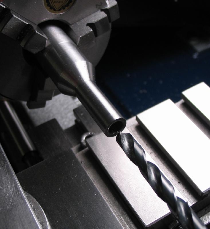
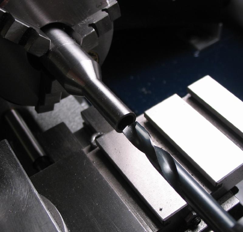
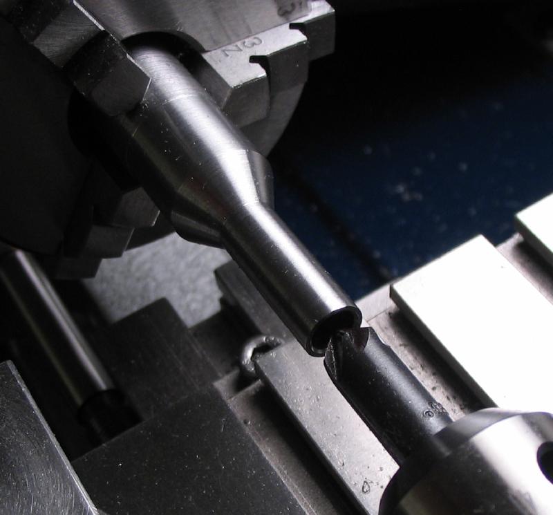
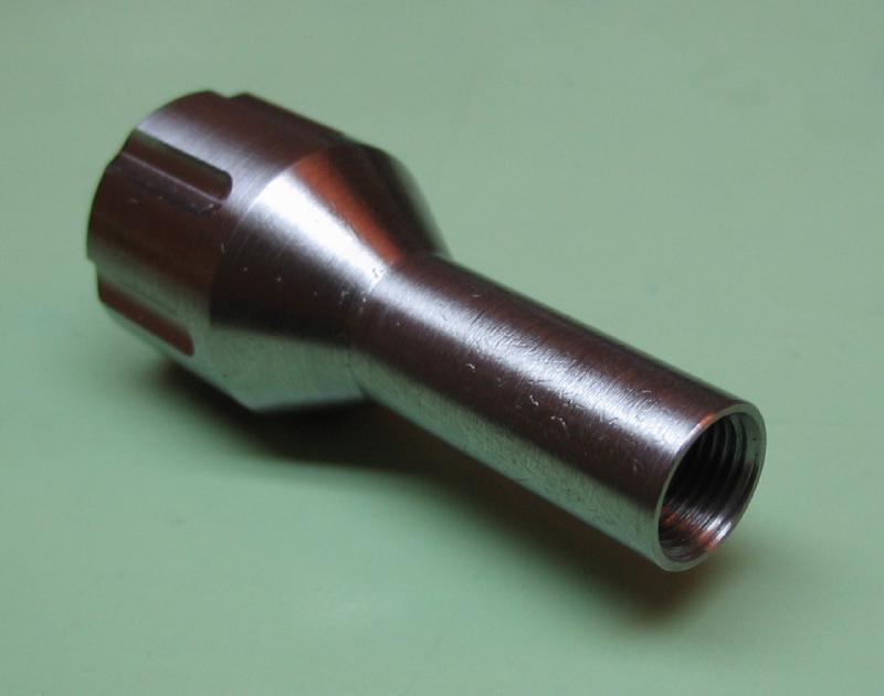
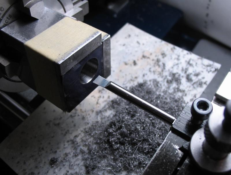
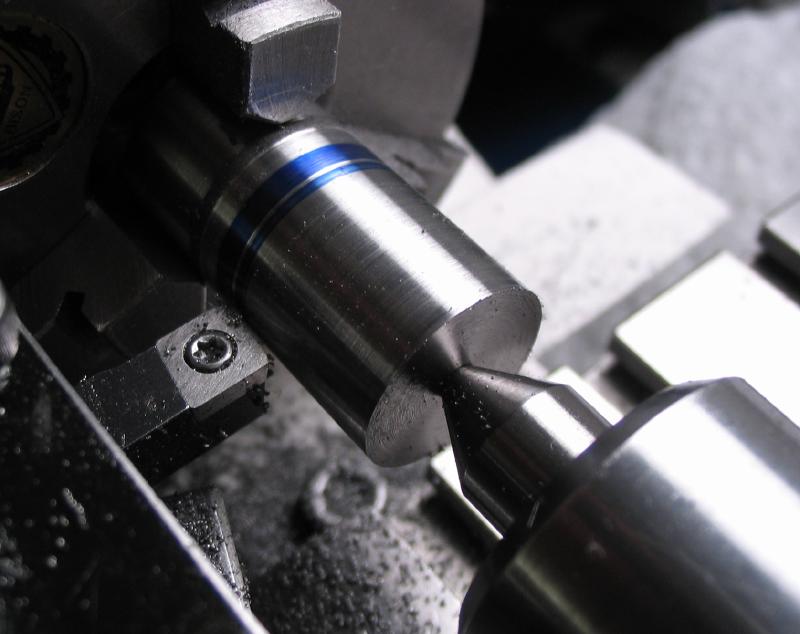
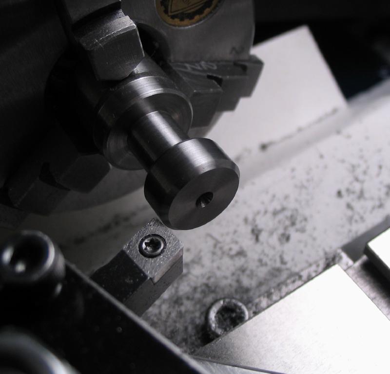
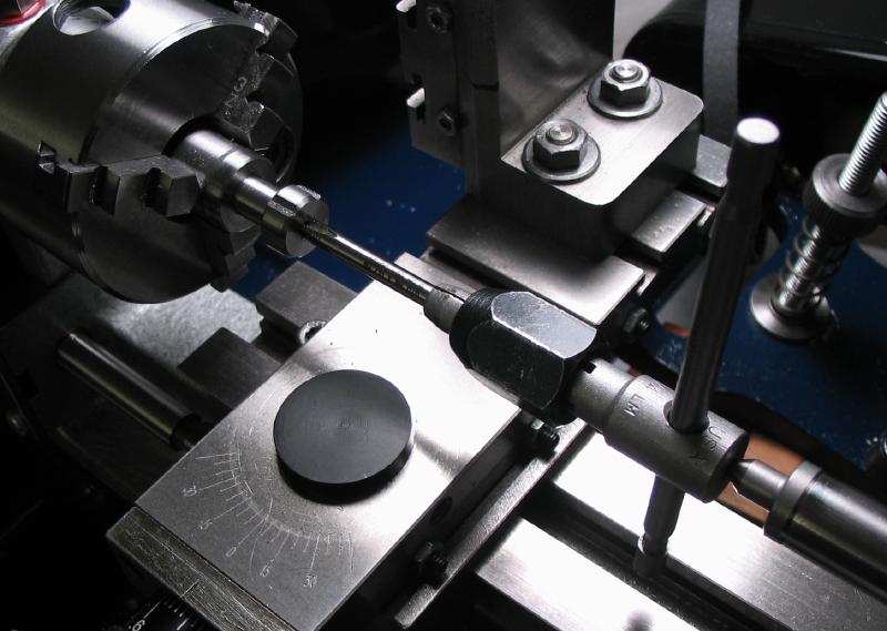
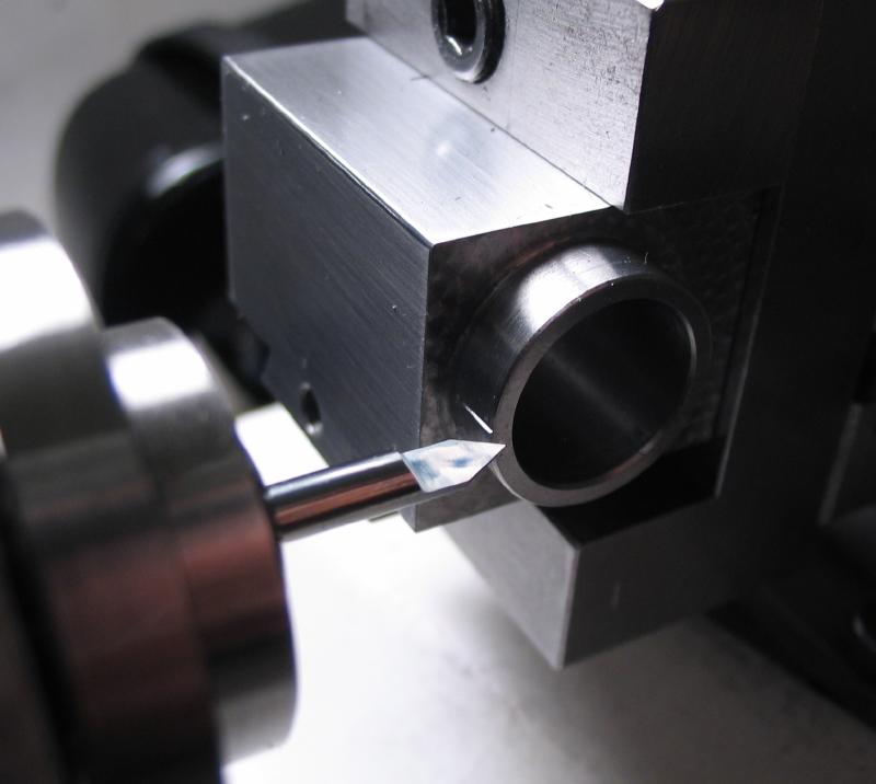
The spindle was pilot drilled 1/8" and then 5.3mm, these were convenient sizes, and ultimately were to permit the use of a 0.180" boring bar. The spindle was bored out to 8mm to accept a B8 collet. The end was bored to a 20 degree taper to also match the collet.
|
|
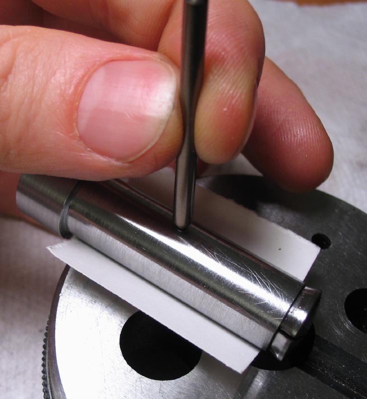
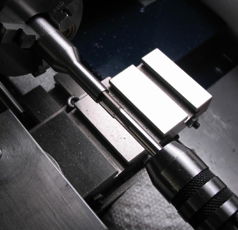
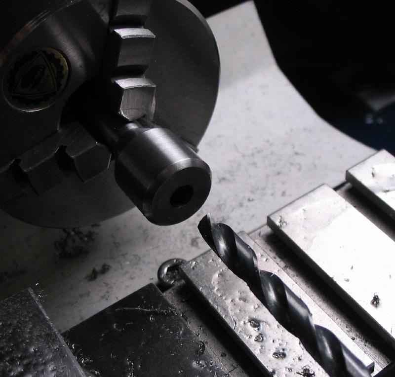
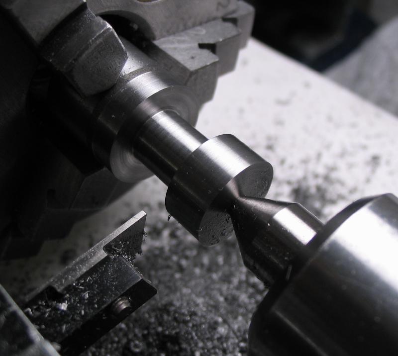
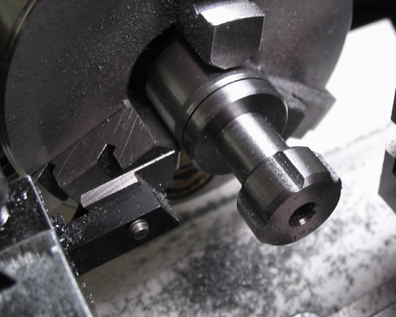
The work was then parted off. The work is reversed in the chuck and was wrapped in cigarette paper to provide some protection from the chuck jaws. The parted face was turned smooth and spot drilled. Again the work was drilled and then bored to pass the draw bar (8.7mm to a depth of 25mm).


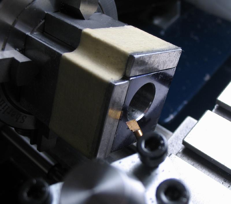
The end was taper bored 30 degree to mate with the drawbar.
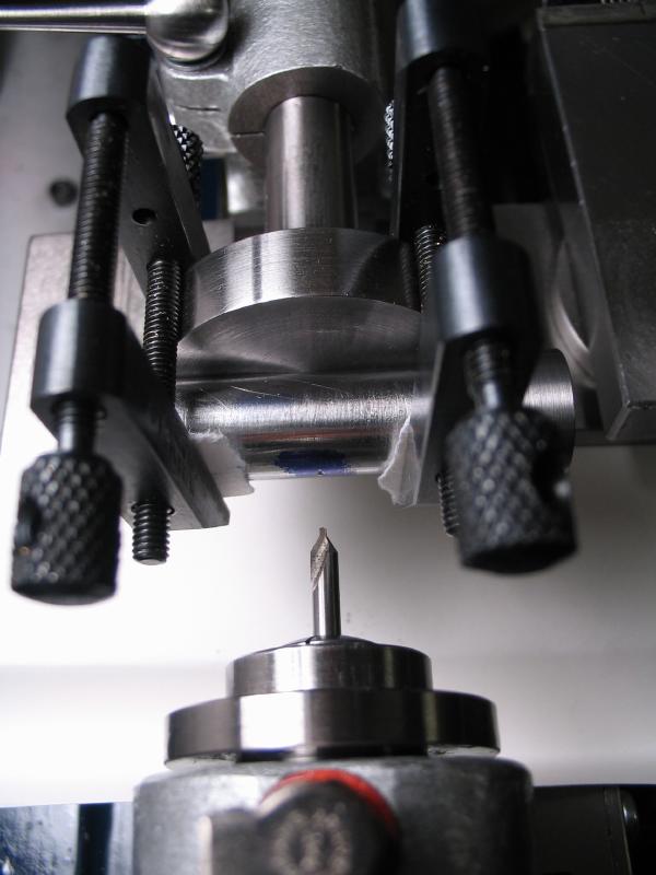
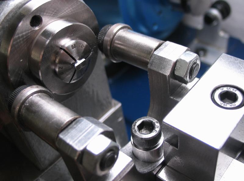
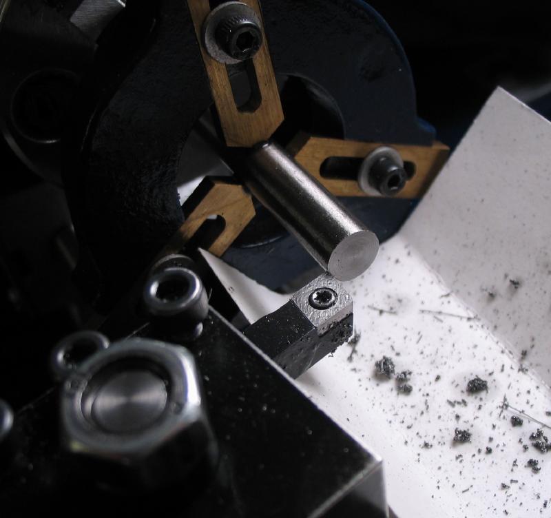
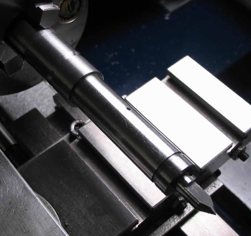
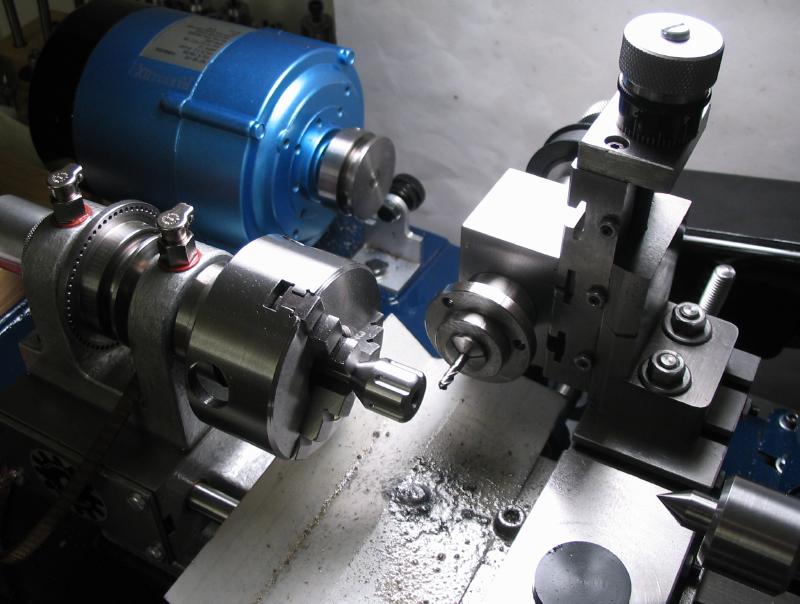
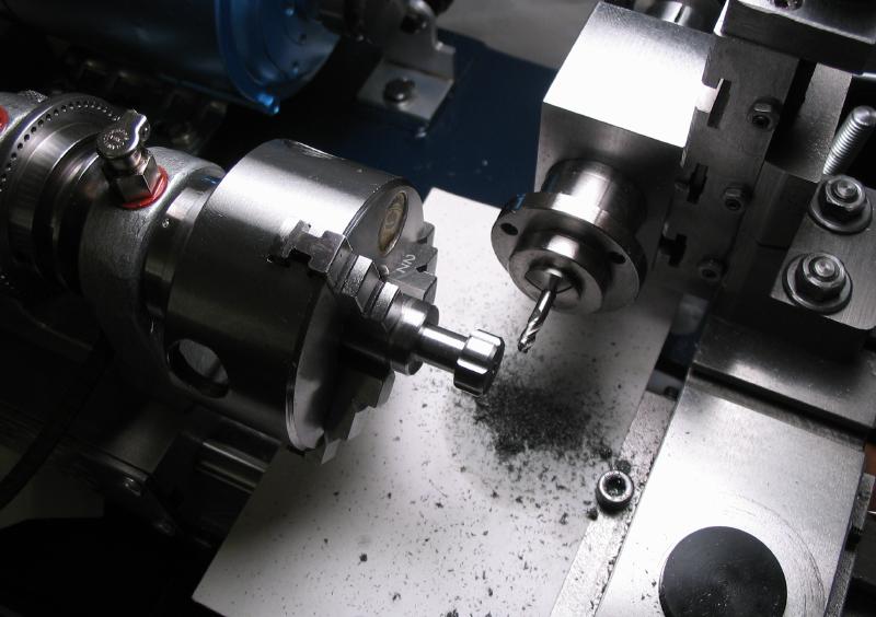
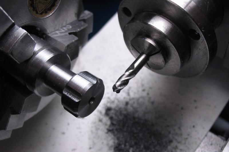
The spindle was mounted on the tailstock drill pad (with vee slot). Toolmaker's clamps assist in holding the work in place. The position for the register key was center drilled.
|

|
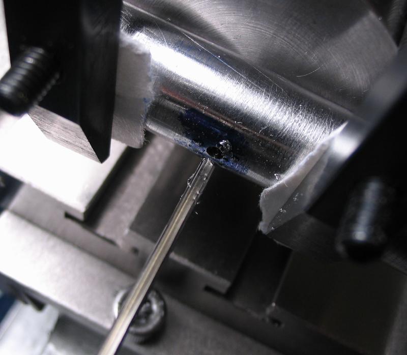
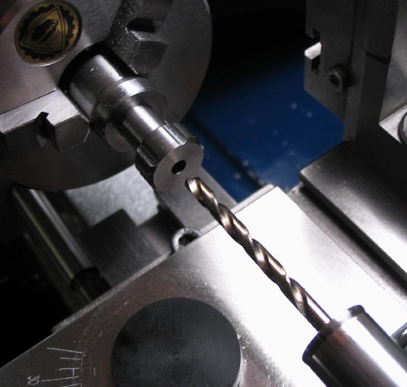
The hole was drilled 1.90mm.

The hole was then opened to 2.00mm with a reamer.
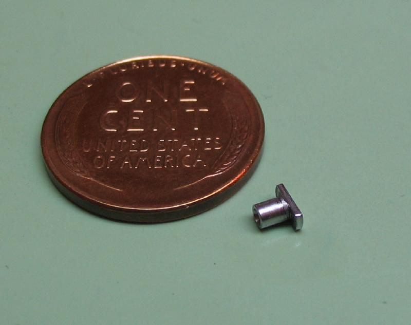
The register key was started from 4mm O-1 drill rod. For a length of 2.4mm the rod was turned down to 2.00mm to snugly fit the hole in the spindle.
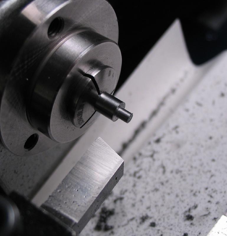
The end was center drilled to provide a rivet surface later on.
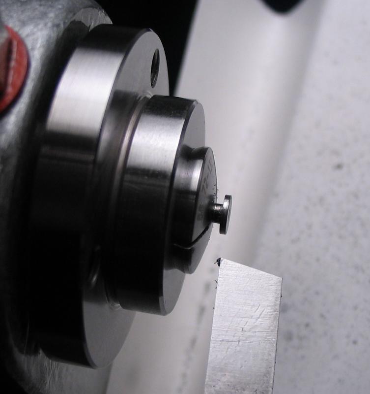
The key was parted off at a thickness of 0.7mm.
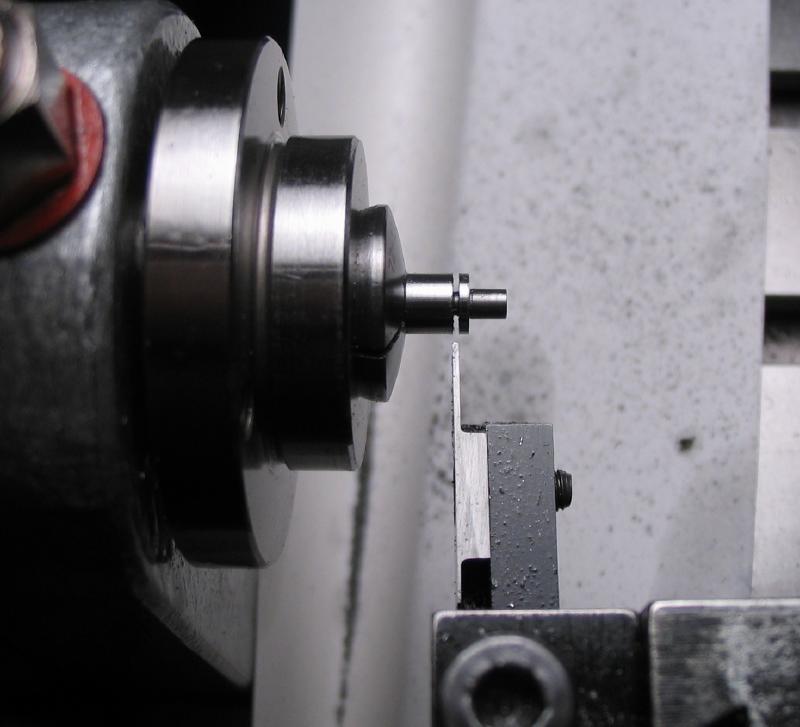
The key is reversed and the parted end faced to a final thickness of 0.5mm to freely fit the depth of the keyway in the collet.
The headstock is locked and the filing rest attached. The key must be reduced evenly on each side by an amount of 1.125mm. This value was determined by measuring the width of the keyway in a collet with feeler gauges (1.80mm) and subtracting for side-shake (0.05mm) = 1.75mm. The starting diameter of the key is 4mm, subtract the desired final width (1.75mm) = 2.25 and divide by two = 1.125. After setting the height of the filing rest rollers to be even with the top of the key flange, the height of the filing rest can be lowered 1.125mm by retracting the cross slide by an amount of 0.65mm (arrived at by multiplying 1.125mm by 0.577 (the tangent of 30°)).
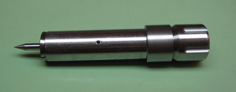
The resulting key can be inserted in the spindle (from the inside). The key is aligned by inserting a collet.
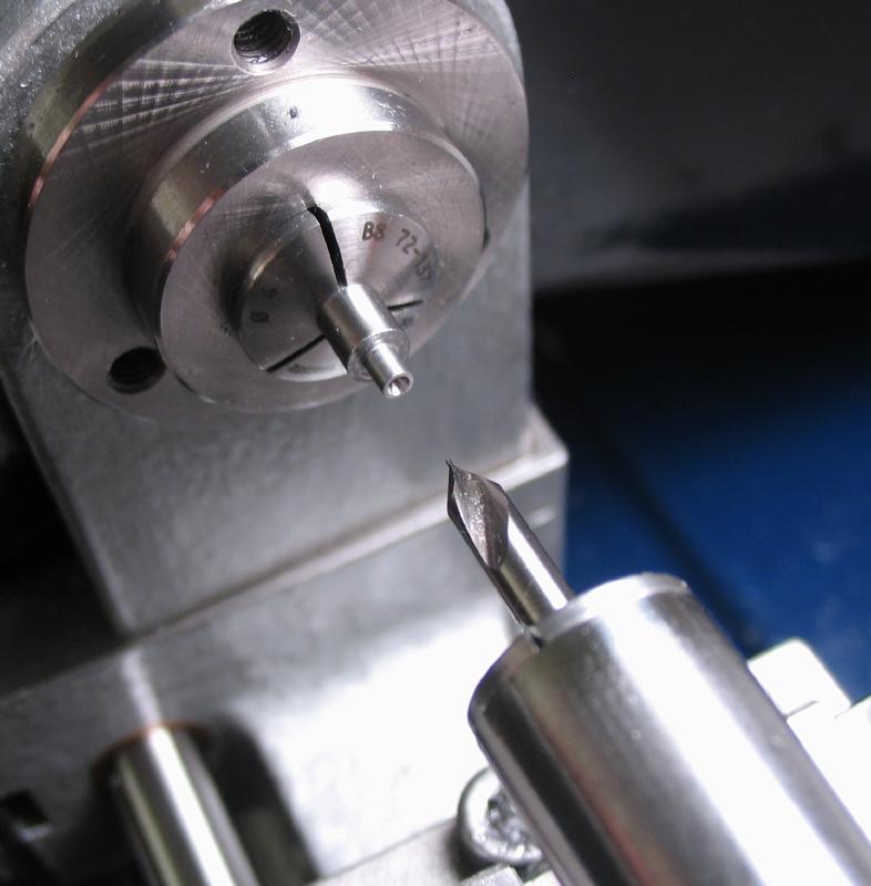
A punch was made from 1/8" O-1 drill rod. It was given a 60 degree point, hardened in oil, and tempered to a straw color.
With the collet in place, the key is fixed using the punch and light taps with a hammer. The key is not completely riveted into place yet.
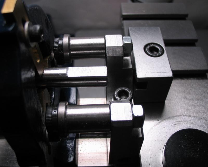
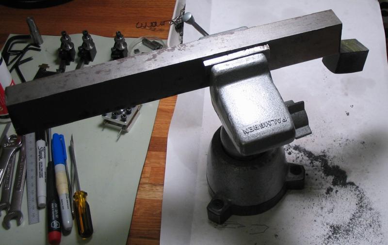
An anvil is made from 8mm O-1 drill rod for riveting the key in place. A flat is filed to fit into the spindle and under the key (with a snug fit).
|
|

The anvil is held in the vise and the spindle slipped on. The key is then hammered with the previously made punch.

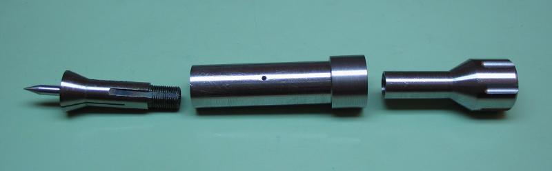
Drawbar
Collets are drawn into the spindle using a drawbar. The work is started from 5/8" 1018 mild steel rod. With center support, the rod is turned down to 8.2mm.
|

|
A taper is turned to match the countersink in the end of the spindle (30 degrees).
The drawbar was drilled 1/8", followed by 5.3mm and then 6.2mm. The latter is for tapping the rod for the collet thread (e.g. B8).

|
|
|
|
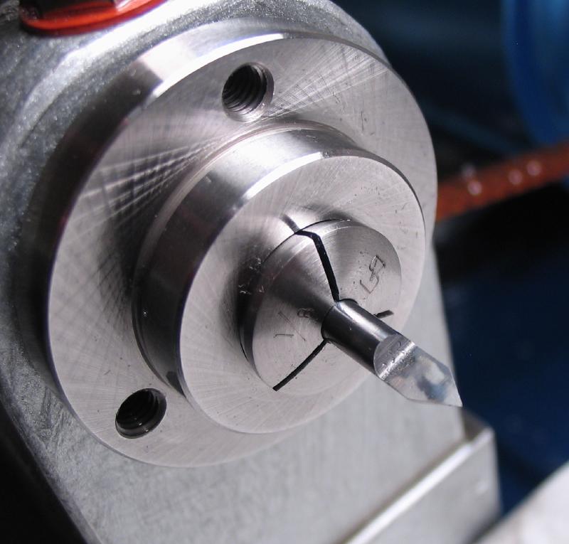
Its function is tested with the spindle in place and a half-center with collet shank.
The work can now be parted off.
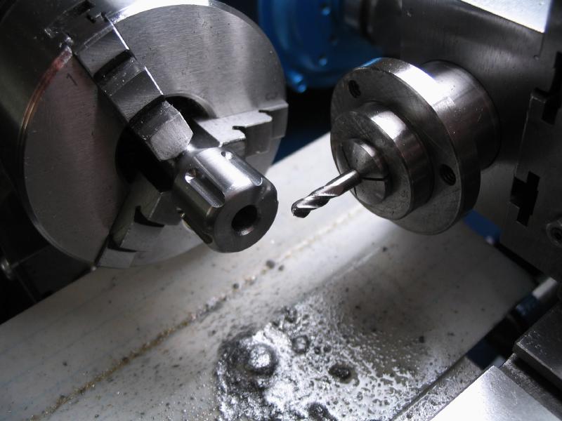
The work is reversed in the chuck. It was then faced and spot drilled. The length was too long to drill through initially, so it was drilled now for the ability to pass stock, tooling etc. that are being held in the collet. It was drilled 5.3mm.

|
|
The drawbar is given a gripping surface using a 1/8" ball-end mill. The mill is held in the wheel and pinion cutter spindle. The headstock is locked and the ball mill fed into the work. Eight grooves were milled to a depth of 1.0mm.
|
|

|
|
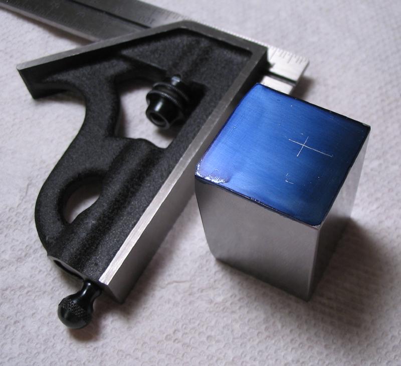
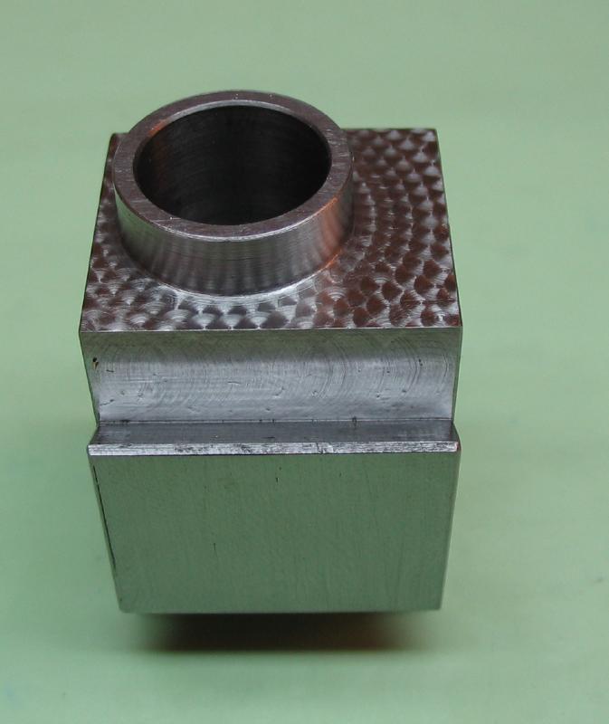
The Tool Block
The main body is started from 1" x 1-1/2" mild steel bar. Some quality time was spent with the hacksaw and a 1" section was parted off.
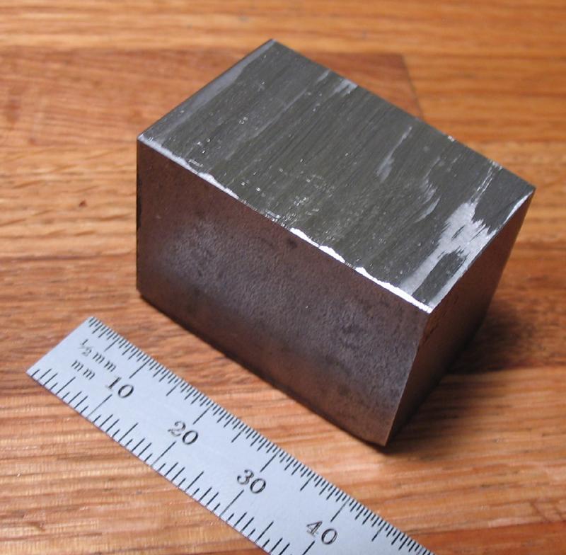
The block was squared up on in the four jaw chuck and a progression of facing cuts were made on opposing sides until all faces were machined. One side was the end of the bar stock which had been significantly chamfered by the metal supplier. This side will be milled away later for the dovetail.
 |
 |
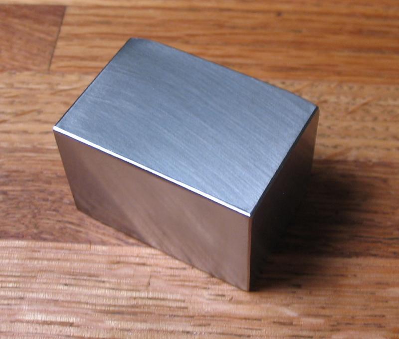
The tool marks were removed by rubbing on 400 grit emery paper fixed to a glass plate.
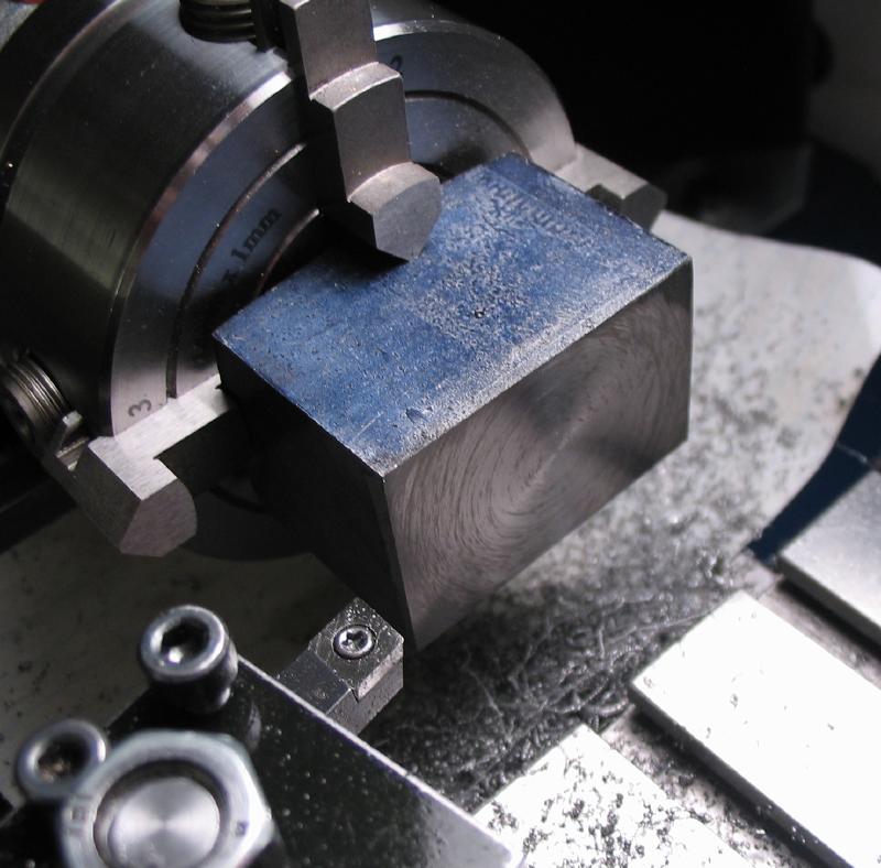
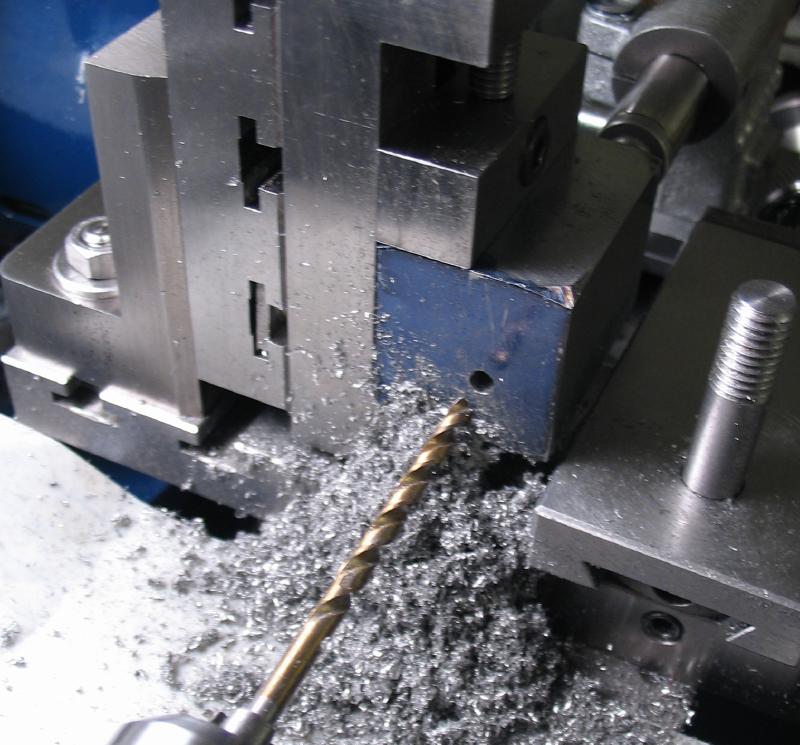
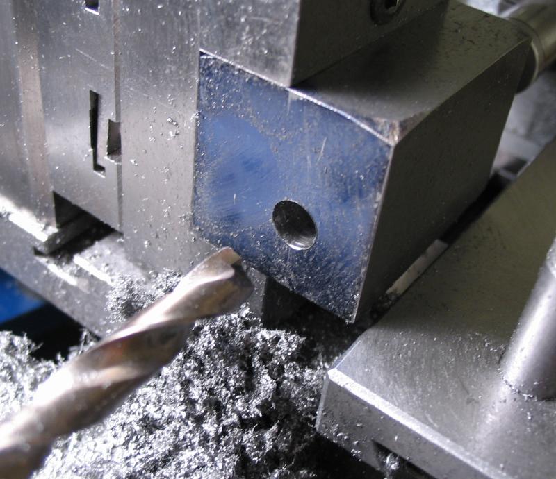
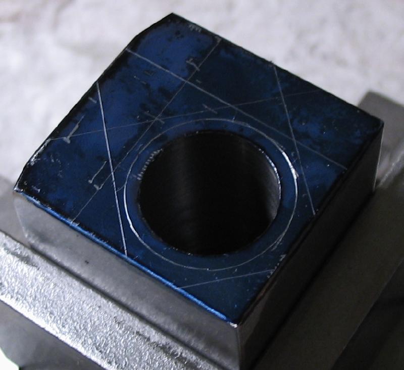
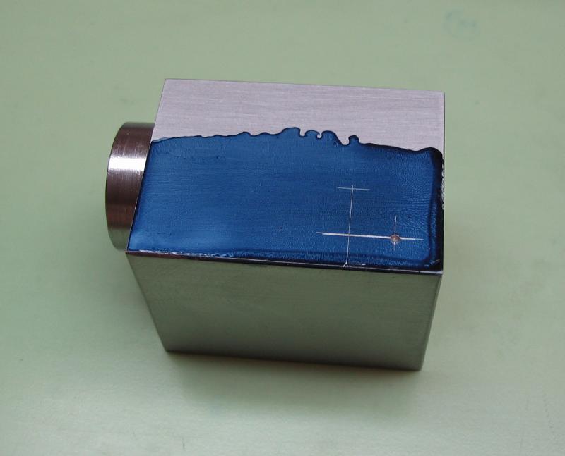
The end face was dyed blue and the position for the collet spindle laid out. This was determined from a quick drawing and was 10mm from each side.
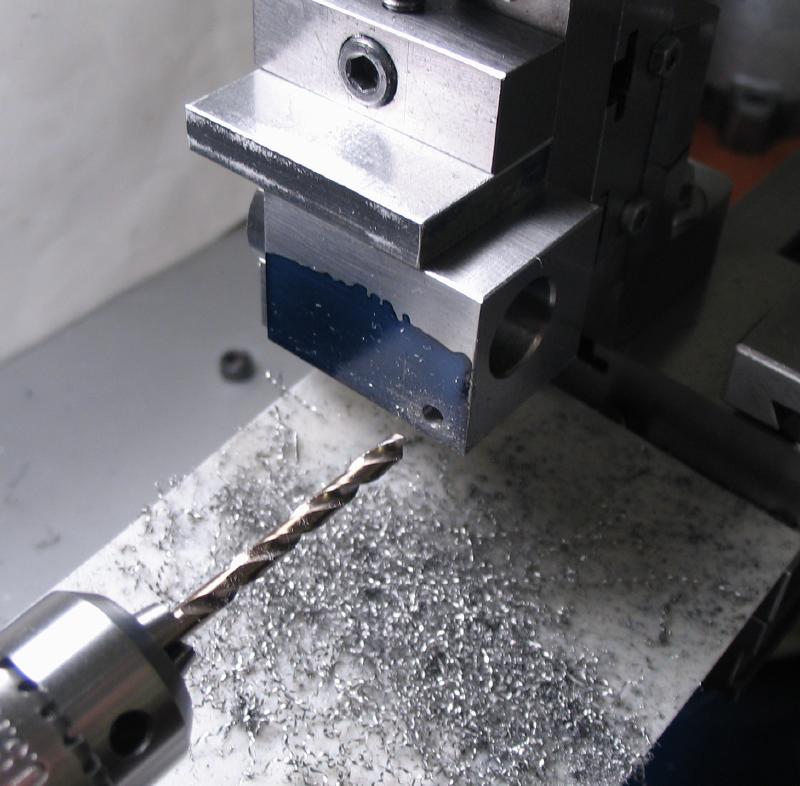
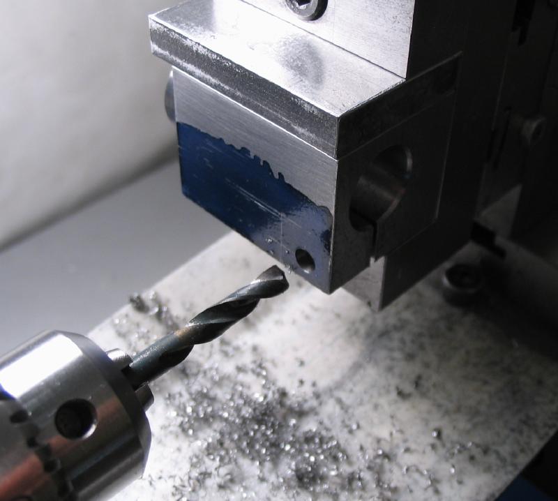
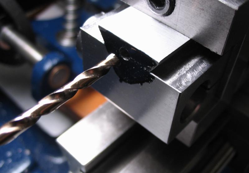
The block was mounted in the machine vice and the position drilled through 1/8" and then 6mm. This happened to be the largest drill on hand. The hole will be bored to its final diameter, but a larger drill would have expedited matters.
 |
 |
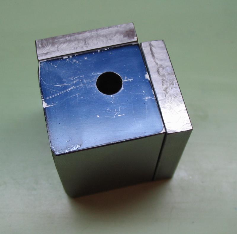
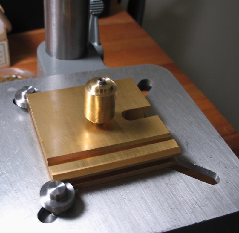
To mount the block in the four jaw chuck, a couple spacers were made from 1" x 1/4" mild steel bar. They were milled flat on each end. They primarily provide a balancing weight to this over-sized job.

|

|
|
|
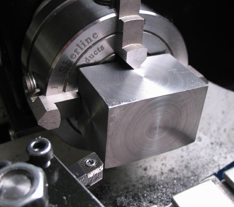
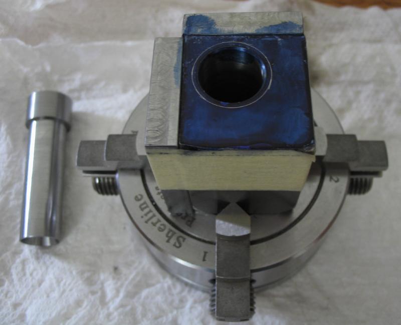
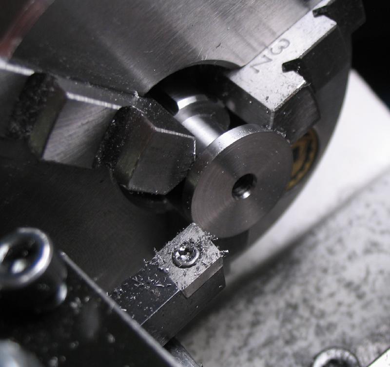
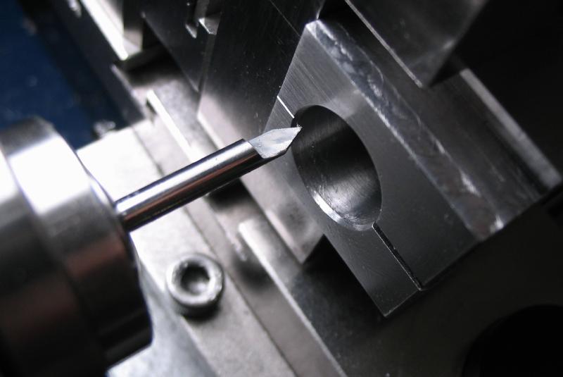
The block was bored to a snug fit with the spindle, which was intended to be 12.7mm.
|

Test fit of spindle
|
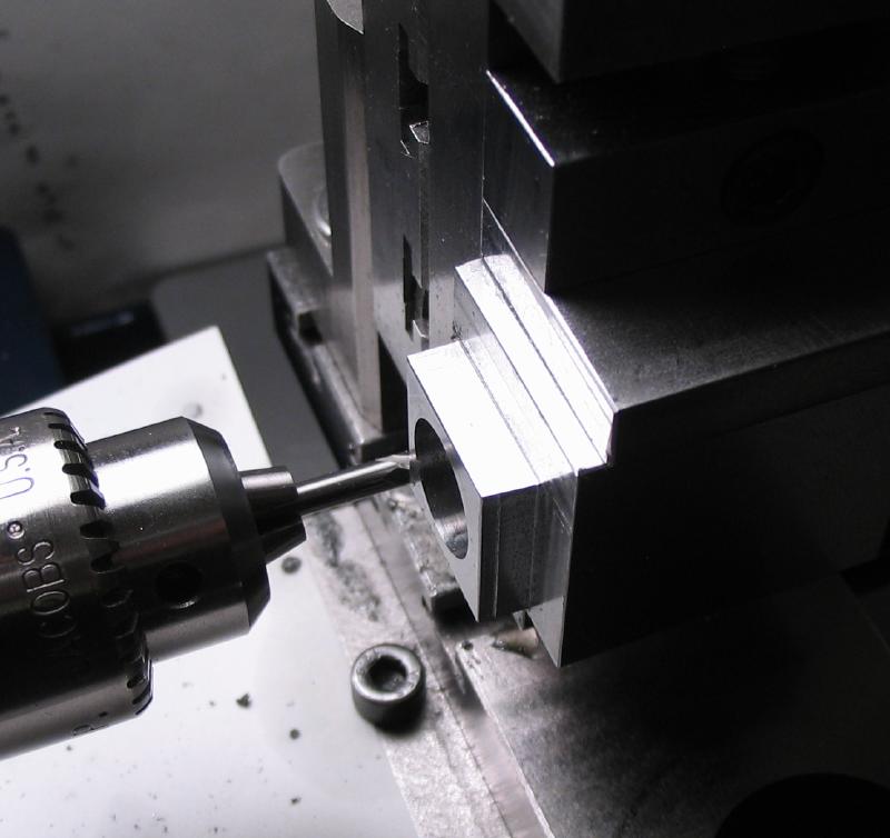
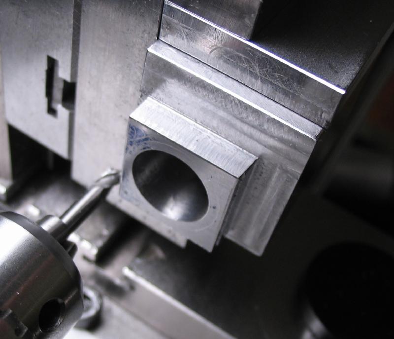
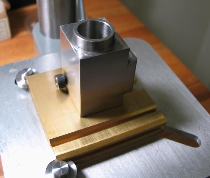
The flange diameter of the spindle was scribed onto the block surface. The block will be turned to form a matching diameter, however, to remove the bulk of the material, it was mounted in the machine vise for milling.
|
|
|
|
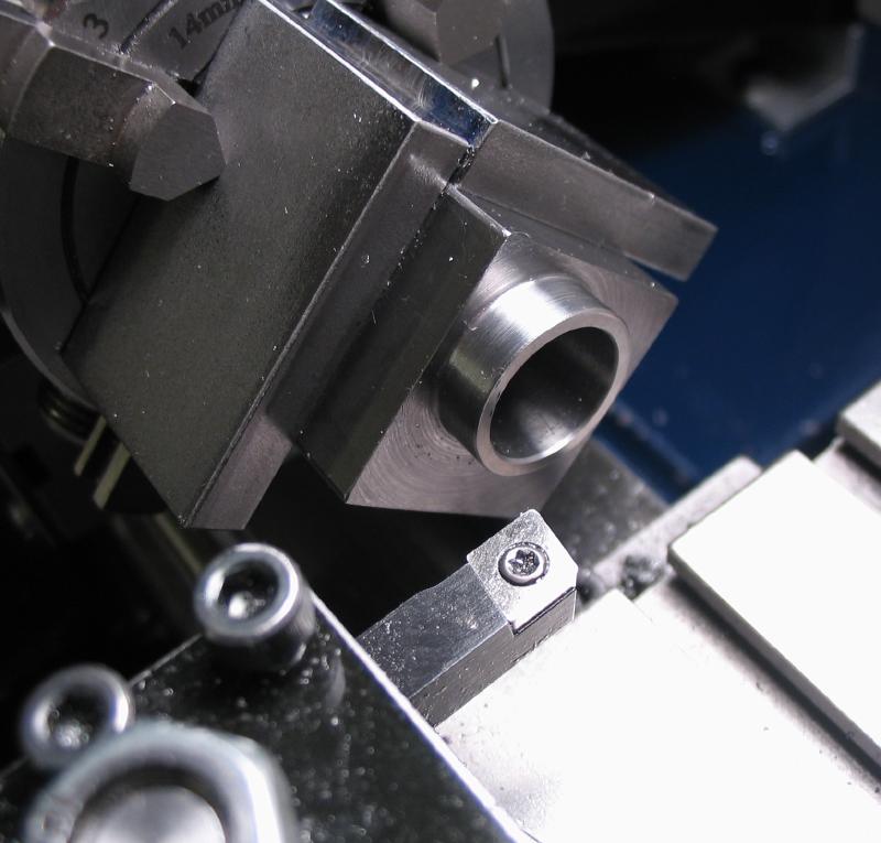
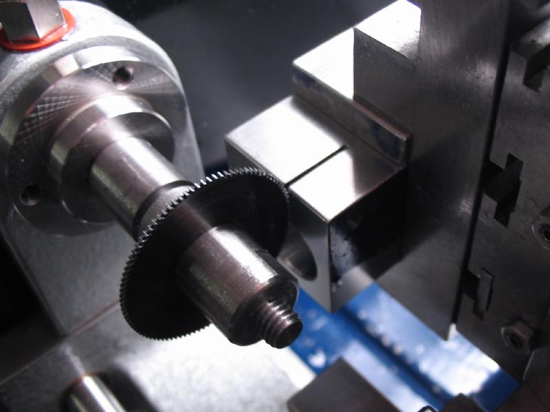
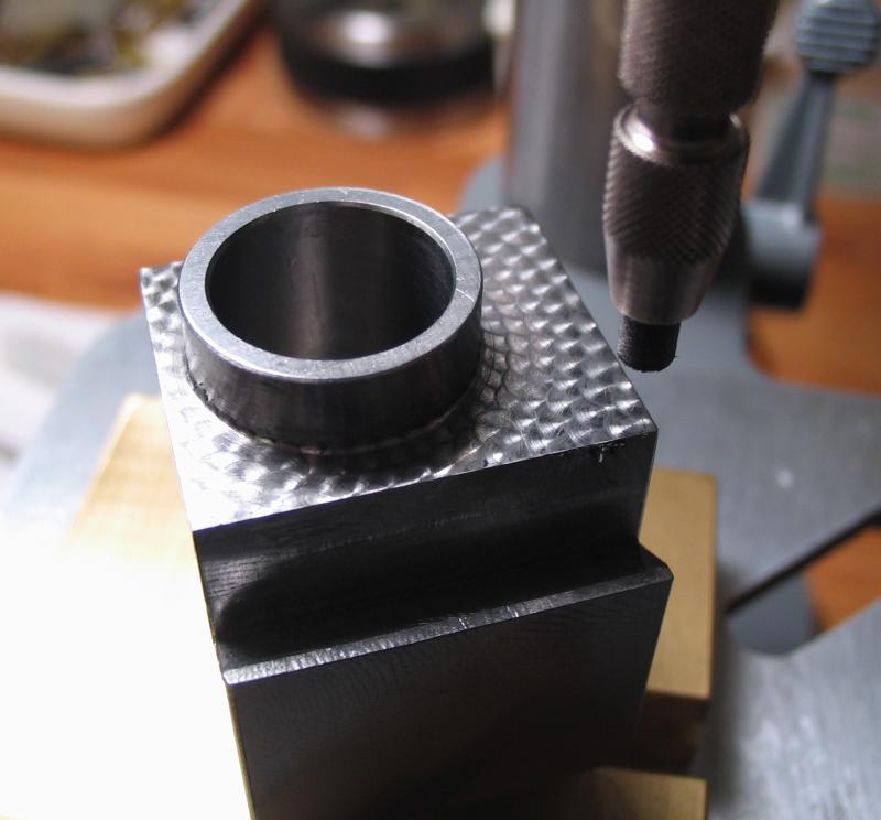
The block was returned to the four-jaw chuck to be turned. The spindle was inserted and used to put on the block on center; a dial indicator was mounted in the toolpost. This turned surface is intended for engraving a witness mark for reference during indexing.

The 'bottom' face needed to be reduced a bit (this could have been done earlier when facing the rough stock, but I decided to keep some room for error.)

The positions for the clamping screw and saw cuts are laid out and center punched.
The screw position was found, chamfered, and drilled 3.3mm (tap-drill for M4x0.7) for a depth of ~22mm.
The bottom is slotted with a 0.8mm saw.
The drilling is opened to 4mm to pass the screw up to the slot.
The 4mm drilling also acts as a tap guide for easy tapping by hand.
The block was then slotted with a 0.014" saw to provide a clamping section.
Both these operations were not photographed due to absent-mindedness.
The dovetail can now be milled.
First the full width (19.1mm) was milled with a 1/4" endmill.
First the full width (19.1mm) was milled with a 1/4" endmill.
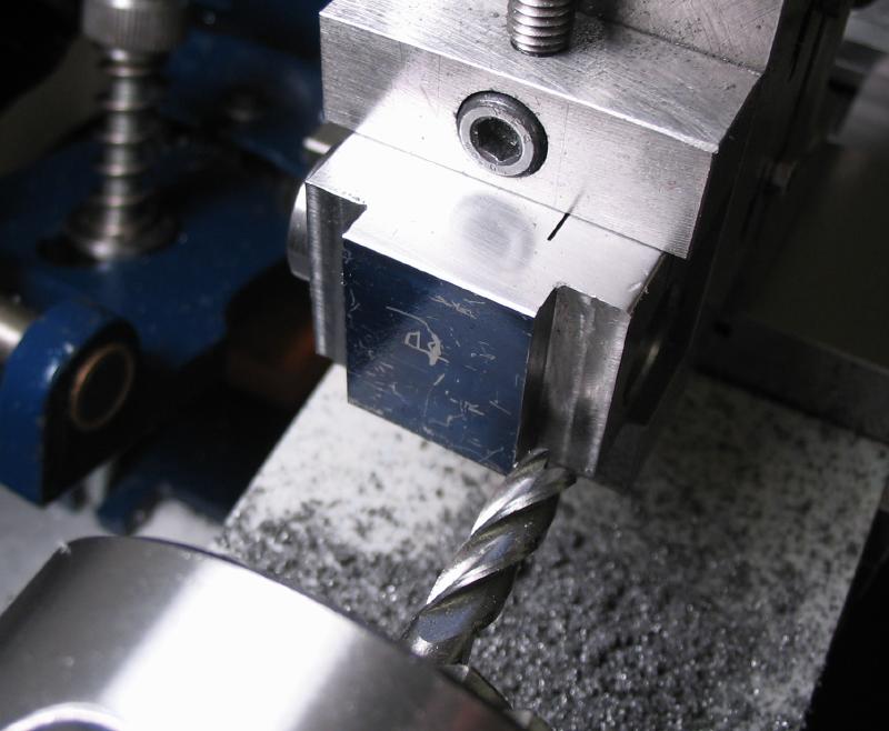
The dovetail is formed with a 60 degree 3/8" dovetail cutter.
The final fit was checked with the recently made tool post clamp.
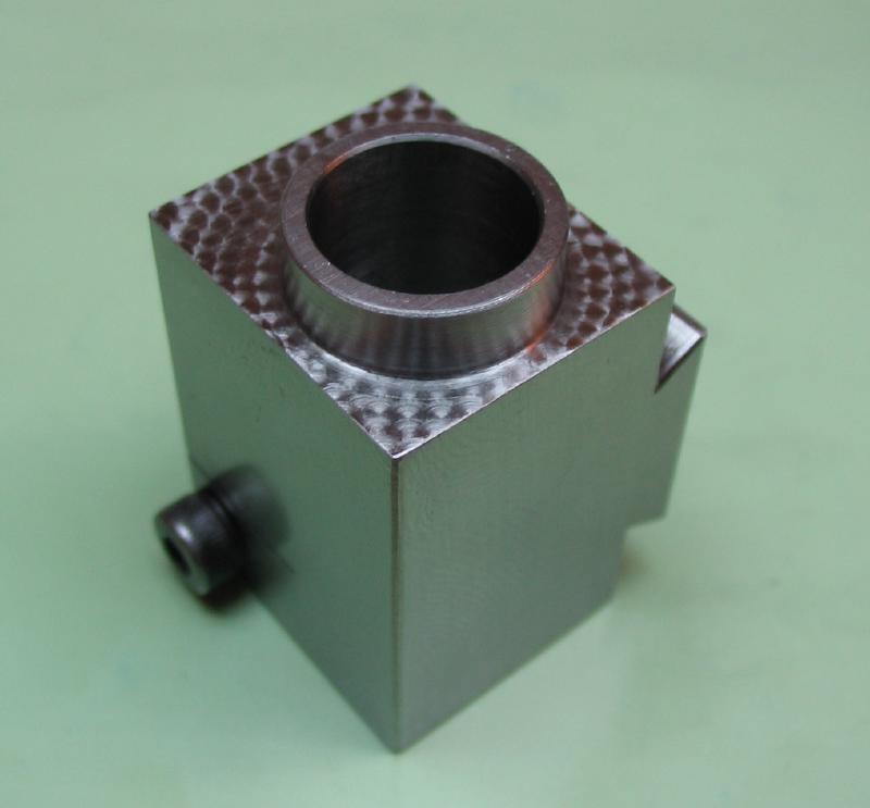
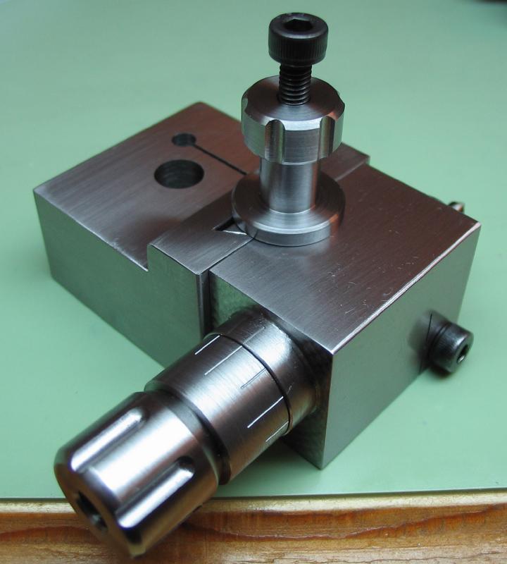
A couple photos of the work at this stage.
'Bottom'
|
'Top'
|

|
|
The back face of the block with the turned portion was tricky to polish. It was coarsely polished with triangular slip stones, but was decided that a another attempt at spot polishing would be tried.
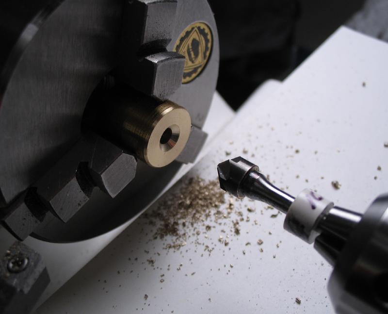
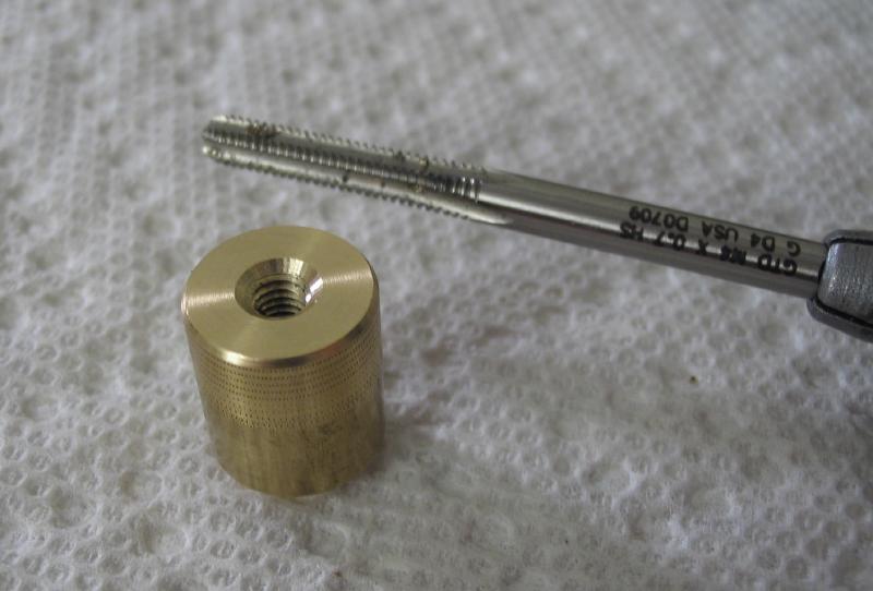
The spindle bore of 1/2" will be used as a pivot point. A bearing was made from a piece of scrap 1/2" brass rod. It was faced, spot drilled, and drilled 3.3mm for tapping M4x0.7. A generous countersink will assist in tapping.
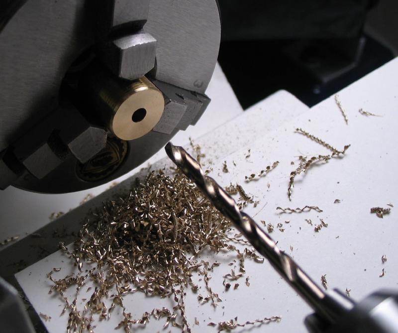
|
|
This bearing can be screwed onto the drill press fingerplate (removing the clamp finger and securing nut).
The block is then slipped onto the bearing and with the plate locked in position, the work can be freely rotated. A 3mm abrasive rod was held in the drill and applied to the surface in an overlapping sequence.
|
|
|
|
The height setting fixture is started from 5/8" mild steel rod. A short length (35mm) was found in the scrap box. I've read many construction articles and frequently note that authors use scrap pieces of metal for their projects. I always wondered where all the scrap came from. Now I find myself saying it...
The rod was faced and turned true for about 10mm. It was reversed in the chuck and again faced and turned true after the end was center drilled for tailstock center support.

|
|
The rod was then turned down to 1/2".
|

|
A waisted portion (8mm diameter) was formed using a 1/32" parting tool.
The corners were chamfered 45 degrees using the compound topslide.
The milling spindle was setup on the vertical slide and with a 1/8" ball end mill, grooves were cut into the flange. The headstock was used to index through six positions.
|
|
The rod is then drilled 3.3mm for tapping M4x0.7.
|
|
The work can finally be parted off.
The parted work is carefully reversed in the chuck and countersunk with a boring bar and faced as well.
|
|
The block is drilled 3.3mm for tapping M4x0.7.
The depth of available threads needs to be about 8mm.

|
|

The stop piece is attached to the block using stock M4x0.7 hardware. A 16mm length set screw and socket head screw were used.

|
|
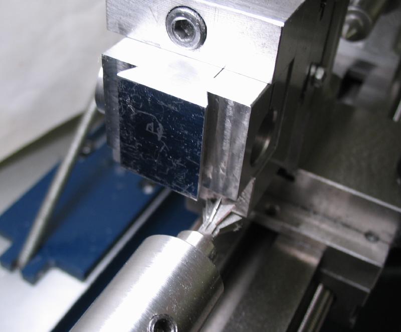
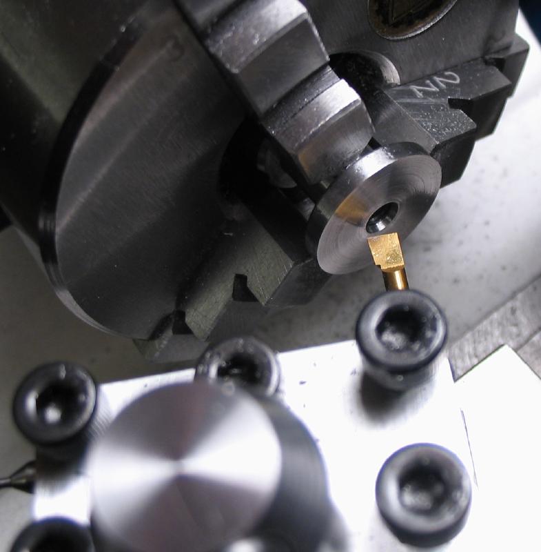
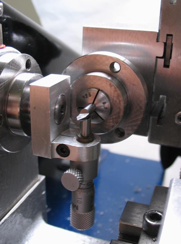
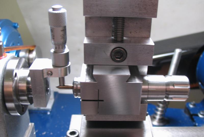
The final step is to engrave the work for indexing purposes. The block was setup in the machine vise, and with the spindle installed, a center was used to bring the flange on center.

A 1/8" engraving bit was run at fairly high speed to make a reference mark.
|
|
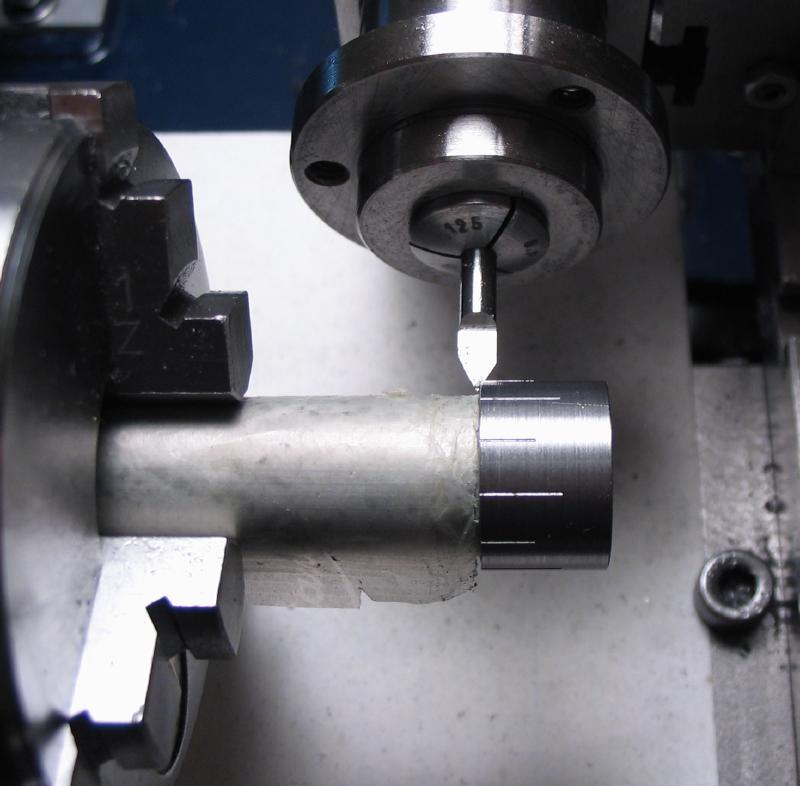
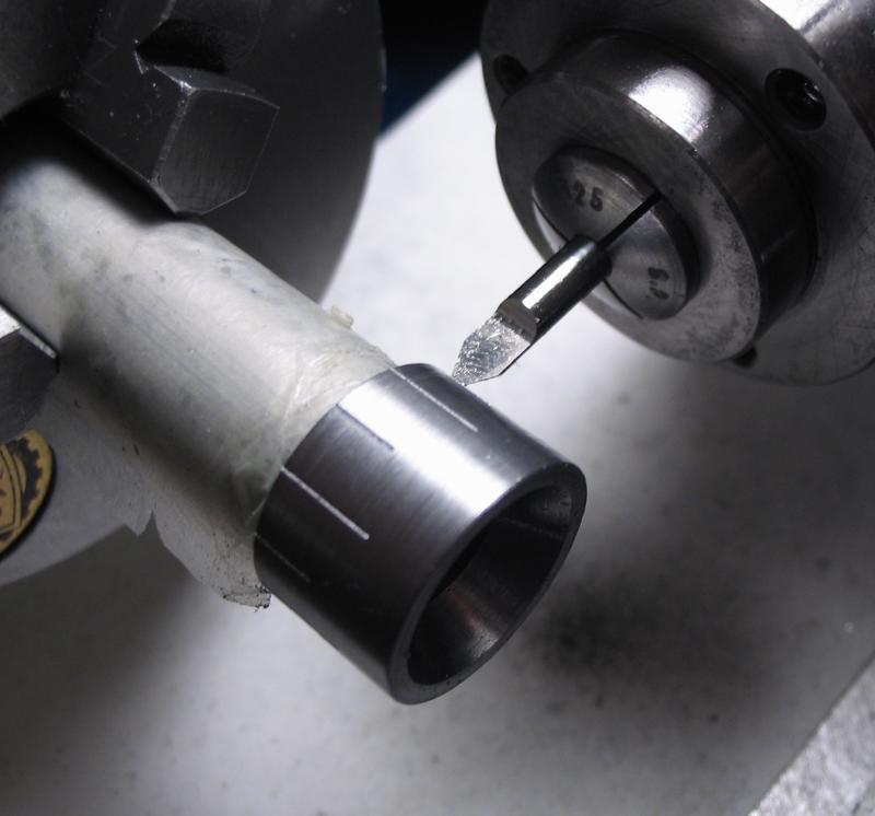
The milling spindle is mounted on the vertical slide and the engraving bit installed. The micrometer centering tool is used to center the cutter.
The tool spindle was mounted in the 3-jaw chuck and 12 marks were made, alternating the length for convenience.
|
|
The block is returned to the vice to make a mark on the reverse face. This is to allow the spindle to be reversed in the block and still make use of indexing. The spindle is installed and used to center the work. The engraving cutter is used to make a groove.
|
|
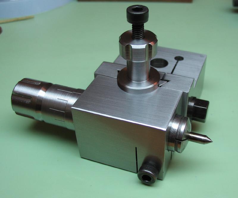
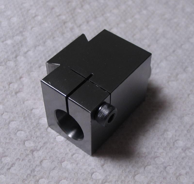
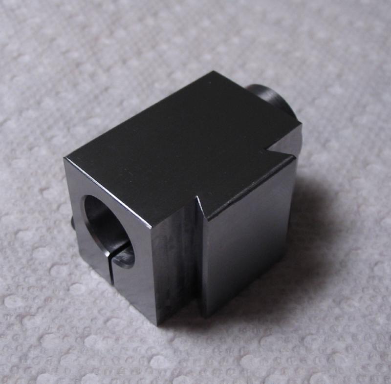
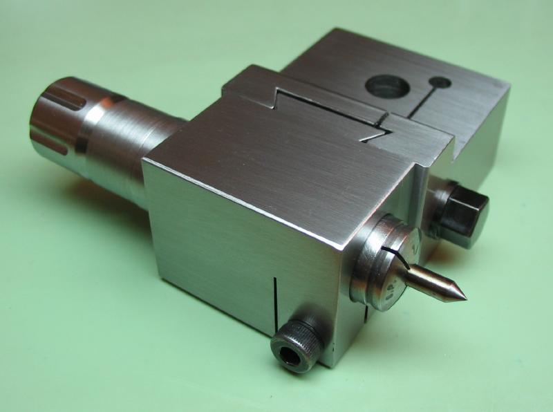
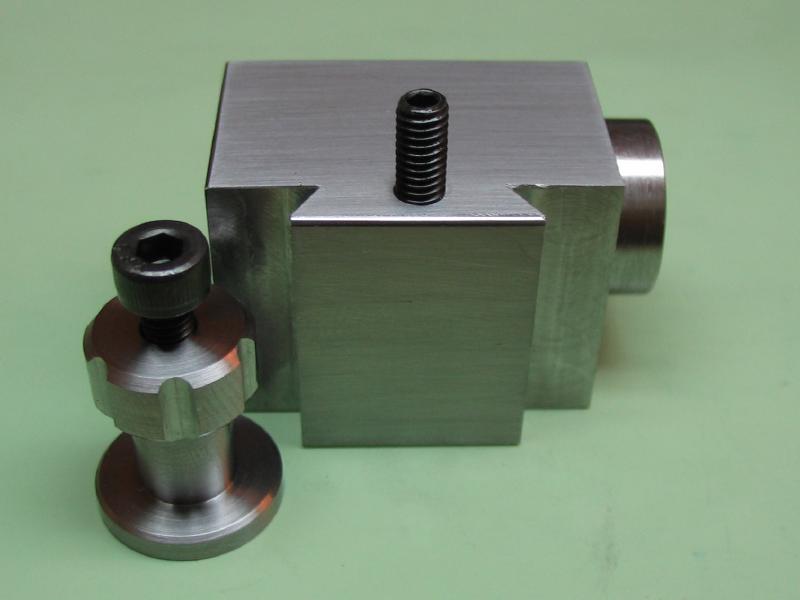
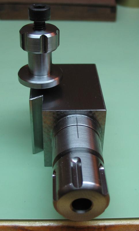
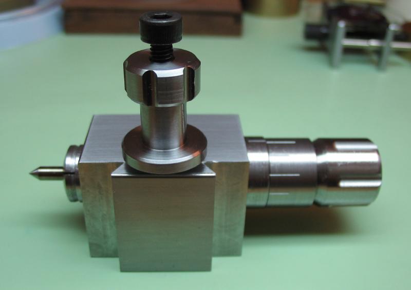
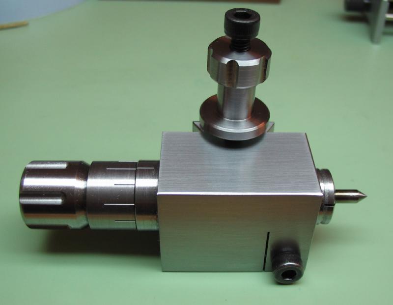
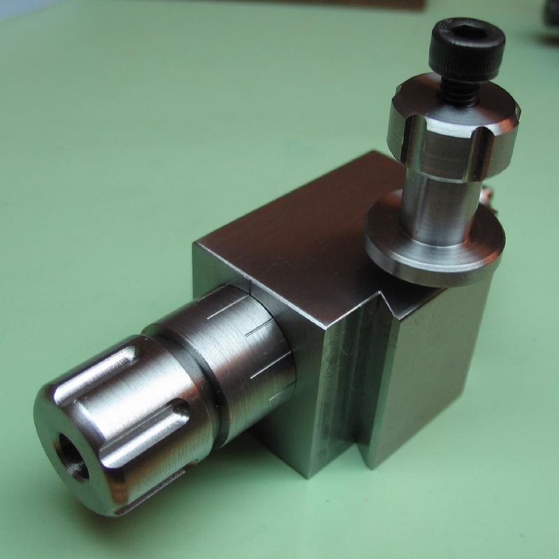
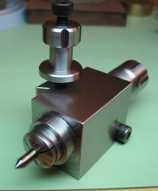
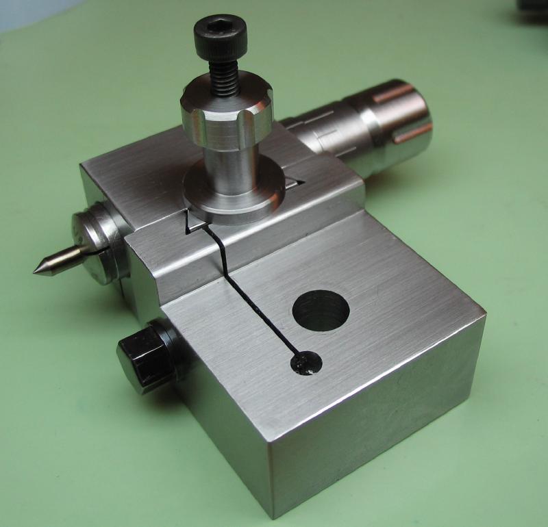
Some gratutious photography of the completed work.
|

|
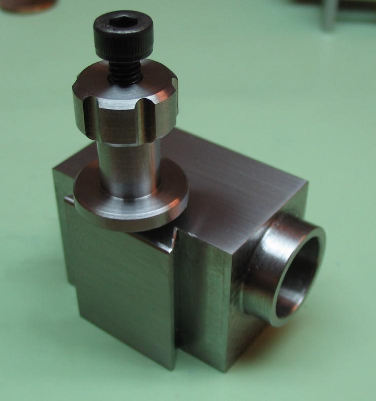
With the spindle reversed.
|
|
The block mounted in the tool post clamp.
|
|