Mini Vice
When filing small parts it is convenient to hold the work in a vice, and small work is often best held in a small vice. Various devices are available for this purpose, but I ran across the plans for a small vice in an article by Bob Loader that appeared in the March 2006 issue (№ 113) of Model Engineers' Workshop magazine. Since the plans were in metric and made to a desirable size, I am following his plans unaltered, and therefore have not reproduced them. The reader will have to follow along without a drawing, but the plans are relatively simple.
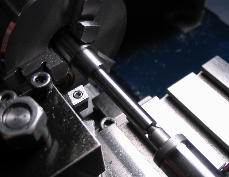
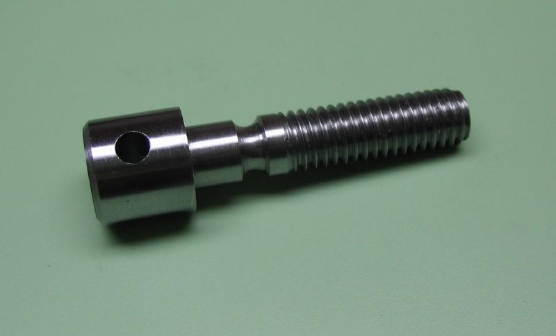
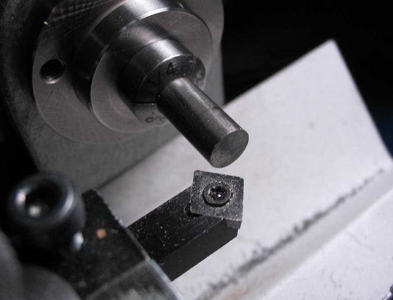
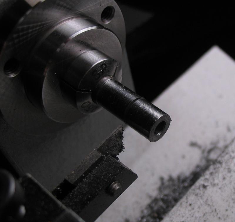
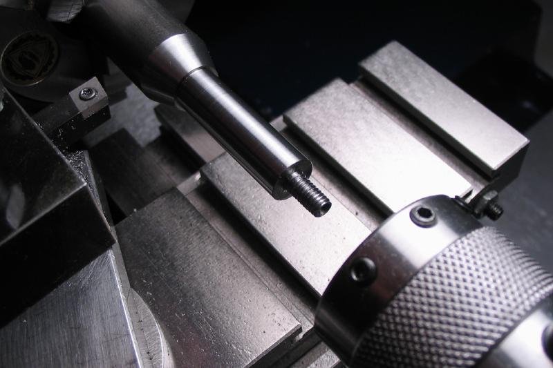
The adjusting screw was started first. One-half inch 12L14 mild steel rod was center drilled, and with tailstock center support, the rod was turned to 10mm in diameter for about 40mm. This was followed by turning to 6mm for 30mm of length. This portion was then threaded M6x1.0 for a length of 20mm.
|
|
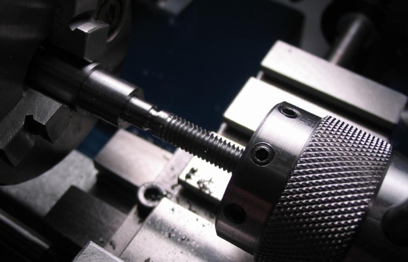
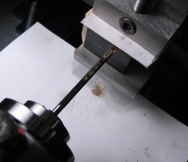
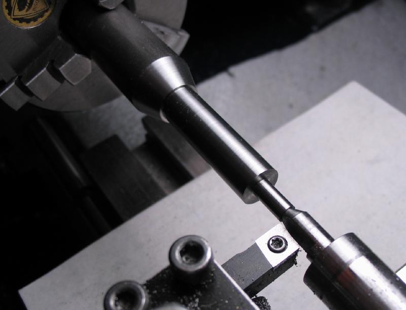
A 2mm wide groove was turned into the rod at about 23mm from the end using a parting tool to a depth of about 0.7mm. This groove was rounded out using a round needle file. The purpose of this groove is to accommodate a 2mm retaining pin. Mr. Loader suggested making a custom parting tool to perform this task, and this would be advisable for more precise work, as my crude approach likely took longer anyway!
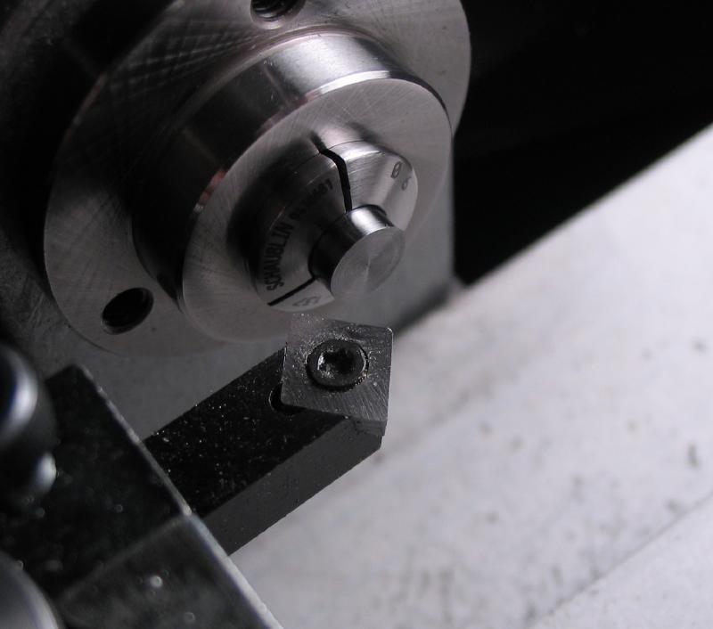
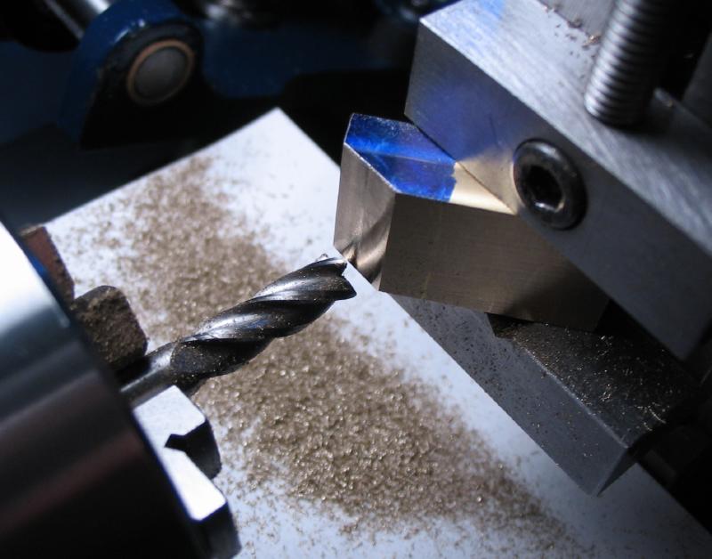
The screw can be parted off the rod, giving a head length of 10mm. The work is reversed in the chuck, chamfered 45 degrees to remove the sharp edge, and then cross drilled 3mm for a tommy bar.
|
|
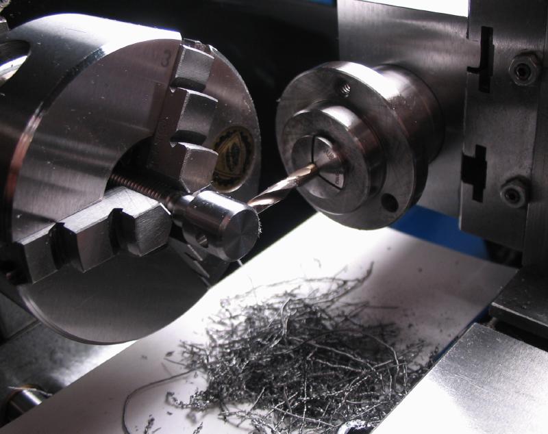
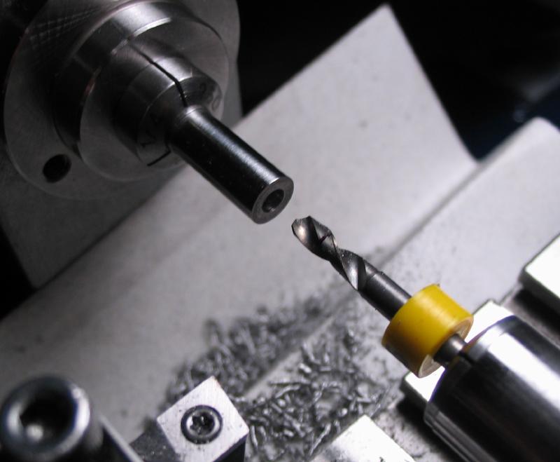
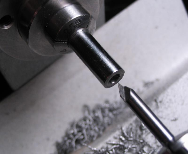
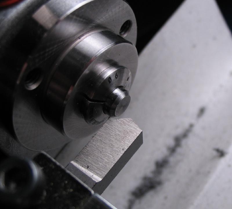
The tommy bar is made from a piece of 3mm drill rod, and endcaps made from 1/4" mild steel (12L14). The rod was turned to 6mm for a length of about 13mm. The end was faced, drilled 2.95mm to a depth of 4mm, and lightly countersunk and chamfered to remove sharp edges. The work is parted off at 6mm in length.
|
|
|
|
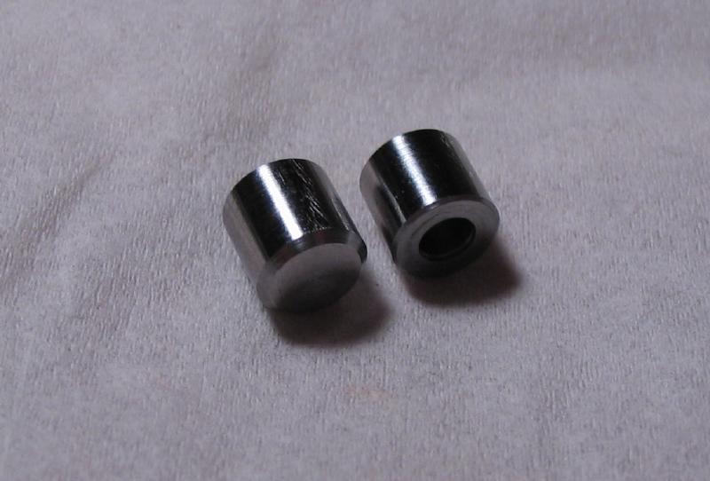
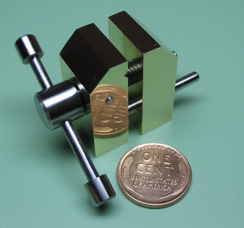
The work is reversed into a 6mm collet and faced and chamfered 45 degrees with a form tool. The tommy bar is inserted into the adjusting screw and the endcaps were tapped on with a small hammer.
|
|
|

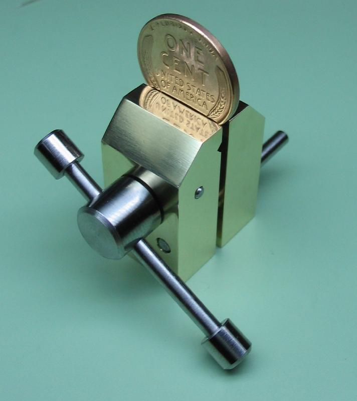
Mr. Loader used tool steel for the jaws of the vice, and concludes that any material will suffice. He specifies it as W.Y.H. (i.e. "what you have"). Since the vice is intended for delicate work and since I happen to have suitable sized stock on hand, I decided to make the jaws from brass. Brass will be less durable, but less likely to scratch or otherwise mar the work being held.
5/8" x 1.25" brass bar was sawn off in two sections of slightly greater than 10mm in width. These were then separately faced to 10mm in width by mounting in the machine vice and milling with a 1/4" endmill. They are then kept together and faced on the remaining sides to square things up and bring to final dimensions (each jaw, 10 x 30 x 16mm). These dimensions deviate slightly from the plans in the MEW article (i.e. 10 x 27 x 15), but made use of the extra material in the closest stock I had on hand.
The jaws were scribed using the 45° portion of a combination square, and separately mounted in machine vice and the top edge milled at an angle of 45°. The angle does not need to be precise and is simply to provide some clearance during use.

|
|
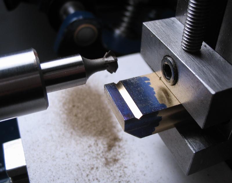
One of the jaws was remounted in the vice and setup for milling a vee channel for holding round work. The 90° channel is about 4mm from the top edge and to a depth of about 1.2mm.
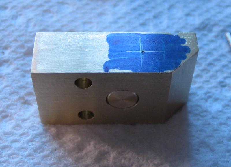
With most of the milling finished, the jaws are mounted together for drilling and reaming two 3mm holes for the guide rods. These were laid out at 9mm from the bottom and 3mm from the edges. The center punch mark was used to center it on the lathe, and the work then spot drilled, drilled 2.9mm, and reamed 3mm just until the reamer breaks through (this was measured since the rear is not in view). The idea being to leave enough material to hold the 3mm guide pin in place in the traveling jaw.
|
|
|
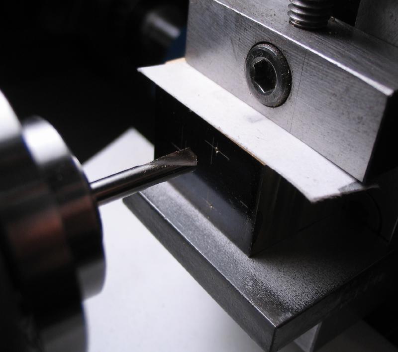
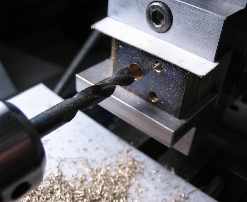
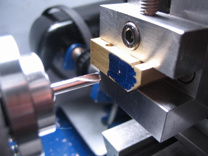
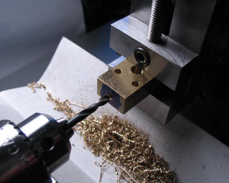
A piece of 3mm drill (happens to have a point) was inserted into a guide pin hole to maintain alignment and the work was repositioned to be in the center of the vise to allow clearance for the drill bit. The screw position is on the center line of the jaw and at 16mm from the bottom. Both jaws are drilled 5mm. The rear jaw will be tapped and the front jaw is opened to 6mm in diameter by drilling to clear the adjusting screw but provide a good fit.
|
|
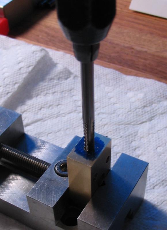
The rear jaw was tapped M6x1.0

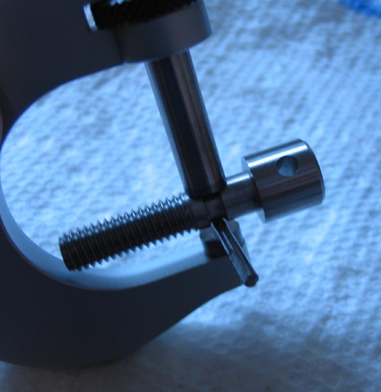
The adjusting screw and a piece of 2mm drill rod were aligned and measured with a micrometer to determine the offset needed for the pin in the jaw. A length of 1/4" brass rod was turned to 6mm and parted off. This brass plug can be placed into the front jaw for drilling the securing pin position. The brass plug is sacrificial and to keep the drill from wandering.
|

|
|
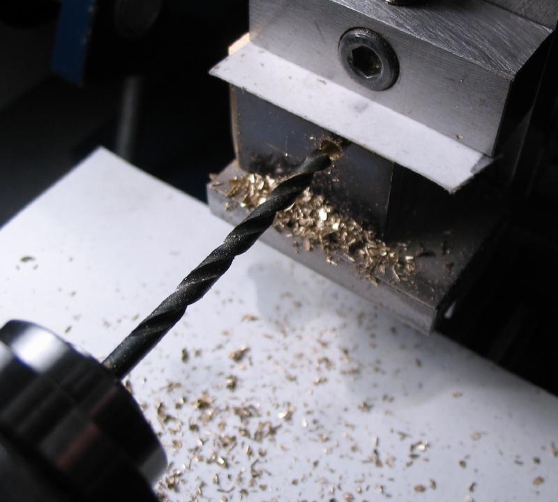
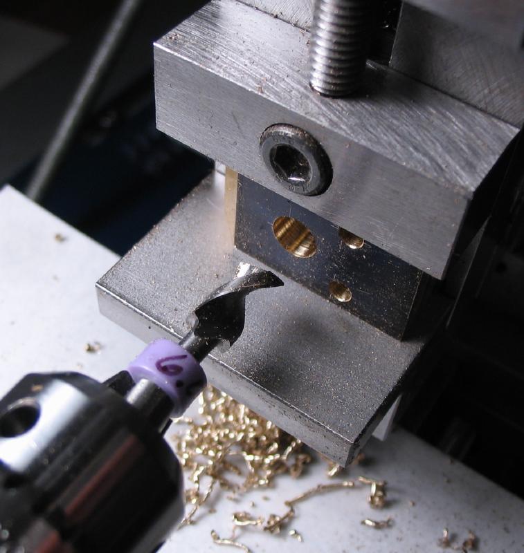
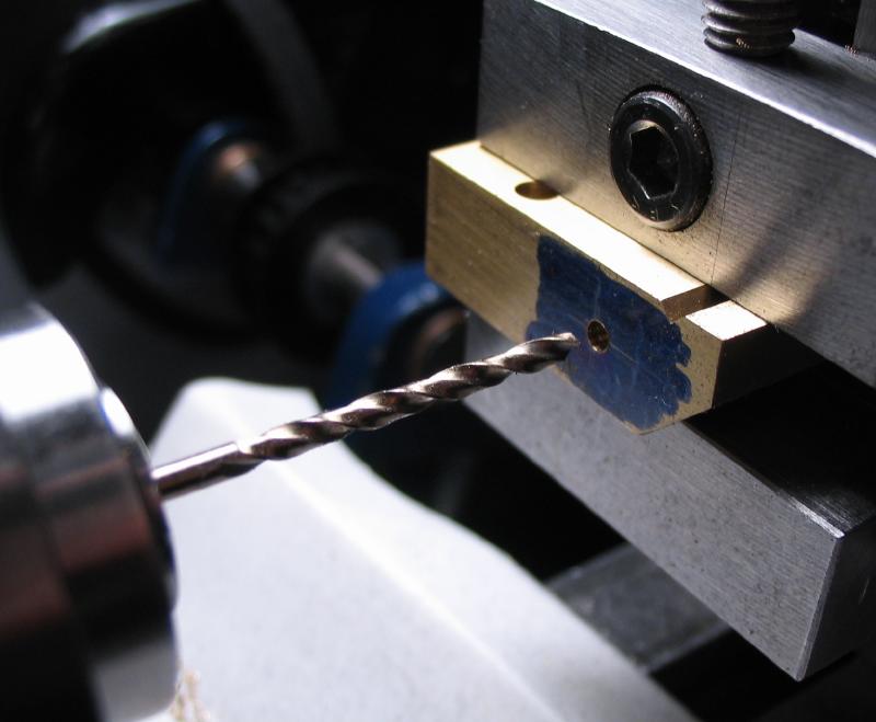
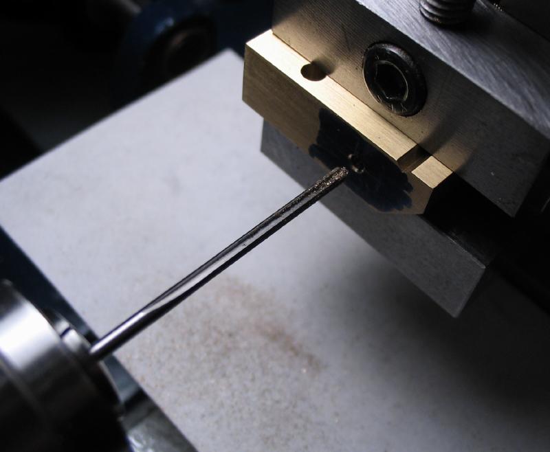
The jaw is returned to the machine vise and aligned to the center of the vise for drill clearance. It was drilled 1.9mm and reamed 2mm.
|
|
|
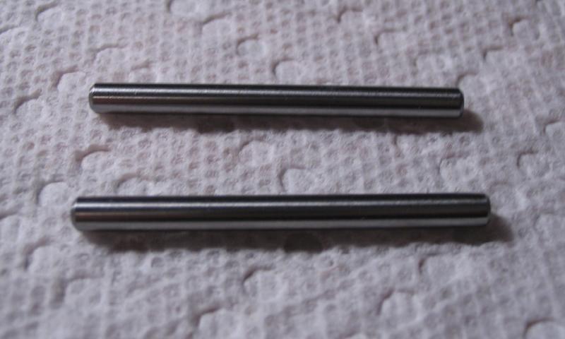
Guide pins are made from 3mm drill rod, chamfered on the ends.
A temporary 2mm pin was fit to test the parts together at this point. The pin is marked for length and sawn. The adjusting screw does not meet flush to the jaw, the retainer pin position must have been drilled slightly off. A washer can be made to fill the space, however the vise still functions as desired.
|
|
The rear jaw was setup on the lathe for drilling 3.3mm to a depth of about 8 to 9mm, centrally located on the bottom. This was then tapped M4x0.7 (finishing with a bottoming tap) to accept the post (made below).
|
|
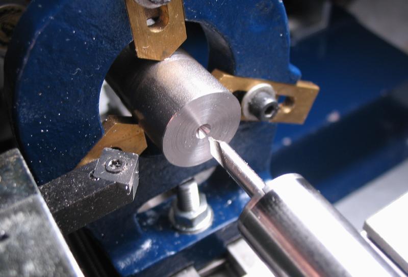
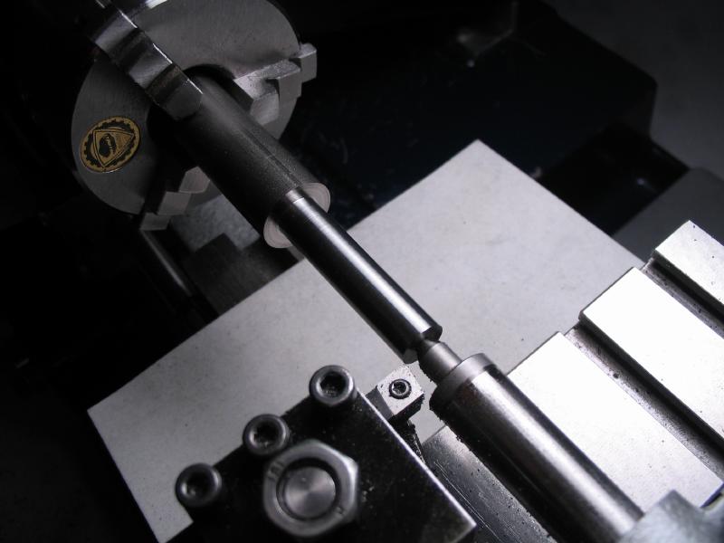
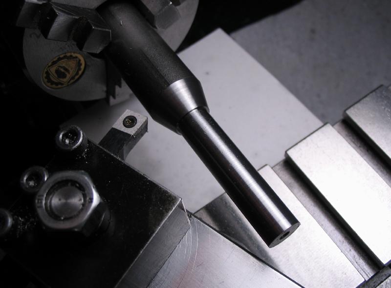
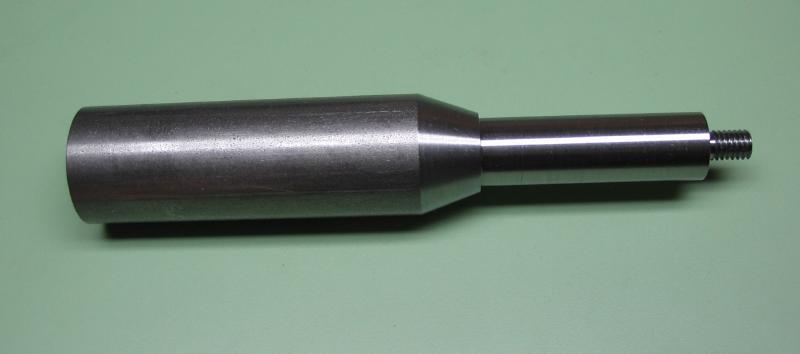
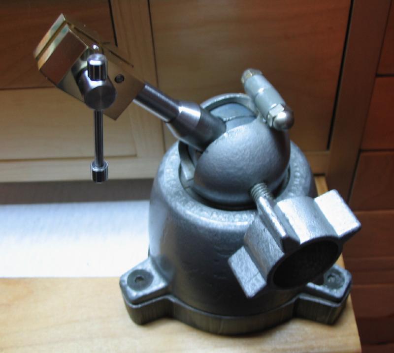
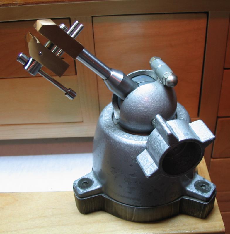
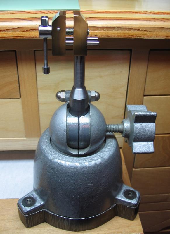
The vise will mount onto a post. I made a post that will fit into the swivel base of another small vise I use. It is a Palmgren vise, and the same basic model is sold under the name Panavise now. The base accepts a 5/8" rod. The work was started with a 90mm length of 5/8" 12L14 steel rod. Both ends were faced using the steady rest, and then center drilled. With tailstock center support, about 37mm was turned to 9mm in diameter, and a 20 degree chamfer added. About 8mm was threaded M4x0.7, and the end 2mm parted off as waste (to remove the center cone).
|
|
|
|
|
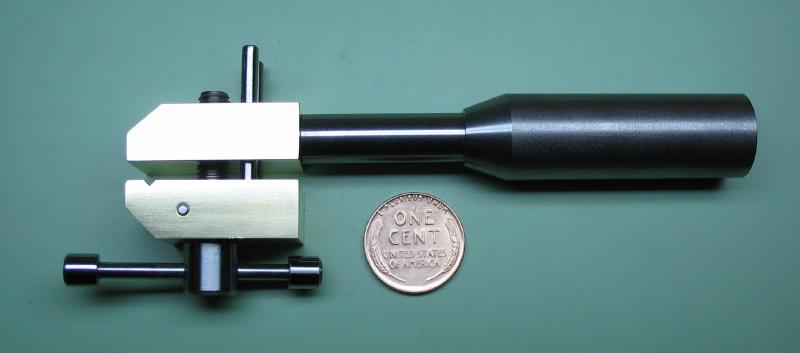
The previous owner of the Palmgren vice made a steel sub-base that weighs the unit down sufficiently enough so that it does not require attachment to the benchtop for most light work. The vice can be positioned in various angles to suit the work at hand.
|
|
|
