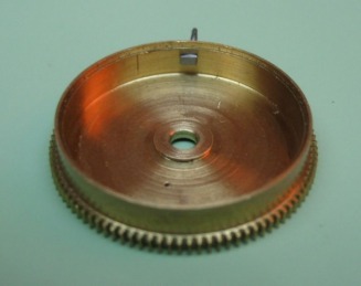
Making the First Part - The Mainspring Barrel
Deciding where to start in making my watch took some thought about what components needed to come before another, before another, etc. Watch components are, of course, interrelated and their execution depend on one another for the determination of final dimensions and fit. As a novice machinist, I wanted to start with something straight forward, and preferably larger in dimension. I decided to begin with the power components, starting with the mainspring barrels. I’ll assume that the reader is familiar with George Daniels “Watchmaking”, and I will follow this text for most of my instruction, among others, including J. Malcolm Wild, John Wilding, Donald DeCarle, William Smith.
My watch will use the twin barrel design, as Daniels points out, this allows for greater power to overcome the inertia of a tourbillon carriage without increasing spring stress, and two weaker springs can be used compared to one more powerful spring. In addition, the power to the center pinion will be at two points, nearly opposing, thereby reducing friction as well. The barrels will use Geneva-style stopwork, and I will discuss this in another post which describes their construction.
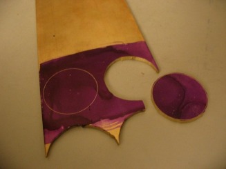
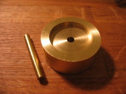
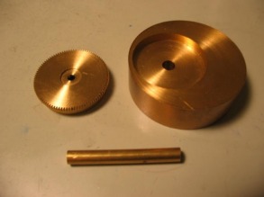
The internal dimensions of the barrel covers need to be started first, the remaining dimensions are finished later after starting the barrel and while it is still in the chuck. The covers start out at about Ø 23mm. I decided to use 1/16” brass plate (~1.58mm) (unspecified, but after some difficulty in turning, it is likely type 260 brass) and cut out discs with a jewelers’ piercing saw.
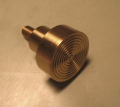
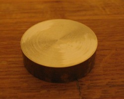
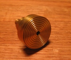
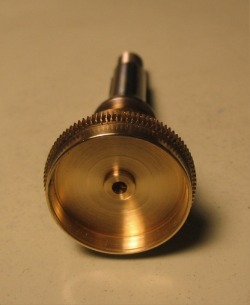
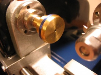
Daniels recommends soft soldering the blanks to a post and holding with a collet. Instead, I decided to machine these by fixing them to a wax chuck. I decided to make a new wax chuck (for practice and in case I ruin it...) from ¾” C-360 brass rod. The wax chucks fit to a threaded collet that has an M5×0.8 internal thread and dies are readily available with this dimension, you can see the finished chuck which had been parted off, fit to the collet, faced, and its surface grooved.
I call it a ‘wax chuck’ which traditionally use shellac and heat to fix components to it, I decided to adapt Bill W. Smith’s super-glue chuck method to the making of the barrel. This obviates the need to melt the shellac and so forth, the blank is simply glued into position by applying glue to the grooves and pressing the blank into position with pressure from the tailstock. The tailstock is locked into this position and the glue left to dry for a few minutes. When finished the component is released by heating with a torch to break the bond and soaking in acetone to remove the residue.
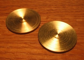
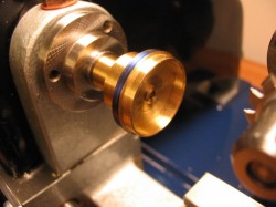
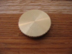
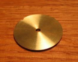
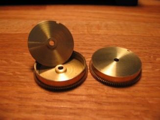
The internal dimensions of the cover are turned and then set aside for now. You can see a pair of embryo covers here.
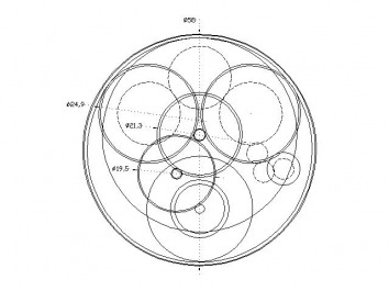
| Movement train layout | |
| File Size: | 303 kb |
| File Type: | |
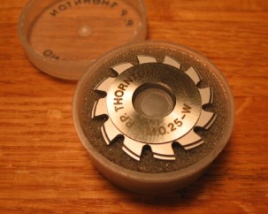
A drawing of the watch’s gear train reveals that there are 24.9 mm of space available for each of the barrels, this can be found in Daniels’ book. The barrels require 96 teeth, the module can therefore be found by FD/(N+addendum allowance)=M, 24.9/(96+2.50)=0.25279... Obviously a profile cutter will not be found readily available with this tooth module. I chose to go with a 0.25M NHS 56704 cutter.
A 1” (25.4mm) piece of C-360 brass rod is a nice starting point. Here is where a Schaublin 102 or a Myford Super 7 would have come in handy, since the rod could be collet chucked and machined as is. However, since I am using an 8mm bore lathe, I need to go about this the same way as the cover, attaching a disc blank to a wax chuck, etc. I needed to deviate from some of the dimensions specified by Daniels for practical reasons, and his book seems to have some discrepancies on these as well. Firstly, he gives an outside diameter (OD) of 23.5mm for the mainspring housing, and even if a FD of 24.9 were possible this would only provide 0.7 of tooth depth which is insufficient for my cutter. In the same chapter describing the barrel construction, the arbor dimensions include a 7.0mm hub diameter. In the mainspring chapter he describes a situation of a 7.3mm arbor hub and a 21.9mm ID housing (using the formula 3 x arbor = barrel), this would agree better with the barrel dimensions shown in the previous chapter, where an ID of 22mm can be deduced. Perhaps I have interpreted this incorrectly, and I understand his book is intended to serve as a guide, not a step-by-step instruction manual. I decided for the time being to use an arbor diameter of 7.1mm giving a barrel ID of 21.3, plus 0.75mm wall thickness to give a OD of 22.8mm. This allows for 0.9125 of tooth depth on the flange, and therefore results in 0.1625mm of calculated cutter clearance. As calculated below the FD of the barrel is actually 24.625mm.
I mention all of this since my first attempt failed. I used the dimensions provided by Daniels and assumed my cutter would be fine. I learned a couple important lessons from this first attempt.
1. Do not assume anything
2. Use all available data/information in making a decision (especially a table full of calculations provided by the cutter maker!)
3. If you consider ignoring rule 1 then you have already violated rule 2.
The various dimensions could then be found using standard formulæ provided by P.P. Thornton.
Pitch Circle (PC) = N x M = 96 x 0.25 = 24mm
Full diameter (FD) (also diameter of blank) = (N + 2.50) x M = 24.625mm
Root diameter = (N – 3.50) x M = 25.125mm
Tooth thickness = 1.41 x M = 0.3525mm
Addendum radius = 2.00 x M = 0.50mm
Addendum = 1.25 x M = 0.3125
Dedendum = 1.75 x M = 0.4375
Full tooth depth (also depth of feed) = 3.0 x M = 0.75mm
Although useful for designing a watch, for the purpose of machining the part at hand, much of this is superfluous, the critical values are blank diameter and tooth depth, as they are needed for the machining steps.
| PP Thornton Horological Cutter Tables | |
| File Size: | 408 kb |
| File Type: | |
Below is a PDF file of the various dimensions for the barrel and cover. I used AutoCAD to draw the components of this watch, it was a great learning experience. I didn't have a lathe at the time and it seemed like a useful project while I was waiting. First, I had to learn to use AutoCAD, not the easiest program to use, and I will admit I am certainly no expert, and not a draftsman, either. However, it forced me to consider many different aspects of the watch and determine various dimensions and details which are omitted or left to the reader by Daniels. I will also say that the drawings were only a guide for my use in the workshop. As one is making things, he discovers (either by accident or deduction) that another way or dimension is better suited.
| Barrel dimensions | |
| File Size: | 248 kb |
| File Type: | |
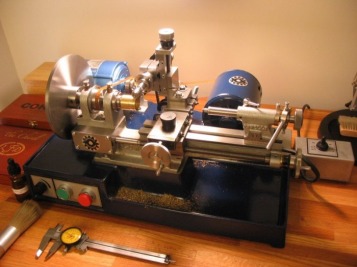
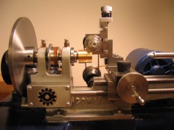
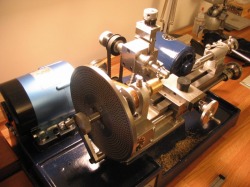
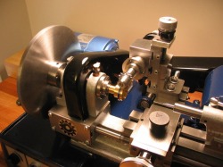
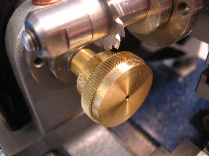
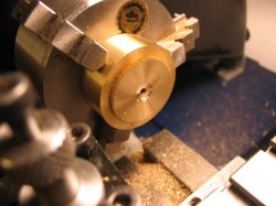
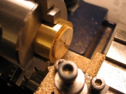
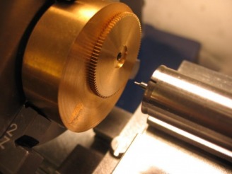
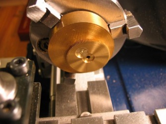
In my first attempt I simply threaded the end of a length of 1” brass rod to fit the wax chuck adapter and thought I would simply part it off when finished. The dimensions were simply not correct for the cutter (insufficient tooth depth), and therefore the teeth were not formed correctly, it was abandoned at that stage. I did, however, take a few shots of the setup which demonstrate the wheel cutting arrangement of the Cowells lathe. If you are curious, I plugged the compound slide hole with a No. 4 rubber stopper to keep the brass chips off the cross slide leadscrew.
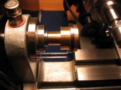
For the second attempt, I started by hacksawing off a disc from the 1” rod, facing one side in the 3-jaw chuck, and then attaching the faced side to a superglue arbor as described previously, however drilled. Shown is the barrel after most of the internal machining has taken place, and I am now ready for my second attempt at milling teeth. Another change specific to the Cowells, I inverted the mill spindle in its housing so that the T-bolts are at the top and the vertical slide will not be extended as much as it is in the previous attempt, this should allow for better rigidity. Also, in my first attempt I ignored all authors’ suggestions of locking the gib-screws of the cross and vertical slides, another source of instability. The mill spindle is run at maximum speed (2400 RPM).
The Cowells horizontal milling attachment was a great selling point of this machine. The spindle accepts B8 collets and in this case, gear cutter arbors. The cutter, as mentioned above, is a P.P. Thornton 0.25 module wheel cutter of the round bottom form (NHS 56704). The barrels have 96 teeth, and the Cowells G2 index plate includes this. You can see in the photo that I’ve coated the outer periphery of the tooth flange with Dykem blue, so as to be able to see the tooth tip landing as I approach full depth with the cutter, which should appear as a thin hairline. I seen this technique used by Bill Smith in his video on wheel cutting.
I had a couple more failed attempts, a couple due to simply not lowering the cutter enough, so that the teeth were not fully formed (they have a flat landing, similar to an involute type gear) and two failures due to something that caused me to be a bit puzzled (and a little worried) until I realized the reason. Specific to the Cowells setup, the index plate adaptor threads onto the headstock spindle and is secured by two grub screws. If these screws are not tightened sufficiently, the index plate will slip a little while moving from position to position, resulting in teeth that vary in width. In retrospect it was such an obvious error, and a lesson to not be so gentle with the hex key. Failures such as these are, of course, discouraging, but were anticipated. Considering it was taking about 8+ hours of work to get to the point of failure, it had been quite a few evenings of work until I had produced a satisfactorily toothed, but not yet finished, barrel.
Here is a barrel where the index plate was not secured properly and therefore caused a variation in tooth widths
Here is one of the barrels where the cutter has not been feed deep enough, you can see the flat top tooth tips
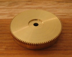
Finally, a successful cutting of teeth, very satisfying experience...
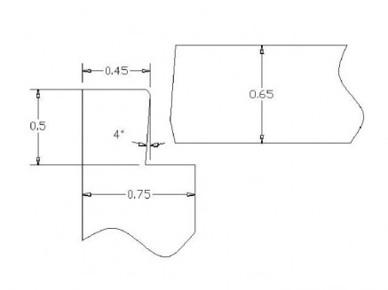
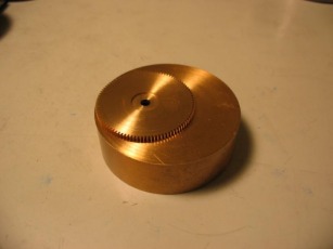
A little out of order, but I had decided to finish the cover prior to milling teeth. With the barrel attached to the super-glue arbor, the cover is snapped into position using the faced collet blank (mentioned in the 'Arrival' post) in the tailstock to provide a uniform flat force. The snap-fit is a result of the cover having a 4 degree taper turned on its edge and the barrel receives a matching taper on its inside edge. This is carefully turned so that the top of the cover will just begin to enter the barrel, at that point the snap fit will be just right, and once faced will leave a tight fit. The cover and barrel are then drilled at the same time. Daniels suggests making a spade drill for this purpose, I used a new 'screw-machine' or 'stub' length drill bit held in the collet holding tailstock. After drilling, the cover is faced flush with the barrel. I had filed a notch prior to snapping the cover in place.
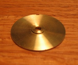
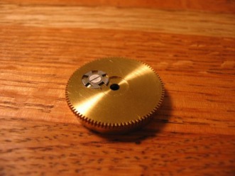
Here is the 'completed' cover, it still needs to be polished and cleaned up, but machining is complete.
With the teeth milled, the barrel is then separated from the chuck, and the bottom faced to the proper thickness, and a recess turned for the finger piece of the stop work. To do this a funnel or step collet would be preferred, however, not owning a set of these, I went about it a bit differently. I made a holder from 1 ¼" Ø brass rod, making a trued disc and then center punching the location of the No.1 chuck jaw and then forming a recess that is a friction tight fit for the barrel. It required some tapping home with a rubber mallet to seat the barrel into place, I assume this ensures a good true seat. To remove the barrel, I had bored a hole in the holder and made a brass punch for tapping the barrel out.
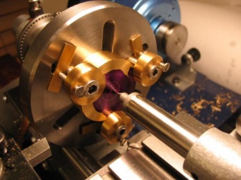
For the star wheel recess, a faceplate would normally be used to position the barrel off center. The Cowells faceplate is different from the standard watchmaker’s type, and is more of the standard toolmaker’s lathe type. I needed to make a set of clamps for holding small parts. The steps for making these clamps has been moved here.
Instead of off-setting each barrel, I decided to make an eccentric jig, similar to the one made previously to face the bottom of the barrel. You can see the clamps in use to set a machined 1-½" brass disc off center on the faceplate for boring the recess. As you may have gathered thus far (I certainly have!) that making watch components almost always involves making various other components first. The benefit is that once they are made, they can usually be used again, so next time the process will be expedited.
The eccentric chuck can then be held in the 3-jaw chuck, a mark was made at jaw no.1 when facing the disc true. Again the barrel is lightly tapped home with a mallet for a snug fit and the recess can be turned using right and left hand boring tools.
The star-wheel recess receives a central boss which serves as the pivot for the wheel. The wheel is secured by a screw, therefore a 0.5mm threaded hole is formed for screwing the star wheel in place later on. To drill the hole for the 0.5mm tap, I decided to make a 0.4mm spade drill for this purpose. I started with a 1/16" O-1 drill rod and turned a shank of 1.5mm, the drill can then be accurately held in a 1.5mm collet in the headstock for making it and in the tailstock for drilling the barrel. The drill took a few attempts to make one satisfactorily. I followed the method described in Lesson 29 of the Chicago School of Watchmaking Handbook. The process is simple enough, however being my first attempt at making a drill and it being 0.40mm, it was a bit of a challenge. The shaft is so thin, turning the back taper and stoning the flats required some patience. Interestingly, the lesson does not mention sharpening the tip of the drill, so I deviated from the lesson in that respect.
| Making a dril from Lesson 29 | |
| File Size: | 349 kb |
| File Type: | |
A more-or-less completed pair of barrels and covers are shown here.
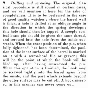
The last step for their completion is the addition of a hook for the mainspring. This is one of the topics which is curiously not detailed in "Watchmaking." He does not mention it at all in the section that covers barrel making, and in the mainspring chapter he briefly discusses some options but does not describe their construction. Photos of his own watches would indicate that he uses some type of hook in the barrel wall or in the spring itself, as found in some Fusee watches. A very good account of the various methods can be found in Glasgow's "Watch and Clockmaking." Since the barrel uses stopwork, I gather that is safe to attach the spring at both ends, since slippage from 'overwinding' will not be necessary. There are also some advantages to a rigid attachment, which I have not yet researched. A hooked mainspring seems to be preferred, however is described as a tricky excercise and has the disadvantage of in the event of requiring a replacement mainspring, the process will need to be repeated. Whereas a hooked barrel wall with a hole end spring, is a bit more simplified, and is described in a number of references, including Jendritzki, Fried, Glasgow and various other works.
I decided to put this on hold for the time being, and will revisit when I locate a mainspring of the proper dimensions, and give the subject some additional consideration.
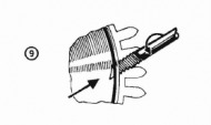
Section from Glasgow's "Watch and Clockmaking" on mainspring barrel hooks:
| Hooking in the Spring from Glasgow | |
| File Size: | 211 kb |
| File Type: | |
Some instructions for inserting a spring hook can be found in Hans Jendritzski's "The Swiss Watch Repairers Manual."
Another method is described in Louis Levin's "Practical Benchwork for Horologists." I chose this method and is as follows.
Making the Hook
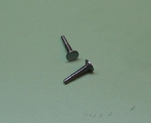
1/8" Drill rod is turned to a small taper and to a diameter to be threaded 1.0mm. The head is machined to taper and full diameter of 2.3mm. This head will form the 'hook' inside the barrel. It is left long so that it can be gripped in a pin vise while screwing it into the barrel wall from the inside-out.
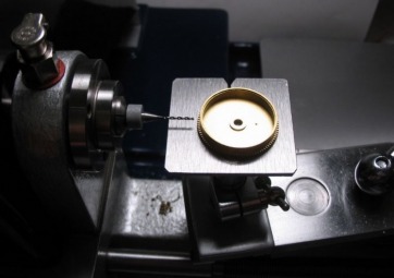
The barrel is drilled on the lathe. Using the saw table which was made to fit the T-rest (see Toolmaking page), the barrel can be positioned to be drilled on mainspring center height. The hole (0.80 mm) is drilled radially, rather than at an angle as for other methods.
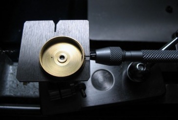
The hook is screwed in from the inside so that it may be fully tightened when in position. The grinding table setup may be used to keep the barrel square while screwing and tightening the hook using the headstock with collet or a pinvise on an arbor in the tailstock, etc.
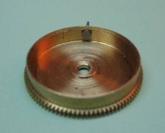
When the hook is fully tightened, the head is marked to know its orientation when unscrewed. The head of the hook can then be filed away to leave just a 1.0 mm width hook to fit into the punched mainspring hole (see Mainspring page).
The hook can then be screwed back into position and the excess portion outside the of the barrel can be sawn and filed off to be smooth with the barrel wall.
