Wheel Crossing Jig
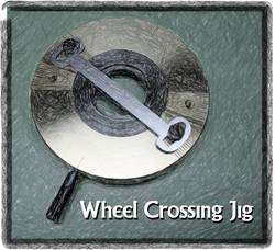
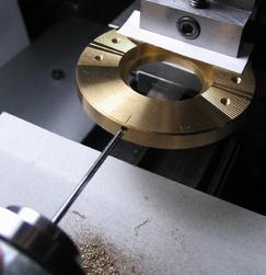
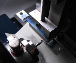
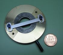
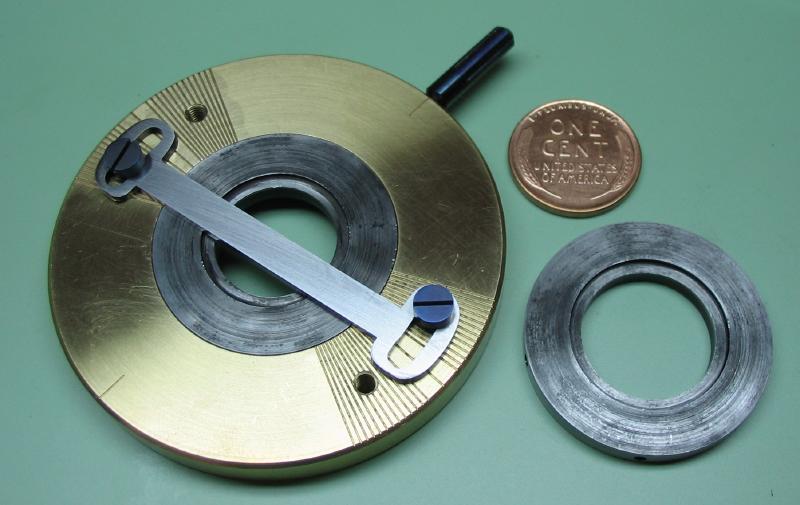
I have described my attempts at wheel-making, and filing the crossings by hand. The final spoke shapes were less than perfect; filing by hand and eye takes some practice. To assist in this work, I decided to make a crossing jig. In J. Malcolm Wild's book, "Wheel and Pinion Cutting in Horology," he demonstrates the use of a home made jig for filing watch wheel crossings (spokes, rim and hub). He provides a photo of the components and a line diagram of it's function. It consists of a hardened steel workholder which holds the wheel and acts as the guide for filing the rim. It is drilled for indexing the work in the tool. A brass frame holds the steel workholder and has an adjustable hardened steel straightedge to guide the filing of the spokes.
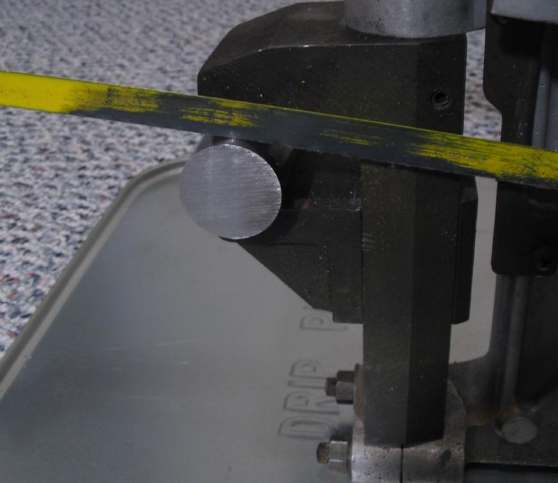
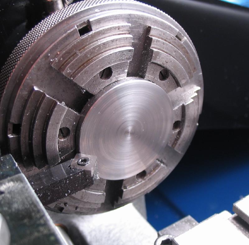
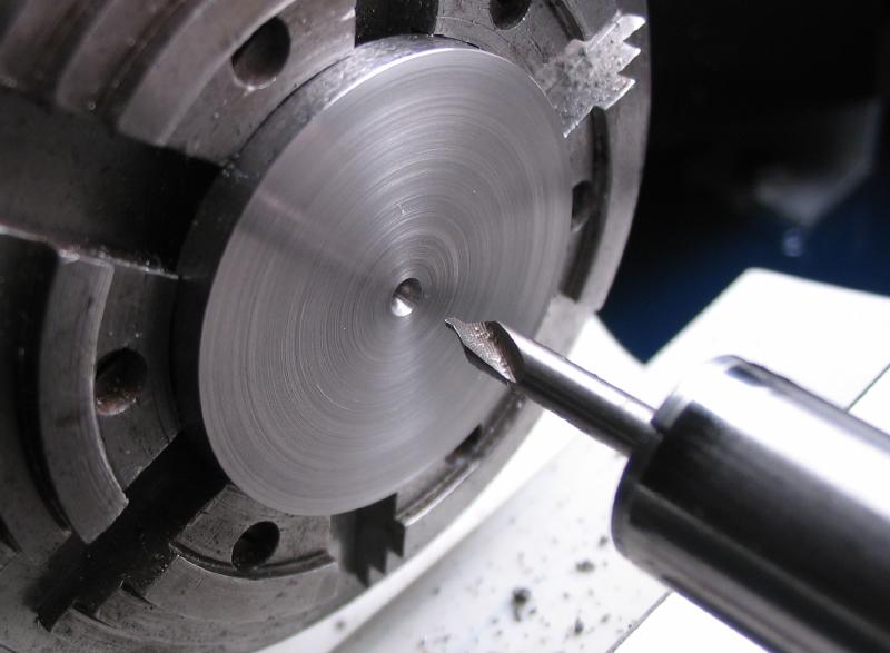
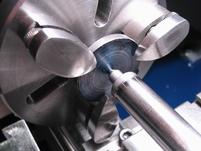
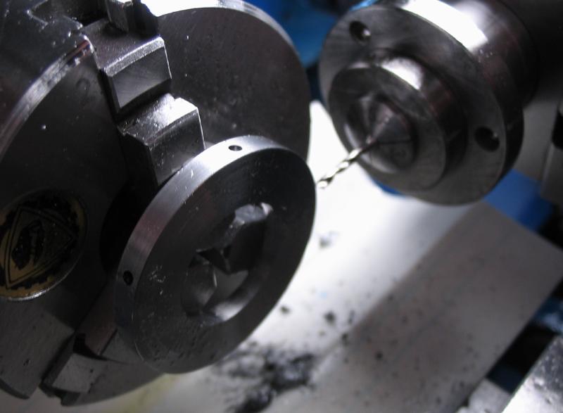
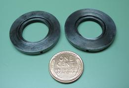
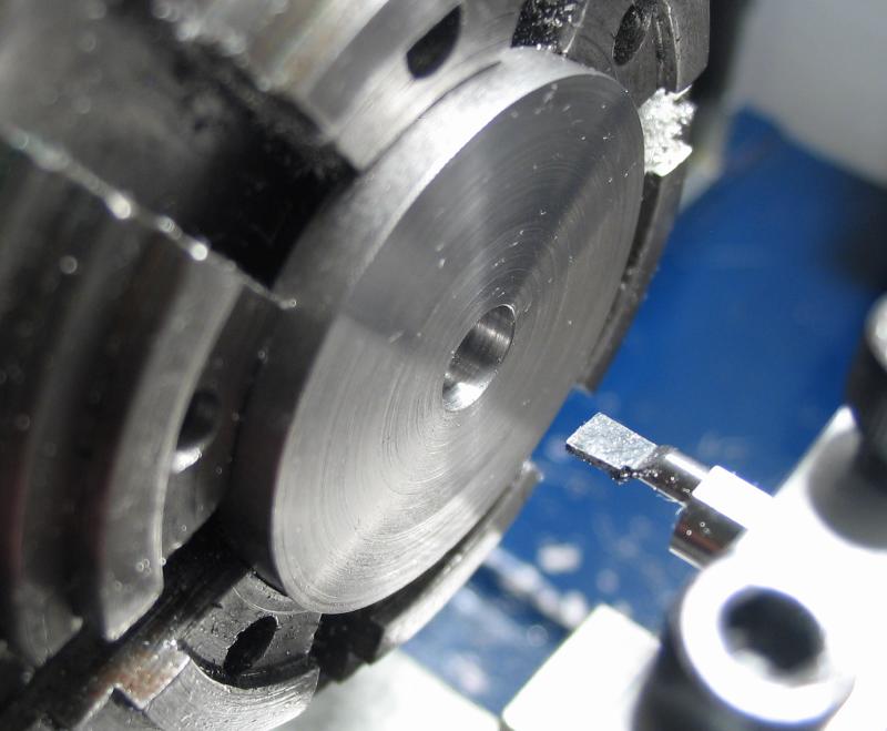
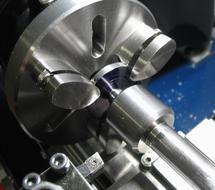
I started with a workholder. A different one will need to be made for each size wheel, however, they are reusable for making the same wheel again. I started with 1-9/32" diameter oil hardening (O-1) drill rod. Hacksawing this diameter of tool steel would be quite the chore, fortunately the Hand-I-Hack was on hand to do the hard work. A disc of about 5mm thickness was sawed off. It was then faced on both sides using the six-jaw bezel chuck to hold it on the lathe. It was faced down to 3.5mm in thickness, and then center drilled for reference.
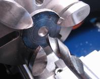
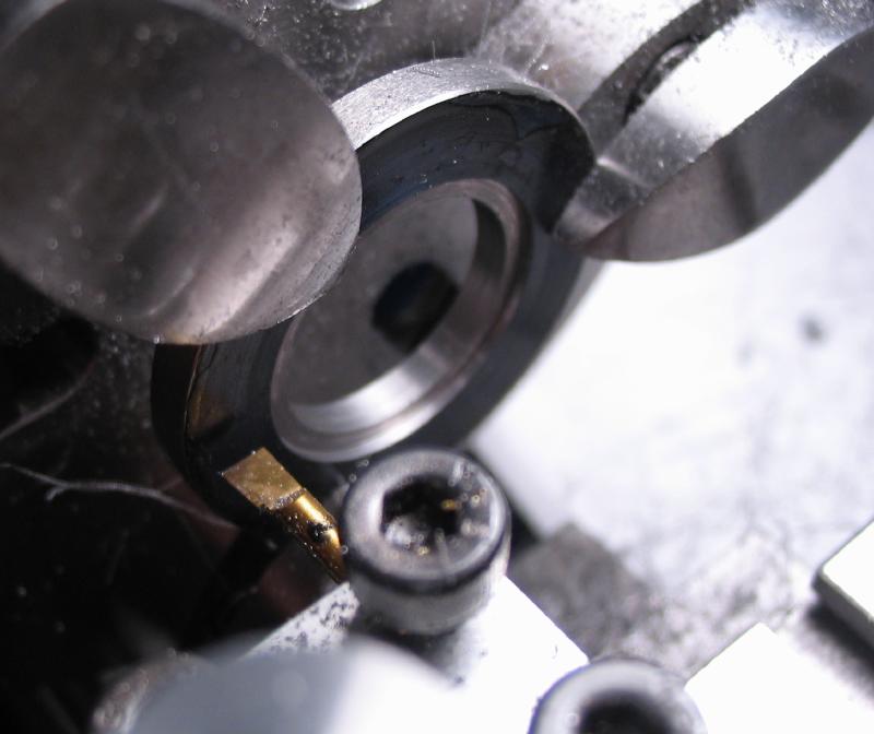
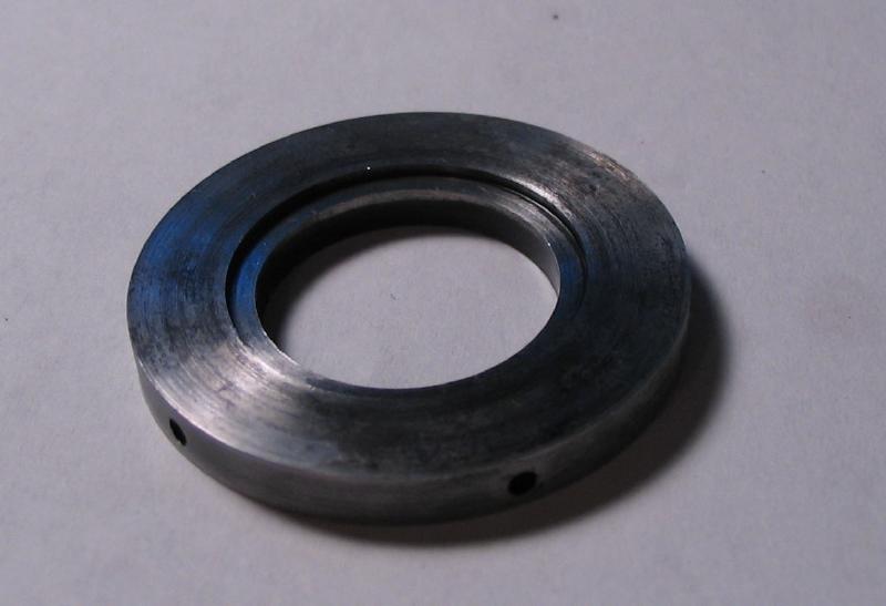
The tailstock center is used with the reference to set the disc up on the faceplate. It was drilled open to allow for boring the disc to an inside diameter of 17.5mm (center wheel rim diameter). It was then counterbored to the full wheel diameter plus a little clearance (~20.7) and to a depth equal to the wheel thickness plus clearance (~0.75mm).
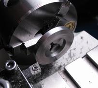
The work was transferred to the three-jaw chuck and turned to final diameter (32mm). With the headstock locked, five indexing positions were drilled (1/16") into the periphery.
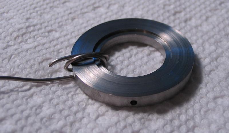
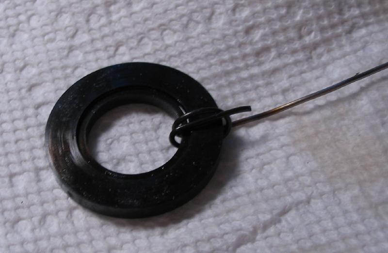
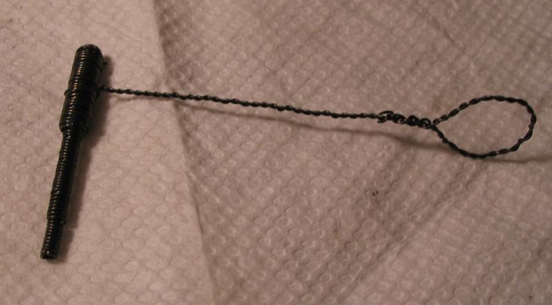
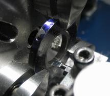
The disc was then suspended on a length of wire and hardened by heating with a propane torch and plunging into oil. It was cleaned up with a brass-wire brush and left fully hard for use.
Another wheel holder was made for the third wheel dimensions.
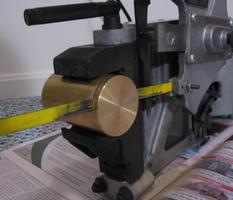
The frame is made from brass rod. To start, a piece of 2-3/8" (~60.3 mm) diameter 360-type brass rod was mounted in the saw to cut off a section about 7.5mm thick.
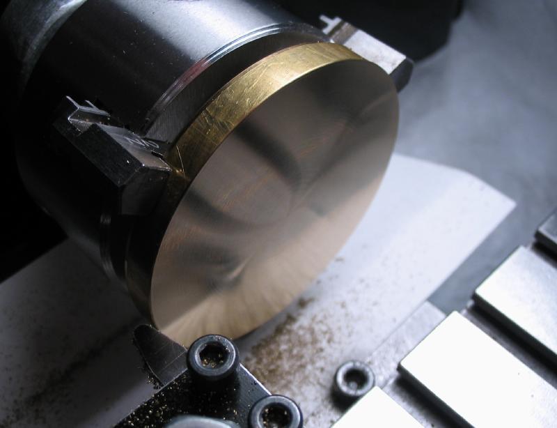
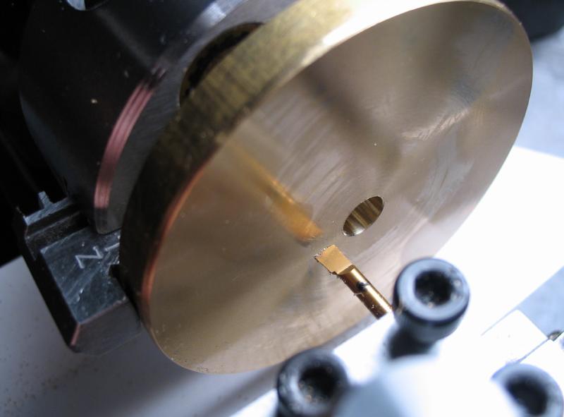
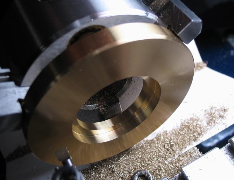
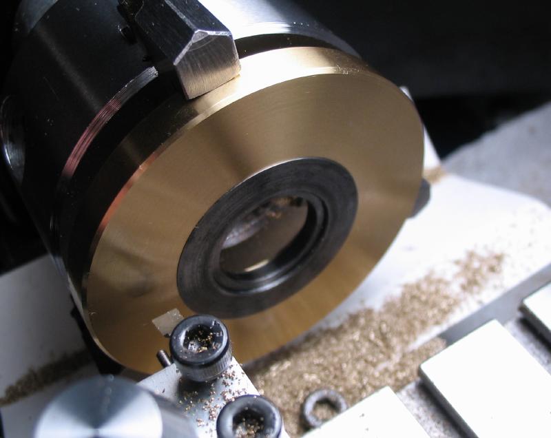
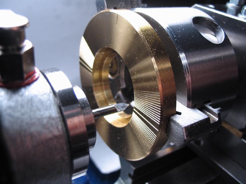
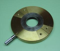
The brass disc is held in the 3-jaw chuck with jaws reversed to face both sides and true the disc to a uniform thickness. An exact thickness did not seem critical, and ultimately was about 7mm. The disc was drilled and bored to 1/4" to fit an arbor, in this case a Levin grinding wheel arbor. This allows the outside diameter to be turned true and chamfer the corners 45 degrees as well. The disc was then moved back to the 3-jaw chuck to continue boring open to about 26mm and finally counterbored 32mm to accept the wheel holder made above.
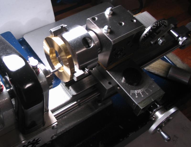
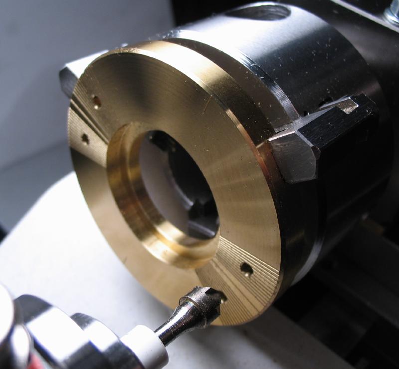
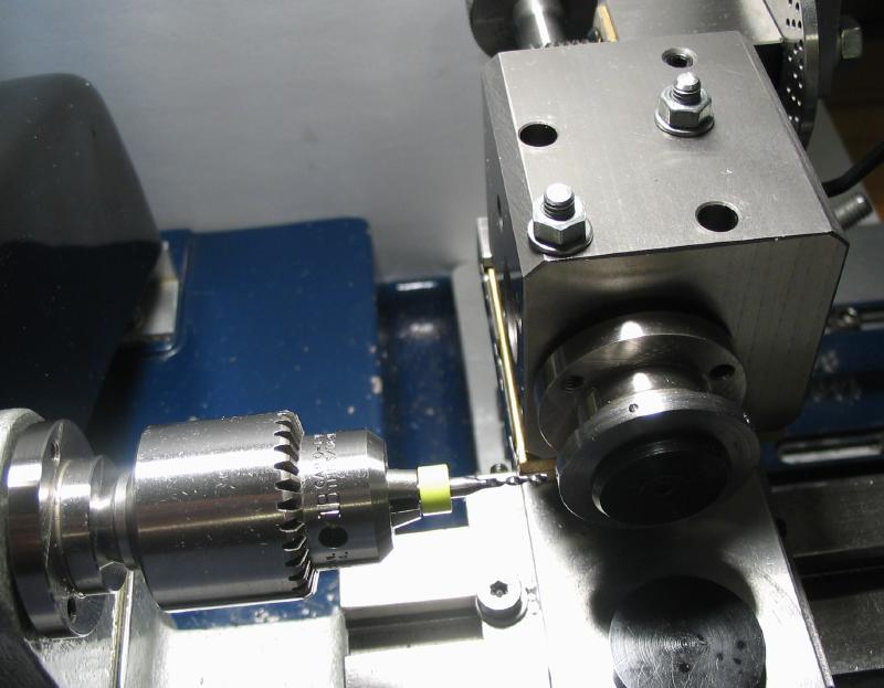
The work is kept in the chuck and transferred to the dividing head which is mounted on the cross slide with the riser to bring onto lathe center. Angular graduations were engraved onto the surface of the frame using a 1/8" engraving bit to a depth of about 0.15mm. I made graduations for 20º starting at 5º from the center line in each quadrant. There are thirteen graduations which is 1-2/3º. That is kind of an odd choice, but the engraved lines would be too tightly spaced at 1º, and 1-2/3º is still divisible into 5º, so marks are present for 5, 10, 15, 20, and 25º with two graduations in between each. The dividing head is setup for indexing 216, which is 5/27th of a rotation of the crank for each increment. A center line was engraved first, and reference marks at 90º were made, followed by the 52 angular markings.
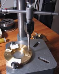
Positions for the screws to attach the straight edge were drilled (2.5mm) at 15 degrees from the center line in each quadrant and then countersunk. With the holes drilled, the work can be removed from the chuck and the holes tapped M3x0.5.
The brass frame is then mounted in the machine vice and setup to drill the position for the indexing pin. It was drilled 1.9mm and reamed 2.0mm.
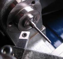
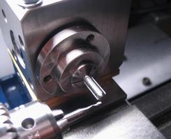
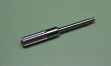
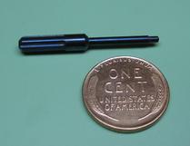
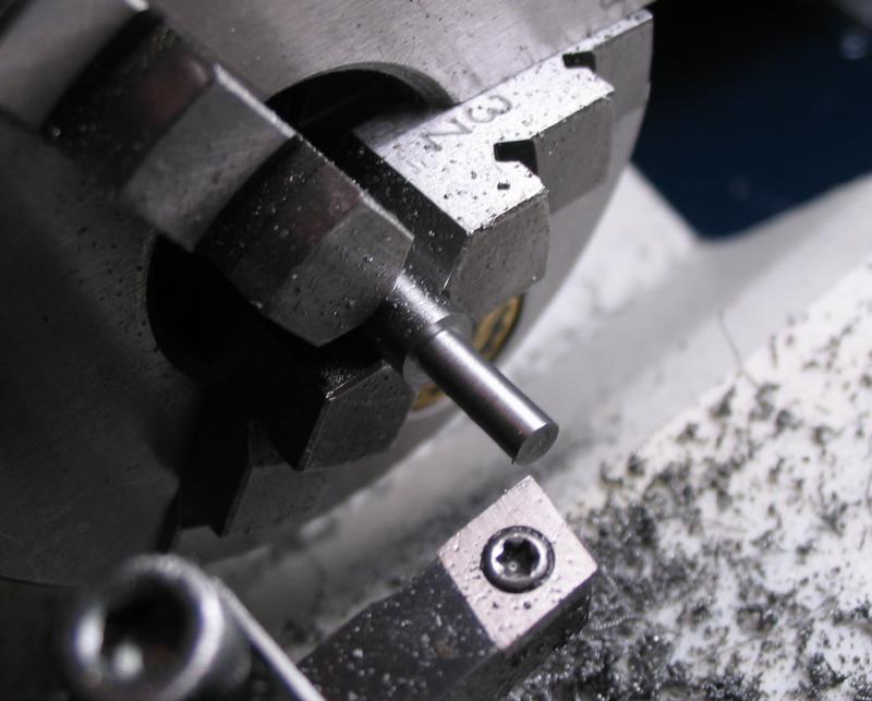
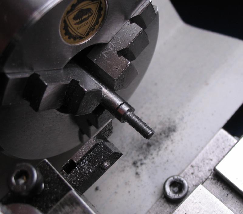
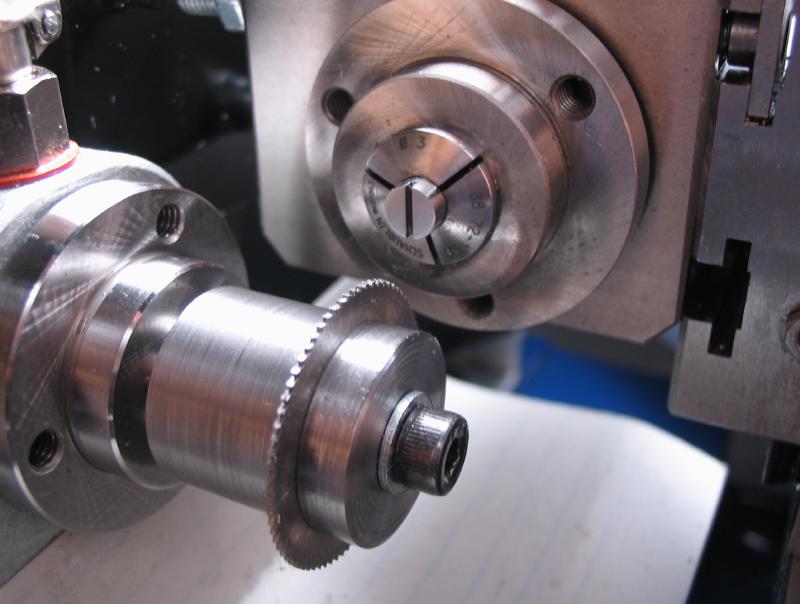
The pin was turned from 4mm O-1 drill rod. The 1/16" diameter tip and 2mm shaft were turned first. The handle portion was chamfered 45 degrees. The 60 degree center on the tip was filed off and then rounded off with a jewelers cup bur. The pin was then transferred to the dividing head held in its collet to mill five slots in the handle for easy gripping during use. A 1/16" ball end mill was used. It was then hardened in oil and tempered to a purple-blue on a bed of brass swarf.
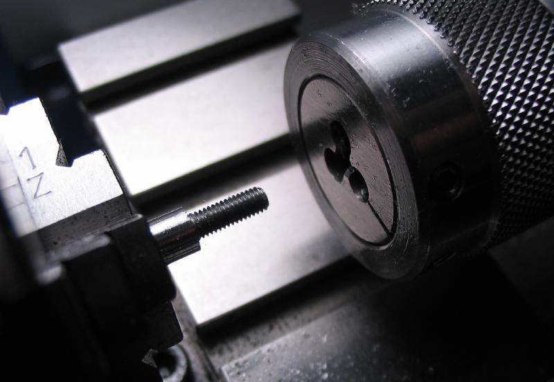
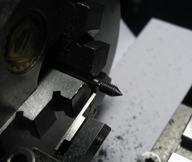
Screws for the straight edge were turned from 5mm O-1 drill rod. A length of 8.4mm was turned to 3mm and then threaded M3x0.5 using a die. They were parted off to have a 2mm wide head, and then slotted with a 0.023" saw. Finally, they were polished, hardened in oil, and tempered.
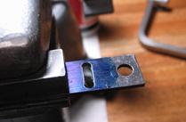
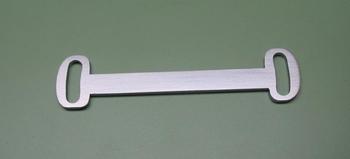
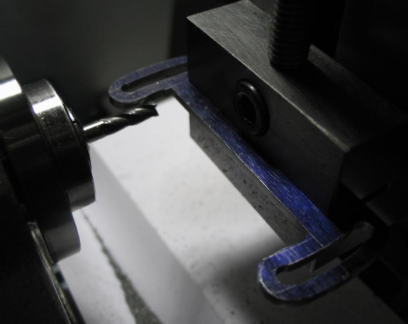
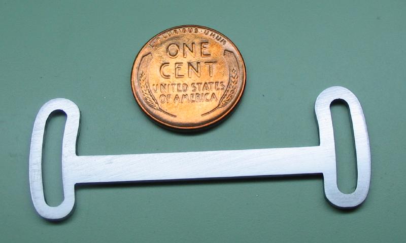
The straight edge was made from a piece of 1/2" x 1/16" oil-hardening gauge plate. Not having any in the stock bin, I reused a piece that had been previously made into a clamp. It has two 5mm holes that will ultimately be sawed off. For use on the jig, four 3mm holes were drilled for passing the screws made above. The holes were connected using a jeweler saw and filed to shape. The straight edges were coarsely sawed out and then finished on the lathe by holding in the vice and using an small endmill.
The outer ends of the straight edge were sawn and filed to shape. It was polished on emery paper and the straight edges stoned with an Arkansas slip stone. It was then hardened in oil and the polishing repeated. It was left dead hard for use.
The primary components of the jig can now be assembled.
While making a work holder for another wheel, a few steps in the process were changed. The holder was started as before with a sawed off disc of 1 9/32" O-1 drill rod that is faced on both sides, but then drilled and bored to provide a 1/4" hole to mount the disc on an arbor for turning the outside diameter and drilling the indexing holes. The disc was then centered on the faceplate for boring the hole and step for holding the wheel.
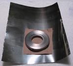
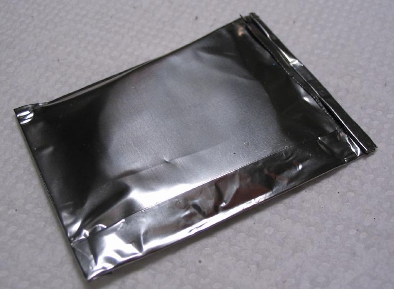
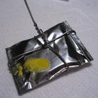
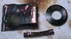
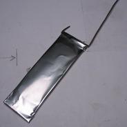
I also experimented with a new method of hardening the steel disc. It was enclosed in a packet formed from a section of stainless steel foil. The foil is marketed for this purpose and is listed as 321 grade stainless steel and 0.002" thickness. A piece of brown paper was included in the packet and the edges of the foil folded over twice on each edge. The packet was wrapped loosely with wire to form a holder and a dab of Templiaq 1450 applied on the surface. This was my first use of Tempilaq and between the dim lighting of my makeshift heat treating area outside and the brightness of the torch, it was difficult to observe while heating. However, upon examining the aftermath it appears to have melted, which indicates that at least 1450 °F was reached at some point. The foil packet was intended to provide a closed, low-oxygen environment, however, it appears there was a breach as the packet filled with oil while quenching and the holder was blackened as usual. Despite this not going exactly as anticipated, the holder seems to have been hardened in the process.
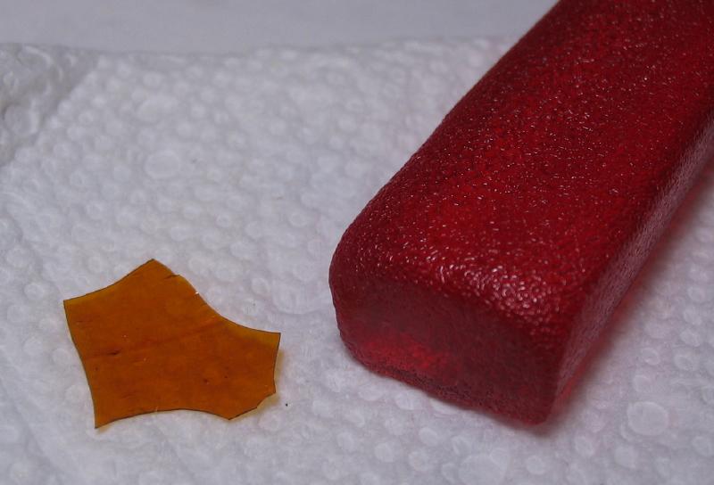
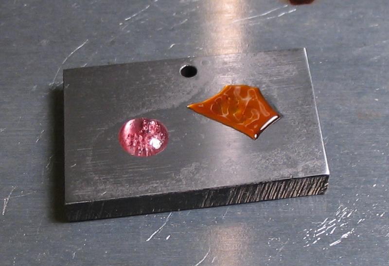
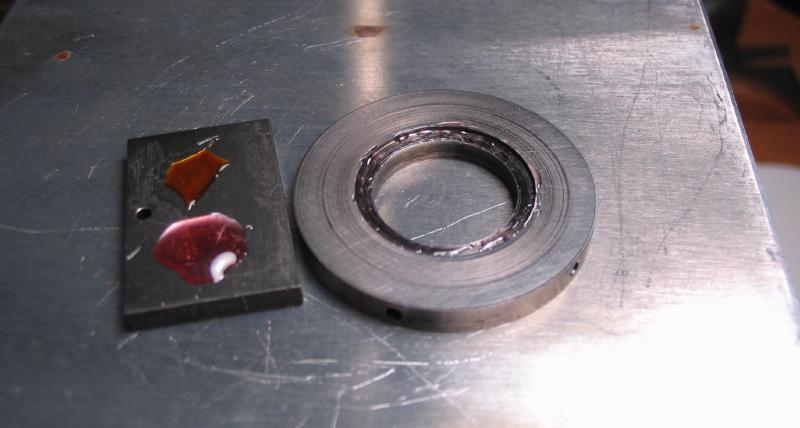
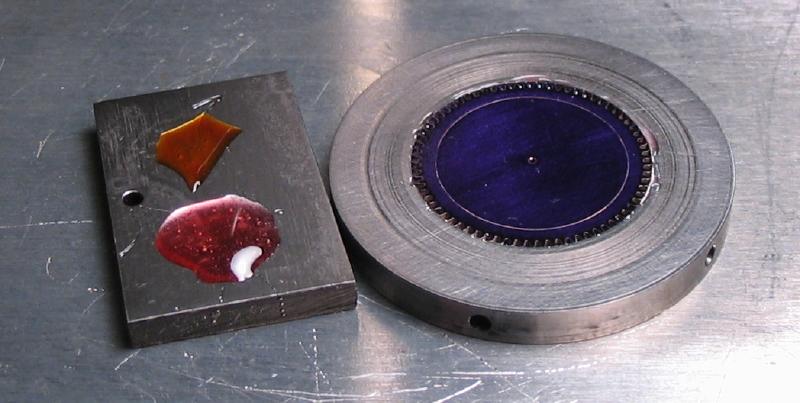
Shellac can be used to attach the wheel to the steel holder. I obtained two different shellac products, one is amber-color flakes and other is a red-color bar. The bar shellac cracks and crumbles when trying to cut it, so the products are actually somewhat similar in that regard. A piece of 1/4" aluminum plate was setup as a hotplate with an alcohol lamp underneath as the heat source. A small sample of each shellac was placed on a piece of scrap steel and observed while warming up. The piece of scrap steel was hardened and rubbed on emery paper beforehand in order to observe whether the melting temperature of the shellac caused in any color changes (i.e. tempering) of the steel, which it did not appear to do.
I preferred the consistency of the molten bar type of shellac. It seemed to melt at a slightly lower temperature and was a little easier to work with for this application.
The work holder was placed on the aluminum hotplate to bring up to the same temperature, and a piece of peg wood sharpened to a chisel point was used to dab the molten shellac around the counterbore of the holder. The wheel was then pressed into place and some of the excess shellac wiped off while still warm.
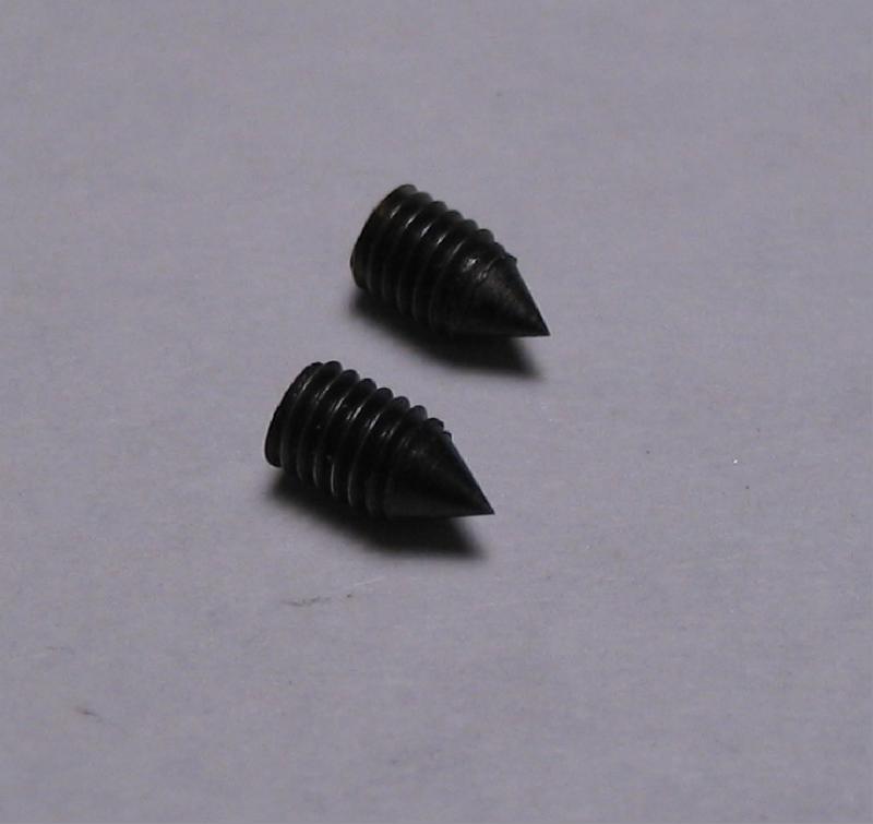
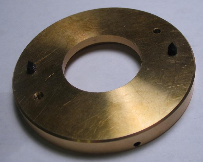
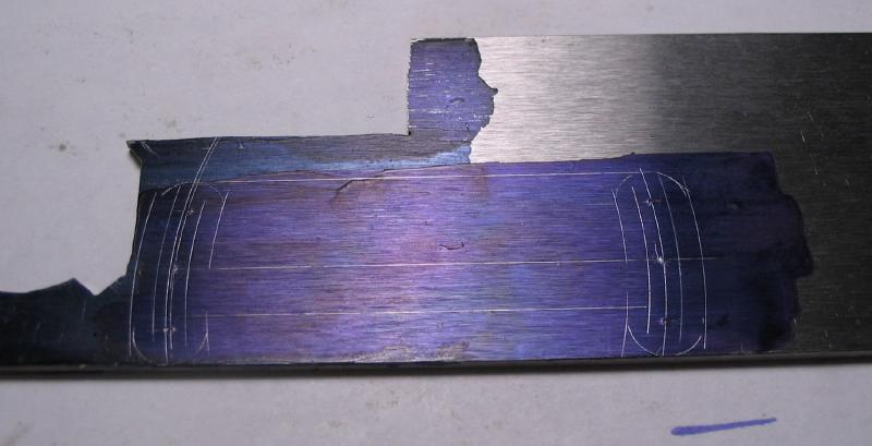
Another straight edge was made that has a wider range of adjustment. It was made in about the same manner as described above, but starting with a 20mm width of 1/16" oil hardening plate. A pair of transfer screws were made from 1/8" drill rod that was turned, threaded M3, the end turned to a 60 degree point, and parted off. They were hardened and screwed into the brass frame of the jig to scribe arcs for the screw slots. The straight edge was roughly sawed out and milled to flatten the important edges. The slots formed by drilling, sawing, and filing. Surfaces were smoothed on emery paper and hardened for use.
