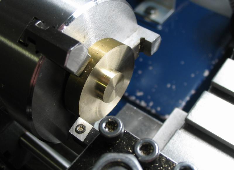
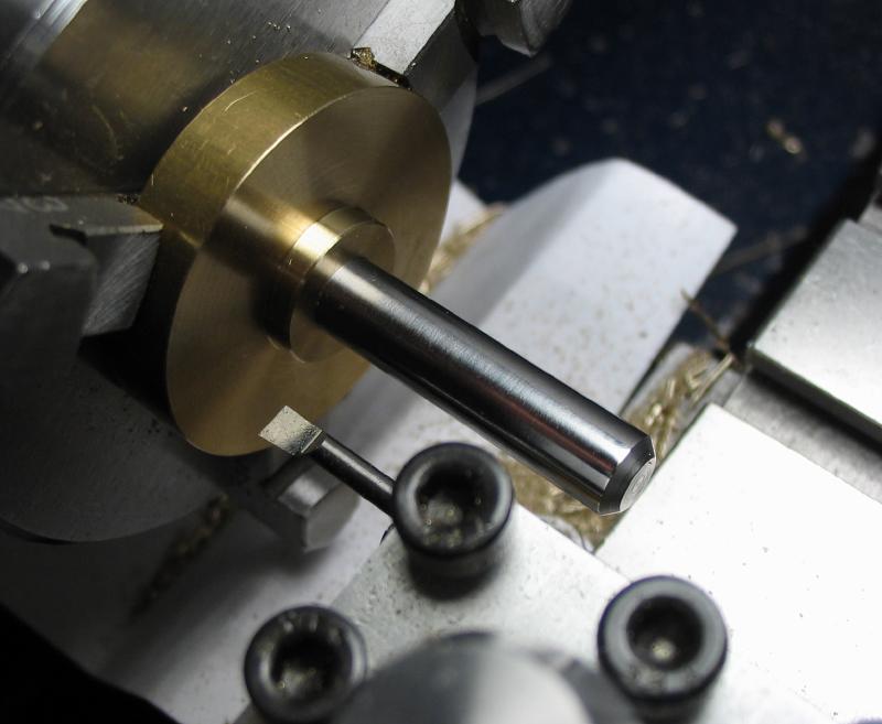
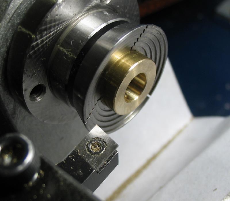
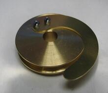
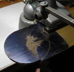
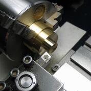
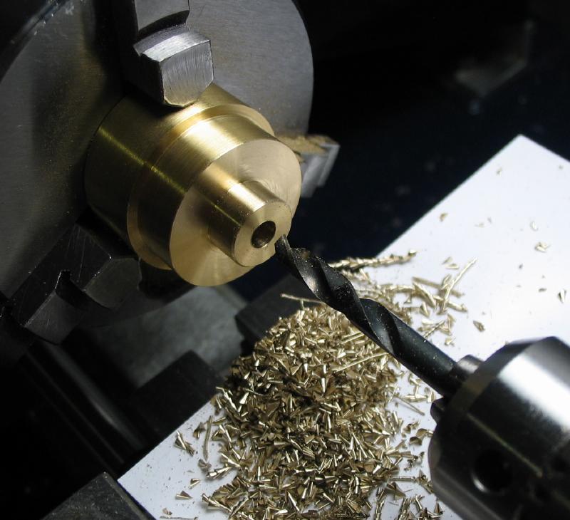
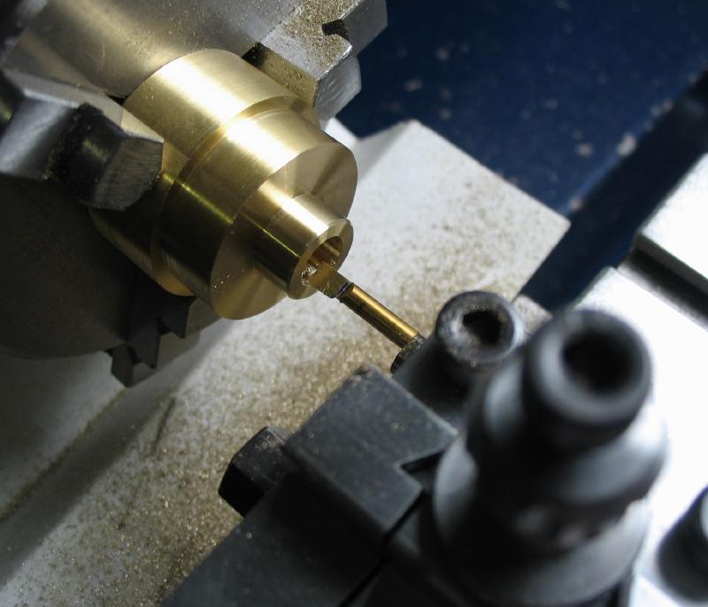
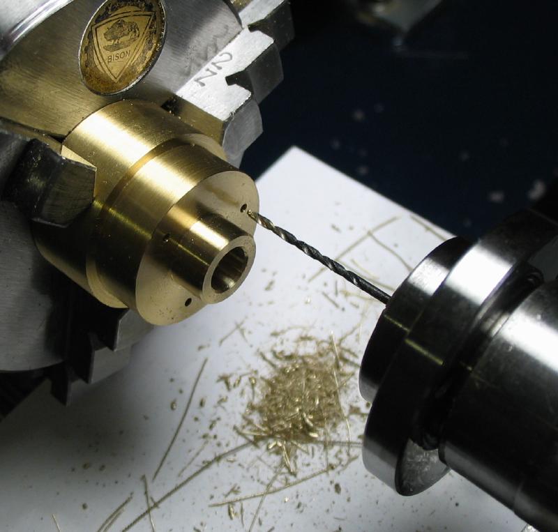
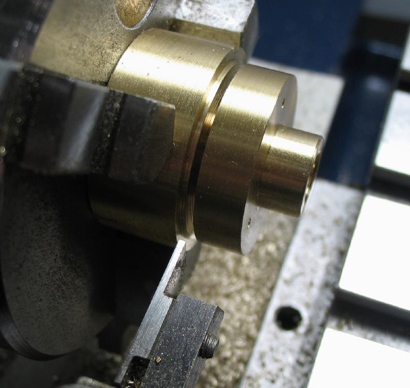
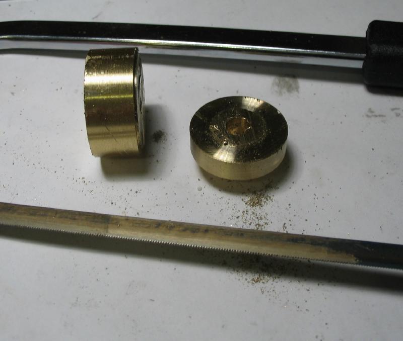
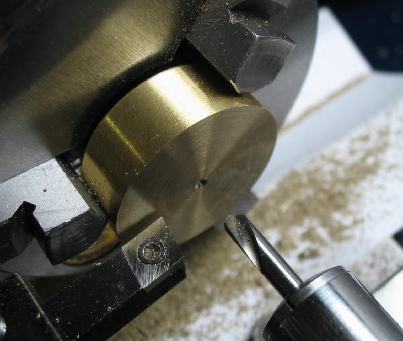
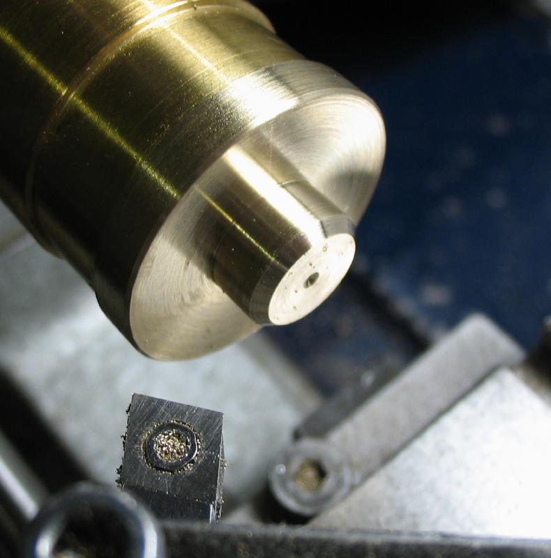
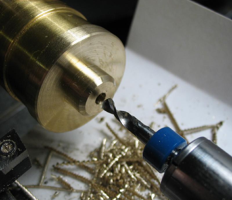
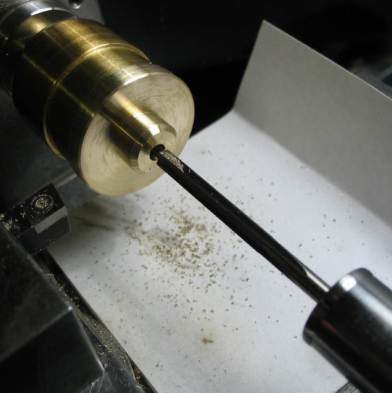
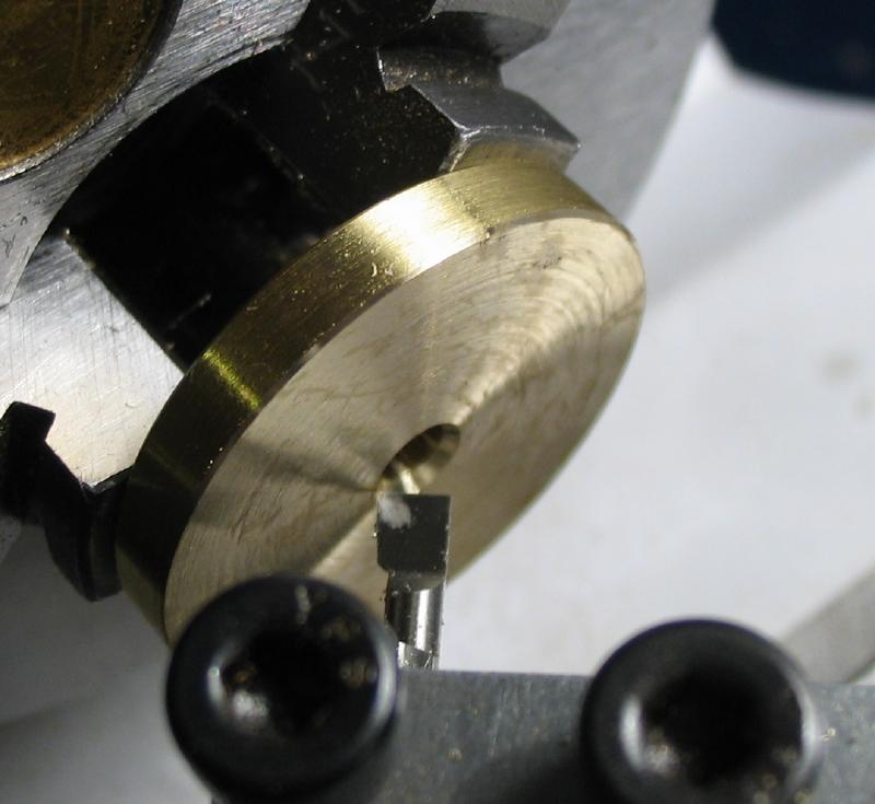
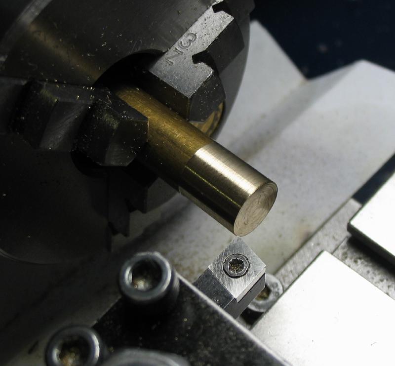
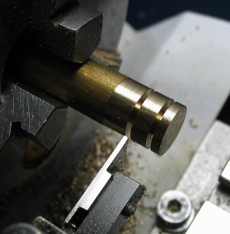
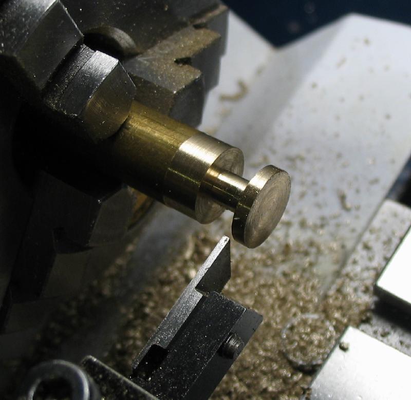
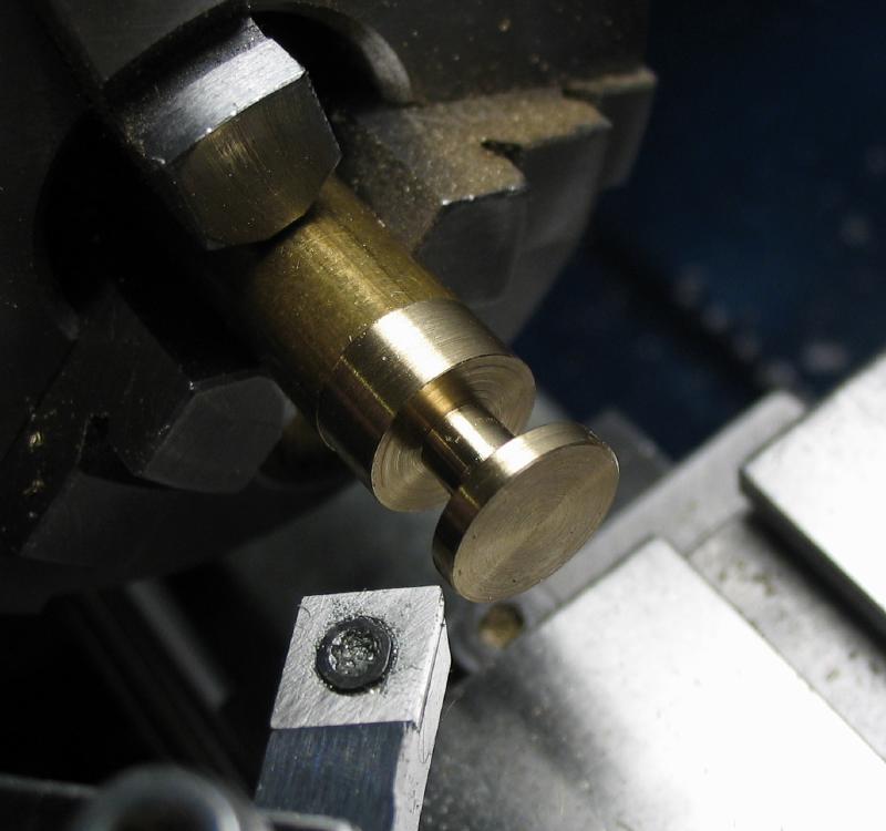
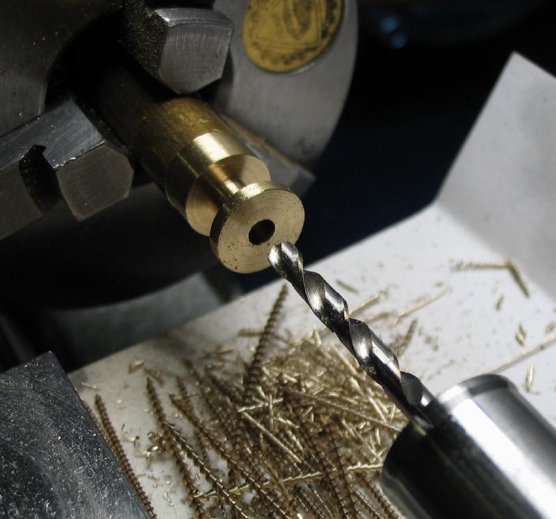
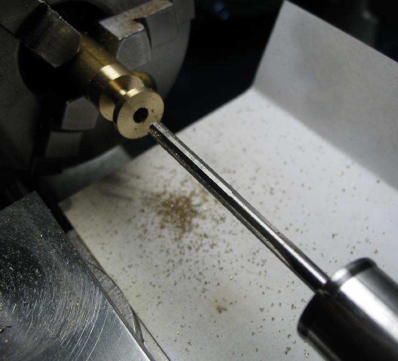
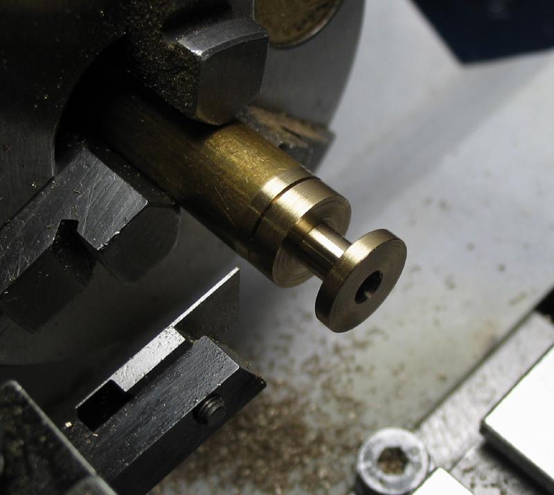
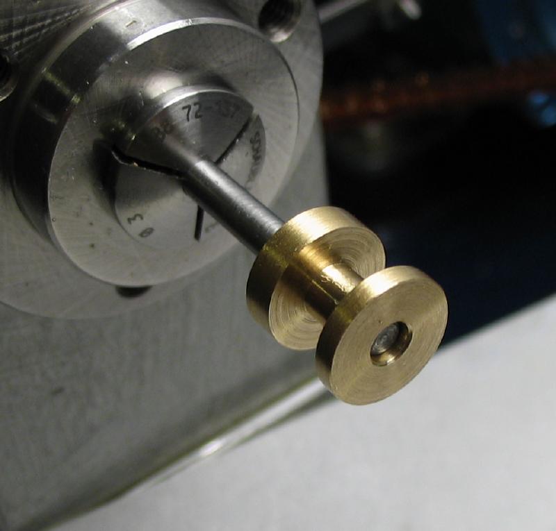
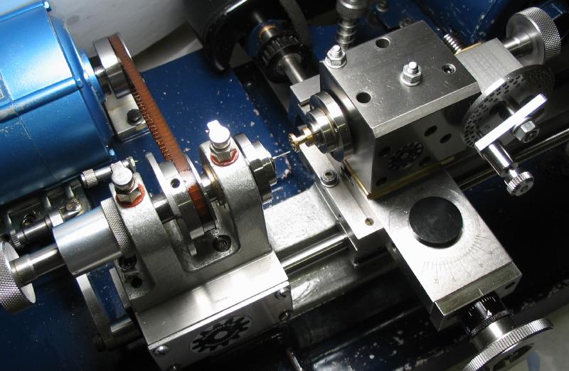
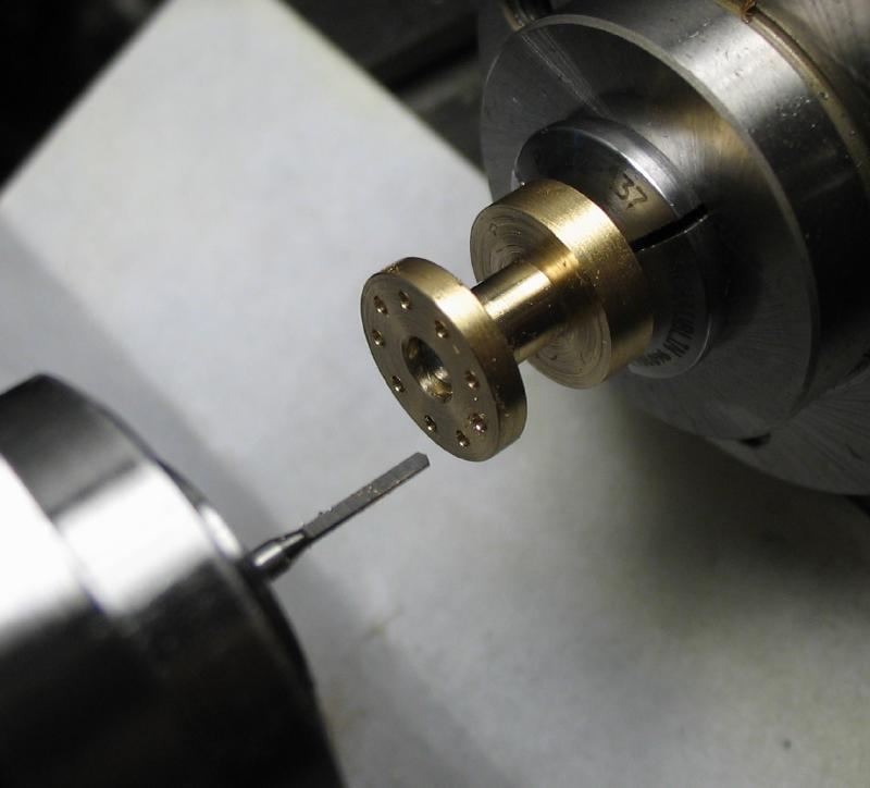
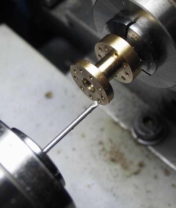
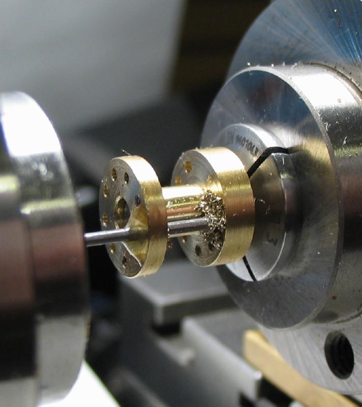
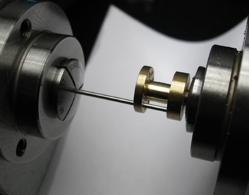
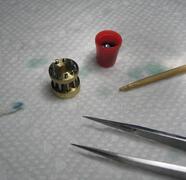
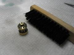
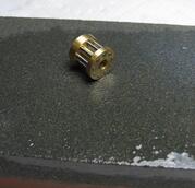
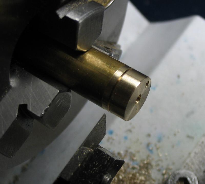
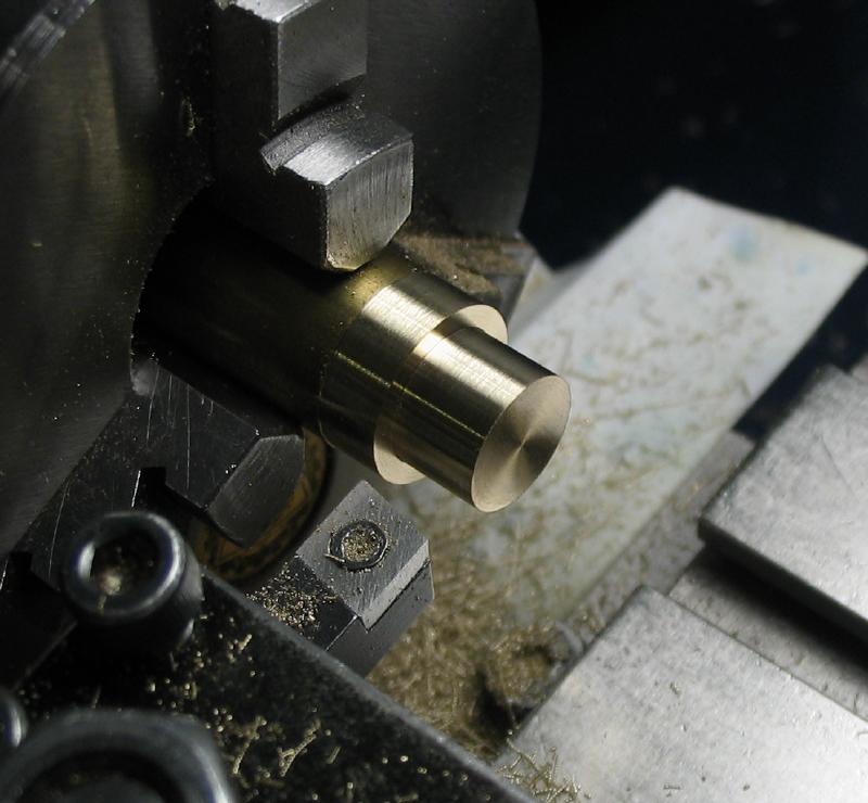
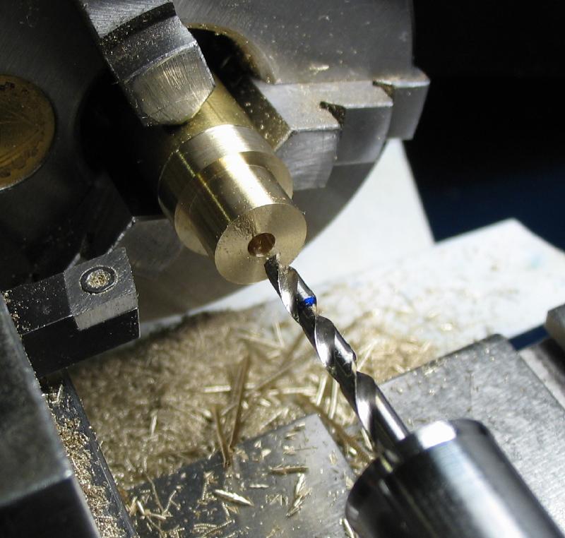
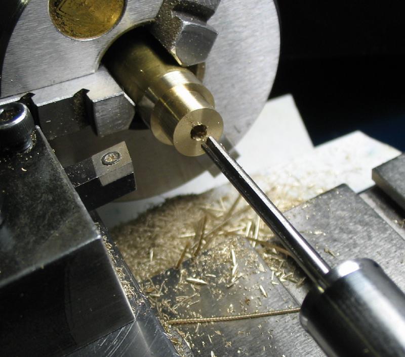
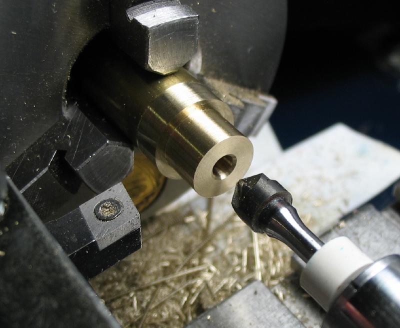
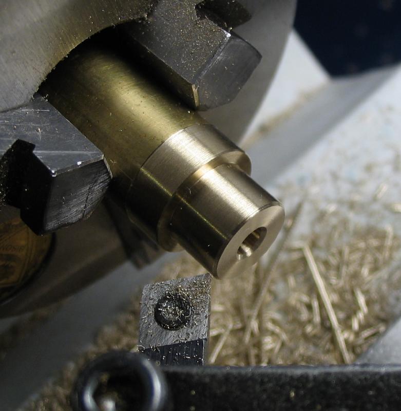
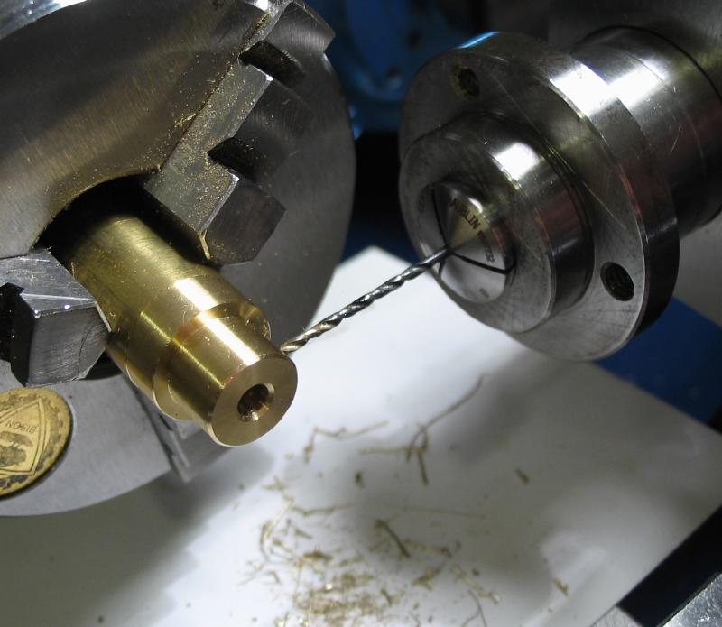
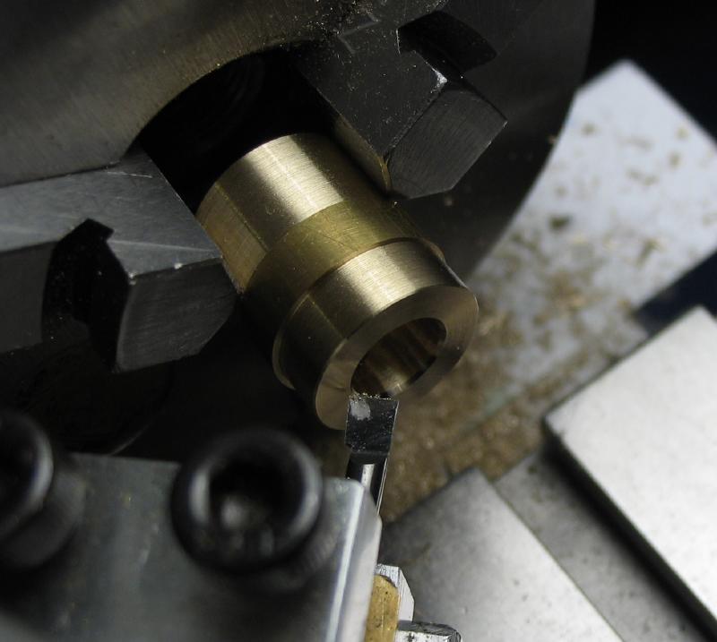
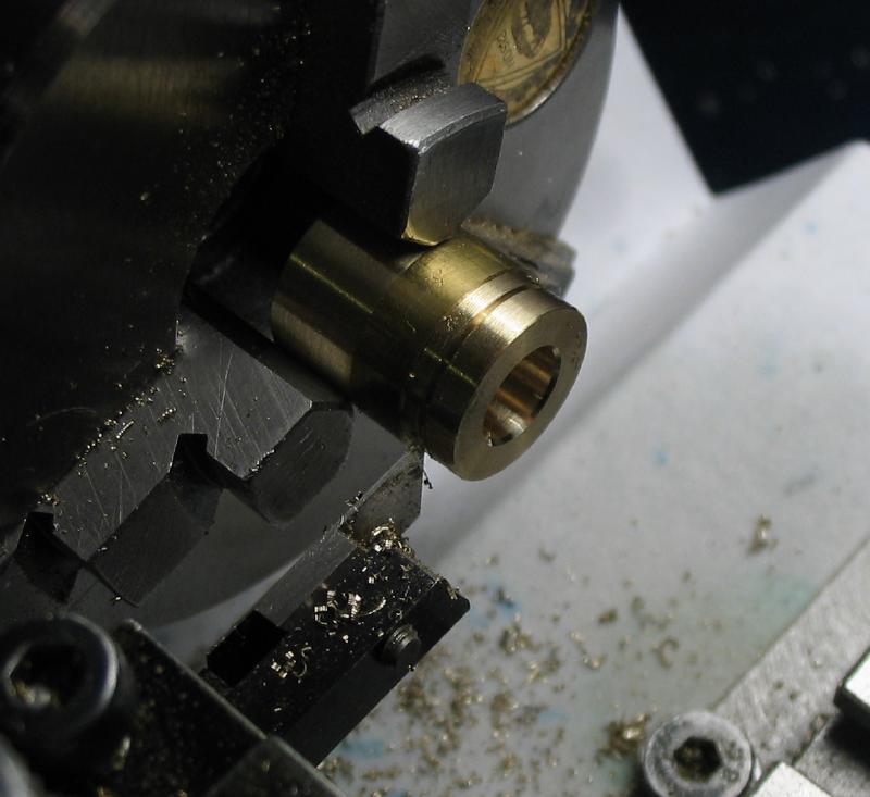
The drive pulley was started from a disc sawed from 1.25" diameter brass rod. The sawed faced were turned and a boss formed. The center hole was drilled and bored for a smooth fit to a length of 1/4" drill rod. The rod will be the arbor that the pulley will ultimately run on.
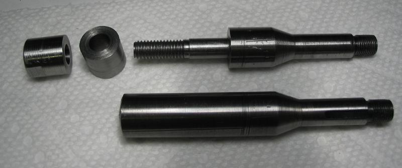
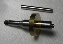
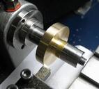
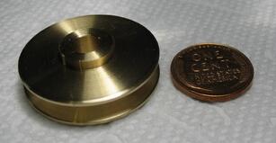
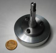
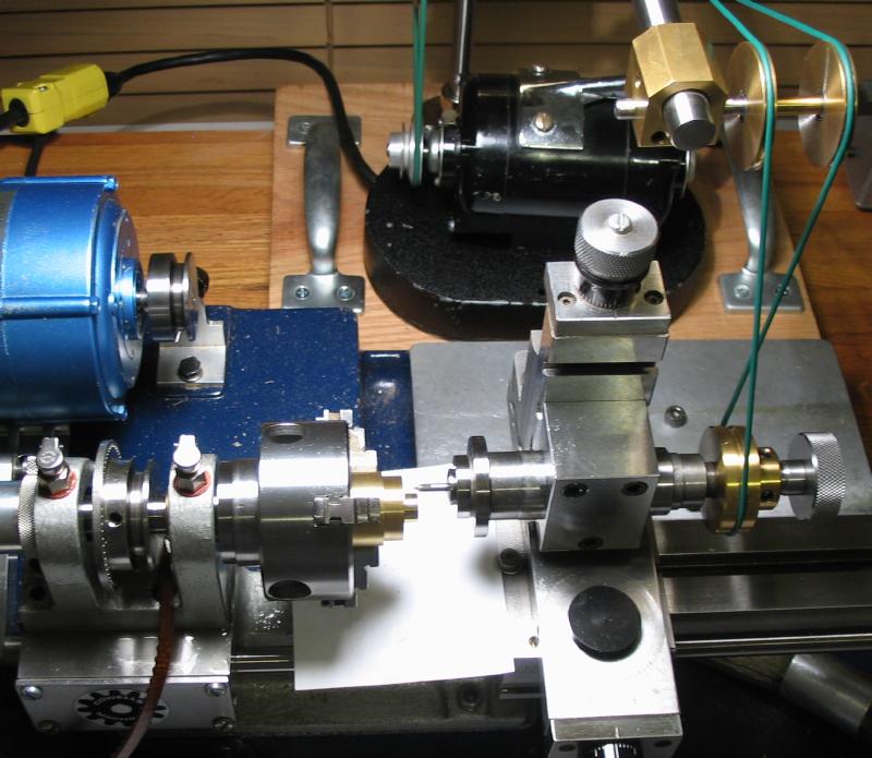
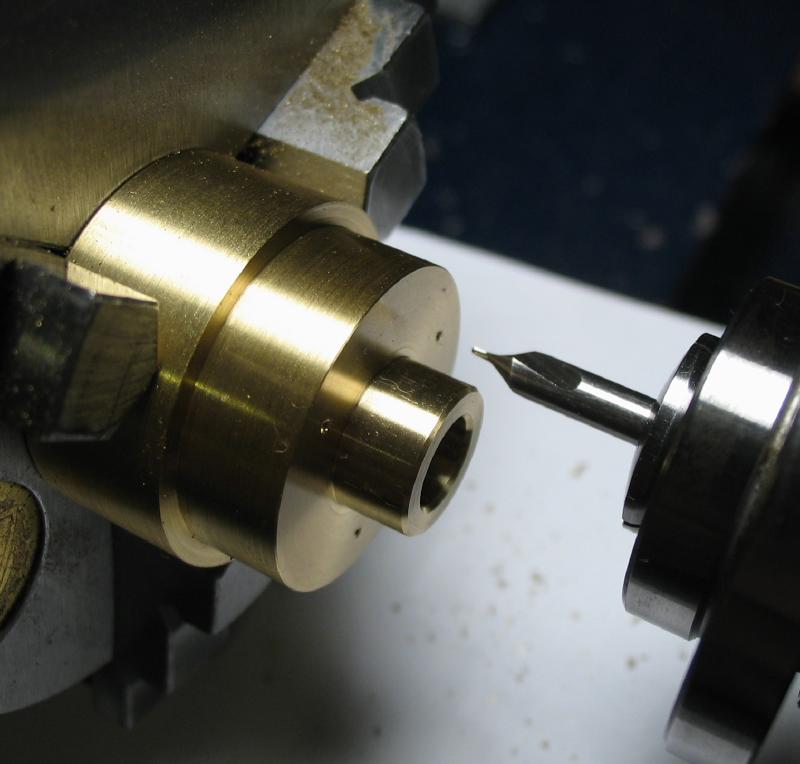
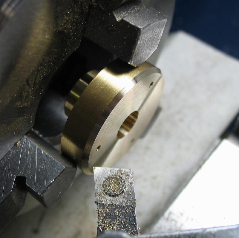
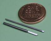
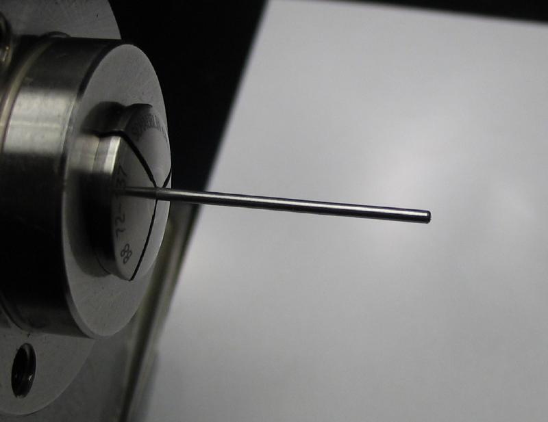
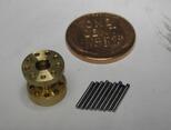
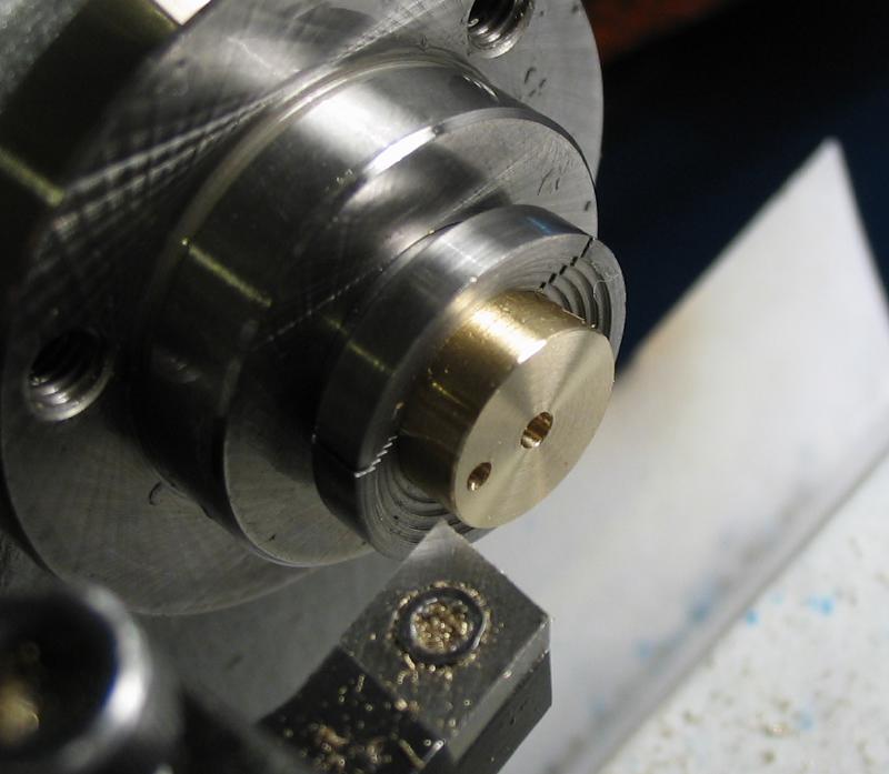
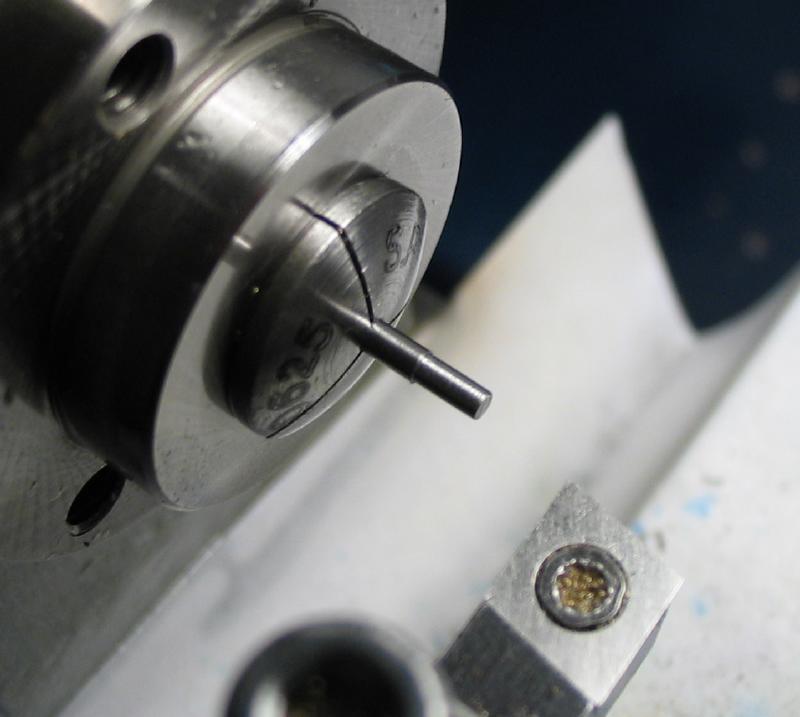
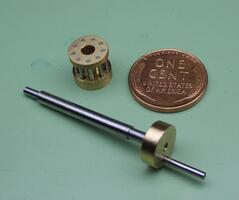
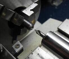
To turn the remaining dimensions, the work was mounted on a collet type of arbor. This one was made from a collet blank, an example of which is shown in the photo as well. This arbor was one of my earliest projects and has had many uses, and a short washer was made from brass rod to give a better fit.
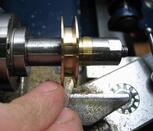
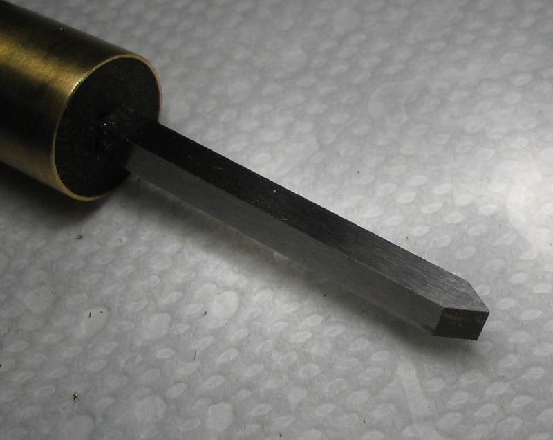
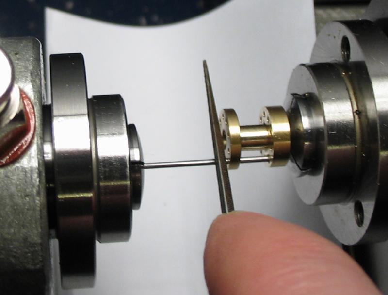
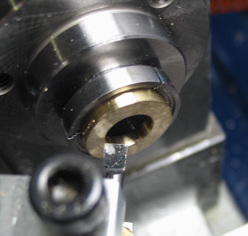
The pulley waist was formed with a parting tool followed by hand turning. A graver had been made from 1/8" high speed steel tool bit that was ground with a 60 degree point. The angled walls of the interior are specified as 70 degree taper, and this had to be estimated by eye since setting the top slide to this angle was not possible.
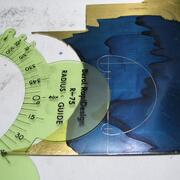
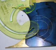
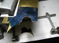
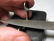
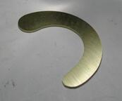
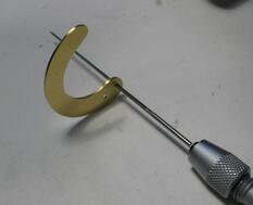
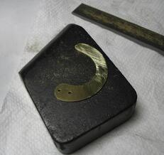
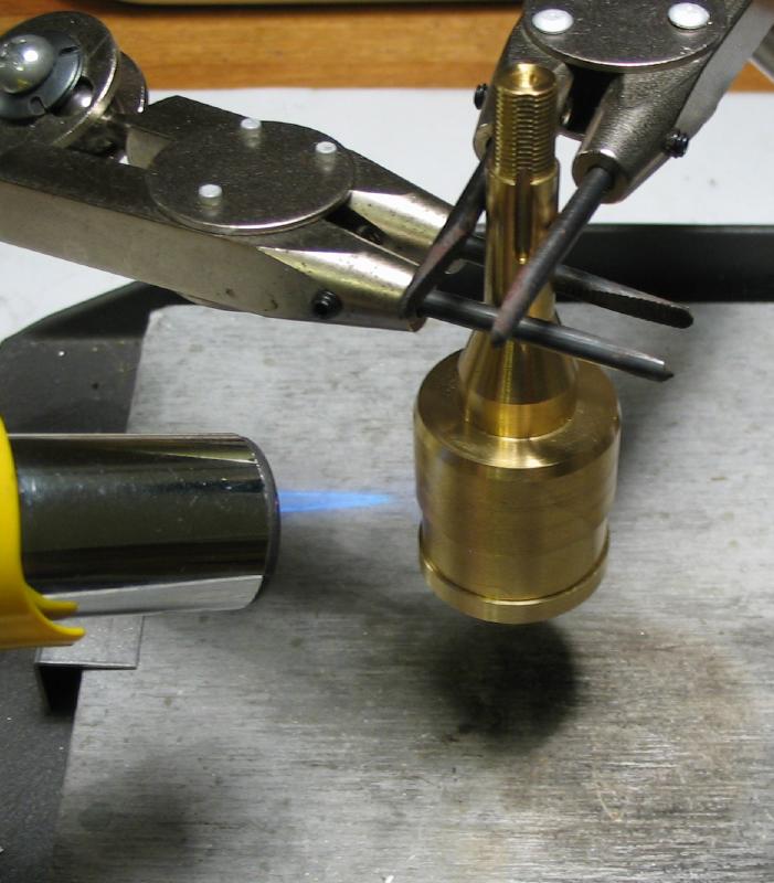
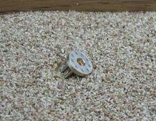
The click was laid out with radius gauge and french curve, and then sawed out and filed to the starting shape. It is prescribed to hammer harden the brass to give it a spring. The brass sheet I used has demonstrated itself as being fairly hard and difficult to work and was used as is.
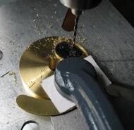
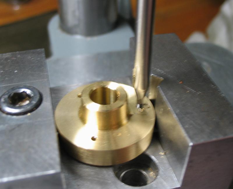
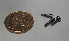
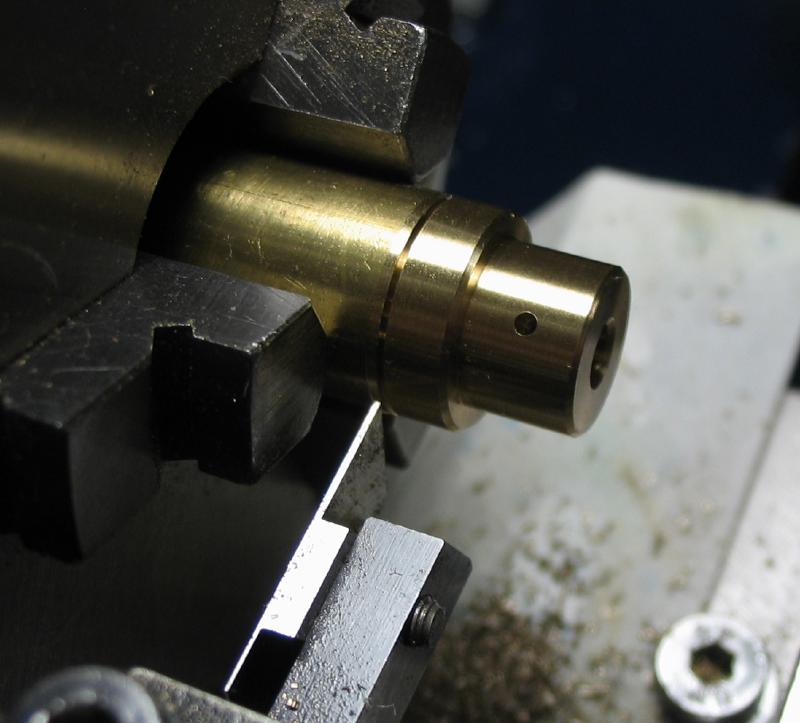
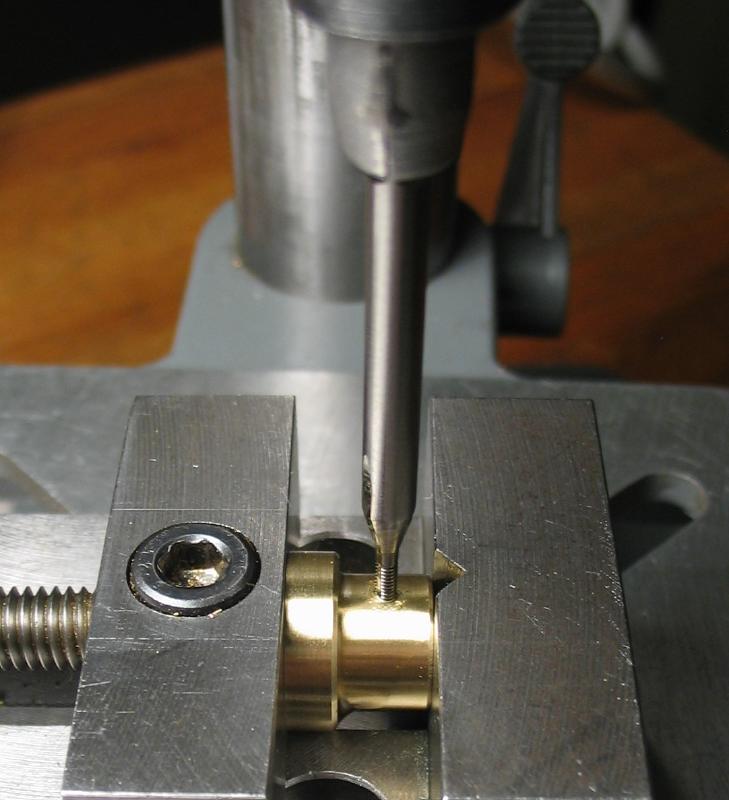
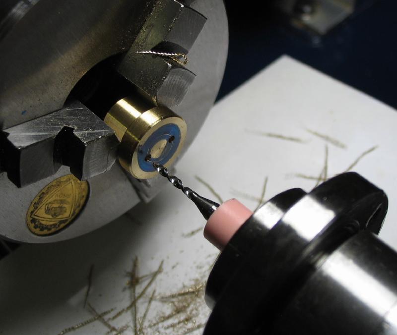
The positions for two screws were drilled with the parts clamped to the drill press, and the holes in the click opened with a broach to pass the screws and the holes in the pulley tapped #0-80. A pair of screws were made to fit as well.
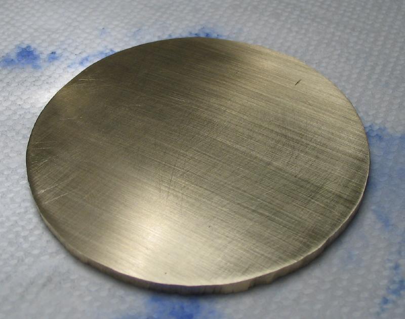
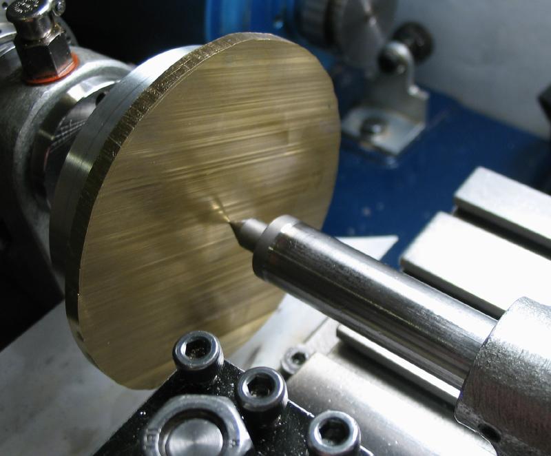
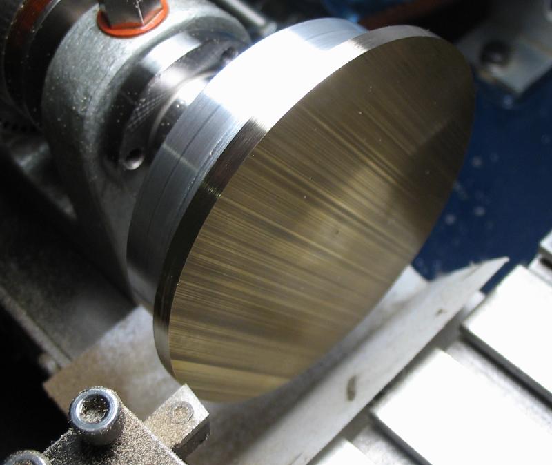
The wheel was started from 3" x 1/8" brass plate. A circle of about 70mm diameter was scribed from a center punch mark and sawed out. The back face was smoothed on emery paper and attached to my largest yet cement chuck with super glue. It is positioned and held in place with the tailstock center in the center mark.
.
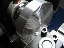
The cement chuck was made from an aluminum disc machined to fit a collet-style adapter that was made previously for a wood faceplate. The details on making the aluminum disc are on the cement chuck page. The chuck was freshly faced and grooves added with plunge cuts. Super glue was liberally applied and the wheel blank pressed into place with the tailstock center and held firmly for a few moments and then left to cure.
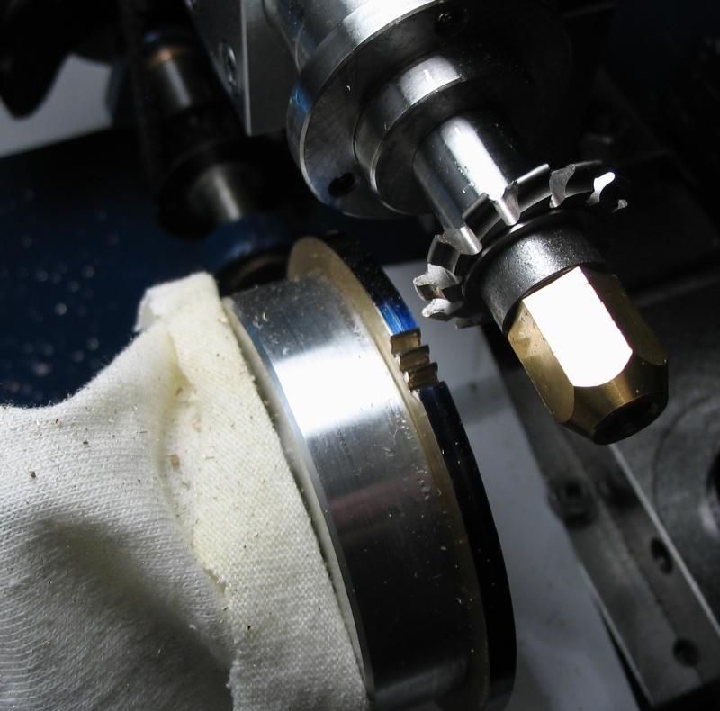
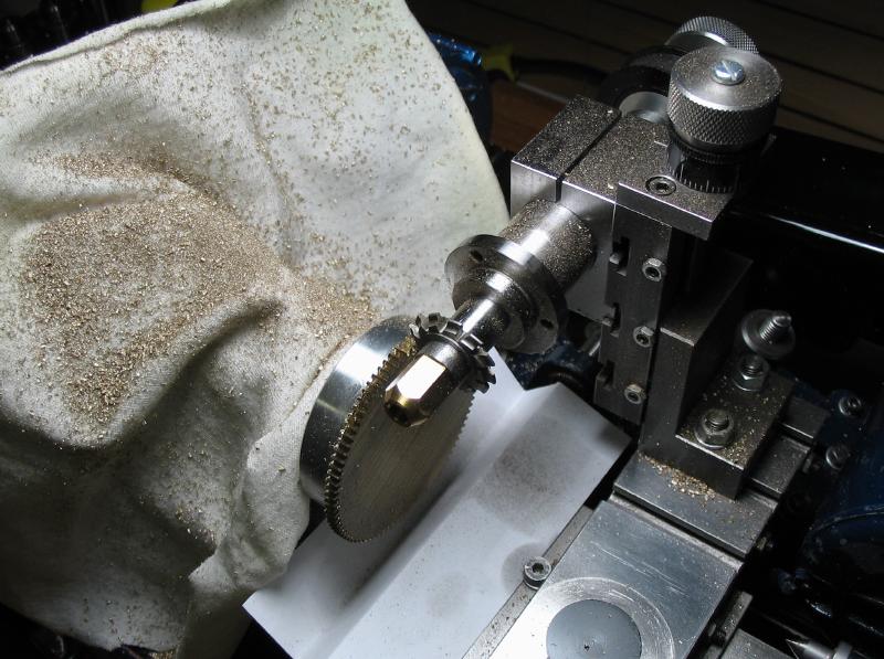
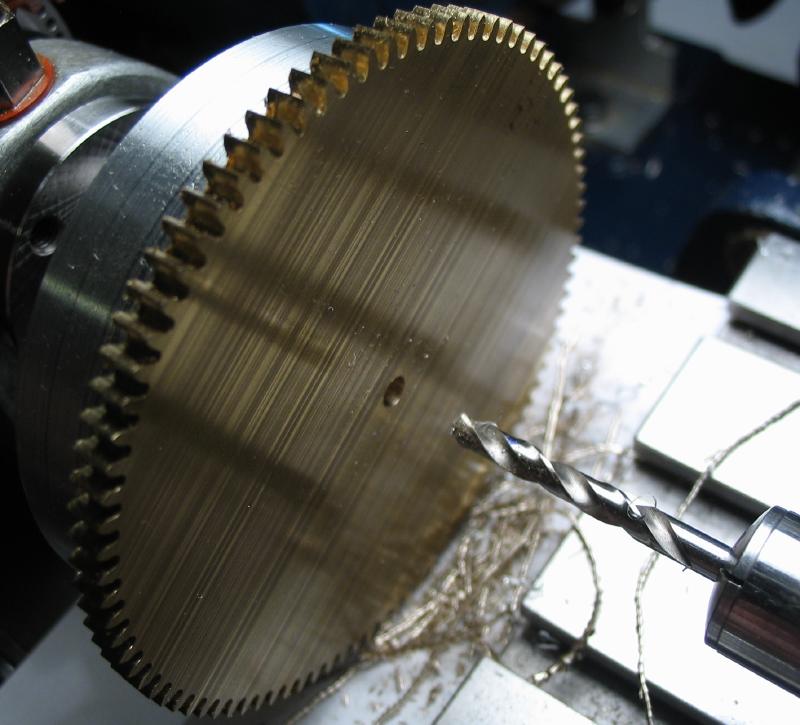
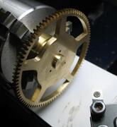
The brass blank was turned to the full diameter, in this case about 69.38mm. The usual procedures for cutting wheel teeth was employed. Centering the cutter was difficult since the milling spindle needed to be mounted fairly high to cut this relatively large wheel and was unable to lower enough to use the micrometer centering tool. The edge of the wheel was colored blue with a Sharpie, which helps to witness when the desired depth of cut is reached. The desired depth was found by lowering the cutter in steps approaching the calculated full depth (2.25mm) and successively cutting the first two adjacent spaces, which makes one completed tooth. The 90 count index plate provided the necessary divisions and the cutter was run at full speed and at full depth once found. Perhaps an overcompensation, but a cloth can be seen in the photo covering the headstock that helps keep brass chips from getting into tight spots and easier clean up.
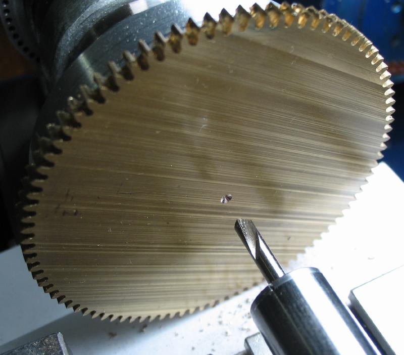
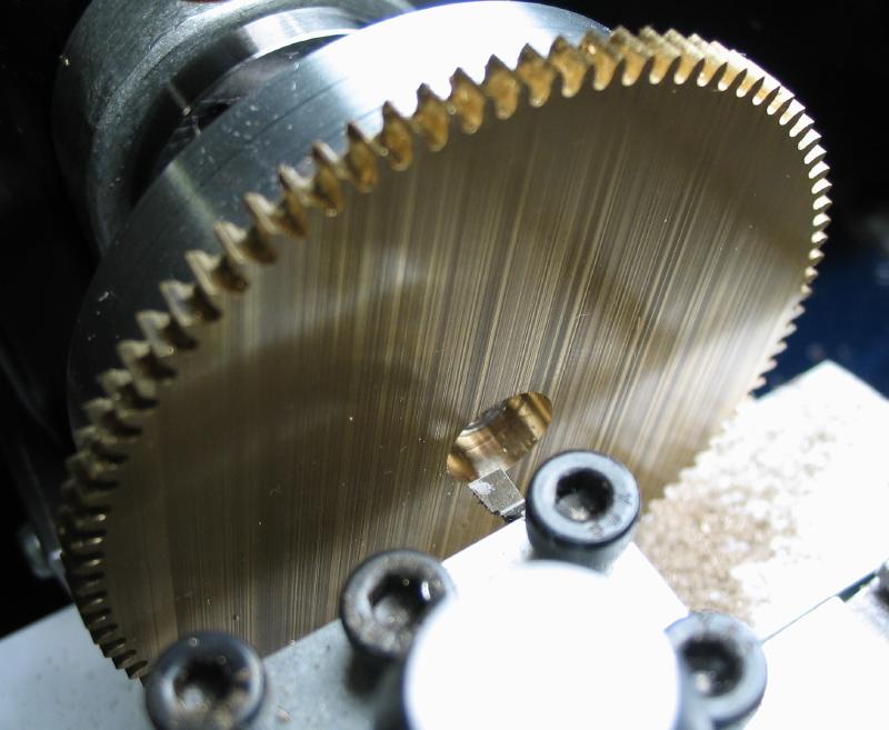
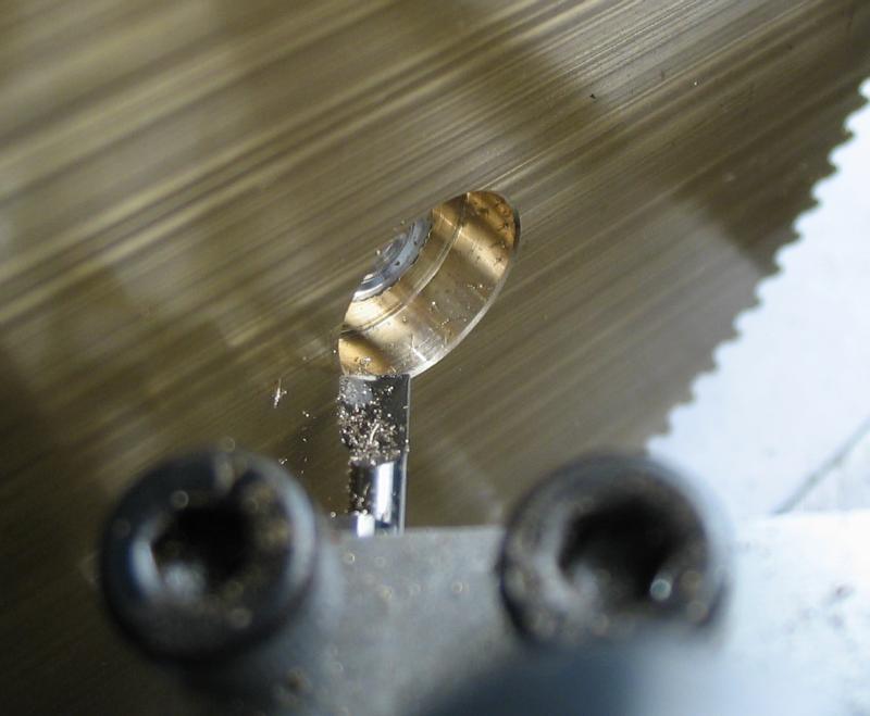
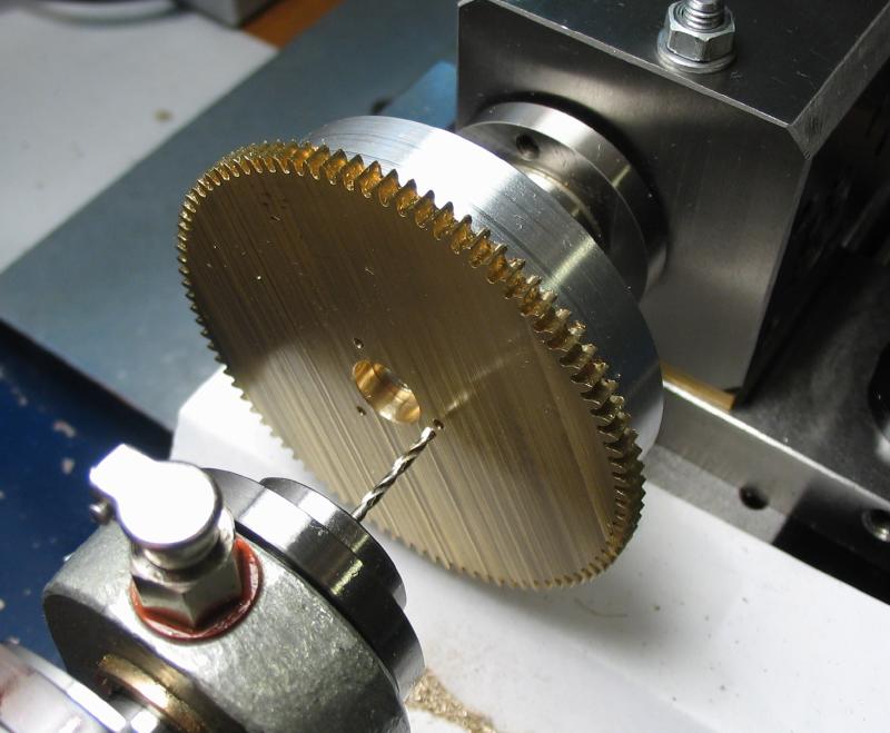
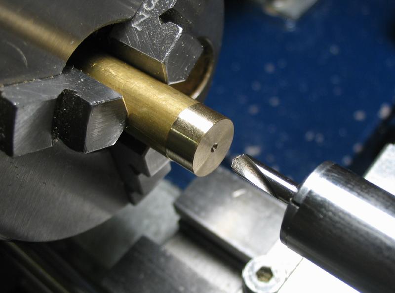
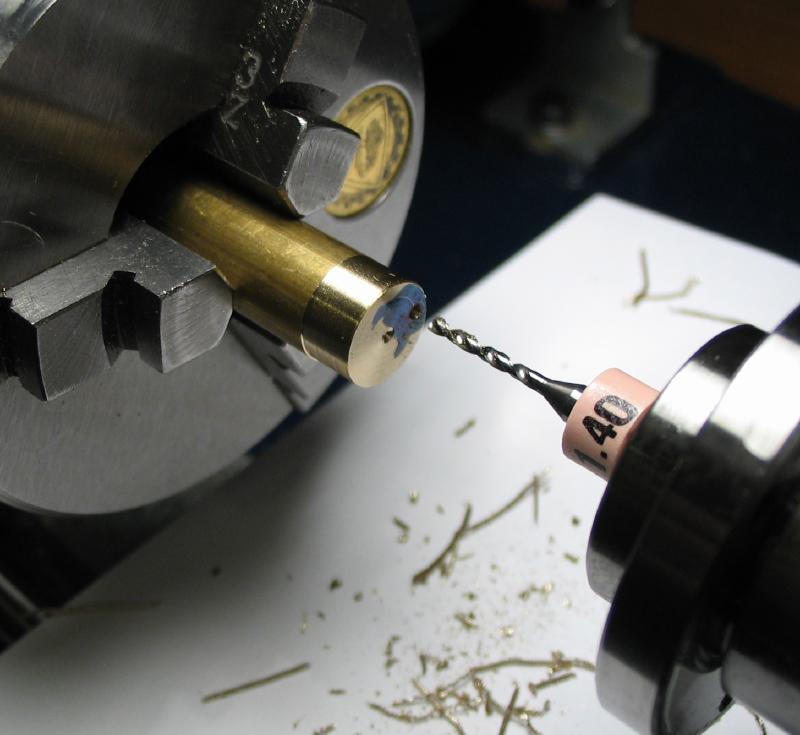
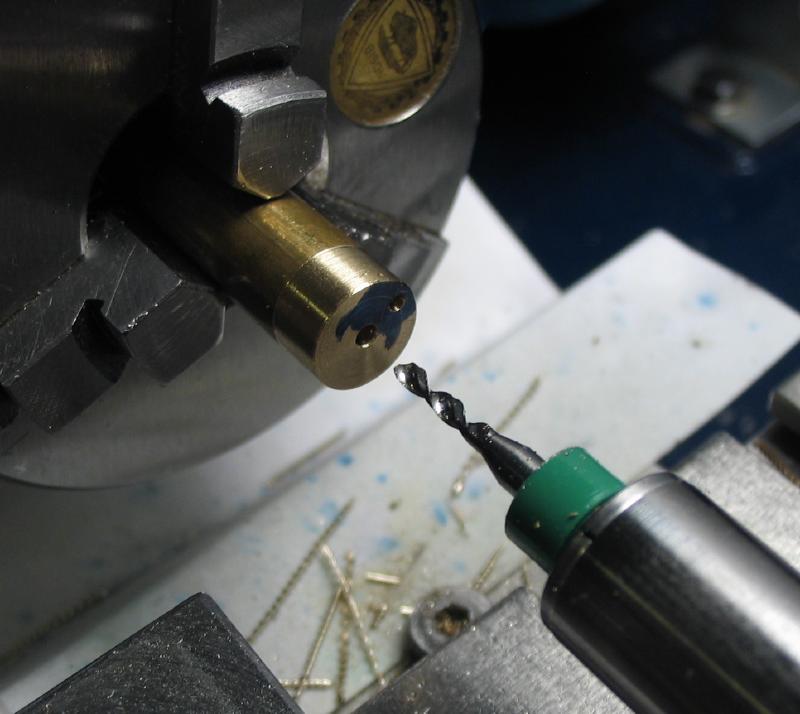
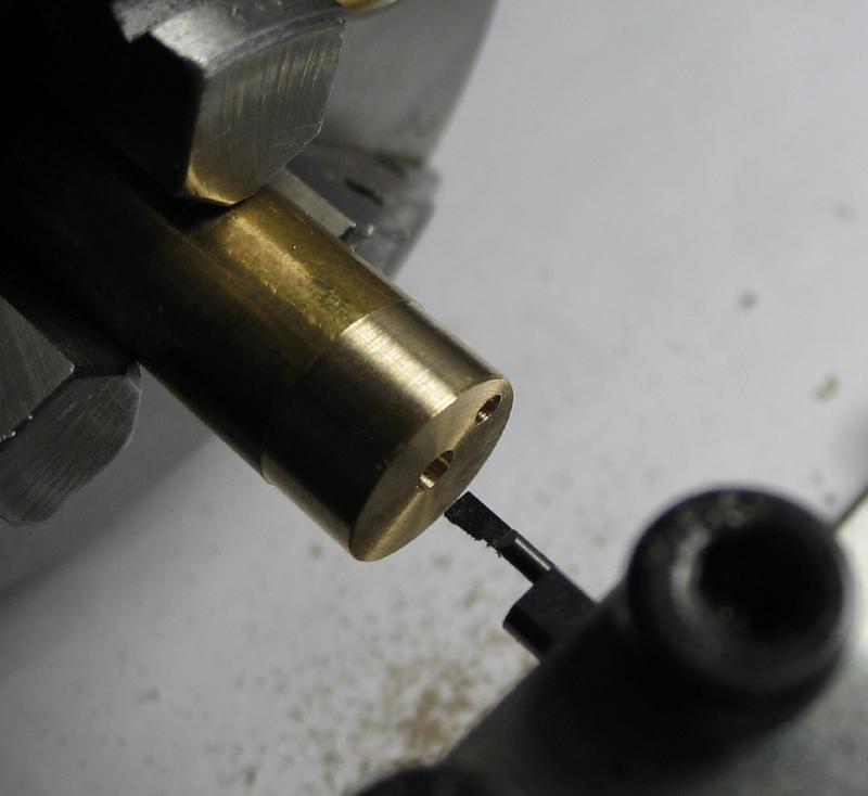
The center bore was formed while the wheel was still mounted by spot drilling, drilling and boring open to 10mm. In the last photo, the hole is countersunk with the boring bar and can be seen that the depth of the bore was barely through as to not needlessly turn away the cement chuck.
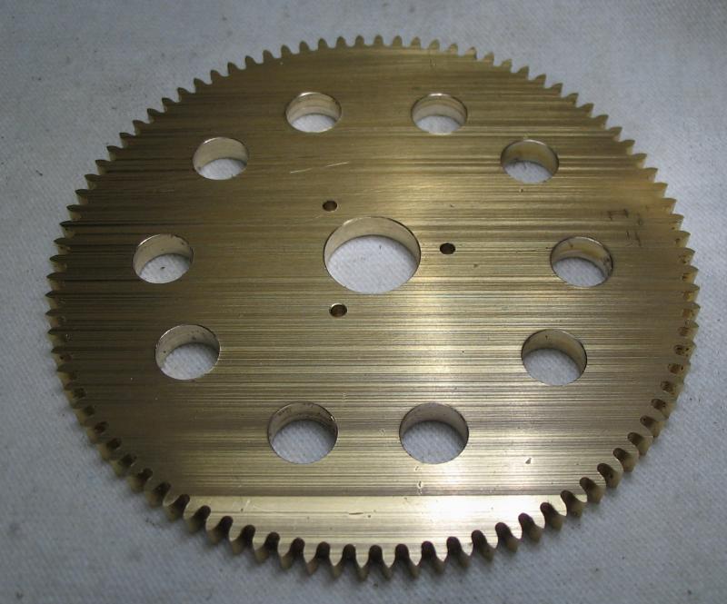
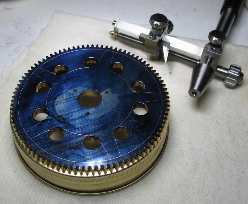
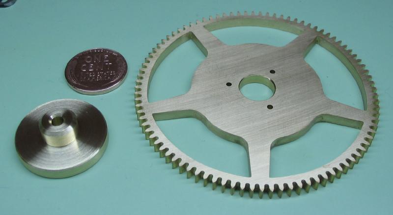
The chuck and wheel were moved to the dividing head to drill screw holes for attaching to the wheel collet and the starting holes for the spoke cut outs. The wheel described in Mr. Wild's book is a stock plastic wheel that is drilled with five holes to allow the pawl on the pulley to engage. Instead, I drilled similar size holes on the same radius, but then opened these up to a more usual spoke shape but with rounded corners next to the hub. The wheel was removed from the cement chuck by heating.
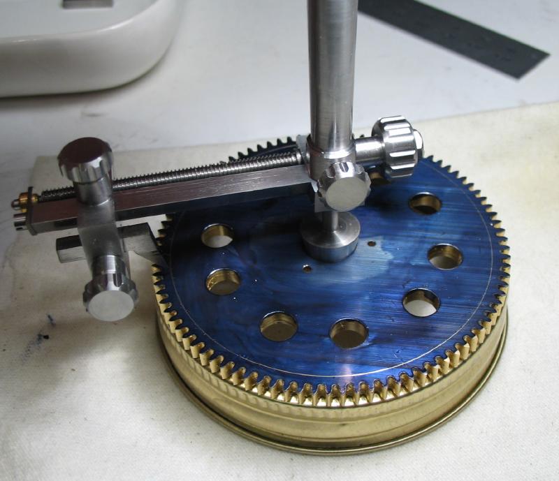
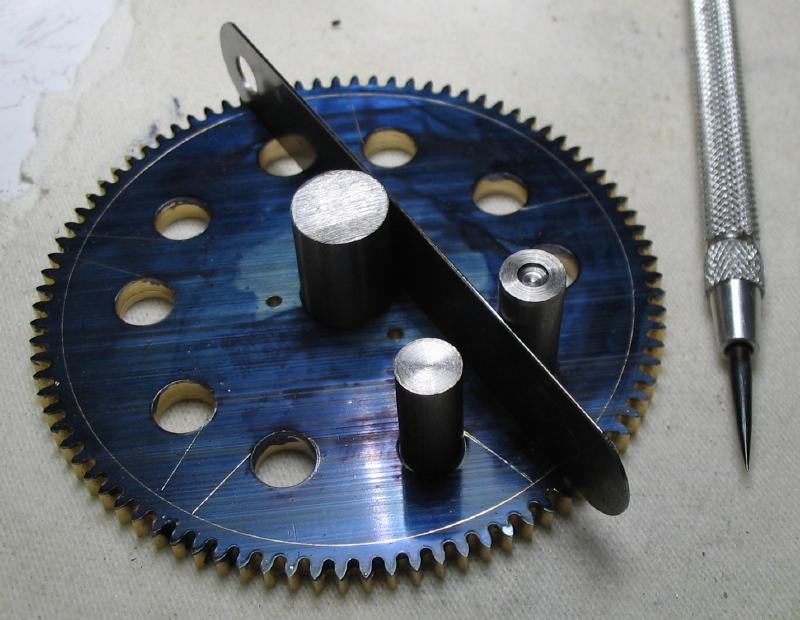
The rim and hub diameters were laid out with a compass and the spokes scribed using short piece of rod fitted into the holes and a feeler gauge used as a straight edge. The work is supported on a mason jar lid band, which is only mentioned since I was unsure when first looking at the photos...
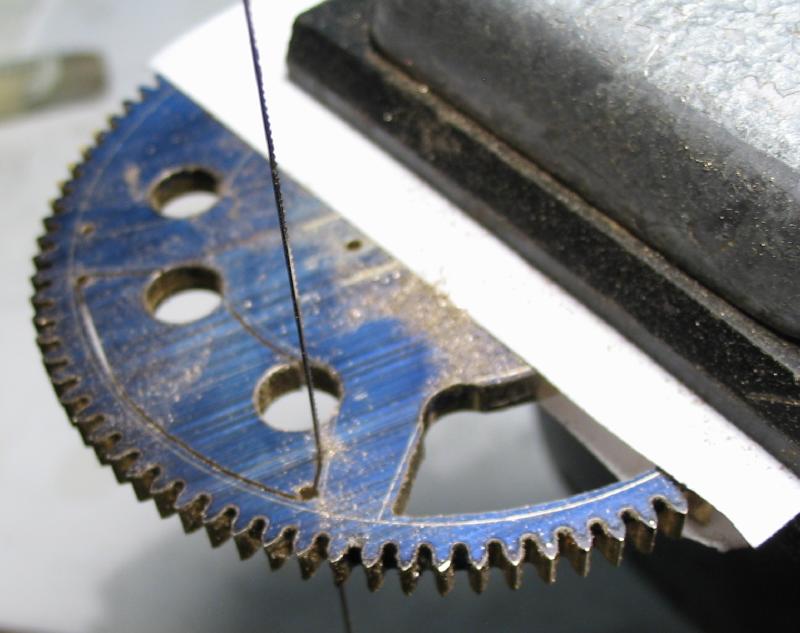
Additional holes were drilled near the remaining corners and a jewelers saw used to saw out each section.
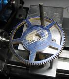
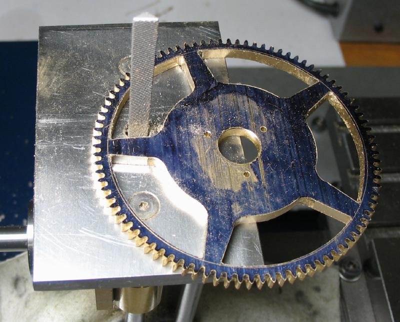
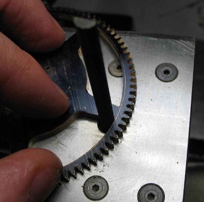
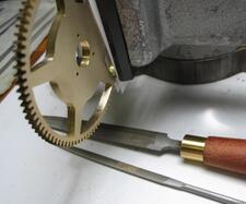
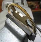
Since my sawing was not very close to the scribed lines, the filing machine was used to remove the bulk of the remaining material. The final shape was found with various files and finally with emery paper wrapped around a suitably shaped file. A set of aptly named crossing files had been recently acquired and used here for drawing-filing the inside rim. They are 4 inch Grobet files of 0, 2 and 4 coarseness and shown with needle-style files of the same shape and includes a fine 6 cut.
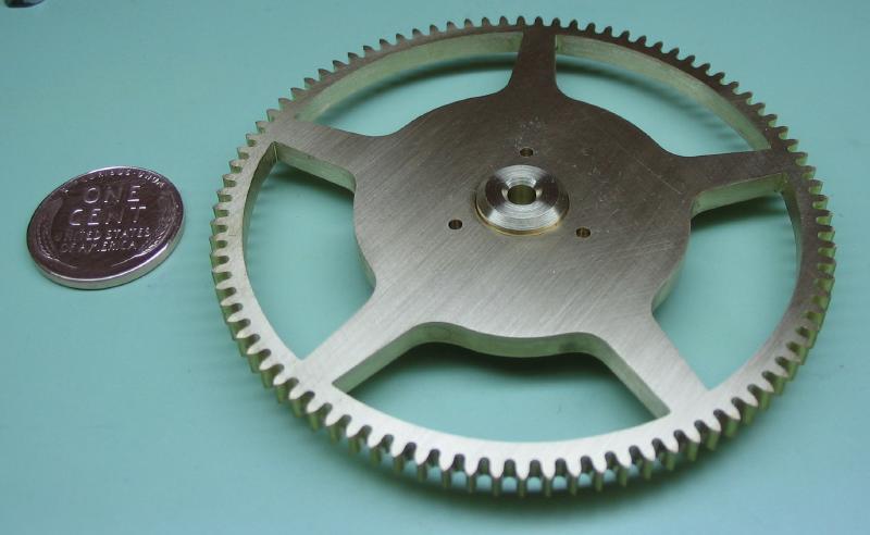
The wheel collet was started from a short length of 1 inch diameter brass rod. The rod was reduced to about 22mm diameter and then a spigot turned that is a snug fit to the center bore of the wheel and about 1.5mm greater in length. It was then drilled and reamed to 6mm and corners chamfered and countersunk. The positions for the screws were found using the wheel to double check and then drilled. The work was parted off, although the parting tool was not quite long enough so this was finished with a hack saw. The parted face was turned and the holes then tapped #0-80.
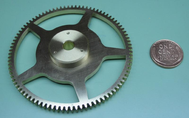
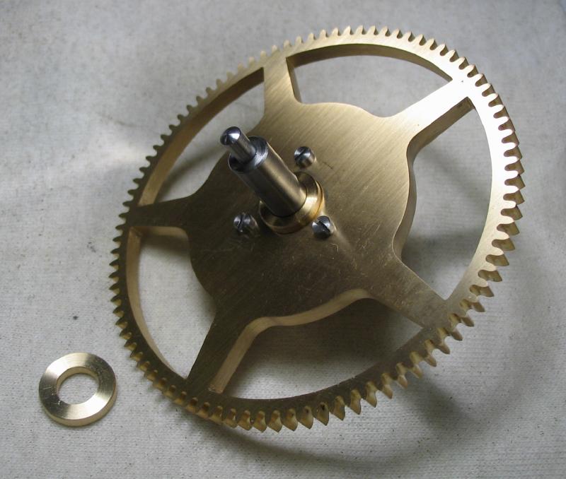
Three #0-80 screws were made in the usual manner and completed wheel is shown.
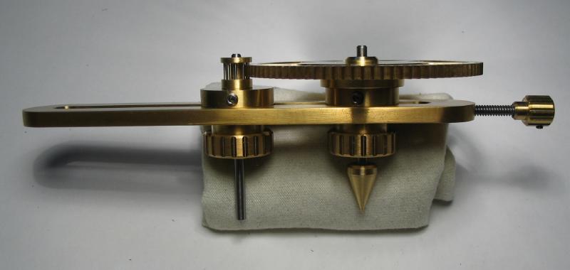
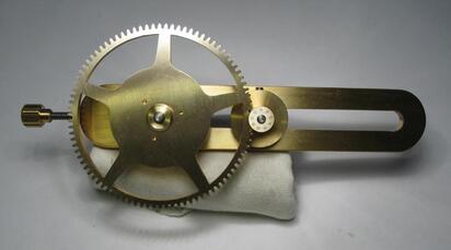
An adapter for holding the wheel on the depthing tool was made from the left over brass from making the collet and it is very similar in construction. It was left at about 1 inch diameter and is reamed to match the depthing tool runner rather than the final arbor, and it lacks screw holes so it will be freely moving. The adapter acts as a temporary collet of sorts to mount the wheel on the runner of the depthing tool and also raises the wheel to a height that mates with the pinion.
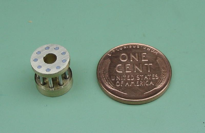
The mating pinion for the main wheel will be of the lantern pinion style. This style was chosen primarily due to pinion cutters being not available for 9 leaf pinions. I am following the method described in Bill Smith's video on wheel and pinion making. The bobbin is made from brass rod, which is turned true and a parting tool used to hog out the waist portion. It was drilled and reamed 3mm and then parted off. The parted bobbin was mounted onto a piece of 3mm drill rod with super glue; the bobbin was a very snug fit and the glue hardened fairly quickly so it is not completely driven on as can be seen in the photo. Also, it can be useful to turn a center point on the arbor to help centering the work and drill bit in the next steps, however, the centering and drill offset was accomplished here with the collet-mounted micrometer tool.
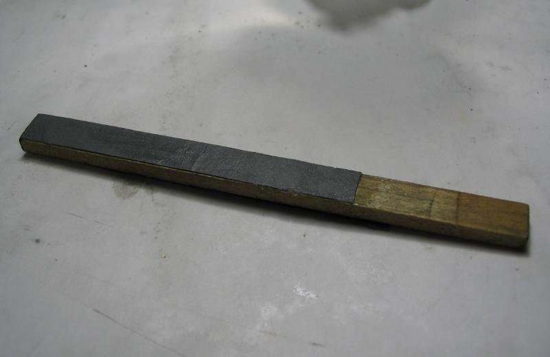
The arbor and bobbin were held in the dividing head and the 9 positions drilled using an under-sized clockmaker's drill (0.034") in the top flange only. A drill bit was made from a length of blued pivot steel (the same steel wire that will be used for the trundles). I did not photograph the drill making method since that took about 7 or 8 attempts to get a working example but still left something to be desired. I followed Mr. Smith's technique of holding in a pin vise and shaping by hand on an India bench stone to form two opposing flats and the cutting edges. Cutting oil was applied and the drill used to ream the top flange and drill into the bottom flange for about 1mm depth. Using a drill made from the same material should help obtain a snug and upright fit of the pins when installed. The wire for the pin is 0.037" (~0.94mm) in diameter and this was estimated from the formula tables provided for PP Thornton cutters. Although formulae for a 9 leaf pinion are not provided, the leaf thicknesses for ≤8 and ≥10 leaf pinions are 1.05M and 1.25M, respectively, and I went with the latter. So, for a Module of 0.75, the leaf thickness (i.e., trundle diameter) should be about 1.25(0.75) = 0.9375 mm.
The trundles for the pinion were made from blue pivot steel, which was polished with 600 grit emery paper and crocus cloth. The wire was test fit into a hole and an excess length marked with a file. The wire is quite hard and was parted by either notching with a file and snapping off with pliers or using a small grinding disc in the Foredom tool to cut through. The holes in the bobbin were countersunk with a ball end bur to clean up corners and washed to remove any debris prior to installing the pins.
The pins were installed with a drop of Loctite 609 in the top and bottom holes. The Loctite cures in the absence of air and in contact with metal. After allowing to set for about 10 minutes, the excess adhesive was removed with a brush and naptha since any residual adhesive on the working area of the trundles could cause issues and it will of course be more difficult to remove once hardened. The Loctite is green in color, which helps to see residue.
The excess length of the trundles was removed by grinding with a small mounted stone held in the Foredom tool to even the pins out, and they were then ground smooth on the coarse side of the India bench stone and finally smoothed on emery paper. The work was washed thoroughly again and can be seen drying in wood chips.
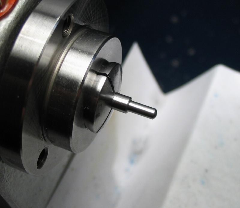
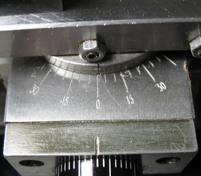
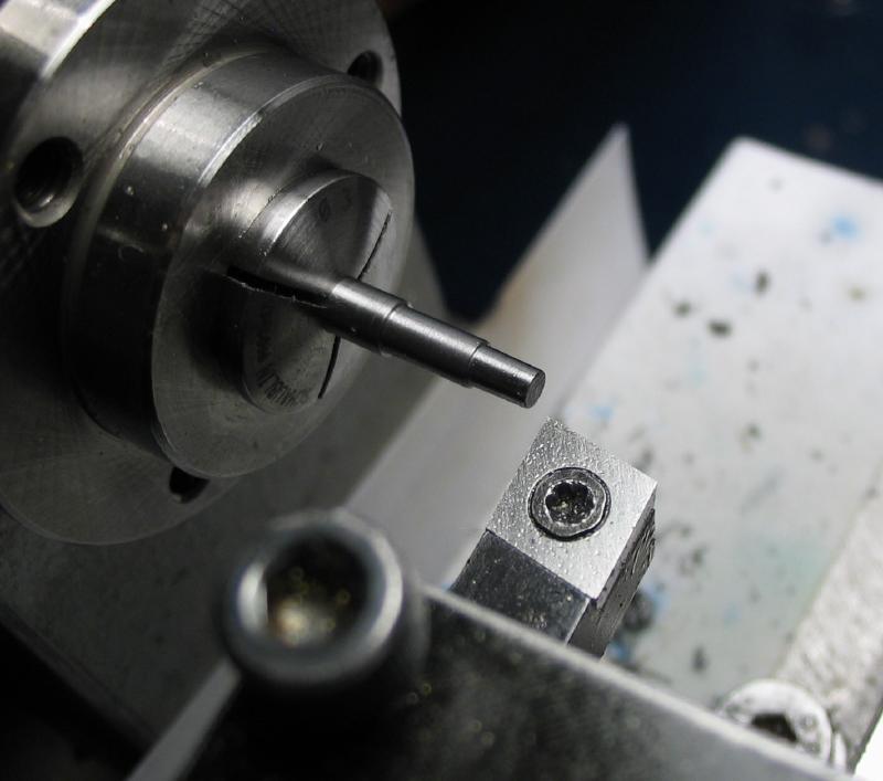
The arbor for the lantern pinion and suspended escape pinion was made from 3mm drill rod. One end turned for the pivot and the other receiving a pivot and boss to hold the suspend pinion. This boss was turned with a slight taper (about 1 degree).
The pinion was turned and the offset pin location drilled. The center hole was drilled and then counterbored with a similar 1 degree taper to provide a tight fit with the arbor.
The work was then parted off, and the reverse face cleaned up. The pin was turned from 1/16" drill rod and to fit the off set hole.
In the photo, the lantern pinion is obviously not yet installed and the suspended pinion is shown on the arbor but is not pressed fully into place.
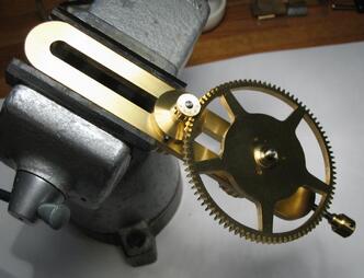
The wheel and pinion can mounted on the depthing tool for determining the optimum center distance. The pinion runner was turned to 3mm to fit the lantern pinion and the wheel is mounted on the adapter described above. A couple photos of the assembly are shown and I found mounting in the vise allows for a bit more control while testing.
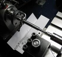
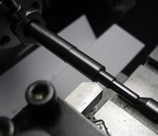
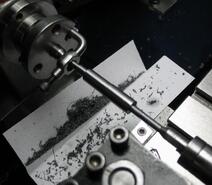
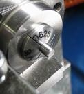
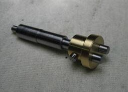
The arbor for drive pulley and main wheel was made from 1/4" drill rod. An over-sized length was center drilled on both ends and then mounted between centers to turn the seat for the wheel collet, the pivot, and boss that the suspended pinion will mount onto.
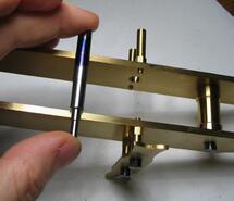
The between-plate length was measured and also marked by direct comparison and returned to the lathe to turn the pivot on the reverse end and bring to final length. Not shown, but once turning is complete, the centers can be sawed off and the ends rounded over.
The suspended 2-pin lantern pinion was made from brass rod. The rod was turned to the desired shape, drilled and reamed to fit the arbor. Corners were relieved by turning and use of a countersink, and the position for a set screw drilled. After parting off the work, the set screw position was tapped. The work was reversed in the lathe chuck and the location for the two pins laid out, drilled and reamed.
The pins were turned from 1/8" drill rod and a set screw was made with #0-80 threads, although the process was not photographed.
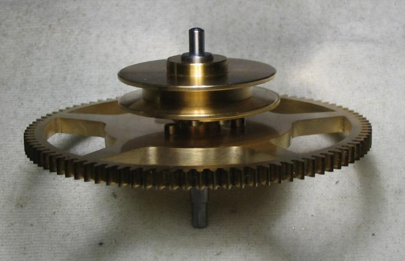
The wheel collet was given a boss that provides clearance for the screws, but I neglected to account for the screws in the pulley as well, so a washer was made to separate the wheel and pulley by another 1/16".
Photos of the washer, the washer installed, and resulting separation of the wheel and pulley on the arbor.

